

KitchenAid KICU509X, JUC4430X, JIC4536X, KICU569X Tech Sheet
FOR SERVICE TECHNICIAN'S USE ONLY
Tech Sheet Do not discard
ADANGER
Electrical Shock Hazard
Only authorized technicians should perform diagnostic
voltage measurements.
After performing voltage measurements, disconnect
power before servicing.
Failure to follow these instructions can result in death
or electrical shock.
Disconnect power before servicing.
Replace all parts and panels before operating.
Failure to do so can result in death or electrical shock.
AWARNING
Electrical Shock Hazard
Voltage Measurement Safety Information
When performing live voltage measurements, you must do the following:
• Verify the controls are in the off position so that the appliance does not start when energized.
• Allow enough space to perform the voltage measurements without obstructions.
• Keep other people a safe distance away from the appliance to prevent potential injury.
• Always use the proper testing equipment.
• After voltage measurements, always disconnect power before servicing.
Acronyms
• PC: Power Control Board
• NTC: Negative Temperature Coefficient
and
Manual Configuration Mode
To Enter Manual Configuration Mode:
NOTE: This menu is accessible only during the first minutes after the
cooktop is plugged in.
1. Remove the key-lock functionality by pressing the Control Lock
button.
2. Press the following keys sequentially (a beep will sound after each key
press): Timer "-", Timer "+", Timer"-", Timer "+", Control Lock.
After the keystroke combination is pressed, a "CO" will appear on the
display.
3. Press the Control Lock button.
An "00" will appear on the display.
Abbrevialons
• Ul: User Interface board
4. Configure the correct cooktop model number by choosing one of the
following numbers.
Configuration Number Cooktop
23 KICU509X
24 JIC4430X
25 JIC4536X
26 KICU569X
Use the Timer buttons to see different numbers on the display, moving
sequentially and beginning at "00." The Timer "+" button will increase
the number by 1, and the Timer"-" button will decrease the number
by 1.
5. Press the Control Lock button to confirm the configuration. The
configuration will then be downloaded into the cooktop.
This process will last a few seconds. The number of the cooktop
chosen will blink on the display. The cooktop will restart with the new
configuration written.
6. The cooktop is ready to use.
501961902035
FOR SERVICE TECHNICIAN'S USE ONLY
FOR SERVICE TECHNICIAN'S USE ONLY
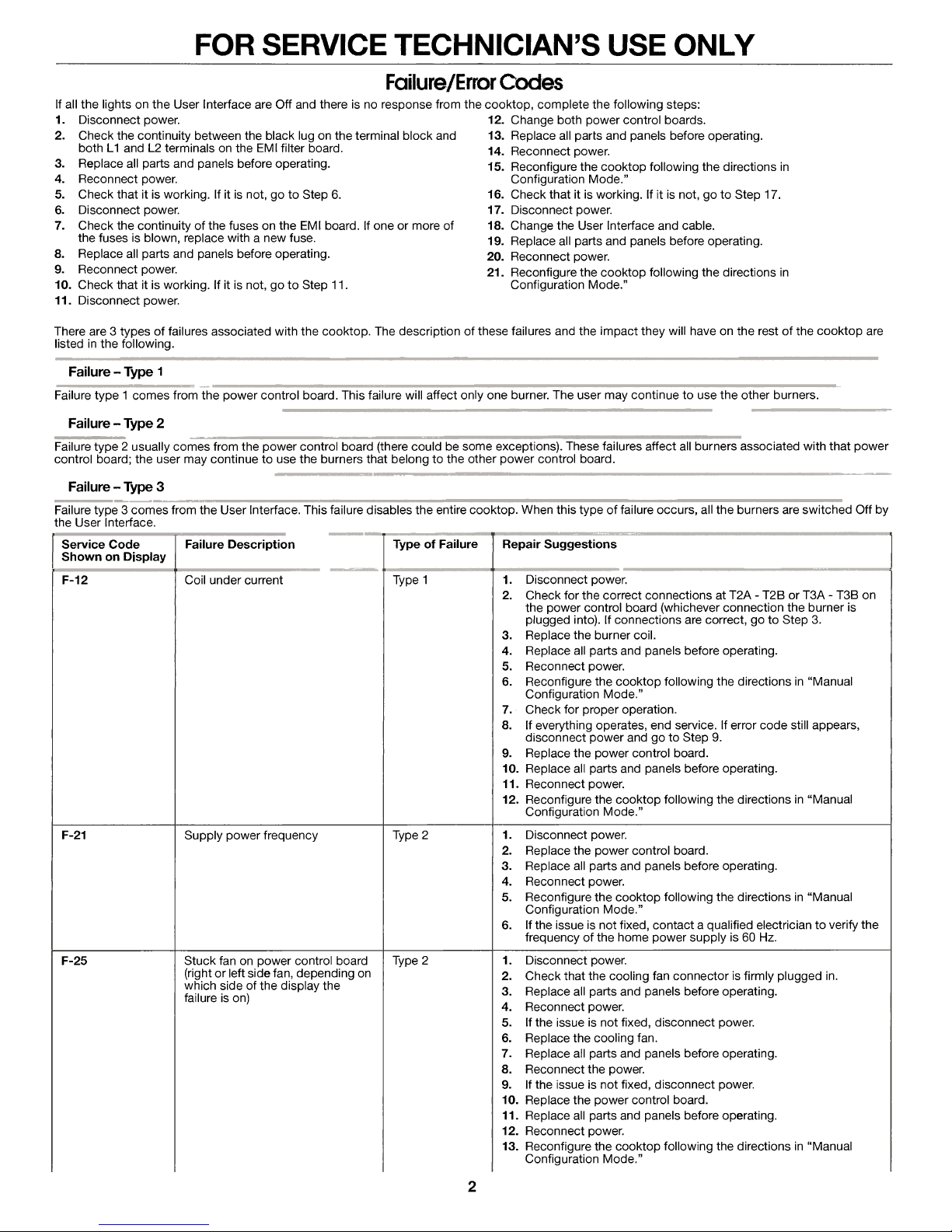
Failure/Error Codes
If all the lights on the User Interface are Off and there is no response from the cooktop, complete the following steps:
Disconnect power. 12.
1.
2.
Check the continuity between the black lug on the terminal block and 13. Replace all parts and panels before operating.
both L1 and L2 terminals on the EMI filter board.
3. Replace all parts and panels before operating.
4. Reconnect power. Configuration Mode."
Check that it is working. If it is not, go to Step 6.
5.
6. Disconnect power. 17. Disconnect power.
7. Check the continuity of the fuses on the EMI board. If one or more of 18. Change the User Interface and cable.
the fuses is blown, replace with a new fuse.
8. Replace all parts and panels before operating.
Reconnect power.
9.
10. Check that it is working. If it is not, go to Step 11.
11. Disconnect power.
There are 3 types of failures associated with the cooktop. The description of these failures and the impact they will have on the rest of the cooktop are
listed in the following.
Failure - Type 1
Failure type 1 comes from the power control board. This failure will affect only one burner. The user may continue to use the other burners.
Failure - Type 2
Failure type 2 usually comes from the power control board (there could be some exceptions). These failures affect all burners associated with that power
control board; the user may continue to use the burners that belong to the other power control board.
Failure - Type 3
Failure type 3 comes from the User Interface. This failure disables the entire cooktop. When this type of failure occurs, all the burners are switched Off by
the User Interface.
Service Code
Shown on Display
F-12
F-21 Supply power frequency
F-25 Stuck fan on power control board
Failure Description
Coil under current
(right or left side fan, depending on
which side of the display the
failure is on)
Type of Failure
Type 1
Type 2
Type 2
Change both power control boards.
14. Reconnect power.
15. Reconfigure the cooktop following the directions in
16. Check that it is working. If it is not, go to Step 17.
19. Replace all parts and panels before operating.
Reconnect power.
20.
21.
Reconfigure the cooktop following the directions in
Configuration Mode."
Repair Suggestions
1. Disconnect power.
2. Check for the correct connections at T2A - T2B or T3A - T3B on
the power control board (whichever connection the burner is
plugged into). If connections are correct, go to Step 3.
3. Replace the burner coil.
4. Replace all parts and panels before operating.
5. Reconnect power.
6. Reconfigure the cooktop following the directions in "Manual
Configuration Mode."
7. Check for proper operation.
8. If everything operates, end service. If error code still appears,
disconnect power and go to Step 9.
9. Replace the power control board.
10. Replace all parts and panels before operating.
11. Reconnect power.
12. Reconfigure the cooktop following the directions in "Manual
Configuration Mode."
1. Disconnect power.
2. Replace the power control board.
3. Replace all parts and panels before operating.
4. Reconnect power.
5. Reconfigure the cooktop following the directions in "Manual
Configuration Mode."
6. If the issue is not fixed, contact a qualified electrician to verify the
frequency of the home power supply is 60 Hz.
1. Disconnect power.
2. Check that the cooling fan connector is firmly plugged in.
3. Replace all parts and panels before operating.
4. Reconnect power.
5. If the issue is not fixed, disconnect power.
6. Replace the cooling fan.
7. Replace all parts and panels before operating.
8. Reconnect the power.
9. If the issue is not fixed, disconnect power.
10. Replace the power control board.
11. Replace all parts and panels before operating.
12. Reconnect power.
13. Reconfigure the cooktop following the directions in "Manual
Configuration Mode."
2
 Loading...