

Page 1
A Note to You
Thank you for buying a
KitchenAid®appliance.
KitchenAid designs the best tools for the
most important room in your house.To
ensure that you enjoy years of troublefree operation, we developed this Use
and Care Guide. It contains valuable
information about how to install, operate
and maintain your hot water dispenser
properly and safely. Please read it
carefully.
Also, please complete and mail the
Product Registration Card provided
with your hot water dispenser. This card
helps us notify you about any new
information for your hot water dispenser.
Part No.3193348
®
Record your model’s information
Write down the following information about your hot water dispenser to better
help you obtain assistance or service if you ever need it. You will need to know
your complete model number and serial number.You can find this information
on the model and serial number label/plate.
If you need assistance or service, first see the “Troubleshooting”section of this
book. After checking “Troubleshooting,” additional help can be found by
checking the “Requesting Assistance or Service” section.
Builder/dealer name
Address
Phone number
Model number
Serial number
Purchase date
Date installed
(See the “Par ts and Features” section for model and serial number label/plate
location.)
Keep this book and your sales slip together for future reference.
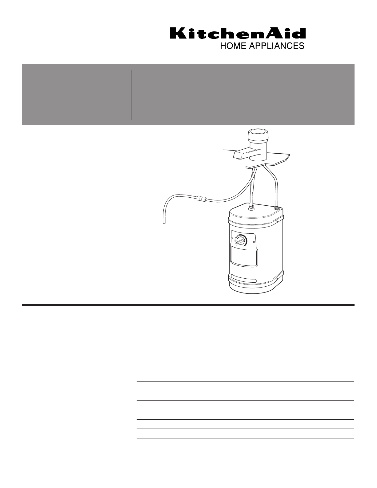
Installation Instructions
and
Use and Care Guide
IMPORTANT:
Read and save these instructions.
IMPORTANT:
Installer: Leave this guide with
homeowner.
Homeowner: Keep this guide for
future reference.Save this guide for
local electrical inspector’s use.
Instant Hot
®
Hot Water
Dispenser
Page 2
Table of Contents
2
A Note to you . . . . . . . . . . . . Cover
Hot Water Dispenser Safety . . . . 2
Parts and Features . . . . . . . . . . . 3
How your hot water
dispenser works . . . . . . . . . . . . . . 3
Before You Start . . . . . . . . . . . . . 4
Tools and materials needed. . . . . . 5
Parts supplied. . . . . . . . . . . . . . . . 5
Electrical requirements . . . . . . . . . 5
Water supply requirements . . . . . . 5
Installation Instructions . . . . . . . . . 6
Using Your Hot Water
Dispenser . . . . . . . . . . . . . . . . . 10
Before using the first time . . . . . . 10
Temperature control . . . . . . . . . . 10
Dispensing hot water . . . . . . . . . 10
Hot water dispenser uses . . . . . . 10
Caring For Your Hot
Water Dispenser . . . . . . . . . . . . 11
Energy-saving tips and . . . . . . . . .
preparation for periods
of nonuse . . . . . . . . . . . . . . . . . . 11
Cleaning the spout screen. . . . . . 11
Troubleshooting. . . . . . . . . . . . . 12
Requesting Assistance
or Service . . . . . . . . . . . . . . . . . 13
Warranty . . . . . . . . . . . . . . . . . . 15
Hot Water Dispenser Safety
WARNING:To reduce the risk of
fire, electrical shock, or injury
when using your hot water
dispenser, follow these basic
precautions:
• Plug into grounded 3 prong
outlet.
• Do not remove ground prong.
• Do not use an adapter.
• Do not use an extension cord.
• Disconnect power before
servicing.
IMPORTANT SAFETY
INSTRUCTIONS
You can be killed or seriously
injured if you don’t follow
instructions.
D ANGER
Your safety and the safety of others are very important.
We have provided many important safety messages in this manual and on
your appliance.Always read and obey all safety messages.
All safety messages will tell you what the potential hazard is, tell you how
to reduce the chance of injury, and tell you what can happen if the
instructions are not followed.
You can be killed or seriously
injured if you don’t immediatel
y
follow instructions.
WARNING
This is the safety alert symbol.
This symbol alerts you to potential hazards that can kill or hurt you
and others.
All safety messages will follow the safety alert symbol and either the word
“DANGER” or “WARNING”.These words mean:
Page 3
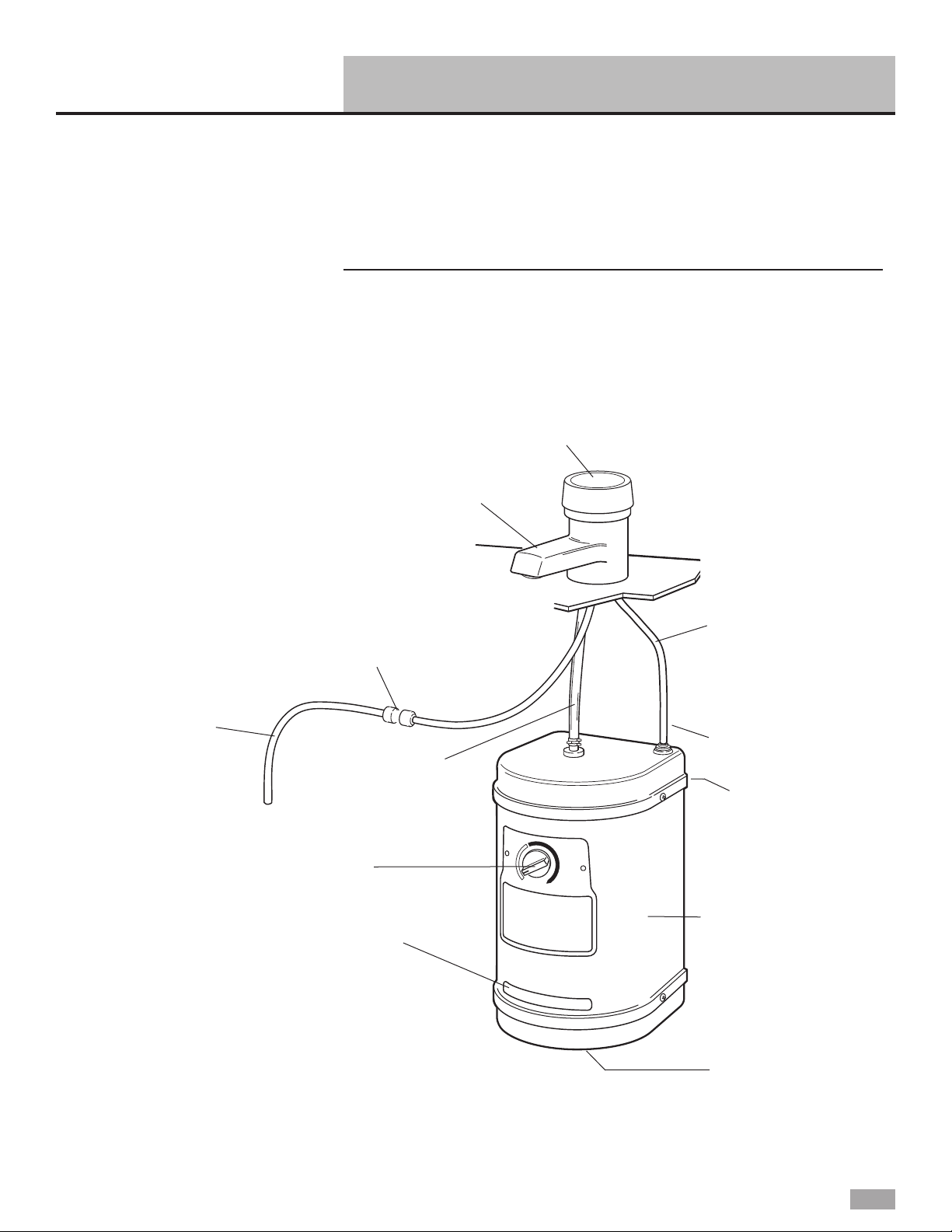
Parts and Features
3
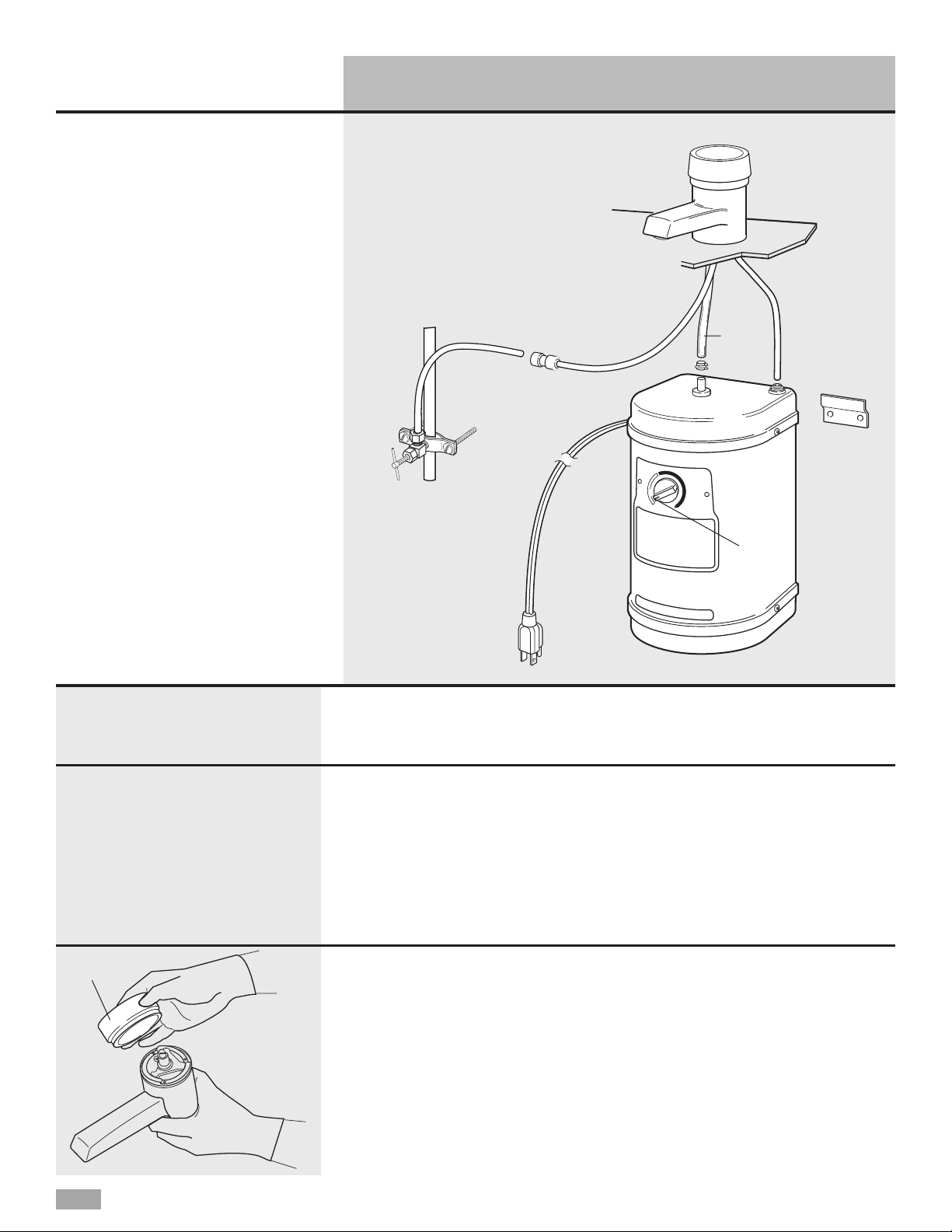
Use this hot water dispenser
illustration to help you quickly learn
how to install and use your new hot
water dispenser. Page numbers are
listed to help you find more detailed
information about that feature.
Flexible
tubing
(Page 8)
Spout
(Pages 6, 7, 11)
On/Off cap
(Pages 6, 7, 9, 10)
Cold water
supply line
from saddle
valve
(Page 9)
Temperature
Control
(Pages 9, 10)
Cold water supply
line from spout
(Page 8)
Tank
(Page 7)
Quick-connect fitting
(Page 8)
Water is electrically heated to a
brewing/cooking hot 190°F (88°C)
by a tank that mounts under the
sink. A ther mostat maintains it at
this approximate temperature.When
you turn the On/Off Cap, cold water
enters the bottom of the tank and
forces hot water out of the faucet.
The system is vented so the tank is
not pressurized.
How your hot water dispenser works
Quick-connect fitting
(Page 9)
Model and
serial number
label/plate
Drain plug
(Page 11)
Mounting bracket
located behind tank
(Page 7)
Page 4
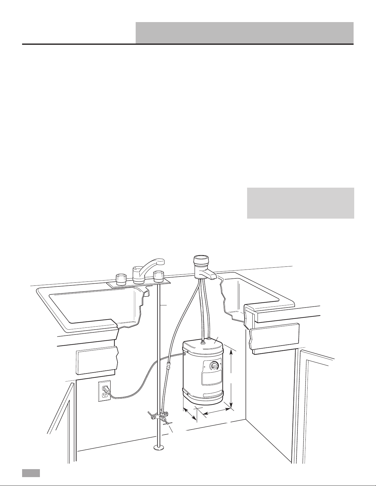
Before You Start
4
42" (106.7 cm) max. —
electrical outlet to hot
water dispenser tank.
Tank
must be
mounted
vertically.
Spout installed in spray hose
opening in sink.
If spout is not to be
installed in sink spray hose
opening, cut 1-1/16"
(2.7 cm) min. — 1-3/8"
(3.5 cm) max. dia. sink or
countertop cutout
Saddle
valve
1-1/8" (2.9 cm) max.
countertop or sink thickness
Important: Observe all governing
codes and ordinances.
Cold
water
line
Check location where hot water
dispenser will be installed. Proper
installation is your responsibility.
Make sure you have everything
necessary for correct installation. It is
the responsibility of the installer to
comply with installation specifications
and with state and local plumbing
codes.
Spout requires a 1-1/16" (2.7 cm) to
1-3/8" (3.5 cm) diameter opening in
sink or countertop. Spout can be
installed in place of sink spray hose.
For other installations, contact a
qualified installer for best procedure
to drill a hole through your type of
sink or countertop.Thickness of sink
or countertop hole must not exceed
1-1/8" (2.9 cm).
Cold water supply connection must
be available. (See “Water supply
requirements,” Page 5.)
Grounded electrical outlet is
required. (See “Electrical
requirements,” Page 5.) The outlet
should be located within 42"
(106.7 cm) of hot water dispenser
tank.
If spout is not to be installed in sink
spray hose opening, contact a
qualified installer for the best
procedure for cutting a spout
opening in your type of sink or
countertop.
Plumbing connections must comply
with all sanitary and plumbing
codes.
Do Not store or operate hot water
dispenser below 32°F (0°C).
Do Not use pipe sealing compounds.
They may get inside dispenser and
cause an unpleasant taste or smell.
Water connections use quickconnect fittings which Do Not
require sealing compounds to keep
them from leaking.
Temperature Control must be turned
to “Off” position and the dispenser
tank filled before connecting to
electrical supply.
This hot water dispenser is Not a
water purifier.Some installations
may require a water filtering system
to improve the quality of water.
6-3/4"
(17.1 cm)
5-5/8"
(14.3 cm)
11-1/8"
(28.3 cm)
Page 5

Before You Start cont.
ruler or
measuring tape
pliers
flat-blade
screwdriver
Tools and materials needed
Parts supplied
open-end wrench(es)
to fit saddle valve
gloves
5
hand or
electric drill
bucket or pan
tubing cutter
2 mounting bracket screws (and
2 plastic anchors if attaching to
dry wall)
1/4" (6.4 mm) O.D.
copper tubing
pencil
tank
mounting
bracket
gasket
tank
clamp
Remove parts from packages.
Check that all parts were
included.
spout
assembly
1/4" (6.4 mm)
drill bit
Saddle valve kit to fit
water supply line
Kit must meet all local
codes and ordinances.
safety
glasses
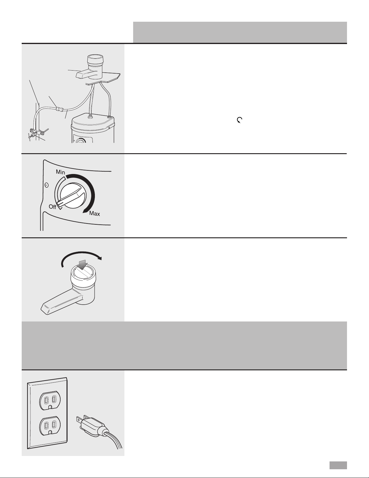
For your personal safety, the hot
water dispenser must be grounded.
This appliance is equipped with a
power supply cord having a 3-prong
ground plug. To minimize possible
shock hazard, the cord must be
plugged into mating, 3-prong, groundtype outlet, grounded in accordance
with all national and local codes and
ordinances. If a mating outlet is not
available, it is the personal
responsibility and obligation of the
customer to have a properly
grounded, 3-prong outlet installed by
a qualified electrician.
Recommended ground method
Electrical requirements
Electrical Shock Hazard
Plug into a grounded 3 prong
outlet.
Do not remove ground prong.
Do not use an adapter.
Do not use an extension cord.
Failure to follow these
instructions can result in death,
fire, or electrical shock.
WARNING
If codes permit and a separate
ground wire is used, it is
recommended that a qualified
electrician determine that the
ground path is adequate.
A 120-volt, 60-Hz, AC-only 15- or
20- ampere fused, grounded
electrical supply is required. It is
recommended that a separate circuit
serving only your hot water dispenser
be provided. Use an outlet that
cannot be turned on/off by a switch.
Water supply requirements
If local codes permit, the hot water
dispenser feed line should be
connected to the cold water supply
line using a saddle tapping valve.
Important: If local codes Do Not
permit the use of saddle valves,
special feed valves can be
obtained from your local plumbing
supply distributor.
Connection to hot water line is not
recommended. Energy will be wasted
in heating the water twice and the
magnesium rod used in household
heating may produce a “rotten egg”
taste.
If this unit is replacing a hot water
dispenser connected to a hot water
supply, the existing connection may
be used.
A water filter is recommended if
your water supply contains sand,
grit or other particles. If a filter is
used, the water pressure to the
dispenser should not drop below
20 psi (138 kPa).
3-prong
ground
plug
3-prong
ground-type
outlet
power
supply cord
ground
prong
Page 6
6
2.Determine where you will install
your hot water dispenser. Check
below sink to assure that reinforcing
ribs, support brackets or cabinet
construction will not interfere with
spout. Knock out plug from hole in
sink or cut a hole in sink or
countertop.
NOTE: It is recommended that only
a licensed plumber or professional
installer cut an opening in the sink
or countertop.
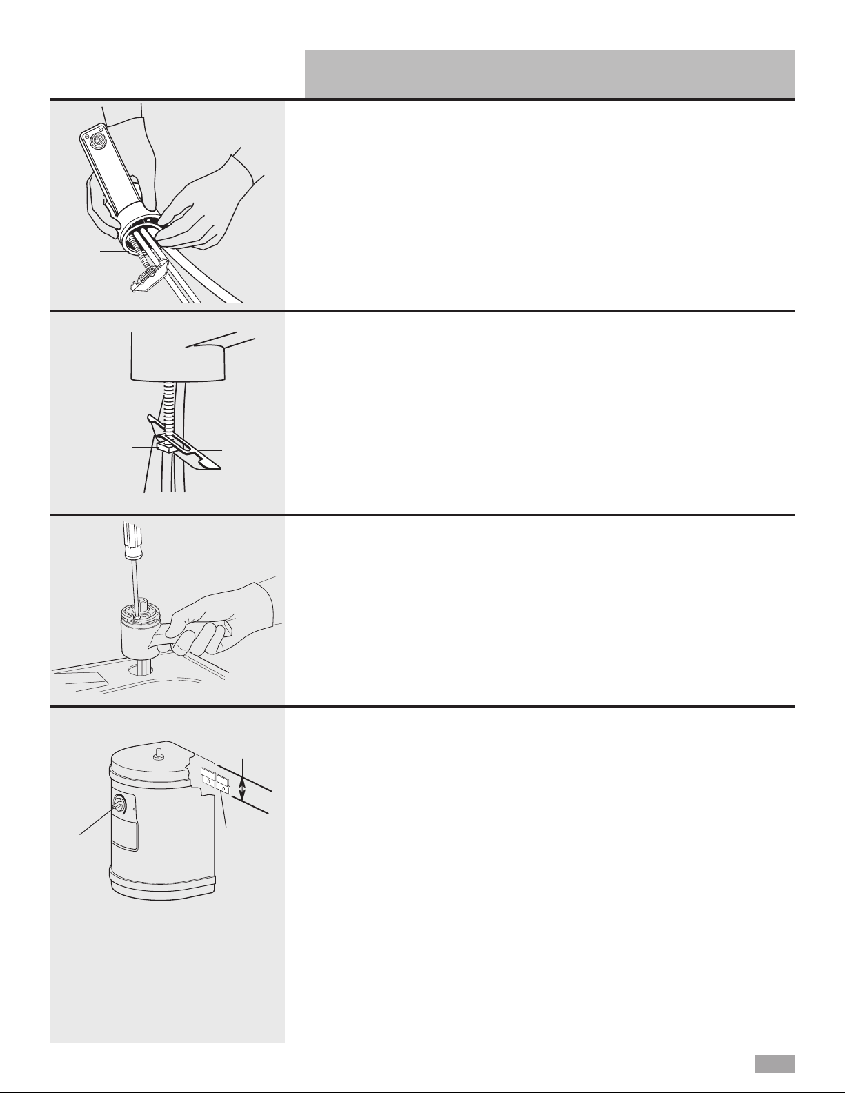
3.Remove masking tape and tag
from spout assembly. Do Not remove
quick-connect fittings from spout
tubing or tank tubing. Do not
replace quick-connect fittings with
brass fittings. Brass fittings can cause
lead contamination.
Carefully pull On/Off Cap off the
spout assembly and set aside.
Numbers
correspond
to steps.
2.
3.
7.
8.
9.
10.
11.
16.
12.
4.
5.
5.
13.
14.
15.
6.
flexible
tubing
off
position
NOTE: Do NOT plug power supply cord into outlet.
13.
On/Off Cap
1.Put on gloves and safety glasses.
Installation Instructions
Page 7
7
7.Position tank ver tically beneath
spout so that flexible tubing from
spout reaches center stainless tubing
on tank, and tank touches wall. Use a
pencil to mark on the wall where the
top of tank needs to be located. Set
tank aside. Mark a second line 2-1/4"
(5.7 cm) below the first line.
Note:The tank must be positioned
so that the flexible tubing to the
faucet does not kink.
Position mounting bracket on wall so
that bottom of mounting bracket is
even with the lower line. Use two
screws (and plastic anchors if
attaching to dry wall) to fasten
mounting bracket to wall.Hang tank
on bracket.
5.Loosen square nut until it is
flush with end of the mounting screw.
Tip spout bracket against mounting
screw. (Bracket will form a “y” when
in the correct position.)
Hold nut, bracket, gasket and tubing
in position and insert into hole in sink
or counter.
mounting
screw
square
nut
bracket
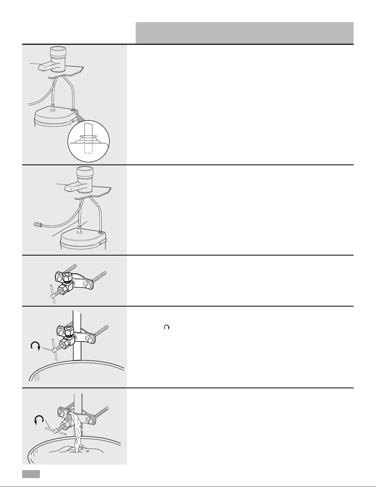
6.Pull up on spout body to keep
tension on spout mounting bracket
and nut.Tighten screw inside the
spout until spout is securely in
position. Do not overtighten. Snap
on On/Off Cap.
4.Lay spout assembly on flat
surface with coiled tubing facing up.
Using one hand to hold tubing just
below spout, carefully straighten
tubing with other hand. Slide gasket
over tubing so that lip side of gasket
is seated into base of spout.
gasket
bracket
2-1/4"
(5.7 cm)
off
position
NOTE: Do NOT plug power supply cord into outlet.
Installation Instructions cont.
Page 8
8
9.Connect flexible tubing from
spout to center tank tubing using
clamp. Make sure flexible tubing
does not kink.
The flexible tubing may be shor tened
if necessary.
10.Install saddle valve following
kit instructions. If water supply line is
not copper, shut off water supply and
drain line. Drill a 1/4" (6.4 mm) hole
into water supply line for the saddle
valve piercing pin.
11.Turn saddle valve handle
clockwise until lance pierces soft
copper tubing and valve is firmly
seated. If the water line is not copper,
turn the saddle valve handle
clockwise until the valve is firmly
seated.The valve is now in the
closed position.
Place a bucket under open end of
water supply line.Turn on main water
supply valve to pressurize cold water
line. Check for leaks.
12.Slowly open saddle valve and
flush line into bucket to remove any
foreign material that may have been
trapped in the supply line during
saddle valve installation.
Close saddle valve.
8.Connect 1/4" (6.4 mm) spout
tubing (longer tubing) to the rear
quick-connect fitting on top of tank.
Push tubing straight into fitting as far
as it will go.Pull on tubing. The
tubing should not come out when
properly installed.
Do Not lengthen, twist or tightly
bend tubing.
NOTE: If you need to remove tubing,
push down on collet. Pull tubing out
of quick-connect fitting.
quick-
connect
fitting
collet
flexible
tubing
clamp
closed
open
NOTE: Do NOT plug power supply cord into outlet.
Installation Instructions cont.
Page 9
9
copper
tubing
quick-connect
fitting
water supply
line
saddle
valve
13.Connect water supply line
from saddle valve to spout copper
tubing with the factory-assembled
quick-connect fitting. Push water
supply line tubing straight into fitting
as far as it will go. Pull on tubing.
The tubing should not come out
when properly installed.Turn the
saddle valve handle counterclockwise
to open water line.
NOTE: If you need to remove tubing,
push down on collet. Pull tubing out
of quick-connect fitting.
On
14.Turn Temperature Control
counterclockwise to “Off” position.
15.Push down and turn the
On/Off Cap clockwise to open spout.
Hold cap open to fill tank (about 1
minute).When tank is full, water will
flow from spout. Release cap.
16.Plug power supply cord into
grounded 3-prong outlet.
Turn Temperature Control clockwise
to highest position.
Water in tank will reach maximum
temperature in approximately
15 minutes.
When water is heating, you may hear
gurgling noises coming from the tank.
There may also be some spitting or
hot water flow from the faucet.This is
normal for the initial heat-up of the
dispenser.
Turn Temperature Control to lower
temperature setting if you notice
vapor or hear boiling noise.
NOTE:Temperature Control
controls tank heater, not water
delivery . Rotate Temperature
Control clockwise to raise water
temperature, counterclockwise to
lower water temperature.
NOTE: Do NOT plug power supply cord into outlet.
NOTE:T urn Temperature Control to
“Off” position before plugging hot
water dispenser into power supply.
If tank is empty and thermostat is
in an “On” position when the
power supply cord is connected,
the heater will overheat causing
an unpleasant taste, black specks
in the water, and permanent
damage to the heater seals.
Installation Instructions cont.
Page 10
10
Instant foods that require only 190°F (88°C) water for complete preparation
include:
Preparing instant foods and drinks
Cooking shortcuts
190°F (88°C) water will give you a fast start for any food you cook that requires
boiling water such as:
Other uses
loosening jar lids
peeling tomatoes or
peaches
dissolving gelatin
thawing frozen foods
preparing vegetables
for canning
coffee
tea
hot chocolate
soup or bouillon
mashed potatoes
instant cereal
frosting mix
packaged dinners
fresh or frozen
vegetables
dried soup
meat cooked in
liquid
hot cereals
pasta and rice
boiling eggs
Check that installation steps 14-16
were completed.
The hot water dispenser can be
permanently damaged if these steps
are not followed.
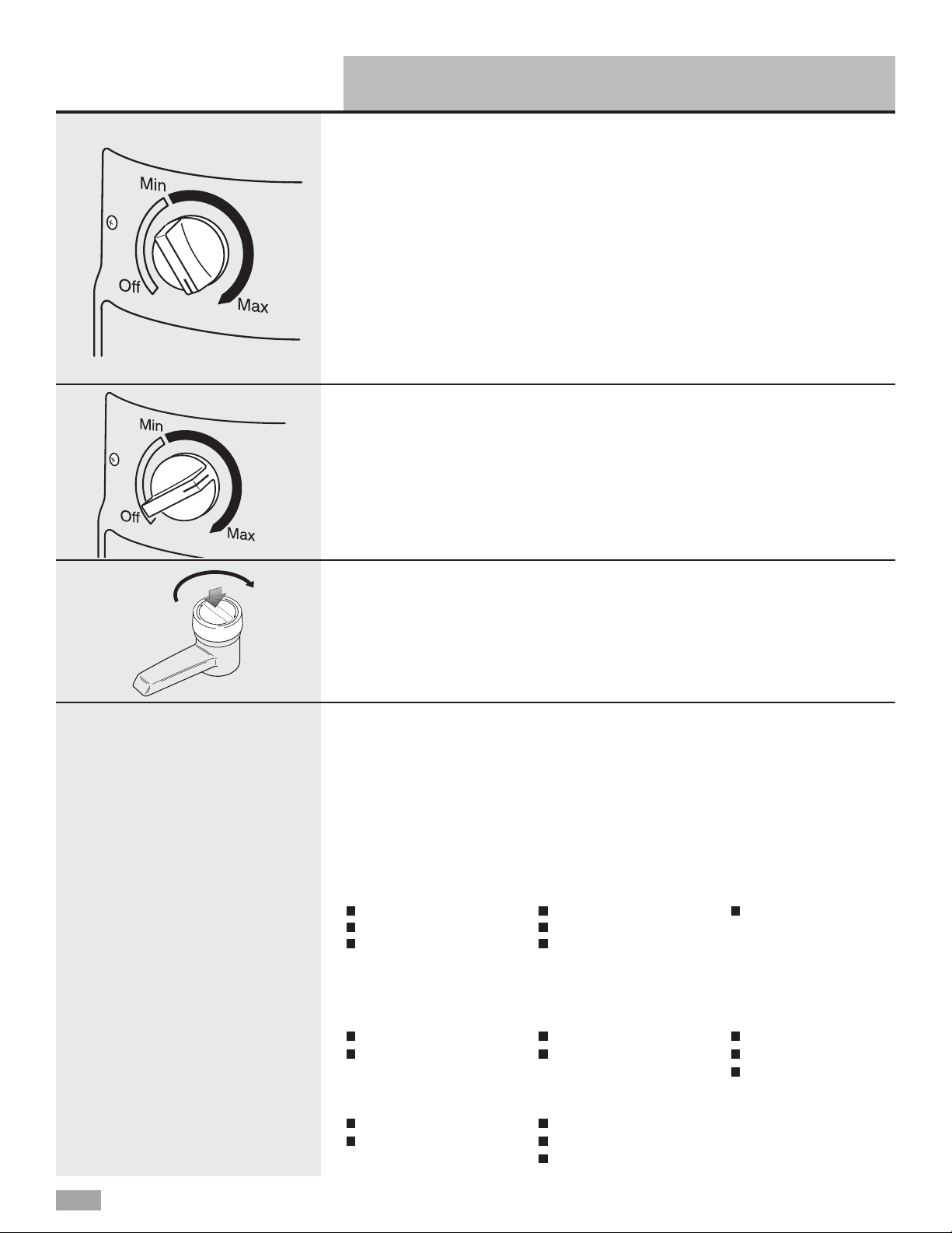
Push down and turn the On/Off Cap
clockwise and hold until desired
amount of hot water is obtained.You
can control the flow of water by how
far you turn the cap.For maximum
flow, turn cap until it stops. Release
the On/Off Cap to turn off water.
Before using the first time
Temperature control
The water temperature is
thermostatically controlled. It can be
adjusted from “Off” to approximately
190°F (88°C).
To raise or lower the temperature,
turn the Temperature Control. The
“Max” setting is recommended for
best performance. However, under
certain conditions, it is possible for
the water to boil when the
Temperature Control is set at “Max.”
If you see any vapor or hear boiling,
turn Temperature Control to lower
temperature as necessary.
Hot water dispenser uses
Regardless of what food you are
preparing, you’ll appreciate the
convenience and time saved by your
hot water dispenser.The dispenser
allows you to draw the amount of hot
water you require [up to 2 quarts
(1.9 liters) at one time]. It eliminates
the need to heat a full teakettle for a
cup of hot water.
Dispensing hot water
Using Your Hot Water Dispenser
Page 11

11
1. Turn Temperature Control to
the “Off” position. Push down and
turn On/Off Cap clockwise and
run water until it is cold to avoid
possibility of burn.
2. Remove the two spout screws.
3. Remove spout base plate.
4. Pull the screen assembly out of
the hot water tube.
5. Use a small brush and vinegar to
remove hard-water deposit.
If deposit has hardened, soak in
vinegar for an hour or two. Then
use a brush to clean.
6. Replace screen assembly in tube.
Reattach plate back onto spout.
7. Turn Temperature Control to the
“Max” setting.The dispenser will
be ready in about 15 minutes.
Cleaning the spout screen
If you have very hard water, and you
notice that the water flow is reduced,
it may be necessary to clean the
spout screen.
Energy-saving tips and preparation for periods of
nonuse
On average, you will use your hot
water dispenser to heat 7 to 8 cups
(1.7 to 1.9 liters) of water per day.
This uses only 19 kilowatt-hours of
energy per month. So it is Not
necessary to turn off the hot water
dispenser each night to conserve
energy.
However, if the hot water dispenser
will not be used for an extended
period of time, follow these
instructions:
Set the Temperature Control to the
“Off” position to conserve energy.
For short periods (2-30 days of nonuse):
screws
base plate
Caring For Your Hot Water Dispenser
O-ring
screw
For long periods of
nonuse (winterizing,
seasonal storage or
protection from freezing):
1. Turn Temperature Control to the
“Off” position.
2. Unplug hot water dispenser power
supply cord.
3. Turn On/Off Cap, hold and run
water until water is cold.
4. Turn saddle valve handle
clockwise to turn off water supply.
5. Place a 3-quart (2.8 liter)
minimum container under the
drain plug at the bottom of the tank.
6. Use a screwdriver to remove the
screw and O-ring from the drain
tube.
7. Replace the screw and O-ring in
the drain tube opening.Tighten
the screw to reseal the drain.
When ready to use the dispenser
again, follow Installation
Instruction steps 14-16, page 9.
Do Not Turn Unit On If Tank Is
Empty. Damage to the unit will
result and is not covered by the
warranty.
Page 12

12
Has circuit breaker tripped or
house fuse blown?
Is power supply cord plugged
in?
Is the Temperature Control set
to the “Off” position?
Has the water supply been
turned off?
Is the electrical outlet
controlled by a switch?
Before calling for service...
✓
✓
✓
✓
✓
If hot water dispenser does not operate, check these points first:
If you need more help, check the char t below. This could save you the cost of a service call for a problem that is
not covered by the warranty.
PROBLEM CHECK THE FOLLOWING
Water is not hot.
Check that the circuit breaker is not tripped or the house fuse blown.
Check that power supply cord is plugged into electrical outlet.
Check if the electrical outlet is operated by a switch.The switch may
have turned power off.
Cold water in tank is still being heated.Wait 15 minutes and check
temperature again.
Check that the Temperature Control is set to the “Max” setting.
Hot water drips or sputters from
spout.
Vapor appears, dispenser
makes boiling water noises, or
water is too hot.
Leaking saddle valve.
Water does not flow from spout.
Water has a “rotten egg”taste.
Adjust Temperature Control to a lower setting that eliminates the vapor or
noise. If you live at a high altitude, you may need to lower the thermostat
setting to keep water from boiling.
Check that tubing is not bent or kinked.
Adjust Temperature Control to a lower setting that eliminates the drips or
sputters.
Check that spout screen is not clogged. See “Caring For Your Hot Water
Dispenser,” Page 11.
Check for proper installation of copper tubing from spout to storage tank
and from spout to cold water line. See “Installation Instructions,” Pages 8-9.
Check that water supply valve is open.
Check that spout screen is not clogged. See “Caring For Your Hot Water
Dispenser,” Page 11.
If a water filter is used, check that water pressure to hot water dispenser
is 20 psi (138 kPa) minimum.
Tighten saddle valve clamp screws evenly and firmly. Keep both halves
of bracket parallel.Do Not crush water supply tubing.
Hot water dispenser is attached to hot water line.Attach to cold water line.
Install a water filtration system on cold water line to dispenser.
Troubleshooting
Page 13

13
Call the KitchenAid Customer Interaction
Center toll-free at 1-800-422-1230 or visit
www.kitchenaid.com.
Our consultants are available to assist you.
When calling: Please know the purchase date, and the
complete model and serial number of
your appliance (see the “A Note to You”
section). This information will help us
better respond to your request.
Our consultants provide assistance with:
•
Features and specifications on our full line
of appliances
•
Installation information
•
Use and maintenance procedures
If you need replacement parts
If you need to order replacement parts, we recommend
that you use only factory-authorized parts. These parts
will fit right and work right, because they are made to
the same exacting specifications used to build every
new KitchenAid®appliance.
To locate factory-authorized parts in your area, call our
Consumer Assistance Center telephone number, your
nearest authorized service center, or 1-800-442-9991.
For further assistance
If you need further assistance, you can write to
KitchenAid with any questions or concerns at:
KitchenAid Brand Home Appliances
Customer Interaction Center
553 Benson Road
Benton Harbor, MI 49022-2692
Please include a daytime phone number in your
correspondence.
•
Accessory and repair parts sales
•
Specialized customer assistance (Spanish speaking,
hearing impaired, limited vision, etc.)
•
Referrals to local dealers, service companies, and
repair parts distributors
KitchenAid service technicians are trained to fulfill the
product warranty and provide after-warranty service
anywhere in the United States.
To locate the authorized KitchenAid service company in
your area, you can also look in your telephone directory
Yellow Pages.
To avoid unnecessary service calls, please check the
“Troubleshooting Guide” section. It may save you the cost
of a service call. If you still need help, follow the
instructions below.
If you need assistance or service in U.S.A.
Requesting Assistance or Service
Page 14

14
2. If you need service✝...
Contact your nearest KitchenAid Canada Appliance
Service branch or authorized servicing outlet to
service your appliance. (See list below.)
Make sure the service company you contact is
authorized to service your appliance during the
warranty period.
1. If the problem is not due to one of the
items listed in “Troubleshooting Guide”
✝
...
Contact the dealer from whom you
purchased your appliance, or call the
KitchenAid Canada Consumer Assistance
Centre toll-free, 8:30 a.m. – 6 p.m. (EST),
at 1-800-461-5681 or visit
www.kitchenaid.com.
KitchenAid Canada Appliance Service – Consumer Services
Direct service branches:
BRITISH COLUMBIA 1-800-665-6788
ALBERTA 1-800-661-6291
ONTARIO Ottawa area 1-800-267-3456
(except 807 area code) Outside the Ottawa area 1-800-807-6777
MANITOBA,SASKATCHEWAN 1-800-665-1683
and 807 area code in ONTARIO
QUEBEC Montreal (except South Shore) 1-800-361-3032
South Shore Montreal 1-800-361-0950
Quebec City 1-800-463-1523
Sherbrooke 1-800-567-6966
ATLANTIC PROVINCES 1-800-565-1598
For further assistance
If you need further assistance, you can write to
KitchenAid Canada with any questions or concerns at:
Consumer Relations Department
KitchenAid Canada
1901 Minnesota Court
Mississauga, Ontario L5N 3A7
Please include a daytime phone number in your
correspondence.
✝
When asking for assistance or service, please
provide a detailed description of the problem,
your appliance’s complete model and serial
numbers, and the purchase date. (See the “A
Note to You” section.) This information will help
us respond properly to your request.
Before calling for assistance or service, please check the
“Troubleshooting Guide” section. It may save you the cost
of a service call. If you still need help, follow the
instructions below.
If you need assistance or service in Canada
Requesting Assistance or Service
Page 15

KITCHENAID AND KITCHENAID CANADA DO NOT ASSUME ANY RESPONSIBILITY FOR INCIDENTAL OR
CONSEQUENTIAL DAMAGES. Some states or provinces do not allow the exclusion or limitation of incidental or conse-
quential damages, so this exclusion or limitation may not apply to you.
This warranty gives you specific legal rights, and you may also have other rights which may vary from state to
state or province to province.
Outside the United States and Canada, a different warranty may apply. For details, please contact your
authorized KitchenAid dealer.
If you need service, first see the “Troubleshooting Guide” section of this book. After checking the “Troubleshooting Guide,”
additional help can be found by checking the “Requesting Assistance or Service” section or by calling our
Consumer Interaction Center, 1-800-422-1230 (toll-free), from anywhere in the U.S.A. or in Canada 1-800-461-5681.
LENGTH OF
WARRANTY:
ONE YEAR FULL
WARRANTY
FROM DATE OF
INSTALLATION
KITCHENAID
WILL NOT PAY FOR:
A. Service calls to:
1. Correct the installation of the Instant-Hot
Water Dispenser.
2. Instruct you how to use the Instant-Hot
Water Dispenser.
3. Replace house fuses or correct house
wiring.
4. Replace house plumbing.
B. Repairs when Instant-Hot Water Dispenser
is used in other than normal home use.
C. Damage resulting from accident, alteration,
misuse, abuse, improper installation, or
installation not in accordance with local
electrical codes or plumbing codes.
D. Replacement parts or repair labor costs for
units operated outside the United States.
E. Pickup and delivery. This product is
designed to be repaired in the home.
F. In Canada, travel or transportation expenses
for customers who reside in remote areas.
KITCHENAID
WILL PAY FOR:
Replacement parts and repair labor costs
to correct defects in materials or workmanship. Service must be provided by an
authorized KitchenAid servicing outlet.
2/98
INSTANT HOT*Water Dispenser Warranty
®
15
Page 16

PART NO.3193348
Pièce N° 3193348
©2001 KitchenAid, U.S.A.
®Trademark of KitchenAid, U.S.A., KitchenAid Canada licensee in Canada.
®Marque de commerce de KitchenAid, U.S.A., KitchenAid Canada porteur de licence au Canada.
Printed in U.S.A.
Imprimé aux É.U.
Page 17

Note à l’utilisateur
Nous vous remercions de votre
achat d’un appareil ménager
KitchenAid
®
!
KitchenAid conçoit les meilleurs outils
pour la pièce la plus importante dans
votre maison. Nous avons préparé ce
guide d’utilisation et d’entretien pour
que votre appareil puisse vous fournir
de nombreuses années de service
sans problème.Il contient des
renseignements importants concernant
l’utilisation et l’entretien convenables et
en sécurité de votre nouvel appareil.
Veuillez le lire attentivement.
Veuillez également remplir et nous
retourner la carte ci-jointe
d’enregistrement du produit fournie
avec votre distributeur d’eau chaude.
Grâce à cette carte, nous pouvons
vous aviser de tout nouveau
renseignement concernant votre
distributeur d’eau chaude.
Pièce n° 3193348
®
Inscrivez les renseignements concernant votre modèle
Inscrivez les renseignements suivants à propos de votre distributeur d’eau
chaude pour pouvoir plus facilement obtenir de l’assistance ou un service au
besoin.Vous devrez connaître le numéro de modèle et le numéro de série
complet de l’appareil.Vous pouvez trouver cette information sur la plaque
signalétique.
Si vous avez besoin d’assistance ou de ser vice, consulter d’abord la section
«Diagnostic» dans cette brochure. Après avoir consulté la section «Diagnostic»
on peut également obtenir de l’aide à la section «Demande d’assistance ou de
service».
Constructeur/marchand
Adresse
Numéro de téléphone
Numéro de modèle
Numéro de série
Date d’achat
Date d’installation
(Voir la section «Pièces et caractéristiques» pour l’emplacement de la plaque
signalétique.)
Conserver cette brochure et la facture d’achat ensemble en lieu
sûr pour consultation ultérieure.
Instructions d’installation
et
Guide d’utilisation et d’entretien
IMPORTANT :
Lire et conserver ces instructions.
IMPORTANT :
Installateur : Remettre ce guide au
propriétaire.
Propriétaire : Conserver ce guide
pour référence ultérieure et pour
référence par l’inspecteur local des
installations électriques.
Distributeur
d’eau chaude
Instant Hot
®
Page 18

Table des matières
2
Note à l’utilisateur Couverture
Sécurité du distributeur d’eau
chaude . . . . . . . . . . . . . . . . . . . . .2
Pièces et caractéristiques . . . . .3
Fonctionnement de votre distributeur
d’eau chaude . . . . . . . . . . . . . . . . 3
Avant de commencer . . . . . . . . .4
Outillage et matériaux
nécessaires . . . . . . . . . . . . . . . . . .5
Accessoires fournis . . . . . . . . . . . .5
Alimentation électrique -
spécifications . . . . . . . . . . . . . . . .5
Alimentation en eau -
spécifications . . . . . . . . . . . . . . . .5
Utilisation de votre distributeur
d’eau chaude . . . . . . . . . . . . . . .10
Avant la première utilisation . . . . .10
Commande de la température . . .10
Distribution d’eau chaude . . . . . .10
Usages du distributeur d’eau
chaude . . . . . . . . . . . . . . . . . . .10
Entretien de votre distributeur
d’eau chaude . . . . . . . . . . . . . . .11
Conseils d’économie d’énergie et
préparation pour une période de non-
utilisation . . . . . . . . . . . . . . . . . . .11
Nettoyage du tamis de filtration du
robinet . . . . . . . . . . . . . . . . . . .11
Diagnostic . . . . . . . . . . . . . . . . .12
Demande d’assistance ou
de service . . . . . . . . . . . . . . . . .13
Garantie . . . . . . . . . . . . . . . . . . .15
Sécurité du distributeur d’eau chaude
AVERTISSEMENT : Pour réduire
le risque d’incendie, de choc
électrique ou de blessure
pendant l’usage du distributeur
d’eau chaude, suivre les
précautions fondamentales
suivantes :
• Brancher dans une prise à
3 alvéoles reliées à la terre.
• Ne pas ôter la broche de mise à
la terre.
• Ne pas utiliser un adaptateur.
• Ne pas utiliser un cordon de
rallonge.
• Interrompre le courant avant le
service.
IMPORTANTES
INSTRUCTIONS
DE SÉCURITÉ
Risque possible de décès ou de
blessure grave si vous ne suivez
pas les instructions.
D ANGER
Votre sécurité et celle des autres est très importante.
Nous donnons de nombreux messages de sécurité importants dans ce
manuel, et sur votre appareil ménager. Assurez-vous de toujours lire tous
les messages de sécurité et de vous y conformer.
Tous les messages de sécurité vous diront quel est le danger potentiel et
vous disent comment réduire le risque de blessure et ce qui peut se
produire en cas de non-respect des instructions.
Risque possible de décès ou de
blessure grave si vous ne suivez
pas immédiatement
les
instructions.
AVERTISSEMENT
Voici le symbole d’aler te de sécurité.
Ce symbole d’alerte de sécurité vous signale les dangers potentiels
de décès et de blessures graves à vous et à d’autres.
Tous les messages de sécurité suivront le symbole d’alerte de sécurité et le
mot «DANGER» ou «AVERTISSEMENT». Ces mots signifient :
Page 19

Pièces et caractéristiques
3
Utiliser cette illustration du
distributeur d’eau chaude pour
apprendre rapidement comment
installer et utiliser votre nouveau
distributeur d’eau chaude. Les
numéros de page sont indiqués
pour vous aider à trouver des
renseignements plus détaillés à
propos de cette caractéristique.
Tube
flexible
(Page 8)
Robinet
(Pages 6, 7, 11)
Bouton de
manoeuvre
(Pages 6, 7, 9, 10)
Canalisation
d’eau froide du
robinet/bride
de
branchement
(Page 9)
Commande
de la
température
(Pages 9, 10)
Canalisation d’eau
chaude du robinet
(Page 8)
Réservoir
(Page 7)
Raccord rapide
(Page 8)
L’eau est chauffée électriquement à
une température d’infusion/cuisson
de 88°C (190°F) par un réservoir
monté sous l’évier. Un thermostat
maintient l’eau à cette température
approximative. Quand vous tournez
le bouton de manoeuvre, l’eau froide
pénètre au fond du réservoir et force
l’eau chaude hors du robinet. Le
système est ventilé de telle sorte que
le réservoir n’est pas pressurisé.
Fonctionnement de votre distributeur d’eau chaude
Raccord rapide
(Page 9)
Plaque
signalétique
Bouchon de
l’orifice de
vidange
(Page 11)
Bride de montage
située derrière le
réservoir (Page 7)
Page 20

Avant de commencer
4
Prise de courant
électrique, située à
moins de 106,7 cm
(42 po) du réservoir
du distributeur d’eau
chaude.
On doit
installer le
réservoir
verticalement
.
Robinet de puisage
installé dans le trou de
passage du tuyau
d’aspersion, sur le bord
de l’évier.
Si le robinet de
puisage n’est pas
installé dans le trou
de passage du
tuyau d’aspersion
de l’évier,pratiquer
une ouverture de
2,7 cm (1 1/16 po)
min. - 3,5 cm
(1 3/8 po) max.
robinet et
bride de
branchement
Important : Respecter les dispositions
de tous les codes et règlements en
vigueur.
canalisation
d’eau froide
Inspecter l’emplacement où le
distributeur d’eau chaude sera
installé. C’est à l’installateur
qu’incombe la responsabilité de
réaliser une installation correcte.
Veiller à disposer de tout le matériel
nécessaire pour une installation
correcte. C’est à l’installateur
qu’incombe la responsabilité de
respecter les prescriptions des
spécifications d’installation et des
codes de plomberie local et
provincial.
Si le robinet de puisage n’est pas
installé dans le trou de passage du
tuyau d’aspersion, contacter un
installateur qualifié pour
déterminer la meilleure méthode
de perçage du trou permettant
l’installation du robinet de puisage
17,1 cm
(6 3/4 po)
14,3 cm
(5 5/8 po)
28,3 cm
(11 1/8 po)
Robinet de puisage : On doit
disposer sur le comptoir ou le bord
de l’évier d’un trou de diamètre 2,7
cm (1 1/16 po) à 3,5 cm (1 3/8 po).
Le robinet de puisage peut être
installé à la place du tuyau
d’aspersion de l’évier. Pour une autre
configuration d’installation, consulter
un installateur qualifié au sujet de la
meilleure méthode pour le perçage
d’un trou dans le rebord de l’évier ou
le comptoir.L’épaisseur du matériau à
percer ne doit pas dépasser 2,9 cm
(1 1/8 po).
On doit disposer d’un moyen de
raccordement à la canalisation
d’eau froide. (Voir «Alimentation en
eau - Spécifications», page 5).
Une prise de courant électrique
reliée à la terre est nécessaire. (Voir
«Alimentation électrique Spécifications», page 5). La pr ise de
courant devrait être située à moins
de 106,7 cm (42 po) du réservoir du
distributeur d’eau chaude.
sur le comptoir ou le bord de l’évier.
Le raccordement à la canalisation
d’eau doit satisfaire les
prescriptions des codes de
plomberie et des règlements
sanitaires.
Ne pas entreposer ou faire
fonctionner le distributeur d’eau
chaude à une température inférieure
à 0°C (32°F).
Ne pas utiliser de composé
d’étanchéité des tuyaux. Un tel
composé pourrait pénétrer à
l’intérieur du distributeur et
constituer une source de goût ou
d’odeur désagréable.
Pour le raccordement à la
canalisation d’eau, utiliser des
raccords rapides ne nécessitant pas
l’emploi d’un composé d’étanchéité.
Avant de raccorder le distributeur
d’eau chaude au réseau électrique,
on doit le remplir d’eau et régler la
commande de température à la
position d’arrêt «OFF».
Ce distributeur d’eau chaude n’est
pas un purificateur d’eau. Certaines
installations peuvent nécessiter la
mise en place d’un système de
filtration pour l’amélioration de la
qualité de l’eau.
Épaisseur max. de
2,9 cm (1 1/8 po)
pour le matériau du
comptoir ou de
l’évier
Page 21

Avant de commencer - suite
règle ou mètreruban
pince
tournevis à
lame plate
Outillage et matériaux
nécessaires pour l’installation
Pièces fournies
clé(s) plate(s) pour la
bride/robinet
gants
5
perceuse
manuelle ou
électrique
seau ou bassine
coupe-tube
2 vis pour bride de montage (et
2 chevilles de plastique, si
fixation sur panneau de gypse)
Tube de cuivre, dia.
ext. 6,4 mm (1/4 po)
crayon
bride de
fixation du
réservoir
joint
réservoir
bride à tuyau
Retirer ces articles de leur
emballage.
Vérifier la présence de
tous les articles.
robinet de
puisage
foret de 6,4
mm (1/4 po)
robinet/bride de
branchement pour
raccordement à la
canalisation d’eau
L’ensemble doit satisfaire
les prescriptions de tous les
codes et règlements locaux.
lunettes
de
sécurité
Pour la sécurité des utilisateurs, il
faut que ce distributeur d’eau chaude
soit relié à la terre. Cet appareil est
équipé d’un cordon d’alimentation
électrique doté d’une fiche de
branchement à 3 broches, pour
liaison à la terre. Pour minimiser le
risque de choc électrique, on doit
brancher le cordon sur une prise de
courant murale à 3 alvéoles de même
configuration, reliée à la terre,
conformément aux prescriptions des
codes et règlements nationaux et
locaux. Si une pr ise de courant
murale de configuration appropriée
n’est pas disponible, c’est à
l’utilisateur qu’incombent la
responsabilité et l’obligation
personnelles de faire installer par un
électricien qualifié une prise de
courant murale à 3 alvéoles
correctement reliée à la terre.
Méthode recommandée pour
la liaison à la terre
Alimentation électrique Spécifications
Risque de choc électrique
Brancher dans une prise à 3
alvéoles reliée à la terre.
Ne pas ôter la broche de mise à
la terre.
Ne pas utiliser un adaptateur.
Ne pas utiliser un cordon de
rallonge.
Le non-respect de ces
instructions peut causer un
décès, un incendie ou un choc
électrique.
Si on utilise un conducteur distinct
de liaison à la terre lorsque le
code local le permet, il est
recommandé qu’un électricien
qualifié vérifie la qualité de la
liaison à la terre.
L’appareil doit être alimenté par un
circuit de 120 volts, 60 Hz, CA
seulement, protégé par fusible de 15
ou 20 A et relié électriquement à la
terre. Il est recommandé qu’un circuit
distinct soit utilisé seulement pour le
distributeur d’eau chaude. Utiliser une
prise qui ne peut être commandée
par un interrupteur.
Alimentation en eau - Spécifications
Si le code local le permet, on peut
raccorder le distributeur d’eau
chaude à la canalisation d’eau froide
à l’aide de l’ensemble robinet à
pointeau/bride de branchement.
Important : Si le code local ne
permet pas l’utilisation d’un
ensemble robinet/bride de
branchement, on doit utiliser un
dispositif de branchement avec
robinet spécial, disponible chez
les fournisseurs locaux d’articles
de plomberie.
On déconseille le raccordement de
l’appareil à une canalisation d’eau
chaude. Il y aurait un gaspillage
d’énergie car l’eau serait soumise à
deux opérations de chauffage - de
plus la barre de magnésium installée
dans le chauffe-eau de la résidence
pourrait produire un goût d’oeufs
pourris.
Si cet appareil remplace un
distributeur d’eau chaude raccordé à
une canalisation d’eau chaude, on
peut utiliser le branchement existant.
Un filtre est recommandé si votre
approvisionnement en eau contient
du sable, des granules ou autres
particules. Si un filtre est utilisé, la
pression de l’eau au distributeur ne
devrait pas baisser en-dessous de
138 kPa (20 lb/pi2).
fiche de
branchement à 3
broches, pour
liaison à la terre
prise de courant
murale à 3
alvéoles, reliée à
la terre
cordon
d’alimentation
broche de
liaison à
la terre
AVERTISSEMENT
Page 22

Instructions d’installation
6
1.Porter des gants et des lunettes
de sécurité.
2.Déterminer à quel emplacement
le distributeur d’eau chaude sera
installé. Inspecter l’espace sous
l’évier pour vérifier que les
composants de renforcement, brides
de support ou éléments de la
charpente des placards permettront
l’installation du robinet de puisage
sans interférence.Arracher l’opercule
du trou dans le rebord de l’évier, ou
percer un trou dans l’évier ou le
dessus du comptoir.
REMARQUE : S’il est nécessaire
de percer un trou dans l’évier ou le
comptoir, il est recommandé que
cette opération soit exécutée
uniquement par un plombier ou
installateur professionnel qualifié.
3.Enlever le ruban adhésif et
l’étiquette du robinet de puisage. Ne
pas enlever les raccords rapides
du tube d’alimentation du robinet
ou du réservoir. Ne pas remplacer
les raccords rapides par des raccords
en laiton. Les raccords en laiton
peuvent causer une contamination au
plomb.
Enlever prudemment le bouton de
manoeuvre du robinet et conserver
celui-ci en lieu sûr.
Les chiffres de
repérage
correspondent
aux étapes.
2.
3.
7.
8.
9.
10.
11.
16.
12.
15.
4.
5.
5.
13.
14.
15.
6.
tube
flexible
position
arrêt
NOTE: Ne PAS brancher le cordon d’alimentation dans une prise.
13.
Bouton de
manoeuvre
Page 23

Instructions d’installation - suite
7
bride
5,7 cm
(2-1/4 po)
7.Positionner le réservoir
verticalement sous le robinet de
puisage, de telle manière que le tube
flexible provenant du robinet atteigne
le tube de raccordement (acier
inoxydable) sur le réservoir, tandis
que le réservoir est en contact avec
le mur.Avec un crayon, marquer sur
le mur la limite supérieure de
l’emplacement d’installation du
réservoir.Retirer le réservoir.Tracer
une seconde ligne 5,7 cm (2 1/4 po)
plus bas que la première ligne.
Remarque : Le réser voir doit être
placé de telle sorte que le tube
flexible à raccorder au robinet ne
soit pas déformé.
Positionner la bride de montage sur
le mur de telle manière que le bas de
la bride de montage soit en
affleurement avec la ligne inférieure.
Fixer la bride sur le mur avec deux
vis (pour l’installation sur un panneau
de gypse, utiliser deux chevilles de
plastique). Suspendre le réservoir à
la bride.
5.Desserrer l’écrou carré et placer
celui-ci en affleurement avec
l’extrémité de la vis de montage.
Incliner la bride du robinet pour la
placer en contact avec la vis de
montage. (La bride forme un «y»
lorsque la position est correcte.)
Maintenir ensemble l’écrou, la bride,
le joint et le tube, et insérer
l’ensemble dans le trou percé dans
l’évier ou le comptoir.)
vis de
montage
écrou
carré
bride
6.Tirer sur le corps du robinet de
puisage pour maintenir la tension sur
la bride de montage et l’écrou. Serrer
la vis à l’intérieur du corps du robinet
pour immobiliser le robinet à la
position correcte. Ne pas serrer
excessivement. Emboîter le bouton
de manoeuvre.
4.Poser le robinet sur une surface
plane, le tube spiralé étant orienté
vers le haut. Avec une main, tenir le
tube juste au-dessous du robinet;
avec l’autre main, redresser
prudemment le tube. Enfiler le joint
par-dessus les tubes et placer la face
du joint comportant une lèvre en
contact avec la base du robinet.
joint
position
arrêt
NOTE: Ne PAS brancher le cordon d’alimentation dans une prise.
Page 24

Instructions d’installation - suite
8
9.Connecter le tube flexible
provenant du robinet au centre du
réservior au moyen de la bride.
Veiller à ce que le tube flexible ne
soit pas déformé.
Le tube flexible peut être raccourci
au besoin.
10.Installer l’ensemble
robinet/bride de branchement
conformément aux instructions
fournies. Si la canalisation d’arrivée
d’eau n’est pas faite de cuivre,
interrompre l’alimentation en eau et
purger la canalisation. Percer un trou
de 6,4 mm (1/4 po) dans la
canalisation d’eau pour le passage
du pointeau du robinet de
branchement.
11.Faire tourner dans le sens
horaire la manette du robinet de
branchement pour que le pointeau du
robinet perfore le tube de cuivre
de la canalisation d’eau et parvienne
à la position de butée.Si la
canalisation d’eau n’est pas en
cuivre, faire tourner dans le sens
horaire la manette du robinet de
branchement jusqu’à ce que le
robinet soit solidement installé. Le
robinet est alors fermé. Placer un
récipient sous l’extrémité ouverte du
tube d’alimentation du réservoir.
Ouvrir l’arrivée d’eau principale pour
pressuriser la canalisation d’eau
froide. Inspecter pour rechercher les
fuites.
12.Ouvrir lentement le robinet
de branchement et laisser l’eau
s’écouler dans le récipient en
entraînant les copeaux et débris qui
ont pu se former pendant l’installation
du robinet de branchement. Fermer
le robinet de branchement.
8.Connecter le tube plus long du
robinet, 6,4 mm (1/4 po) à l’arrière
sur le dessus du réservoir.Pousser le
tube en ligne droite dans le raccord
aussi loin qu’il ira.Tirer sur le tube.
Le tube ne devrait pas sortir quand il
est bien installé.
Ne pas allonger les tubes, ni les
vriller ou les plier.
tube
flexible
bride
fermé
ouvert
raccord
rapide
NOTE: Ne PAS brancher le cordon d’alimentation dans une prise.
Page 25

Instructions d’installation - suite
9
tube de
cuivre
raccord rapide
canalisation
d’eau
robinet/bride de
branchement
13.Exécuter le raccordement
entre le robinet de branchement et le
tube de cuivre du robinet de puisage
à l’aide d’un raccord rapide.Pousser
le tube de la canalisation d’eau en
ligne droite dans le raccord aussi loin
qu’il ira.Tirer sur le tube. Le tube ne
devrait pas sortir quand il est bien
installé.
Faire tourner dans le sens
antihoraire la manette du robinet
de branchement pour ouvrir la
canalisation d’eau.
REMARQUE : S’il est nécessaire
d’enlever le tube, appuyer sur la
virole.Tirer le tube hors du
raccord rapide.
Ouverture
14.Placer le bouton de la
commande de température à la
position d’arrêt (OFF) (rotation dans
le sens antihoraire).
15.Pour ouvrir le robinet,
enfoncer le bouton de manoeuvre et
faire tourner le bouton dans le sens
horaire. Maintenir le robinet ouvert
pour remplir le réservoir (environ 1
minute). Lorsque le réser voir est
plein, l’eau sort par le bec du robinet.
Lâcher le bouton de manoeuvre.
16.Brancher le cordon
d’alimentation sur une prise à 3
alvéoles reliée à la terre.
Faire tourner la commande de la
température dans le sens horaire à la
position de chauffage maximum.
L’eau présente dans le réservoir
atteindra sa température maximale
en 15 minutes environ.
Durant le chauffage de l’eau, vous
pouvez entendre un gargouillement
provenant du réservoir. Il est possible
qu’il y ait aussi du crachetage ou un
débit d’eau chaude au robinet. Ceci
est normal pour le chauffage initial
du distributeur.
S’il y a émission de vapeur ou de
bruit d’ébullition, régler la commande
pour une température moins élevée.
REMARQUE : La commande règle
la puissance de chauffage dans le
réservoir, et non pas dans le débit
d’eau. Pour augmenter la
température de l’eau, faire tourner
le bouton dans le sens horaire.
Pour réduire la température, faire
tourner le bouton dans le sens
antihoraire.
REMARQUE : Faire tourner la
commande de température à la
position «Arrêt» avant de brancher
le distributeur d’eau chaude dans
une prise de courant. Si le
réservoir est vide et que le
thermostat est à la position
«Marche» lorsque le cordon
d’alimentation est branché,
l’élément chauffant s’échauffera et
causera un goût déplaisant et des
taches noires dans l’eau et
endommagera en permanence les
joints du chauffe-eau.
NOTE : Ne PAS brancher le cordon d’alimentation dans une prise.
Page 26

Utilisation de votre distributeur d’eau chaude
10
Les aliments instantanés nécessitant
une eau à 88°C (190°F) pour une
préparation complète comprennent :
Préparation de boissons et d’aliments instantanés
Raccourcis de cuisson
L’eau à 88°C (190°F) vous donnera une avance rapide pour tout aliment à faire
cuire nécessitant de l’eau bouillante tel que :
Autres usages
desserrer les
couvercles de
bocaux
peler des tomates
ou pêches
dissoudre de la
gélatine
décongeler les
aliments
préparer des
légumes pour la
mise en conserve
café
thé
chocolat chaud
soupe ou bouillon
pommes de terre en
purée
céréales
instantanées
glaçage
repas emballés
légumes frais ou
congelés
soupe en poudre
viande cuite dans un
liquide
céréales chaudes
pâtes et riz
oeufs bouillis
Vérifier que les étapes 14 à 16 de
l’installation ont été achevées.
Le distributeur d’eau chaude peut
être endommagé en permanence si
ces étapes ne sont pas suivies.
Pour ouvrir le robinet, enfoncer le
bouton de manoeuvre et faire tourner
le bouton dans le sens horaire et le
maintenir ainsi jusqu’à l’obtention de
la quantité d’eau chaude désirée.
Vous pouvez contrôler le débit d’eau
en tournant plus ou moins le bouton
de manoeuvre. Pour un débit
maximum, faire tourner le bouton
jusqu’à la butée.Relâcher le bouton
de manoeuvre pour fermer l’eau.
Avant l’utilisation initiale
Commande de la température
La température de l’eau est contrôlée
par un thermostat. Il peut être réglé
de «Arrêt» (Off) à environ 88°C
(190°F).
Pour augmenter ou diminuer la
température, faire tourner la
commande de température. Le
réglage «Max» est recommandé pour
le meilleur rendement.Toutefois,
dans certaines conditions, il est
possible que l’eau se mette à bouillir
lorsque la commande de température
est réglée à «Max». Si vous
apercevez de la vapeur ou entendez
l’eau bouillir, tourner la commande
de la température au besoin pour
abaisser la température.
Usages du distributeur d’eau chaude
Peu importe le genre d’aliments que
vous préparez, vous apprécierez la
commodité et l’économie de temps
grâce à votre distributeur d’eau
chaude. Le distributeur vous permet
d’obtenir la quantité d’eau chaude
désirée jusqu’à 1,9 L - (2 pintes) à la
fois.Vous n’avez pas à faire chauffer
une bouilloire pleine pour obtenir une
tasse d’eau chaude.
Distribution d’eau chaude
Page 27

Entretien de votre distributeur
d’eau chaude
11
Nettoyage du filtre du robinet
Si vous avez une eau très dure et
remarquez que le débit d’eau est
réduit, il peut être nécessaire de
nettoyer le filtre du robinet.
Conseils d’économie d’énergie et préparation pour
une période de non-utilisation
En moyenne, on utilise le distributeur
d’eau chaude pour la production de
7 à 8 tasses (1,7 à 1,9 litre) d’eau
chaude par jour.Ceci suscite la
consommation de 19 kilowatt-heures
d’énergie par mois. Il n’est donc pas
nécessaire d’arrêter le système de
chauffage du distributeur chaque soir
pour économiser l’énergie.
Cependant, si le distributeur d’eau
chaude ne sera pas utilisé pendant
une période prolongée, exécuter les
instructions suivantes.
Placer la commande de température
du distributeur à la position d’arrêt
OFF, pour économiser l’énergie.
Pour une brève période de non-utilisation
(2 à 30 jours) :
vis
plaque de base
1. Faire tourner le bouton de réglage
de la température jusqu’à la position
de fermeture “Off”. Appuyer sur le
bouton de manoeuvre et faire tourner
le bouton dans le sens horaire.
Laisser couler l’eau jusqu’à ce qu’elle
soit froide, pour qu’il n’y ait plus
aucun risque de brûlure.
2. Dévisser les deux vis du robinet.
3. Ôter la plaque de base du robinet.
4. Tirer sur le filtre pour le sortir de
la canalisation d’eau chaude.
5. À l’aide de vinaigre et d’une petite
brosse, enlever les dépôts d’eau
dure. Si le dépôt a durci, le faire
tremper dans du vinaigre pendant
une heure ou deux, puis utiliser
une brosse pour le nettoyage.
6. Réinstaller le filtre dans la
canalisation. Reposer la plaque
sur le robinet.
joint torique
vis
Préparation pour une
longue période de nonutilisation (période
hivernale, remisage
saisonnier ou protection
contre le gel) :
1. Faire tourner le bouton de réglage
de la température jusqu’à la
position d’arrêt “Off”.
2. Débrancher le cordon
d’alimentation du distributeur d’eau
chaude.
3. Faire tourner le bouton de
manoeuvre; maintenir le bouton et
laisser l’eau couler jusqu’à ce
qu’elle soit froide.
4. Faire tourner dans le sens horaire
la manette du robinet de prise en
charge, pour fermer l’arrivée d’eau.
5. Placer un récipient, minimum 2,8
litres (3 pintes), sous le bouchon
de vidange au fond du réservoir.
6. À l’aide d’un tournevis, enlever la
vis et le joint torique du tube de
vidange.
7. Réinstaller la vis et le joint torique
dans l’ouverture du tube de
vidange. Serrer la vis pour assurer
l’étanchéité.
Lorsque vous êtes prêt à utiliser le
distributeur de nouveau, suivre les
étapes 14 à 16 des instructions
d’installation, à la page 9. Ne pas
allumer le distributeur si le
réservoir est vide.Vous risquez
d’endommager le distributeur et
ces dommages ne sont pas
couverts par la garantie.
Page 28

Diagnostic
12
Un fusible est-il grillé ou le
disjoncteur est-il ouvert?
Le cordon d’alimentation
électrique est-il branché?
La commande de la
température est-elle
réglée à la position
«Arrêt»?
Est-ce que l’alimentation
en eau a été fermée?
Est-ce que la prise murale
est commandée par un
interrupteur?
Avant de contacter le service de dépannage...
✓
✓
✓
✓
✓
Si le distributeur d’eau chaude ne fonctionne pas, vérifier d’abord les points suivants :
Si vous avez besoin d’aide supplémentaire, voir le tableau ci-dessous.Ceci pourrait vous faire économiser le coût
d’une visite de service pour un problème qui n’est pas couvert par la garantie.
Problème Solution
L’eau n’est pas chaude.
Déterminer si le disjoncteur est ouvert ou le fusible a grillé.
Vérifier que le cordon d’alimentation électrique est branché sur la prise de
courant murale.
Vérifier si la prise de courant murale est commandée par un interrupteur.
L’interrupteur a peut-être coupé le courant.
L’eau froide est encore en cours de chauffage dans le réservoir.Attendre 15
minutes et évaluer de nouveau la température.
Vérifier que la commande de température est réglée à «
Max
».
Écoulement ou projection de
gouttes d’eau par le robinet de
puisage.
Émission de vapeur, bruits
d’ébullition ou eau trop chaude.
Fuite au niveau du robinet de
branchement.
Aucun écoulement par le
robinet de puisage.
Eau avec goût d’oeufs pourris.
Régler la commande de température du distributeur d’eau chaude
pour une température moins élevée, qui ne suscite pas l’émission de
vapeur ou bruits. Si vous habitez à haute altitude, vous devrez peut-être
réduire le réglage du thermostat pour empêcher l’eau de bouillir.
Vérifier qu’aucun tube n’est plié ou écrasé.
Régler la commande de température pour une température moins élevée
qui ne suscite pas d’émission de gouttelettes ou projections.
Inspecter le tamis de filtration du robinet.Voir Entretien du distributeur
d’eau chaude, page 11.
Contrôler la qualité de l’installation des tubes de cuivre entre le robinet de
puisage et le réservoir et entre le robinet de puisage et la canalisation
d’eau froide.Voir «Instructions d’installation», pages 8-9.
Vérifier que le robinet d’arrêt principal est ouver t.
Inspecter le tamis de filtration du robinet.Voir Entretien du distributeur
d’eau chaude, page 11.
Si un filtre à eau est utilisé, vérifier que la pression d’eau au distributeur
d’eau chaude est d’au moins 138 kPa (20 lb/po2).
Serrer fermement et uniformément les vis de la bride d’installation du
robinet de branchement. Les deux moitiés de la br ide doivent être
parallèles.Veiller à ne pas déformer la canalisation d’alimentation.
Le distributeur d’eau chaude est alimenté sur une canalisation d’eau
chaude. Raccorder le distributeur à une canalisation d’eau froide.
Installer un système de filtration entre la canalisation d’eau froide et le
distributeur.
Page 29

Demande d’assistance ou de service
13
Contacter sans frais le centre d'assistance aux
consommateurs de KitchenAid au 1-800-422-1230,
ou consulter l’information du site Internet à
l’adresse www.kitchenaid.com.
Nos consultants sont prêts à vous aider.
Lors du contact :Veuillez communiquer la
date d’achat ainsi que le numéro de série
et le numéro de modèle complet de
l’appareil (voir la section «Note à
l’utilisateur»). Cette information nous
aidera à mieux satisfaire vos besoins.
Nos consultants vous renseigneront sur les sujets
suivants :
•
Caractéristiques et spécifications sur toute notre
gamme d’appareils ménagers.
•
Information pour l’installation
•
Procédures d’utilisation et d’entretien.
Pour acheter des pièces de rechange
Si vous avez besoin de commander des pièces de
rechange, nous recommandons l’emploi uniquement de
pièces autorisées par l’usine. Ces pièces seront
facilement installées et fonctionneront bien parce
qu’elles sont fabriquées avec la même précision mise
en oeuvre dans la fabrication de chaque appareil
ménager KitchenAid®neuf. Pour obtenir des pièces de
rechange autorisées par l’usine, contacter le Centre de
service autorisé le plus proche, ou composer le
1-800-442-9991.
Pour obtenir une assistance plus étendue
Si vous avez besoin d’une assistance plus étendue,
vous pouvez écrire à KitchenAid pour nous
communiquer vos questions ou préoccupations, à
l’adresse suivante :
KitchenAid Brand Home Appliances
Customer Interaction Center
553 Benson Road
Benton Harbor, MI 49022-2692
Dans votre correspondance, veuillez indiquer un
numéro de téléphone où on peut vous contacter dans
la journée.
•
Vente de pièces de rechange et accessoires.
•
Assistance spécialisée à la clientèle (langue
espagnole, malentendants, malvoyants, etc.).
•
Marchands locaux, entreprises de service et
distributeurs de pièces de rechange.
Les techniciens de service KitchenAid ont reçu la
formation qui leur permet d’effectuer les travaux de
réparation sous garantie et le service après-vente sur les
produits partout aux É.-U.
Vous pouvez également consulter l’annuaire
téléphonique Pages jaunes pour identifier une entreprise
de service autorisée KitchenAid dans votre région.
Avant de faire un appel pour assistance ou service,
consulter la section «Diagnostic». Ceci pourra peut-être
vous épargner le coût de la visite d’un dépanneur. Si une
aide demeure nécessaire, procéder conformément aux
instructions ci-dessous.
Demande d’assistance ou de service aux É.-U.
Page 30

14
2. Si vous avez besoin de services de dépannage
✝
...
Contactez la plus proche succursale de service de
KitchenAid Canada ou un centre de service autorisé pour
l’entretien de votre appareil ménager. (Voir liste cidessous.)
S’assurer que la compagnie de service contactée est
autorisée à effectuer l’entretien de votre appareil ménager
au cours de la période de garantie.
1. Si la cause du problème n’est pas
mentionnée à la section «Diagnostic»
✝
...
Contactez le marchand chez qui vous
avez acheté votre appareil ménager ou
téléphonez sans frais au Centre
d’assistance aux consommateurs de
KitchenAid Canada au 1-800-461-5681
entre 8 h 30 et 18 h (HNE), ou consultez
l’information du site Internet à l’adresse
www.kitchenaid.com.
Service d’appareils ménagers KitchenAid Canada Service aux consommateurs
Succursales de service direct :
COLOMBIE-BRITANNIQUE 1-800-665-6788
ALBERTA 1-800-661-6291
ONTARIO Région d’Ottawa 1-800-267-3456
(à l’exception de l’indicatif régional 807) À l’extérieur de la région d’Ottawa 1-800-807-6777
MANITOBA,SASKATCHEWAN 1-800-665-1683
et indicatif régional 807 en ONTARIO
QUÉBEC Montréal (à l’exception de la rive Sud) 1-800-361-3032
Rive Sud Montréal 1-800-361-0950
Québec 1-800-463-1523
Sherbrooke 1-800-567-6966
PROVINCES DE L’ATLANTIQUE 1-800-565-1598
Pour plus d’assistance
Si vous avez besoin de plus d’assistance, vous pouvez
faire part de vos questions ou préoccupations ˆ
KitchenAid Canada en écrivant à :
Service des Relations à la clientèle
KitchenAid Canada
1901 Minnesota Court
Mississauga, Ontario L5N 3A7
Veuillez inclure dans votre correspondance un numéro
de téléphone où on peut vous joindre le jour.
✝
Lorsque vous contactez le service de dépannage,
veuillez inclure une description détaillée du
problème, les numéros de modèle et de série, et la
date d’achat. (Voir la section «Note à l’utilisateur».)
Ces renseignements nous sont nécessaires pour
répondre rapidement à votre demande.
Avant de faire un appel pour assistance ou service,
consulter la section «Diagnostic». Ceci pourra peut-être
vous épargner le coût de la visite d’un dépanneur. Si une
aide demeure nécessaire, procéder conformément aux
instructions ci-dessous.
Demande d’assistance ou de service au Canada
Demande d’assistance ou de service
Page 31

®
KITCHENAID ET KITCHENAID CANADA DÉCLINENT TOUTE RESPONSABILITÉ AU TITRE DE DOMMAGES
SECONDAIRES OU INDIRECTS. Certaines provinces n’admettent pas l’exclusion ou la limitation de dommages
secondaires ou indirects. Par conséquent, cette exclusion ou limitation peut ne pas vous être applicable.
Cette garantie vous confère des droits juridiques spécifiques; vous pouvez également avoir d’autres droits, qui
peuvent varier d’une province à l’autre ou d’un État à un autre.
Hors des États-Unis et du Canada, une garantie différente peut être applicable. Pour les détails, contacter le
marchand autorisé KitchenAid.
En cas de besoin d’assistance ou d’un service, consulter d’abord la section «Diagnostic» de cette brochure. Après avoir
consulté la section «Diagnostic», on peut également trouver de l’aide supplémentaire dans la section «Demande
d’assistance ou de service» ou en téléphonant à notre Centre d'assistance aux consummateurs au 1-800-422-1230
(sans frais) de partout aux É.-U. ou au 1-800-461-5681 au Canada.
DURÉE DE LA
GARANTIE :
GARANTIE COMPLÈTE
D’UN AN
À COMPTER DE LA
DATE D’INSTALLATION.
KITCHENAID NE PAIERA PAS POUR :
A. Les visites d’un dépanneur pour :
1. Correction de l’installation du distributeur
d’eau chaude Instant-Hot.
2. Explications du fonctionnement du
distributeur d’eau chaude Instant-Hot.
3. Remplacement des fusibles ou correction
du câblage de la maison.
4. Correction du circuit de conduit de
plomberie de la maison.
B. Réparations lorsque le distributeur d’eau
chaude est utilisé autrement que dans une
application familiale.
C. Dommage résultant d’accident, altération,
mauvais usage, abus, installation
inappropriée ou installation non conforme
aux codes locaux d’électricité et de
plomberie.
D. Les coûts des pièces de rechange et de la
main-d’oeuvre pour les appareils utilisés en
dehors du Canada ou des É.-U.
E. Frais de transpor t de l’appareil. Ce produit
est conçu pour être réparé à domicile.
F. Au Canada, les frais de voyage ou de
transport dans le cas des clients qui habitent
dans des régions éloignées.
KITCHENAID PAIERA POUR :
Pièces de rechange et frais de maind’oeuvre pour l’élimination des vices de
matériau ou de fabrication. Les travaux
doivent être exécutés par le personnel
d’un établissement de service autorisé
KitchenAid.
2/98
Garantie du distributeur d’eau chaude INSTANT HOT
®
15
Page 32

Part No.3193348
Pièce N° 3193348
©2001 KitchenAid, U.S.A.
®Trademark of KitchenAid, U.S.A., KitchenAid Canada licensee in Canada.
®Marque de commerce de KitchenAid, U.S.A., KitchenAid Canada porteur de licence au Canada.
Printed in U.S.A.
Imprimé aux É.-U.
 Loading...