

KitchenAid 9760425A User Manual
9760425A
HOTTE D'ASPIRATION PRO-LINE
™
DE 36" (91,4 cm)
POUR CUISINE CONFIGURÉE EN ÎLOT
Instructions d’installation et Guide d’utilisation et d’entretien
36" (91.4 cm) PRO-LINE
™
SERIES ISLAND RANGE HOOD
Installation Instructions and Use and Care Guide
IMPORTANT: READ AND SAVE THESE INSTRUCTIONS.
FOR RESIDENTIAL USE ONLY.
IMPORTANT : LIRE ET CONSERVER CES INSTRUCTIONS.
POUR UTILISATION RÉSIDENTIELLE UNIQUEMENT.
IMPORTANT:
Installer: Leave installation instructions with the homeowner.
Homeowner: Keep installation instructions for future reference.
Save installation instructions for local inspector's use.
IMPORTANT :
Installateur : Remettre les instructions d'installation au propriétaire.
Propriétaire : Conserver les instructions d'installation pour consultation ultérieure.
Conserver les instructions d'installation pour consultation par l'inspecteur local.
Table of Contents/Table des matières.............................................................................2
2
RANGE HOOD SAFETY
TABLE OF CONTENTS
RANGE HOOD SAFETY . . . . . . . . . . . . . . . . . . . . . . . . . . . . . . .2
INSTALLATION REQUIREMENTS . . . . . . . . . . . . . . . . . . . . . . .4
Tools and Parts . . . . . . . . . . . . . . . . . . . . . . . . . . . . . . . . . . . . .4
Location Requirements . . . . . . . . . . . . . . . . . . . . . . . . . . . . .4
Venting Requirements . . . . . . . . . . . . . . . . . . . . . . . . . . . . . .5
Electrical Requirements . . . . . . . . . . . . . . . . . . . . . . . . . . . . .6
INSTALLATION INSTRUCTIONS . . . . . . . . . . . . . . . . . . . . . . . .7
Install Chimney Support . . . . . . . . . . . . . . . . . . . . . . . . . . . .7
Complete Chimney Support Installation . . . . . . . . . . . . . . . .8
Make Electrical Connection . . . . . . . . . . . . . . . . . . . . . . . . . .8
Install Chimney Covers . . . . . . . . . . . . . . . . . . . . . . . . . . . . .9
Install Range Hood . . . . . . . . . . . . . . . . . . . . . . . . . . . . . . .10
Complete Installation . . . . . . . . . . . . . . . . . . . . . . . . . . . . . .10
Check Operation . . . . . . . . . . . . . . . . . . . . . . . . . . . . . . . . .11
RANGE HOOD USE . . . . . . . . . . . . . . . . . . . . . . . . . . . . . . . . . .11
Operation . . . . . . . . . . . . . . . . . . . . . . . . . . . . . . . . . . . . . . .11
RANGE HOOD CARE . . . . . . . . . . . . . . . . . . . . . . . . . . . . . . . .12
Cleaning and Maintenance . . . . . . . . . . . . . . . . . . . . . . . . .12
Accessories . . . . . . . . . . . . . . . . . . . . . . . . . . . . . . . . . . . . .12
REQUESTING ASSISTANCE OR SERVICE . . . . . . . . . . . . . .13
RANGE HOOD WARRANTY . . . . . . . . . . . . . . . . . . . . . . . . . . .14
WIRING DIAGRAM . . . . . . . . . . . . . . . . . . . . . . . . . . . . . . . . . .15
You can be killed or seriously injured if you don't immediately
You
can be killed or seriously injured if you don't
follow
All safety messages will tell you what the potential hazard is, tell you how to reduce the chance of injury, and tell you what can
happen if the instructions are not followed.
Your safety and the safety of others are very important.
We have provided many important safety messages in this manual and on your appliance. Always read and obey all safety
messages.
This is the safety alert symbol.
This symbol alerts you to potential hazards that can kill or hurt you and others.
All safety messages will follow the safety alert symbol and either the word “DANGER” or “WARNING.”
These words mean:
follow instructions.
instructions.
DANGER
WARNING
TABLE DES MATIÈRES
SÉCURITÉ DE LA HOTTE DE CUISINIÈRE . . . . . . . . . . . . . .16
EXIGENCES D'INSTALLATION . . . . . . . . . . . . . . . . . . . . . . . .18
Outillage et pièces . . . . . . . . . . . . . . . . . . . . . . . . . . . . . . . . . .18
Exigences d'emplacement . . . . . . . . . . . . . . . . . . . . . . . . . .18
Exigences concernant l'évacuation . . . . . . . . . . . . . . . . . . .19
Spécifications électriques . . . . . . . . . . . . . . . . . . . . . . . . . .20
INSTRUCTIONS D'INSTALLATION . . . . . . . . . . . . . . . . . . . . .21
Installation du support de cheminée . . . . . . . . . . . . . . . . . .21
Achever l'installation du support de cheminée . . . . . . . . . .22
Raccordement électrique . . . . . . . . . . . . . . . . . . . . . . . . . . .22
Installation du cache-cheminée . . . . . . . . . . . . . . . . . . . . . .23
Installation de la hotte de cuisinière . . . . . . . . . . . . . . . . . .24
Achever l'installation . . . . . . . . . . . . . . . . . . . . . . . . . . . . . .25
Contrôle du fonctionnement . . . . . . . . . . . . . . . . . . . . . . . .25
UTILISATION DE LA HOTTE DE CUISINIÈRE . . . . . . . . . . . .26
Fonctionnement . . . . . . . . . . . . . . . . . . . . . . . . . . . . . . . . . .26
ENTRETIEN DE LA HOTTE DE CUISINIÈRE . . . . . . . . . . . . .26
Nettoyage et entretien . . . . . . . . . . . . . . . . . . . . . . . . . . . . .26
Accessoires . . . . . . . . . . . . . . . . . . . . . . . . . . . . . . . . . . . . .27
DEMANDE D'ASSISTANCE OU DE SERVICE . . . . . . . . . . . .28
GARANTIE DE LA HOTTE DE CUISINIÈRE . . . . . . . . . . . . . .29
SCHÉMA DE CÂBLAGE . . . . . . . . . . . . . . . . . . . . . . . . . . . . . .30

3
IMPORTANT SAFETY INSTRUCTIONS
SAVE THESE INSTRUCTIONS
WARNING: TO REDUCE THE RISK OF FIRE, ELECTRIC
SHOCK, OR INJURY TO PERSONS, OBSERVE THE
FOLLOWING:
■ Use this unit only in the manner intended by the
manufacturer. If you have questions, contact the
manufacturer.
■ Before servicing or cleaning the unit, switch the power off at
the service panel disconnecting means to prevent power
from being switched on accidentally. When the service
disconnecting means cannot be locked, securely fasten a
prominent warning device, such as a tag, to the service
panel.
■ Installation work and electrical wiring must be done by
qualified person(s) in accordance with all applicable codes
& standards, including fire-rated construction.
■ Sufficient air is needed for proper combustion and
exhausting of gases through the flue (chimney) of fuel
burning equipment to prevent backdrafting. Follow the
heating equipment manufacturer's guideline and safety
standards such as those published by the National Fire
Protection Association (NFPA), the American Society for
Heating, Refrigeration and Air Conditioning Engineers
(ASHRAE), and the local code authorities.
■ When cutting or drilling into wall or ceiling; do not damage
electrical wiring and other utilities.
■ Ducted systems must always be vented outdoors.
CAUTION: For general ventilating use only. Do not use
to exhaust hazardous or explosive materials and vapors.
CAUTION: To reduce risk of fire and to properly exhaust
air, be sure to duct air outside - do not vent exhaust air into
spaces within walls ceilings, attics, crawl spaces, or
garages.
WARNING: TO REDUCE THE RISK OF FIRE, USE ONLY
METAL DUCTWORK.
WARNING: TO REDUCE THE RISK OF A RANGE TOP
GREASE FIRE:
■ Never leave the surface units unattended at high settings.
Boilovers cause smoking and greasy spillovers that may
ignite. Heat oils slowly on low or medium settings.
■ Always turn hood ON when cooking at high heat or when
flameing food (i.e. Crepes Suzette, Cherries Jubilee,
Peppercorn Beef Flambé).
■ Clean ventilating fans frequently. Grease should not be
allowed to accumulate on fan or filter.
■ Use proper pan size. Always use cookware appropriate for
the size of the surface element.
WARNING: TO REDUCE THE RISK OF INJURY TO
PERSONS IN THE EVENT OF A RANGE TOP GREASE
FIRE, OBSERVE THE FOLLOWING:
a
■ SMOTHER FLAMES with a close fitting lid, cookie sheet, or
other metal tray, then turn off the gas burner or electric
element. BE CAREFUL TO PREVENT BURNS. If the
flames do not go out immediately, EVACUATE AND CALL
THE FIRE DEPARTMENT.
■ NEVER PICK UP A FLAMING PAN - you may be burned.
■ DO NOT USE WATER, including wet dishcloths or towels -
a violent steam explosion will result.
■ Use an extinguisher ONLY if:
– You know you have a class ABC extinguisher, and you
already know how to operate it.
– The fire is small and contained in the area where it
started.
– The fire department is being called.
– You can fight the fire with your back to an exit.
a
Based on "Kitchen Fire Safety Tips" published by NFPA.
■ WARNING: To reduce the risk of fire or electrical shock,
do not use this fan with any solid-state speed control
device.
4
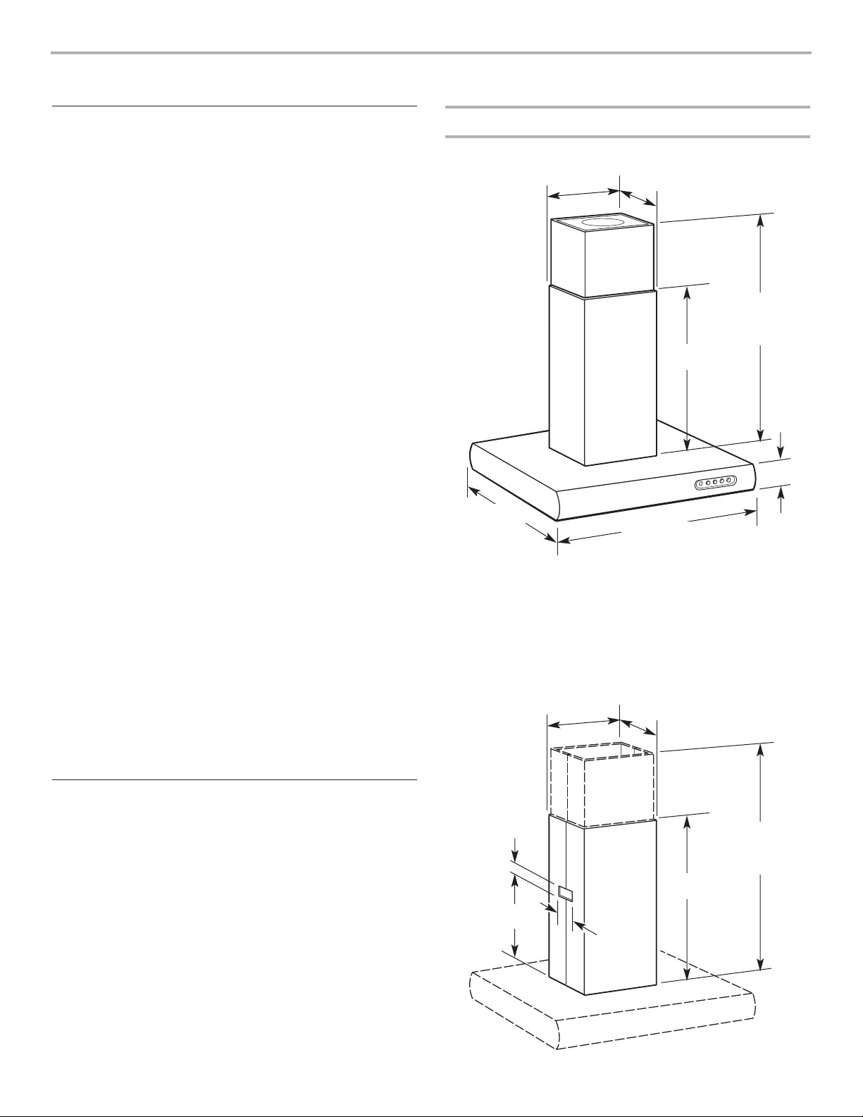
Product Dimensions
Location Requirements
IMPORTANT: Observe all governing codes and ordinances.
Island hood location should be away from strong draft areas,
such as windows, doors and strong heating vents.
Cabinet opening dimensions that are shown must be used. Given
dimensions provide minimum clearance.
Grounded electrical outlet is required. See “Electrical
Requirements” section.
It is recommended that the hood be fastened into solid wood.
The island hood is factory set for venting through the roof or wall.
For recirculating installations see “Recirculating Installations” in
“Install Chimney Covers” section.
All openings in ceiling and where island hood will be installed
must be sealed.
Tools and Parts
Gather the required tools and parts before starting installation.
Read and follow the safety instructions provided with any tools
listed here.
Tools needed:
■ level
■ drill with 1¹⁄₄" (3.0 cm) drill bit
■ pilot hole drill bit (determined by chimney support
attachment method)
■ pencil
■ wire stripper or utility knife
■ measuring tape or ruler
■ pliers
■ caulking gun and weatherproof caulking compound
■ duct tape
■ jig saw or keyhole saw
■ flat blade screwdriver
■ metal snips
■ Phillips screwdriver
Parts needed:
■ 2 UL- or CSA- listed, ¹⁄₂" (12.5 mm) strain reliefs
■ power supply cable
■ 1 wall or roof cap
■ metal vent system
■ 4, concrete anchors for ¹⁄₄" x 4" hex head lag bolts if
installing into concrete
Parts supplied:
Remove parts from packages. Check that all parts were included.
■ hood canopy assembly with ventilator and light bulbs installed
■ chimney assembly
■ ceiling template
■ Installation Instructions and Use & Care Guide
■ 3 filters
■ hardware package (4 wood shelf bolts, 4 wood shelf bolt
washers, 4 wood shelf nuts, 4 concrete plugs, 1 mounting
template, 1 damper)
INSTALLATION REQUIREMENTS
23
⁵⁄₈
"
(60.0 cm)
13
³⁄₄
"
(34.9 cm)
12
¹⁄₁₆
"
(30.6 cm)
4
³⁄₄
"
(12.1 cm)
35
³⁄₈
" (89.9 cm)
27
¹⁄₂
"
(69.9 cm)
26
³⁄₈
" (65.1 cm)
min.
39" (99.1cm)
max.
23
⁵⁄₈
"
(60.0 cm)
12
¹⁄₂
"
(31.8 cm)
3
¹⁄₂
"
(8.9 cm)
5"
(12.7 cm)
13
³⁄₄
"
(34.9 cm)
12
¹⁄₁₆
"
(30.6 cm)
32" (81.3 cm)
min.
39" (99.1 cm)
max.
Recirculating chimney kit dimensions
For recirculating installations, optional Recirculating Chimney Kit
No. 4396911 (Stainless Steel) or Kit No. 4396912 (Meteorite) must
be used. These kits include a new lower chimney cover (that
replaces the lower chimney cover shipped with the island hood),
a charcoal filter and a diverter.
5
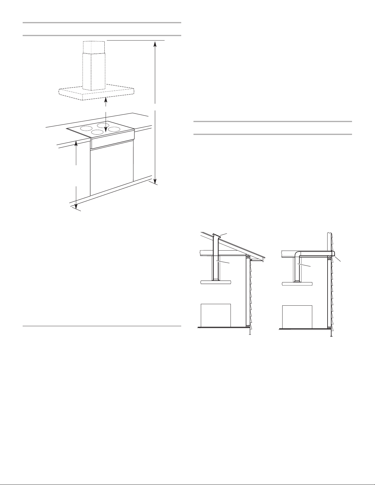
36" (91.4 cm)
typical
countertop
height
X
Installation Clearances
Venting Requirements
■ Vent system must terminate to the outside, except for the
recirculating installation.
■ Do not terminate the vent system in an attic or other enclosed
area.
■ Do not use 4" (10.2 cm) laundry-type wall caps.
■ Use 6" (15.2 cm) metal vent only. Rigid metal vent is
recommended. Do not use plastic or metal foil vent.
For the most efficient and quiet operation:
■ Use a straight run or as few elbows as possible.
■ Use no more than three 90° elbows.
■ Make sure there is a minimum of 24" (61 cm) of straight vent
between the elbows if more than one elbow is used.
■ Do not install two elbows together.
■ Use duct tape to seal all joints in the vent system.
■ Use caulking to seal exterior wall or roof opening around
the cap.
Cold weather installations
An additional backdraft damper should be installed to minimize
backward cold air flow and a nonmetallic thermal break to
minimize conduction of outside temperatures as part of the vent
system. The damper should be on the cold air side of the thermal
break.
The break should be as close as possible to where the vent
system enters the heated portion of the house.
Make-up air
Local building codes may require the use of make-up air systems
when using ventilation systems greater than specified CFM of air
movement. The specified CFM varies from locale to locale.
Consult your HVAC professional for specific requirements in your
area.
Venting Methods
This hood is factory set for venting through the roof or wall.
A 6" (15.2 cm) round vent system is needed for installation (not
included). The hood exhaust opening is 6" (15.2 cm) round.
NOTE: Flexible vent is not recommended. Flexible vent creates
back pressure and air turbulence that greatly reduces
performance.
Vent system can terminate either through the roof or wall. To vent
through a wall, a 90° elbow is needed.
A 6" (15.2 cm) round vent system length should not exceed
35 feet (10.7 m).
For recirculating installations see “Recirculating Installations” in
“Install Chimney Covers” section.
Roof venting
roof cap
wall
cap
6"
(15.2 cm)
round vent
Wall venting
6"
(15.2 cm)
round vent
see NOTE
NOTE: The hood chimneys are adjustable and designed to meet
varying ceiling or soffit heights depending on the distance “X”
between the bottom of the hood and the cooking surface. For
higher ceilings, a 40" (101.6 cm) Chimney Extension Kit No.
4396913 (Stainless Steel) or Kit No. 4396914 (Meteorite) is
available. See your dealer. The chimney extension replaces the
upper chimney shipped with the hood.
IMPORTANT:
Minimum distance “X”: 24" (61.0 cm)
Suggested maximum distance “X”: 30" (76.2 cm)
For vented installations, the chimneys can be adjusted for ceilings
between 7' 7¹⁄₈" (2.31 m) and 9' 1³⁄₄" (2.79 m).
For recirculating installations, the chimney can be adjusted for
ceilings between 8' 3³⁄₈" (2.52 m) and 9' 5¹⁄₄" (2.88 m).
6
Electrical Requirements
IMPORTANT: The hood must be electrically grounded in
accordance with local codes and ordinances, or in the absence of
local codes, with the National Electrical Code, ANSI/NFPA 70,
latest edition, or Canadian Electrical Code, CSA C22.1.
If codes permit and a separate ground wire is used, it is
recommended that a qualified electrical installer determine that
the ground path is adequate.
A copy of the above code standards can be obtained from:
National Fire Protection Association
One Batterymarch Park, Quincy, MA 02269
CSA International
8501 East Pleasant Valley Road
Cleveland, Ohio 44131-5575
■ A 120-volt, 60-Hz, AC-only, 15-amp, fused electrical circuit is
required. A time-delay fuse or circuit breaker is also
recommended. It is recommended that a separate circuit
serving only this hood be provided.
■ Do not ground to a gas pipe.
■ Check with a qualified electrician if you are not sure range
hood is properly grounded.
■ Do not have a fuse in the neutral or ground circuit.
■ The range hood must be connected with copper wire only.
■ The range hood should be connected directly to the fused
disconnect (or circuit breaker) box through flexible armored or
nonmetallic sheathed copper cable.
■ A UL- or CSA-listed strain relief must be provided at each end
of the power supply cable. Wire sizes (copper wire only) and
connections must conform with the rating of the appliance as
specified on the model/serial rating plate.
■ Wire sizes must conform to the requirements of the National
Electrical Code, ANSI/NFPA 70, latest edition, or CSA
Standards C22.1-94, Canadian Electrical Code, Part 1 and
C22.2 No. 0-M91, latest edition, and all local codes and
ordinances.
WARNING
Electrical Shock Hazard
Disconnect power before servicing.
Replace all parts and panels before operating.
Failure to do so can result in death or electrical shock.
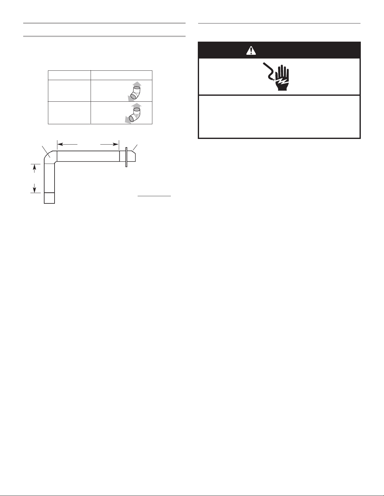
90° elbow
wall cap
1 — 90° elbow = 5 ft. (1.5 m)
8 ft. (2.4 m) straight = 8 ft. (2.4 m)
1 — wall cap = 0 ft. (0 m)
system length = 13 ft. (3.9 m)
6 ft. (1.8 m)
2 ft.
(0.6 m)
Example vent
system
Vent piece 6" (15.2 cm) round
45° elbow 2.5 feet
(0.8 m)
90° elbow 5.0 feet
(1.5 m)
NOTE: Flexible vent is not recommended. Flexible vent creates
back pressure and air turbulence that gently reduce performance.
Calculating Vent System Length
To calculate the length of the system you need, add the
equivalent feet (meters) for each vent piece used in the system.
Maximum equivalent vent length is 35 feet (10.7 meters).
7. Tape the template (supplied in the chimney support carton) to
the ceiling and mark the mounting holes, electrical hole and
vent location (if used) on the ceiling.
8. Drill pilot holes in the chimney support mounting hole
locations for your attachment method.
9. Use a 1¹⁄₄" or 3.0 cm drill bit to drill the hole for the power
supply cable.
10. If venting to the outside, cut the hole for the vent system in
the ceiling and install the vent system. See “Venting
Requirements” section.
11. If venting to the outside, place the round damper into the
exhaust opening of the vent motor housing.
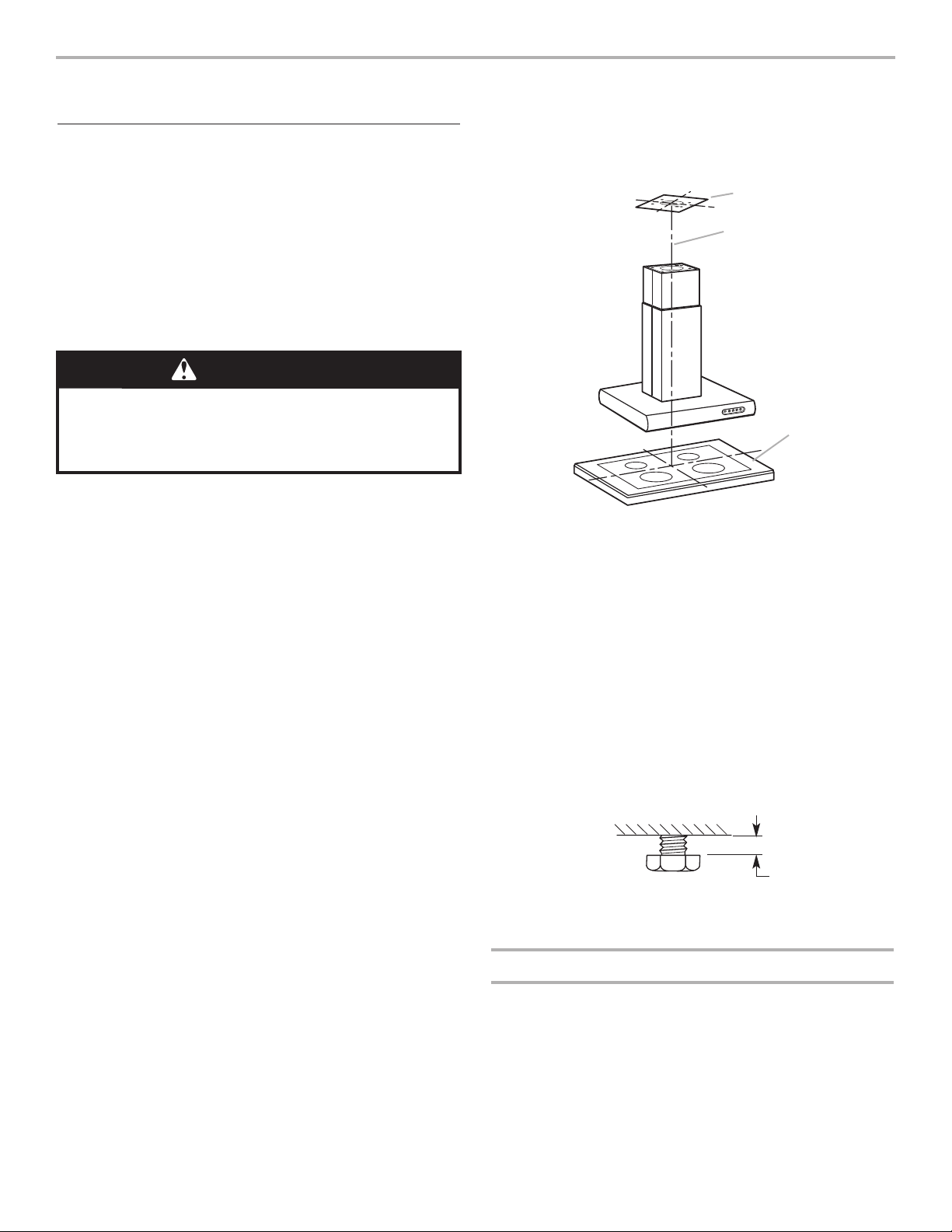
12. Remove the 4 chimney support ceiling attachment bolts from
the parts bag and install in previously drilled pilot holes. Leave
screw heads about ¹⁄₄" (6.4 mm) away from ceiling strips.
13. If the extension kit is not being installed, go to
“
Complete
Chimney Support Installation” section.
Installing Chimney Extension Kit (Optional)
1. Remove chimney extension cover (if factory assembled).
2. Position the chimney extension over the chimney support so
that the outside edges and the electrical holes line up.
INSTALLATION INSTRUCTIONS
Install Chimney Support
Because of the size and weight of this island hood, the chimney
support must be securely attached to the ceiling.
■ For plaster or drywall ceilings, the chimney support must be
attached to joists. If this is not possible, you must build a
support structure behind the plaster or drywall.
■ Do not cut a joist or stud unless absolutely necessary. If a
joist or stud must be cut, then a supporting frame must be
constructed.
■ Before making cutouts, make sure there is proper clearance
within the ceiling or wall for exhaust vent.
1. Select a flat surface for assembling the hood. Cover that
surface with a protective covering such as a blanket or
cardboard during assembly.
NOTE: Do not remove the plastic covering on the chimney
covers at this time. The covering protects the chimney during
installation.
2. Using two or more people, place all hood parts and hardware
on the protective covering
The chimney section of the hood is shipped assembled. It must
be disassembled for installation.
3. Slide apart the chimney covers.
4. Remove the lower chimney cover from the chimney support
by removing the two Phillips screws on the outside bottom of
the chimney cover.
5. Remove the upper chimney cover from the chimney support
by removing the two Phillips screws on the outside top of the
chimney cover.
6. Determine and mark the centerline on the ceiling where the
hood will be installed, making sure that the hood is centered
over the cooking surface.
WARNING
Excessive Weight Hazard
Use two or more people to move and install range hood.
Failure to do so can result in back or other injury.
A
B
C
A. Template on ceiling
B. Centerline
C. Cooking surface
¹⁄₄" (6.4 mm)
7
9. Replace the four screws and tighten securely.
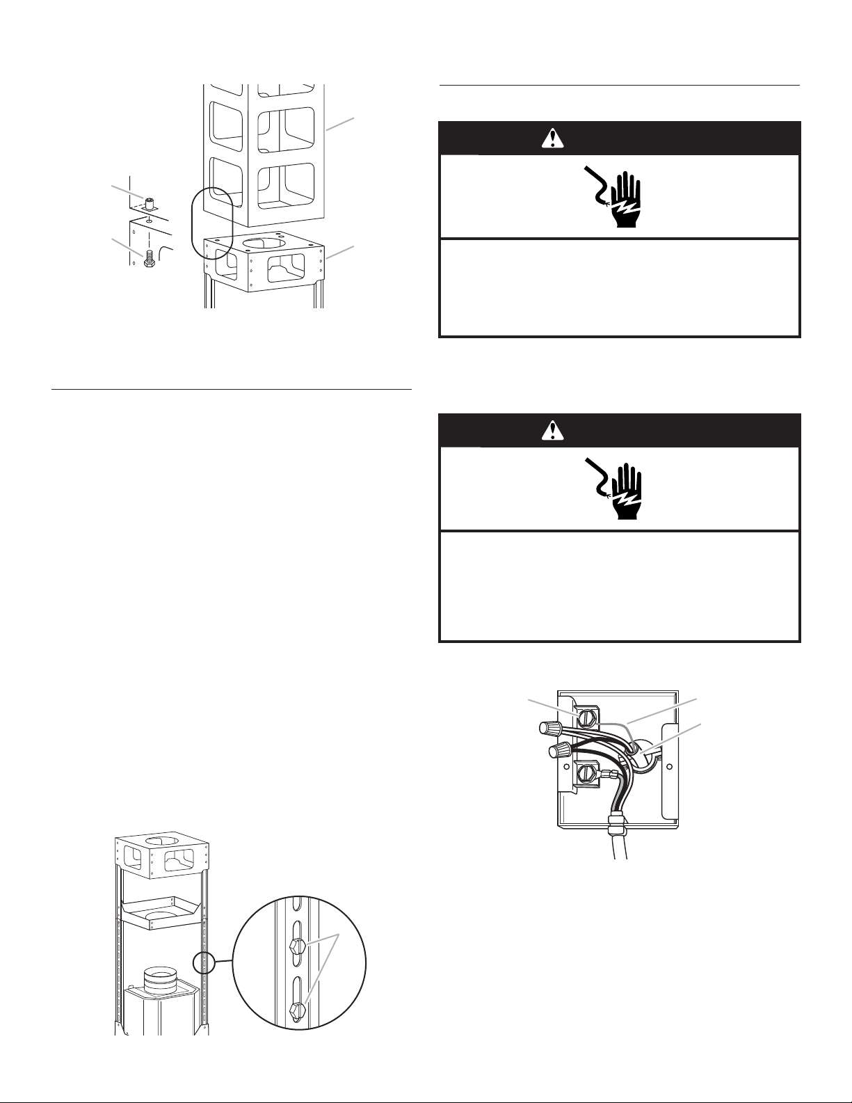
Make Electrical Connection
1. Disconnect power.
2. Use twist-on connectors and connect black wires together.
3. Use twist-on connectors and connect white wires together.
4. Connect ground wire to green ground screw in terminal box.
5. Tighten strain relief securely.
6. Replace wiring box cover. Tighten screw securely.
WARNING
Electrical Shock Hazard
Disconnect power before servicing.
Replace all parts and panels before operating.
Failure to do so can result in death or electrical shock.
C
A
B
A. Ground screw connector
B. Ground wire
C. Power supply cable
WARNING
Electrical Shock Hazard
Electrically ground blower.
Connect ground wire to green ground screw in
terminal box.
Failure to do so can result in death or electrical shock.
3. Attach the extension to the support using the 4 bolts supplied
with the extension kit. Tighten bolts securely.
Complete Chimney Support Installation
1. Run wire through the 1¹⁄₄" (3.0 cm) electrical hole in the ceiling
according to the National Electrical Code or CSA Standards
and local codes and ordinances. There must be enough
power supply cable from the fused disconnect (or circuit
breaker) box to make the connection in the hood’s electrical
wiring box.
2. Use caulk to seal all openings.
NOTE: Do not reconnect power until installation is complete.
3. Remove wiring box cover located on the top section of the
chimney support.
4. Install a UL- or CSA-listed strain relief in the wiring box so that
the screws can be tightened after the chimney support is
attached to the ceiling.
5. Lift chimney support into final position, feeding electrical wire
through the strain relief.
6. Position the chimney support so that the large end of the
keyhole slots are over the ceiling attachment bolts. Then push
the chimney support so that the bolts are in the neck of the
slots. Tighten bolts securely.
IMPORTANT: The chimney support must be securely
attached to the ceiling.
7. Determine the desired length of the chimney support.
8. Remove the four screws and adjust the length of the lower
chimney support as needed.
NOTE: This is the only section that can be adjusted.
A
B
C
D
A. Chimney extension frame
B. Chimney support
C. Bolt
D. Captive threaded insert
A
A. Screws
8
4. Install the two vent extension pieces onto the diverter, pushing
them until they stop.
5. Discard the lower chimney cover shipped with the hood and
use the cover from the Recirculating Kit (purchased
separately).
6. Slide the recirculating kit lower chimney cover over the
chimney support and the upper cover. Make sure the diverter
extensions line up with the openings in the cover. Attach the
cover using the two screws provided.
7. Snap vent grilles into place.
Chimney Extension Kit Installation (Optional)
1. Remove the plastic covering from the chimney covers.
2. Discard the upper chimney cover supplied with the hood.
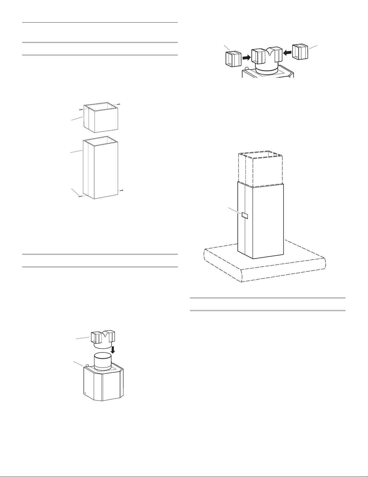
Install Chimney Covers
Vented Installation Option
1. Attach the vent system to the damper. Seal all joints with
duct tape.
2. Remove the plastic covering from the chimney covers.
3. Slide the upper chimney cover over the chimney support and
attach to the top of the support using two screws provided.
4. Slide the lower chimney cover over the chimney support and
the upper cover. Attach to the bottom of the support using
two screws provided.
Recirculating Installation Option, Kit Required
1. Remove the plastic covering from the chimney covers.
2. Slide the upper chimney cover over the chimney support and
attach to the top of the support using two screws provided.
3. Place the diverter from the Recirculating Chimney Kit over the
vent motor exhaust outlet and push down to seat on the
outlet. Make sure the diverter exhaust outlets are parallel with
the vent motor sides so that they will align with the vent cover
openings in lower chimney.
9
A
B
A
A. Vent extensions
A
A. Diverter
B. Vent motor
A. Upper chimney cover
B. Lower chimney cover
C. Screw
A
B
C
A
A. Vent grill location
10
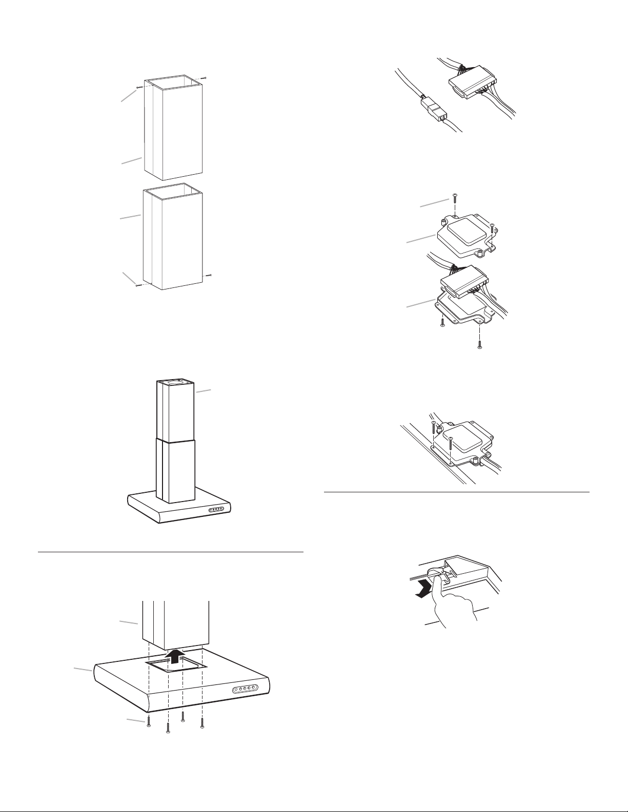
2. From the underside of the hood, plug control cables together
as shown.
3. Insert each connected cable into a black plastic connector
box half.
4. Place the top half of the connector box on each and screw
the two halves together using the four screws provided for
each connector box.
5. Using the two longer screws provided for each box, attach
the assembled connector boxes to the metal flange.
Complete Installation
1. For recirculating installations only, install charcoal filter from
Recirculating Chimney Kit behind the center grease filter by
inserting and locking it in place.
3. Slide the chimney cover provided with the extension kit over
the lower chimney support and extension frame and secure to
the top of the extension frame using the two screws provided.
4. Slide lower chimney cover over the chimney support and
extension chimney cover and attach to the bottom of the
support using the two screws provided.
Install Range Hood
1. Lift the hood up against the chimney support and attach to
the support with 4 bolts provided. Tighten bolts securely.
A. Screws
B. Connector box half
A
B
B
A. Screw
B. Upper chimney extension cover
C. Lower chimney cover
B
A
C
A
A
A
B
C
A. Chimney extension kit assembled to hood
assembly with chimney covers attached
A. Chimney support
B. Hood
C. Bolts
 Loading...