

KitchenAid 9755235 User Manual
HOME APPLIANCES
Tip Over Hazard
A cMId or adult can tip the range and be
kUled.
Connect anti-tip bracket to rear range foot.
Reconnect the anti-tip bracket, if the range
is moved.
Failure to follow these instructions can
result in death or serious burns to children
and adults.
®
R
Part No. 9755235 Rev. A
I
a
these _n,
IMPORTANT :
Installer: Leave Installation instructions
with the homeowner.
Homeowner: Keep Installation
instructions and anti-tip bracket
template for future reference.
Save Installation Instructions for local
electrical inspector's use.
O_So
30" (76.2 c
Seal urner
F in
m
n
with seff-cmeaning thermal/convection oven
Before you start...
Your safety and the safety of others
are very important.
Wehaveprovided many important safety messagesin
this manuaIand on your appliance. Always readand
obeyall safety messages.
This is the safety abrt symb0i.
This symb0t abrts you to potential hazards
that can kiii or hurt you and others.
Ati safety messageswiii f0ii0w the safety alert symbol
and either the word "DANGER"or "WARNING".These
words mean:
Youcan be kilbd or sed0usly injured ifyou don't
follow instructions.
AII safety messageswilI teli you what the p0tentiai
hazardis, teli you how to reduce the chance of injury,
and teii you what can happenif the instructions are not
followed.
WARNING: _fthe information in this
manual is not folmowed exactly, a fire
or explosion may resuJt causing
property damage, personal injury or
death.
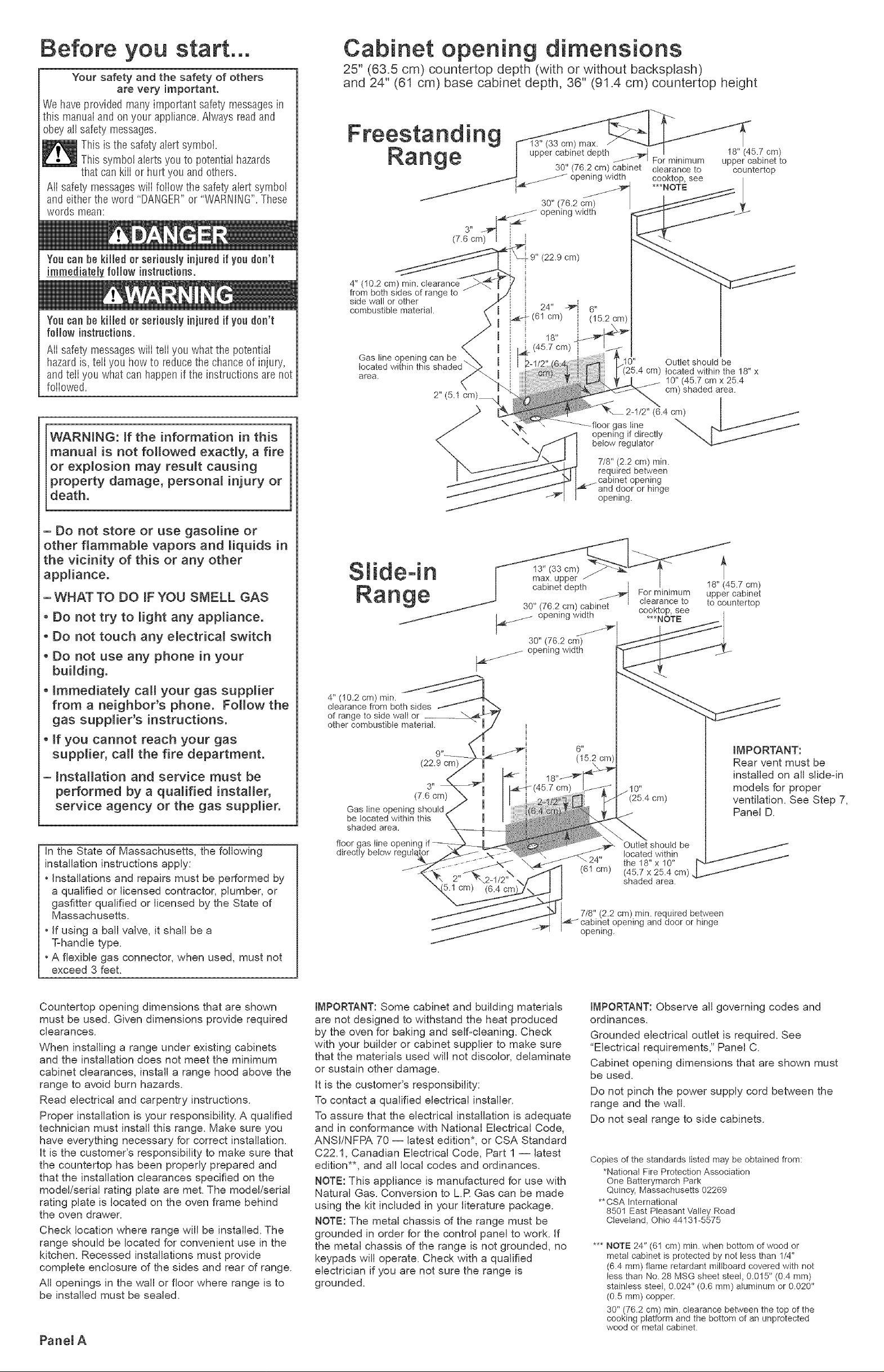
Cabinet opening dimensions
25" (63.5 cm) countertop depth (with or without backsplash)
and 24" (61 cm) base cabinet depth, 36" (91.4 cm) countertop height
Freestanding
Range
(7.6 cr_
4" (10.2 cm) rain. clearance
from both sides of range to
side wall or other
combustible material.
Gas tine opening can be
located within this
area.
upper cabinet depth _'_l
30" (76.2 cm)
|_ ,_ opening width
3"
(22.9 cm)
\
\
max. /
30" (76.2 cm) cabinet clearance to
opening width
For minimum
6"
! (15.2 cm)
.10" Outlet shoutd be
cm) located within the 18" x
10" (45.7 cm x 25.4
cm) shaded area.
2-1/2" (6.4 cm) I
floorgas,he
opening if directly _. I _- /
below regulator
7/8" (2.2 cm) rain.
required between
opening
and door or hinge
opening.
18" (45.7 cm)
upper cabinet to
countertop
I
- Do not store or use gasoline or
other flammabme vapors and liquids in
the vicinity of this or any other
appliance.
-WHAT TO DO iF YOU SMELL GAS
o Do not try to _ight any appliance.
o Do not touch any e_ectrica_ switch
o Do not use any phone in your
building.
o Immediately call your gas supplier
from a neighbor's phone. Follow the
gas supplier's instructions.
o if you cannot reach your gas
supplier, call the fire department.
- installation and service must be
performed by a qualified installer,
service agency or the gas supplier.
In the State of Massachusetts, the following
installation instructions apply:
• Installations and repairs must be performed by
a qualified or licensed contractor, plumber, or
gasfitter qualified or licensed by the State of
Massachusetts.
• If using a ball vaK,e, it shaft be a
T-handb type.
•A flexible gas connector, when used, must not
exceed 3 feet.
Slide-in
_j_._ opening width
4" (10.2 cm) rain.
clearance from both sides / I
of range to side wali or __ ",.,_.,_/"
other combustible matehal. " m,,"
¢
(22.9 cm)
(7.6 cm)
Gas line opening should
be tocated within this
shaded area.
floor gas fine opening
directly below
max. upper
cabinet depth _
30" (76.2 cm) cabinet
_ opening width
30" (76.2 cm)
(61 cm)
7/8" (2.2 cm) min. required between
opening.
For minimum
clearance to
cooktop, see
***NOTE
Outlet should be
located within
the 18" x 10"
(45.7 x 25.4 cm)
shaded area.
pening and door or hinge
18" (45.7 cm)
upper cabinet
to countertop
f
IMPORTANT:
Rear vent must be
instalbd on all slide-in
models for proper
ventilation. See Step 7,
Panel D.
Countertop opening dimensions that are shown
must be used. Given dimensions provide required
clearances.
When installing a range under existing cabinets
and the installation does not meet the minimum
cabinet clearances, install a range hood above the
range to avoid burn hazards.
Read electrical and carpentry instructions.
Proper installation is your responsibility. A qualified
technician must install this range. Make sure you
have everything necessary for correct installation.
it is the customer's responsibility to make sure that
the countertop has been properly prepared and
that the installation clearances specified on the
model/serial rating plate are met. The model/serial
rating plate is located on the oven frame behind
the oven drawer.
Check location where range wifl be installed. The
range should be located for convenient use in the
kitchen. Recessed installations must provide
complete enclosure of the sides and rear of range.
Aft openings in the wall or floor where range is to
be installed must be sealed.
Panel A
IMPORTANT: Some cabinet and building materials
are not designed to withstand the heat produced
by the oven for baking and self-cleaning. Check
with your builder or cabinet supplier to make sure
that the materials used will not discolor, delaminate
or sustain other damage.
It is the customer's responsibility:
To contact a qualified electrical instafler.
To assure that the ebctrical installation is adequate
and in conformance with National Electrical Code,
ANSI/NFPA 70 -- latest edition*, or CSA Standard
C22.1, Canadian Electrical Code, Part 1 -- latest
edition**, and all local codes and ordinances.
NOTE: This appliance is manufactured for use with
Natural Gas. Conversion to LR Gas can be made
using the kit included in your literature package.
NOTE: The metal chassis of the range must be
grounded in order for the control panel to work. If
the metal chassis of the range is not grounded, no
keypads will operate. Check with a qualified
electrician if you are not sure the range is
grounded.
IMPORTANT: Observe all governing codes and
ordinances.
Grounded ebctdcal outlet is required. See
"Electrical requirements," Panel C.
Cabinet opening dimensions that are shown must
be used.
Do not pinch the power supply cord between the
range and the wall.
Do not seal range to side cabinets.
Copies of the standards listed may be obtained from:
*National Fire Protection Association
One Batterymarch Park
Quincy, Massachusetts 02269
**CSA International
8501 East Pleasant'Valley Road
Cleveland, Ohio 44131-5575
*** NOTE 24" (6I cm) rain. when bottom of wood or
metal cabinet is protected by not less than 1/4"
(6.4 mm) flame retardant miltboard covered with not
tess than No. 28 MSG sheet steel, 0.015" (0.4 mm)
stainless steel, 0.024" (0.6 mm) aluminum or 0.020"
(0.5 ram) copper.
30" (76.2 cm) rain. clearance between the top of the
cooking platform and the bottom of an unprotected
wood or metal cabinet.

ran es:
for
countertop preparation
30 _
(76.2 cm)
opening,
width
1/2"
p"
30-7/8"
(78.4 cm) Formed or tiled countertop
. / trimmed 1/2" (1.3 cm)back
The cooktop sides of the siidedn range fit over
the cutout edge of your countertop.
if you have a square finish (flat) countertop and
the opening width is 30" (76.2 cm), no
countertop preparation is required.
Formed front-edged countertops: Must have
molded edge shaved flat 1/2" (1.3 cm) from
each front corner of opening.
Tile countertops may need trim cut back
1/2" (1.3 cm) from each front corner andlor
rounded edge flattened.
at front corners of
countertop opening.
(63.5 cm)
Cooktop sides of range fit over
edges of countertop opening.
if countertop opening width is greater than
30" (76.2 cm), adjust the 1/2" (1.3 cm) dimension.
Countertop must be level. Place level on
countertop, first side to side; then front to back.
if countertop is not level, range will not be level
Oven must be level for satisfactory baking
conditions.
ation:
Assemble the required tools and parts before starting
installation. Read and follow the instructions provided
with any tools listed here.
level
Phillips scewdriver
fiat-blade screwdriver or 5/16""(7.9 mm) nut driver
3/8" ( 9.5 mm) ratchet
adjustable wrench
pliers
hammer
measureing tape or ruler
hand or electric drill
wood floor: 1/8" (0.3 cm) drift bit
concrete/ceramic floor: 3/16" (0.48 cm)
carbide-tipped masonry drill bit
• LR gas conversion requires: pin pick up
(claw attachment)
• 5/16" nut driver
arts sup
for
uct dimensions
Freestanding Range
30" (76.2 cm)
range width
36-1/8"
(91.8 cm)
cooktop
height
44-3/8"
(112.7 cm)
-4
n:
• burner grates and caps
• vent cap
• LR conversion orifice spud kit:
1 - 0.95 mm (0.0374") cooktop (blue)
2 - 0.67 mm (0.0264") cooktop (black)
1 - 1.05 mm (0.0413") cooktop (green)
1 -#65 (0.0350") broil burner
anti-tig
plastic
anchors
(#10 x 1-1/2")
(Bracket must be securely mounted to sub-floor.
Thickness of flooring may require longer screws to
anchor the bracket to sub-floor.)
1-1/2"
(3.8 cm)
27-3/4"
(70.5 cm)
depth
with
handle
30" (76.2 cm) _1
rear vent width
Slide-in Range
]
36-1/8"
(91.8 cm)
cooktop
height
iMPORTANT:
Rear vent must be
installed on aJJ
slide-in models for
proper ventilation.
See Step 7, Panel D.
Mobile home installation
The installation of this range must conform to the
Manufactured Home Construction and Safety
Standards, Title 24 CFR, Part 3280 (formerly the
Federal Standard for Mobile Home Construction and
Safety, Title 24, HUD, Part 280); or when such
standard is not applicable, the Standard for
Manufactured Homes installations (Manufactured
Home Sites, Communities and Setups), ANSI
A225.1/NFPA 501A*, or with local codes.
In Canada, the installation of this range must conform
with the current standards CAN/CSA-Z240 -- latest
edition**, or with local codes.
When this range is installed in a mobile home, it must
be secured to the floor during transit. Any method of
securing the range is adequate as long as it conforms
to the standards listed above.
Copies of the standards listed may be obtained from:
* National Fire Protection Association
One Batterymarch Park
Quincy, Massachusetts 02269
**CSA International
8501 East Pleasant'Valley Road
Cleveland, Ohio 44131-5575
Panel B
(2.54 cm)
spacer
27-3/4"
(70.5 cm) ...
depth
with
handle
30 _
(76.2 cm)
width
The floor anti-tip bracket must
be installed. To install the anti-tip
bracket shipped with the range,
see Panel D and the anti-tip
bracket template.
 Loading...