

KitchenAid 9752913 Installation Instructions Manual

Tip Over Hazard
A child or adult can tip the range and be killed.
Connect anti-tip bracket to rear range foot.
Reconnect the anti-tip bracket, if the range is
moved.
Failure to follow these instructions can result in
death or serious burns to children and adults.
Quick Reference
Table of Contents:
Panels
IAl Before you start
0
A Product dimensions
IAl Cabinet dimensions/requirements
IAl Countertop preparation
q
Electrical requirements
m Ic] Installation steps
m If range does not operate
pGcLiq
If you need assistance/service
I] Moving the range
If you need assistance:
Check your Use and Care Guide for a toll-free number to call or call the
dealer from whom you purchased this appliance. The dealer is listed in
the Yellow Pages of your phone directory under “Appliances -
Household - Major - Service and Repair.”
Call when you:
j7J Have questions about range installation or operation.
q
Need to obtain the name and number of an authorized
service company.
When you call, you will need:
q
The range model number.
Q The range serial number.
S-98
Both numbers are listed on the model/serial rating plate located on the
oven frame behind the storage drawer panel.
Your safetv and the safetv
of others is’ very importank
We have provided many important safety
messages in this manual and on your
appliance. Always read and obey all safety
messages.
q
!
This is the safety alert symbol. This
symbol alerts you to hazards that can
kill or hurt you and others. All safety
messages will be preceded by the safety alert
symbol and the word “DANGER” or
“WARNING”. These words mean:
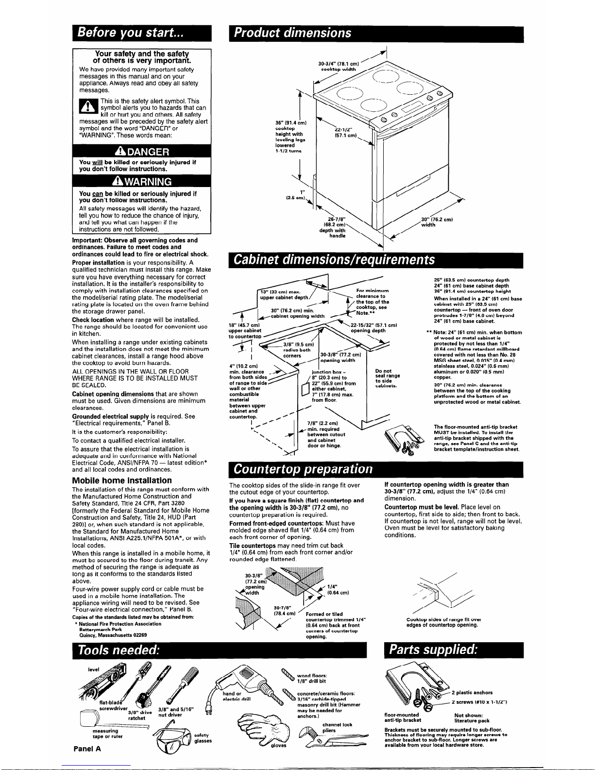
36” (91.4 c’m)
cooktop
height with
leveling legs
lowered
l-1/2 turns
12-l 12”
(57.1 cm)
Al
You &l be killed or seriously injured if
you don’t follow instructions.
You can be killed or seriously injured if
you don’t follow instructions.
All safety messages will identify the hazard,
tell you how to reduce the chance of injury,
and tell you what can happen if the
instructions are not followed.
(2.5 cm)
4
Important: Observe all governing codes and
ordinances. Failure to meet codes and
ordinances could lead to fire or electrical shock.
Proper installation is your responsibility. A
qualified technician must install this range. Make
sure you have everything necessary for correct
installation. It is the installer’s responsibility to
comply with installation clearances specified on
the model/serial rating plate. The model/serial
rating plate is located on the oven frame behind
the storage drawer panel.
Check location where range will be installed.
The range should be located for convenient use
in kitchen.
When installing a range under existing cabinets
and the installation does not meet the minimum
cabinet clearances, install a range hood above
the cooktop to avoid burn hazards.
ALL OPENINGS IN THE WALL OR FLOOR
WHERE RANGE IS TO BE INSTALLED MUST
BE SEALED.
Cabinet opening dimensions that are shown
must be used. Given dimensions are minimum
clearances.
Grounded electrical supply is required. See
“Electrical requirements,” Panel B.
It is the customer’s responsibility:
To contact a qualified electrical installer.
To assure that the electrical installation is
adequate and in conformance with National
Electrical Code, ANSVNFPA 70 - latest edition*
and all local codes and ordinances.
Mobile home installation
The installation of this range must conform with
the Manufactured Home Construction and
Safety Standard, Title 24 CFR, Part 3280
[formerly the Federal Standard for Mobile Home
Construction and Safety, Title 24, HUD (Part
28011 or, when such standard is not applicable,
the Standard for Manufactured Home
Installations, ANSI A225.1/NFPA 501A*, or with
local codes.
When this range is installed in a mobile home, it
must be secured to the floor during transit. Any
method of securing the range is adequate as
long as it conforms to the standards listed
above.
Four-wire power supply cdrd or cable must be
used in a mobile home installation. The
appliance wiring will need to be revised. See
“Four-wire electrical connection,” Panel B.
Copies of the standards listed may be obtained from:
* National Fire Protection Association
Batterymarch Park
Quincy, Massachusetts 02269
--” (76.2 cm) min.
25” (63.5 cm) countertop depth
24” (61 cm) base cabinet depth
36” (91.4 cm) countertop height
When installed in a 24” (61 cml base
cabinet with 25” (63.5 cm)
countertop - front of oven door
protrudes l-7/8” (4.8 cm) beyond
24” (61 cm) base cabinet.
Note: 24” (61 cm) min. when bottom
of wood or metal cabinet is
protected by not less than 114”
(0.64 cm) flame retardant millboard
covered with not less than No. 28
MSG sheet steel, 0.015” (0.4 mm)
stainless steel, 0.024” (0.6 mm)
aluminum or 0.020” (0.5 mm)
copper.
30” (76.2 cm) min. clearance
between the top of the cooking
platform and the bottom of an
unprotected wood or metal cabinet.
30-3/8” (77.2 cm)
I
l *
min. clearance
from both sides
of range to side
wall or other
combustible
material
between upper
cabinet and
8” (20.3 cm) to
22” (55.9 cm) from
either cabinet,
7” (17.8 cm) max.
Do not
seal range
to side
cabinets.
between cutout
The floor-mounted anti-tip bracket
MUST be installed. To install the
anti-tip bracket shipped with the
range, see Panel C and the anti-tip
bracket template/instruction sheet.
The cook-top sides of the slide-in range fit over
the cutout edge of your countertop.
If you have a square finish (flat) countertop and
the opening width is 30-3/B” (77.2 cm), no
countertop preparation is required.
Formed front-edged countertops: Must have
molded edge shaved flat l/4” (0.64 cm) from
each front corner of opening.
Tile countertops may need trim cut back
l/4” (0.64 cm) from each front corner and/or
rounded edge flattened.
If countertop opening width is greater than
30-3/8” (77.2 cm), adjust the l/4” (0.64 cm)
dimension.
Countertop must be level. Place level on
countertop, first side to side; then front to back.
If countertop is not level, range will not be level.
Oven must be level for satisfactory baking
conditions.
/ -..
/ ’
s
4
114’
(0.64 cml
Cooktop sides of range fit over
edges of countertop opening.
wood floors:
l/8” drill bit
concrete/ceramic floors:
3/16” carbide-tipped
masonry drill bit (Hammer
may be needed for
anchors.)
2 plastic anchors
2 screws (#IO x l-1/2”)
floor-mounted
Not shown:
anti-tip bracket
literature pack
Brackets must be securely mounted to sub-floor.
Thickness of flooring may require longer screws to
anchor bracket to sub-floor. Longer screws are
available from your local hardware store.
tape or ruler
Panel A
/
6F
%
safety
-‘v :,
h’
a
: z
. . ,I
glasses
gloves
channel lock
 Loading...