

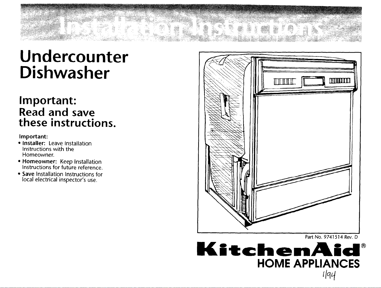
Undercounter
Dishwasher
Important:
Read and save
these instructions.
Important:
l
Installer: Leave Installation
Instructions with the
Homeowner.
l
Homeowner: Keep Installation
Instructions for future reference.
l
Save Installation Instructions for
local electrical inspector’s use.
Part No. 97415 14 Rev. D
HOME APPLIANCES
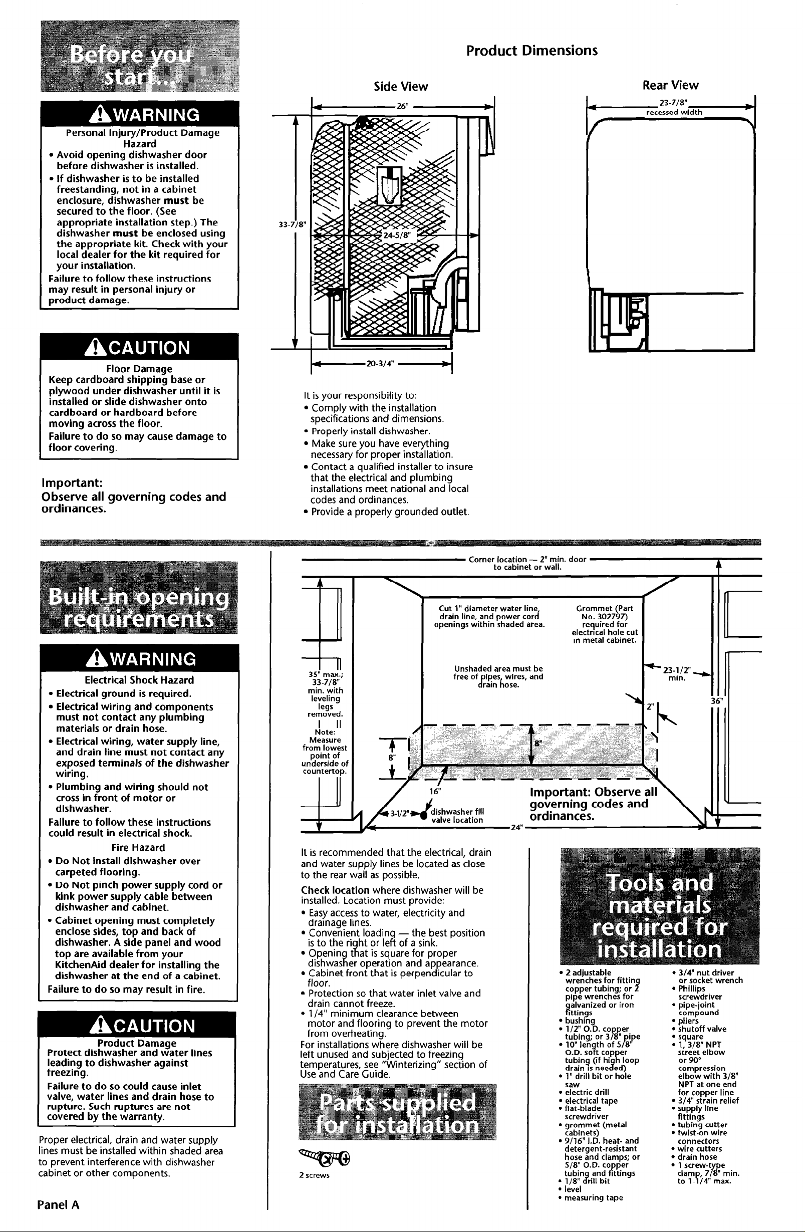
Product Dimensions
Personal Injury/Product Damage
Hazard
l Avoid opening dishwasher door
before dishwasher is installed.
l If dishwasher is to be installed
freestanding, not in a cabinet
enclosure, dishwasher must be
secured to the floor. (See
appropriate installation step.) The
dishwasher must be enclosed using
the appropriate kit. Check with your
local dealer for the kit required for
your installation.
Failure to follow these instructions
may result in personal injury or
product damaqe.
Floor Damage
Keep cardboard shipping base or
plywood under dishwasher until it is
installed or slide dishwasher onto
cardboard or hardboard before
moving across the floor.
Failure to do so may cause damage to
floor covering.
Important:
Observe all governing codes and
ordinances.
Side View
d- 26”
- 20-314”
It is your responsibility to:
l Comply with the installation
specifications and dimensions.
l Properly install dishwasher.
. Make sure you have everything
necessary for proper installation.
l Contact a qualified installer to insure
that the electrical and plumbing
installations meet national and local
codes and ordinances.
l Provide a properly grounded outlet.
Rear View
Electrical Shock Hazard
l Electrical ground is required.
l Electrical wiring and components
must not contact any plumbing
materials or drain hose.
l Electrical wiring, water supply line,
and drain line must not contact any
exposed terminals of the dishwasher
wiring.
l Plumbing and wiring should not
cross in front of motor or
dishwasher.
Failure to follow these instructions
could result in electrical shock.
Fire Hazard
l Do Not install dishwasher over
carpeted flooring.
l Do Not pinch power supply cord or
kink power supply cable between
dishwasher and cabinet.
l Cabinet opening must completely
enclose sides, top and back of
dishwasher. A side panel and wood
top are available from your
KitchenAid dealer for installing the
dishwasher at the end of a cabinet.
Failure to do so may result in fire.
Product Damage
Protect dishwasher and water lines
leading to dishwasher against
freezing.
Failure to do so could cause inlet
valve, water lines and drain hose to
rupture. Such ruptures are not
covered by the warranty.
Proper electrical, drain and water supply
lines must be installed within shaded area
to prevent interference with dishwasher
cabinet or other components.
Panel A
Corner location - 2” min. door
Cut 1” diameter water line
drain line, and power cord
openings within shaded area.
3;;-7,:.;
0
min. with
leveling
legs
removed.
h!ote:ll
Measure
from lowest
point of
underside of
countertop.
TI
8” 1
Unshaded area must be
free of$ipFh,“;es, and
dishwasher fill
valve location
It is recommended that the electrical, drain
and water supply lines be located as close
to the rear wall as possible.
Check location where dishwasher will be
installed. Location must provide:
l Easy access to water, electricity and
drainage lines.
. Convenient loadin
is to the ri
l Openin
dishwas
l Cabinet front that is perpen icular to
ht or le
#
t
at is square for proper
z
er operation and ap
-the best position
of a sink.
8
earance.
8
floor.
l Protection so that water inlet valve and
drain cannot freeze.
l l/4” minimum clearance between
motor and flooring to prevent the motor
from overheating.
For installations where dishwasher will be
left unused and subjected to freezing
temperatures, see “Winterizing” section of
Use and Care Guide.
2 screws
to cabinet or wall.
Important: Observe all
governing codes and
ordinances.
Grommet (Part
No. 302797)
required for
electrical hole cut
in metal cabinet.
l
2 adjustable
wrenches for fittin
copper tubing; or 9
pipe wrenches for
c$;gn:‘zed or iron
l
bushing
l
1” drill bit or hole
saw
l
electric drill
l
electrical tape
l
flat-blade
screwdriver
l
grommet (metal
cabinets)
l
g/16” I.D. heat- and
detergent-resistant
hose and clamps; or
l
level
l
measuring tape
- 23-112”
min. v
l
314” nut driver
or socket wrench
l
Phillips
screwdriver
l
pipe-joint
compound
l
pliers
l
shutoff valve
: ‘1’;T; NPT
sireet elbow
or 90”
compression
elbow with 318”
NPT at one end
for copper line
l
3/4” strain relief
l
supply line
fittings
l
tubing cutter
l
twist-on wire
connectors
l
wire cutters
l
drain hose
16”
After dishwasher is installed in
ing, remove terminal box cover.
Install conduit connector to box.
Insert power cable through conduit
Product Damage
l Heavy duty door springs must be
used with custom panels that weigh
more than 4 pounds. Heavy duty
door springs are attached to the
right mounting bracket located
behind the toe panel or can be
ordered from your dealer or
authorized parts distributor. Order
Door Spring Kit, Part Number
9741247.
l Maximum door panel weight is 10
pounds.
Failure to follow these instructions
could cause product damage.
L
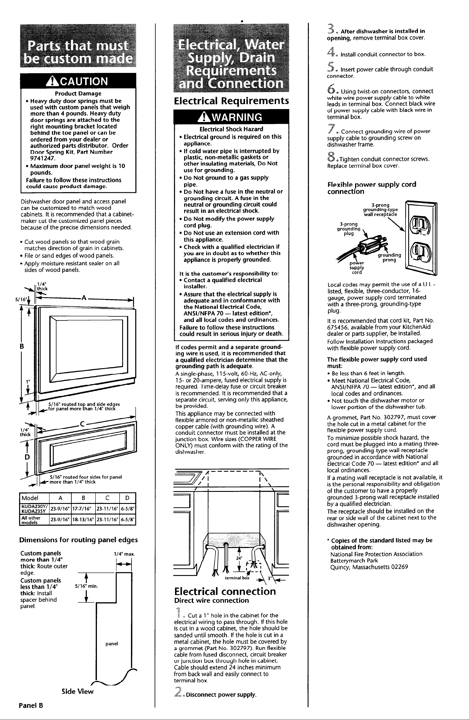
Dishwasher door panel and access panel
can be customized to match wood
cabinets. It is recommended that a cabinetmaker cut the customized panel pieces
because of the precise dimensions needed.
l Cut wood panels so that wood grain
matches direction of grain in cabinets.
l File or sand edges of wood panels.
l Apply moisture-resistant sealer on all
sides of wood panels.
S/16” routed four sides for panel
more than l/4” thick
Model
E;;;;:;;’ 23-9116” 17-7116” 23-l l/16” 6-518”
A
23-9116” 18-13/16” 23-11116” 6-5/W
B
C D
Electrical Requirements
Electrical Shock Hazard
l Electrical ground is required on this
appliance.
l If cold water pipe is interrupted by
plastic, non-metallic gaskets or
other insulating materials, Do Not
use for grounding.
l Do Not ground to a gas supply
pipe.
l Do Not have a fuse in the neutral or
grounding circuit. A fuse in the
neutral or grounding circuit could
result in an electrical shock.
l Do Not modify the power supply
cord plug.
l Do Not use an extension cord with
this appliance.
l Check with a qualified electrician if
you are in doubt as to whether this
appliance is properly grounded.
It is the customer’s responsibility to:
l Contact a qualified electrical
installer.
l Assure that the electrical supply is
adequate and in conformance with
the National Electrical Code,
ANWNFPA 70 - latest edition*,
and all local codes and ordinances.
Failure to follow these instructions
could result in serious injury or death.
If codes permit and a separate ground-
ing wire is used, it is recommended that
a qualified electrician determine that the
grounding path is adequate.
A single-phase, 11 j-volt, 60-Hz, AC-only,
15 or 20-ampere, fused electrical supply is
required. Time-delay fuse or circuit breaker
is recommended. It is recommended that a
separate circuit, serving only this appliance,
be provided.
This appliance may be connected with
flexible armored or non-metallic sheathed
copper cable (with grounding wire). A
conduit connector must be installed at the
junction box. Wire sizes (COPPER WIRE
ONLY) must conform with the rating of the
dishwasher.
- A
A.’ I
7
------l\
! ‘.
Using twist-on connectors, connect
power supply cable to white
leads in terminal box. Connect black wire
of power supply cable with black wire in
terminal box.
gr Connect grounding wire of power
supply cable to grounding screw on
dishwasher frame.
*Tighten conduit connector screws.
Replace terminal box cover.
Flexible power supply cord
connection
3-prong
grounding-type
wall receptacle
3-prong
grounding ,
Local codes may permit the use of a U.L.-
listed, flexible, three-conductor, 16gauge, power supply cord terminated
with a three-prong, grounding-type
plug.
It is recommended that cord kit, Part No.
675456, available from your KitchenAid
dealer or parts supplier, be installed.
Follow Installation Instructions packaged
with flexible power supply cord.
The flexible power supply cord used
must:
l Be less than 6 feet in length.
l Meet National Electrical Code,
ANSVNFPA 70 - latest edition*, and all
local codes and ordinances.
l Not touch the dishwasher motor or
lower portion of the dishwasher tub.
A grommet, Part No. 302797, must cover
the hole cut in a metal cabinet for the
flexible power supply cord.
To minimize possible shock hazard, the
cord must be plugged into a mating threeprong, grounding-type wall receptacle
grounded in accordance with National
Electrical Code 70 - latest edition* and all
local ordinances.
If a mating wall receptacle is not available, it
is the personal responsibility and obligation
of the customer to have a properly
grounded 3-prong wall receptacle installed
by a qualified electrician.
The receptacle should be installed on the
rear or side wall of the cabinet next to the
dishwasher opening.
Dimensions for routing panel edges
Custom panels
more than l/4”
thick: Route outer
edge.
Custom panels
less than l/4”
thick: lnstajl
spacer behind
panel.
+
5/16” min.
l/4” max.
panel
Side View
Panel B
* Copies of the standard listed may be
obtained from:
National Fire Protection Association
Batterymarch Park
Quincy, Massachusetts 02269
Electrical connection
Direct wire connection
.q
*
? %. Cut a 1” hole in the cabinet for the
electrical wiring to pass through. If this hole
is cut in a wood cabinet, the hole should be
sanded until smooth. If the hole is cut in a
metal cabinet, the hole must be covered by
a grommet (Part No. 302797). Run flexible
cable from fused disconnect, circuit breaker
or junction box through hole in cabinet.
.
Cable should extend 24 inches minimum
from back wall and easily connect to
terminal box.
q
8 Disconnect power supply.

Water requirements
Product Damage
l All solder connections must be made
before the water line is connected
to the dishwasher to prevent
damage to the inlet valve.
l Do Not solder within 6 inches of the
inlet valve. The plastic part of the
water inlet valve could be damaged.
Failure to follow these instructions
may result in product damaae.
Hot water line to dishwasher must provide
20-l 20 psi water pressure. For best results,
the hot water heater should be set to
deliver 120°F minimum temperature water
(except as noted in your Use and Care
Guide).
Use l/2” O.D. copper tubing or 3/8”
galvanized pipe inlet line. Dishwasher inlet
valve has 3/8” internal pipe thread.
Water line connection
+ Disconnect electrical supply.
e Rough in water line through the 1”
hole in cabinet rear wall or floor to
dishwasher cabinet opening.
O.D. copper tubing to form a loop 20”
above the floor. Make sure there are no
kinks in hose or copper tubing.
NOTE: An air gap must be used in the high
drain loop if the drain line is connected to
the house plumbing at a point lower than
20” above the floor.
If connection to an air gap is required, air
gap kits are available from local plumbing
supply sources.
l Install air gap according to kit
instructions.
l Entry must be above trap and at least
20” above the floor.
l Remove disposer knockout or plug
before connecting drain line.
Note: Most disposers have 7/8” connectors.
Connectors that adapt from the drain line
to disposer are available from local
plumbing supply sources.
Drain connection
Important:
Remove the disposer knockout plug
before connecting the drain hose.
%
! &“Attach drain to waste tee or waste
disposer. See “Recommended Methods”
and “Alternate Methods”.
= Rough in drain line to cabinet opening
through 1” hole in rear wall or floor.
With dishwasher in kitchen.
Electrical Shock Hazard
l Disconnect electrical power at the
fuse box or circuit breaker box
before installing dishwasher.
l Make sure that water supply line,
drain hose and wiring do not touch
any exposed terminals of the
dishwasher wiring.
Failure to do so could result in serious
injury or death.
Floor Damage
Keep shipping base under dishwasher
or slide dishwasher onto cardboard
or hardboard before moving it across
the floor.
Failure to do so may cause damage to
floor covering.
B Install a shutoff valve
in the water line where it
can be easily used.
,T,
&
B Flush water line into a bucket to get rid
ny particles that may clog the inlet
valve. Turn shutoff valve to “OFF” position.
*Check that there are no sharp bends or
kinks in the water line that may restrict
water flow.
Drain requirements
Product Damage
l The drain line connection to the
house plumbing must be a
minimum of 20” above the floor. A
lower drain connection may result
in siphoning.
l If drain line is routed to a
connection point less than 20”
above the floor, the drain line must
form a loop 20” above the floor.
l Do Not kink hose and copper
tubing.
l Do Not use a drain line or fittings
that are less than l/2” I.D.
Failure to follow these instructions
could result in poor drainage or
damage to the product.
Recommended methods:
Connect air gap to a waste tee or waste
disposer using a rubber connector.
Cut hose
waste te- y
20” ‘min.
clearance
to floor
Waste Tee Connection
’ be above
trap.
connector
to fit.
?ut hose
connector
to fit.
ti
screw-
!k
We
clamps
b Remove the 2 screws below the access
I
panel. Pull bottom of panel out and lift up
and away from dishwasher. Set access panel
aside on a protective covering.
e Measure height of
cabinet opening from
underside of countertop
to floor. Adjust
dishwasher leveling legs
to fit opening height.
The drain hose should be 9/l 6” minimum
I.D. flexible hose or 5/8” O.D. copper
tubing. A minimum of 22” flexible drain
hose, or a 12” length of copper drain line
with a 12” length of flexible hose, is
needed. Flexible hose must be resistant to
heat and detergent. Do Not use a drain or
fittings less than l/2” I.D. Flexible hose is
available through your local plumbing,
hardware or automotive supply stores.
If drain line is copper, clamp a 12” length
of 9/l 6” I.D. flexible, heat- and detergentresistant hose to the end of the copper
drain line to connect to dishwasher valve.
disposer
Entry Aust be
above trap.
. .
Waste Disposer Connection
Alternate methods:
If local plumbing codes permit, dishwasher
drain line may be connected directly to
waste tee or waste disposer. Do Not cut
hose connector to fit when connecting
directly to a disposer.
waste tee -D
A
7t7FF. ,,,.---
20”.min.
clearance
to floor
‘:g;:g’I I I
$
-7
P# I
Direct Connection to Waste Tee
Cut drain
I, hnre
connector
I screP fit’
Y clamp
DO NOT cut
Drain hose, water inlet line
and electrical supply line
routed through this area.
c Place drain hose on left side of cabinet
opening, between motor and frame. Check
that rear cross channel does not contact
drain, electrical, or water lines when
dishwasher will be installed in its final
location.
Do Not remove cross channel.
7
a>valve area
If drain line is routed to a connection
point less than 20” above floor, use 5/8”
Panel C
Direct Connection to Waste Disposer

B) Latch dishwasher door shut. Grasp
dishwasher door frame and slide dishwasher
off of shipping base or cardboard and into
cabinet opening. Do Not push on
dishwasher door panels or console. Center
dishwasher in opening. Check that front
leveling legs are firmly against floor.
@Align dishwasher door with cabinet
front - not doors.
+ Place a level
against interior
flange in the
positions shown
above. Level
dishwasher front to
back and side to
side by adjusting leveling legs.
Door and
racks not
shown for
clarity.
Door and
racks not
shown for
clarity.
n
S Open dishwasher door and remove
bottom rack. Remove all shipping materials,
including foam shipping pieces from upper
corners of door. Do Not remove the white
plastic plug buttons from the side of the
door or the plastic bumpers from the front
corners of the lower rack. Place a
newspaper or large sheet of paper over
bottom of dishwasher to protect pump area
when securing dishwasher to countertop.
Personal Injury/Product Damage
Hazard
l The dishwasher must be secured to
the countertop to keep it from
tilting when the door is open.
l If dishwasher is to be installed
freestanding, not in a cabinet
enclosure, dishwasher must be
secured to the floor. (See
appropriate installation step.) The
dishwasher must be enclosed using
the appropriate kit. Check with your
local dealer for the kit required for
your installation.
l Do Not drop screws in dishwasher
tub. If screws should fall into pump,
pump and motor damage may
occur.
Failure to follow these instructions
may result in personal injury or
product damage.
Numbers
correspond to
steps.
*The dishwasher must be secured to
the countertop or floor to prevent tipping
when dishwasher door is opened.
Countertop attachment:
Disconnect brackets located at top corners
of flange. Reattach brackets with bracket
end facing away from dishwasher. Using a
l/8” drill bit, drill 3/4” deep starter holes
through bracket holes into underside of
countertop. Do Not exceed 3/4” depth.
Attach brackets to underside of countertop
using two screws from parts bag. Make
sure screw heads do not interfere with
door.
equally spaced,. ,
Open dishwasher door approximately 3”
and check for equal spacing between inner
door and tub sides. If space is unequal,
loosen screws fastening dishwasher to
countertop and shift tub. Check that
dishwasher is level and reattach screws.
inlet valved
p
street elbow
NPT
o Water inlet valve has 3/8” internal pipe
thread.
If galvanized pipe is used, connect a 3/8”
NPT street elbow to water inlet valve using
pipe-joint compound.
If 90” compression elbow is used, connect
3/8” end to water inlet valve. Use pipe-joint
compound. Do Not use pipe-joint
compound on the compression end.
Tighten connection.
Use pipe-joint compound to connect
water line to street elbow. Do Not use
pipe-joint compound to connect water
line to compression elbow.
Tighten connection.
Panel D
Floor attachment:
leveling leg
Attach dishwasher to floor using l/4” lag
bolts through holes in each side of
dishwasher frame, being careful to keep
dishwasher level.
Place screw-type clamp over
straigh: end of connector drain hose.
Attach drain hose to connector drain hose
with screw-type clamp. Check that drain
hose and connector drain hose are not
twisted or kinked and that the connection is
secure.

Personal Injury/Property Damage
Hazard
Wear gloves and handle metal edges
of panels carefully.
Cut metal edges are sharp and may
cause personal injury or damage to
other materials.
S Remove the newspaper protecting
the pump. If color of door panel is to be
changed or custom panels installed, change
panels now. See Use and Care Guide for
instructions.
*Check dishwasher door for proper
operation. Door should close easily without
slamming and should not fall open or shut
from its own weight.
If door closes from an open position,
adjust door spring brackets upward to a
different hole.
If door falls open too quickly, move spring
brackets downward.
If custom door panels weigh more than
4 pounds, install heavy-duty door springs.
L Make electrical connection. See
“Electrical connection,” Panel B. CHECK
ELECTRICAL REQUIREMENTS. BE SURE
YOU HAVE CORRECT ELECTRICAL SUPPLY
AND RECOMMENDED GROUNDING
METHOD. Check that all parts have been
installed and no steps were skipped. Check
that no screws have fallen into the tub.
Reinstall rack in dishwasher. Turn on
electrical and water supplies.
If dishwasher does not operate...
Check that:
l the circuit breaker is not tripped or the
house fuse blown.
l dishwasher door is closed tightly and
latched securely.
l dishwasher rack is in place.
l dishwasher cycle has been set correctly.
l water has been turned on.
l electrical power has not been
interrupted.
Note: If the motor has stopped because of
overload, it will automatically reset itself
within a few minutes. A detailed
troubleshooting checklist is provided in the
Use and Care Guide.
If you need assistance...
The KitchenAid Consumer Assistance Center
will answer any questions about operating
or maintaining your dishwasher not covered
in the Installation Instructions. The
KitchenAid Consumer Assistance Center is
open 24 hours a day, 7 days a week. Just
dial 1-800-422-l 230 - the call is free.
When you call, you will need the
dishwasher model number and serial
number. Both numbers can be found on
the serial/rating plate located on tub
behind door.
S Start dishwasher on the NORMAL
wash cycle. Allow it to run 5 minutes. Check
that there are no leaks. Open dishwasher
door to stop cycle. Close dishwasher door
and manually advance timer to final drain.
When dishwasher stops, check that it has
drained.
9 Install top of access panel into
channel and rotate panel towards dish-
washer. Reattach the access panel with two
screws. Check that the opening at the
bottom of access panel is clear so air can
circulate to cool motor.
If you need service...
In the event that your KitchenAid appliance
should need service, call the dealer from
whom you purchased the appliance or a
KitchenAid-authorized service company. A
KitchenAid-authorized service company is
listed in the Yellow Pages of your telephone
directory under “Appliances - Household
-
Major - Service or Repair”. You can also
obtain the service company’s name
telephone number by dialing, free, within
the continental United States, the
KitchenAid Consumer Assistance Center
telephone number, 1-800-422-l 230. A
special operator will tell you the name and
number of your nearest KitchenAidauthorized service company.
Maintain the quality built into your
KitchenAid appliance - call a KitchenAidauthorized service company.
and
Panel E

Printed on recycled paper.
10% post consumer waste/
50% recovered materials.
Part No. 9741514 Rev. D
0 1993 KitchenAid.
8 Registered Trademark of KitchenAid.
HOME APPLIANCES
Prepared by KitchenAid, St. Joseph, Michigan 49085
Printed in U.S.A.
 Loading...