

Page 1

D
P585 DMR Two Way Radio
User Guide
DP585
MR Two Way Radio
D
W
e are very grateful for your purchasing Kirisun brand two-way radio produced by Kirisun
Communications Co., Ltd.
We believe Kirisun two-way radio, which always incorporates the latest technology, can
bring gr eat c onvenience t o your l ife and w ork. We al so bel ieve t hat t he qual ity and
function of Kirisun two-way radio can meet your demands for reliable communication.
III
Us
er Guide
Page 2

DP585 DMR Two Way Radio User Guide
Notice
◆ Please carefully read this i nstruction manual be fore using the product for your easy operation. We will
consider that you have read this manual when you use the product.
◆ Please carefully keep the manual for future reference.
◆ In order to protect your legal rights from infringement, please carefully fill in the warranty card and claim
valid receipt.
◆Kirisun and our authorized partners own the intellectual property of all the parts of this product (including
accessories). Any design an d m aterials m ay not b e modified, c opied, extracted o r translated w ithout
authorization of Kirisun or its authorized parities.
◆This product may involve update or modification in future, and Kirisun owns the right to change the
specifications of software and hardware described in this manual without further notice. Specifications and
information contained in this manual are for reference only.
◆ All the contents are carefully proofread, but mistake may be inevitable. The rights of final explanation are
preserved by Kirisun.
Page 3

DP585 DMR Two Way Radio User Guide
Safety Precaution
◆The radio can only b e repaired or m aintained by professional technicians. The user must not
disassemble the radio at liberty.
◆In order to avoid problems caused by electromagnetic interference or electromagnetic incompatibility,
please turn off the radio in the place such as hospital, plane and other health care centers where there is a
sign such as “Turn off Your Radio”.
◆In the car with a ir bags, please do not keep your radio at the p lace within possible r each of t he a ir bag
spread.
◆Please turn off your radio before entering flammable or explosive environment.
◆ Do not change or charge the battery in flammable or explosive environment.
◆ Please turn off your radio when getting closer to the blast zone or thunder zone.
◆Do not use any radio with damaged antenna, which may cause slight burning to the skin in contact.
◆Please make sure that the antenna is properly attached when using the radio.
◆Please keep the radio vertical when it is transmitting, and also keep the microphone 5 cm away from your
mouth.
◆Please make sure that the antenna is 2.5cm away from your body when the radio is transmitting.
2
Page 4

DP585 DMR Two Way Radio User Guide
Battery
◆If the conductive substance on human body makes contact with the exposed battery terminal,
it may damage your belongings, and/or do harm, such as burning, to human body. Conductive
material includes jewelry, keys or bead-like necklace. They can form a l oop (it causes short
circuit) with battery and c ause skin burn after t he rapid temperature rise. Be c autious when
managing a charged battery, especially when you put it in the pocket, wallet or container with
metallic objects. To decrease the risk of being harmed, the battery cannot be e xposed in the
file, disassembled or squeeze.
◆ The hi ghest envi ronment t emperature ar ound t he pow er s upply devi ce or vol tage
transformer must not be higher than 40°C (104°F).
◆ Please turn off the radio attached with battery when charging. Using radio during charging
will affect its charging process.
◆ Please do not put t he r adio and bat tery i nto t he c harger w hen t hey ar e not i n nee d of
charging, and constant charging will shorten the battery life. Do not use the charger as a store
to radio.
◆ To achieve optimal performance, we recommend changing battery after one-year use.
Page 5
DP585 DMR Two Way Radio User Guide
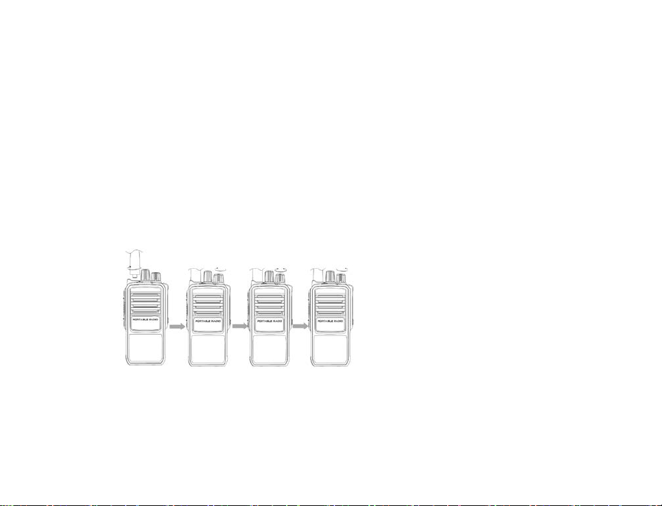
Brief Introduction
1.Attaching the antenna: put the antenna into the antenna interface, and rotate the antenna clockwise to fix
it.
2.Powering on: rotate the power/volume knob to power on the radio.
3.Channel Selection: rotate the channel selection knob to select channel.
4.Powering off: rotate the power/volume knob clockwise to power off the radio
Page 6

DP585 DMR Two Way Radio User Guide
Contents
1
UNPACKING AND CHECKING ...............................................................................10
2 BATTERY INFORMATION ......................................................................................10
3 ATTACHING THE ACCESSORIES .........................................................................10
4 INTRODUCTION......................................................................................................18
5 PROGRAMMABLE KEYS ........................................................................................20
6 BASIC OPERATION ................................................................................................23
7 FEATURES AND OPERATION ...............................................................................26
8 TROUBLESHOOTING .............................................................................................30
9 MAJOR TECHNICAL SPECIFICATION ..................................................................31
10 RESTRICTIONS ARE VALID FOR THE EUROPEAN COUNTRY .........................37
11 CAUTION .................................................................................................................38
12 FCC STATEMENT ...................................................................................................39
13 IC STATEMENT .......................................................................................................40
6
Page 7
DP585 DMR Two Way Radio User Guide
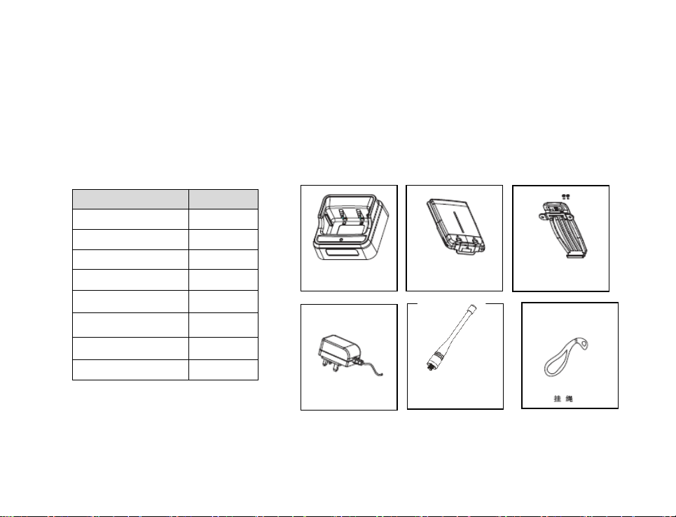
Material
Quantity
Radio
1
Charger
1
Power Adaptor
1
Battery
1
Belt Clip
1
Antenna
1
Strip
1
User Manual
1
Charger
1 Unpacking and Checking
Please carefully open the box, and check if the accessories listed below are contained in the package. For any
missed or damaged item, please contact your local dealer for solution.
1.1 Supplied Accessories
2 Battery Information
Battery
Power Adaptor
Antenna
Belt Clip+ screw
Strip
Page 8

DP585 DMR Two Way Radio User Guide
2.1 Notice
The battery is not charged before delivery, so please charge the battery for your first use. If the battery is
not used for a long time or the battery is used up, please charge it before use. Charge/discharge for twice
or three times alternately to achieve its optimal performance. For low battery, please charge it or replace it.
Note:
◆Do not cause any short circuit on the battery or throw the battery into fire.
◆When attaching t he bat tery t o t he r adio f or c harging, pl ease m ake s ure t he r adio i s pow ered of f t o
guarantee it can be fully charged.
◆Do not leave the radio or battery on the charger after it is fully charged. Unnecessary constant charging
will shorten the battery life.
◆Do not put the fully-charged battery back to the charger for re-charging, or it may shorten the battery life.
◆Please try to keep the battery in an indoor environment at around 25℃. The battery may get easily
spoiled after being kept in the environment below -10℃ for a long time.
◆In temperature higher than 35℃ or below -10℃, the dischargeable power of the battery may decrease
due to the physical property of lithium battery.
8
Page 9
DP585 DMR Two Way Radio User Guide
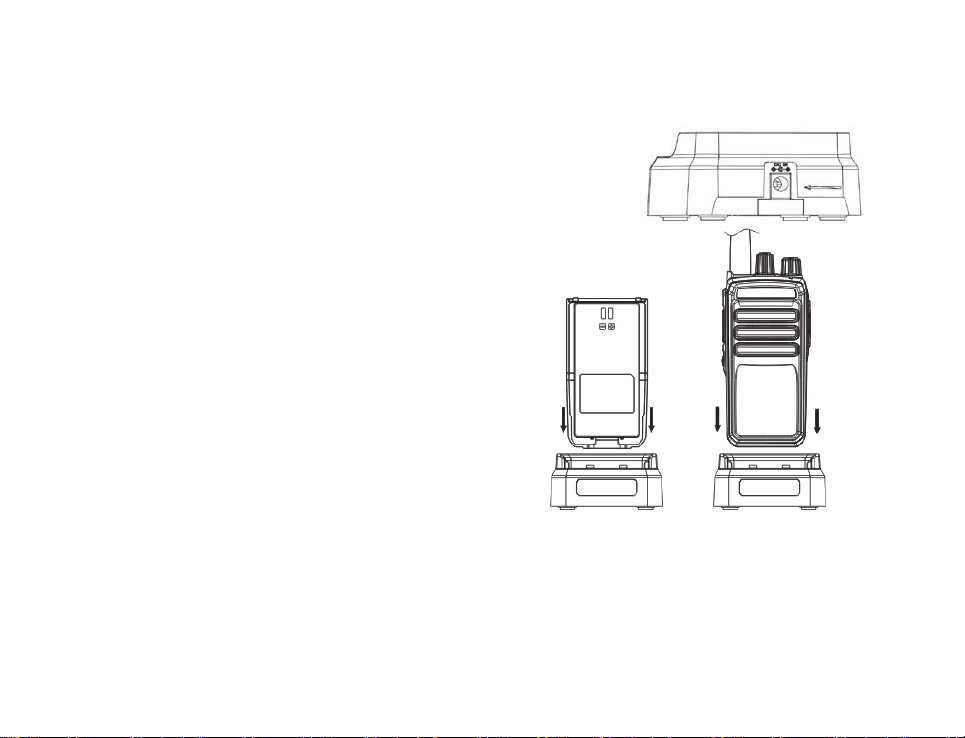
2.2 Battery Charging
(1) Plug the power adaptor in the proper socket of AC power.
(2) Plug the cable of the power adaptor at the back of the socket, and
the green indicator glows.
(3) Plug the battery or radio in the charger.
(4) Make sure that the battery is in proper contact with the
charger terminal, and the red indicator glows.
(5) After the ba ttery i s charged f or 6 hours, the r ed l ight
goes out, indicating that the battery is fully charged.
(6) When the green indicator glows, keep the battery on the
charger f or 1 -2 hour s bef ore t aking i t ou t so a s t o
achieve the optimal performance.
(7) Take out the pow er adapt or f rom t he socket o f A C
power output.
Note:
The battery is not charged before delivery from the factory, so please charge the battery before your first
use.
Page 10
DP585 DMR Two Way Radio User Guide
Kirisun KB-75A lithium-ion can be used for this radio.
If the battery which is stored for over 2 months or a new battery is charged for the first time, it should be
charged r epeatedly t o gain full battery capacity. The battery s hould be at least charged once every
three months.
When the ba ttery is f ully charged or the bat tery power i s above the l evel of low pow er al ert, do not
charge the battery, or it may affect the battery life and performance. Please take out the battery from
the charger after it is fully charged.
When the radio enters the state of low voltage alarm, please charge the battery before using it and do
not force to power on the radio in case that the battery life and performance is impaired.
There is protection circuit inside KB-D415 lithium battery. The power supply will be cut off in state of low
power, and when you charge it in the charger, the indicator will glow after 1-5 minutes.
3 Attaching the Accessories
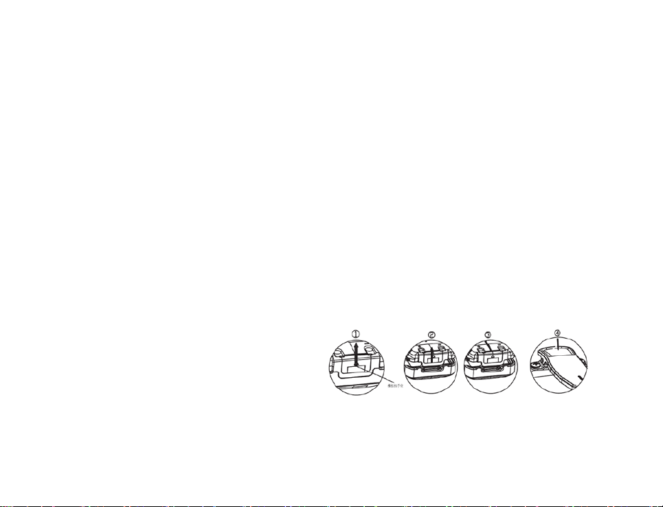
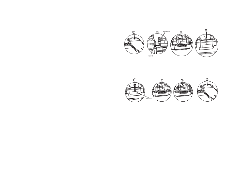
3.1 Attaching/Detaching the Battery
◆Attaching the Battery
(1) Slightly press the top of the belt clip as shown in ①;
10
Page 11
DP585 DMR Two Way Radio User Guide
(2) Align the battery with the battery installation base
at the back and insert the battery as shown in ②.
(3) Slide t he battery along the direction as shown in
③ until the battery is fit into the right position.
(4) Slightly press the battery top as shown in ④ until
the battery is locked by the latch.
◆Detaching the battery
(1) For detaching the battery, please first turn off the
radio.
(2) Slide the bat tery l atch al ong the di rection as
shown in ① to bounce the battery as shown in
②.
(3) Slide to take out the battery along the direction as shown in ③. If there is belt clip, slightly press the belt
clip top as shown in ④ and slide the battery along the direction as shown in ③ to take out the battery.
Note:
Do not throw the battery terminals with short circuit or battery into fire.
Do not remove the battery case without permission.
Page 12
DP585 DMR Two Way Radio User Guide
3.2 Attaching/Detaching the Antenna
For at taching the antenna, put the antenna’s end w ith screw t hread into the
antenna port.
Turn the antenna clockwise until it is fixed.
For detaching the antenna, turn it counter-clockwise.
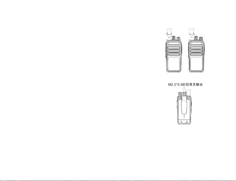
3.3 Attaching/Detaching the Belt Clip
Align t he two s crews on t he belt clip with t he screw hol es at the back of the
radio.
Use two 2.5x6.5 machine screws.
When detaching, loosen the two screws on the belt clip and remove the belt clip.
12
Page 13
DP585 DMR Two Way Radio User Guide
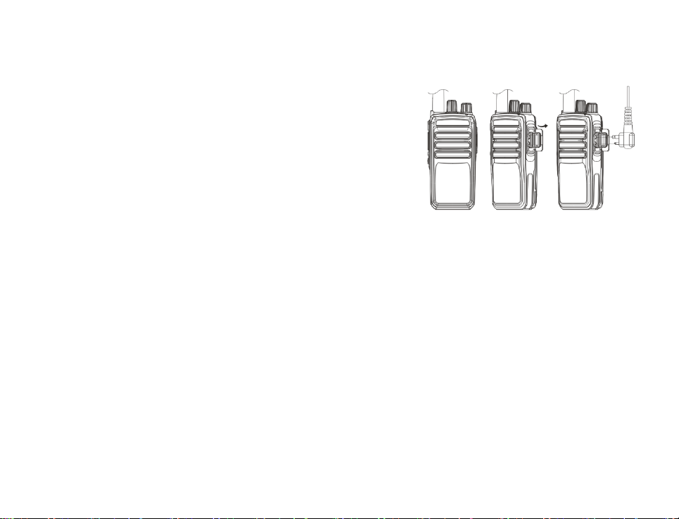
3.4 Attaching the Microphone
Open t he ear phone c over pl ate on t he r ight and connect the
earphone cable to the port.
Page 14

DP585 DMR Two Way Radio User Guide
4 Introduction
Page 15

DP585 DMR Two Way Radio User Guide
Power/Volume Knob
turning of f the r adio, t urn i t
adjust the volume.
LED Indicator
power shortage.
Side key (programmable key)
This key c an be s et w ith di fferent
No. Part Name No. Part Name
Turn it clockwise to turn on the radio. For
Antenna
1
7
counter-clockwise until a click is heard.
When the radio is on, rotate the knob to
PTT key
2
Press this key to initiate a call and talk
3
features by dealer. Please refer to “5
Programmable Keys” for further details
8
9
2
Red indicator means the radio is
transmitting, green means receiving and
when the red indicator flashes, it means
Microphone
Voice input
Page 16

DP585 DMR Two Way Radio User Guide
External port
external speaker and microphone
Channel Knob
Rotate the knob to select channel 1-16.
4
Alarm Key 10
Speaker
5
Voice output。
11 Belt Clip
Open the cover plate and connect the
6
5 Programmable Keys
5.1 Programmable Keys
To suit the operation habits of customer, programmable keys (side keys) are available and can be set
by dealer as shortcut key.
Note:
Short Press: press and release quickly.
Long Press: press and hold for a while (press duration can be set by programming software)
No. Programmable Application
12 Battery Latch
Page 17

DP585 DMR Two Way Radio User Guide
Feature
If the current anal ogue c hannel has CTCSS, press this key and
Starts the emergency feature. Used for seeking help in
Enable/Disable squelch feature. U sed f or r eceiving t he w eak
1 None No feature
2 High/Low Power Switch to high and low power
3 Monitor
4 Emergency
5 Emergency Exit Exits the emergency state.
6 Squelch on/off
7 Squelch Level Adjusts the signal strength required when receiving.
switch to carrier squelch mode to cancel CTCSS; press it again to
go back to the original state.
emergency.
signals on the analogue channel.
4
Page 18

DP585 DMR Two Way Radio User Guide
Enable/Disable s can feature and listens t o t he c ommunication
Press t his k ey to switch a mong different z ones. The z ones ar e
Repeater/Talk
8 Scan
9 Alert Tone on/off Enable/disable all the alert tones.
10 Zone Selection
11
12 Nuisance Delete Deletes the channel which is useless from the scan list.
around
activities on other channels.
programmed by programming software.
Enable/disable Repeater feature.
5.2 LED Indication
State Operation
Glows red Transmitting
Page 19

DP585 DMR Two Way Radio User Guide
Flashes green
Channels are being scanned
Flashes green
The pr ogramming software i s w riting the par ameters w hich i s a vailable f or
Glows green Receiving
Flashes red Low battery
Flashes orange Digital call hang time and it will exit when the hang time is up
Glows orange Blank channel which is not available. Switch to other channel to exit.
Flashes red quickly The programming software is reading the parameters available for configuration
quickly
configuration into the radio.
6 Basic Operation
6
Page 20

DP585 DMR Two Way Radio User Guide
6.1 Powering on/off the Radio
When the radio is off, rotate the power/volume knob clockwise until a click is heard to power on the radio.
When the radio is on, rotate the power/volume knob counter-clockwise until a click is heard to turn off the
radio.
6.2 Selecting the Channel
When the radio is on, rotate the channel selector knob to select channels.
6.3 Adjusting the Volume
When t he r adio i s on, r otate t he pow er/volume knob clockwise t o increase the volume and
counter-clockwise to decrease the volume.
6.4 Initiating a Call
Press PTT button to initiate a call to the default contact on the current channel when it is digital channel.
The default contact on the current channel can be programmed by dealer.
Page 21

DP585 DMR Two Way Radio User Guide
6.5 Receiving
When the radio receives RF signal on the current channel and reaches squelch start level, the green LED
glows to indicate that carrier is received.
When the current channel is digital channel and when it received private call, group call or all call, the
radio will output the voice from the channel.
When the channel is analogue channel and w hen it received analogue signals with CTCSS matching
the one on this channel (or there is no CTCSS set on the channel), the radio will output voice form the
channel.
6.6 Replying to the Call
When the current channel is digital channel and after a call is received, press PTT button within the call
hang time to reply. If the call hang time is up, you need to initiate a call to reply. The call hang time can
be set by dealer.
When the current channel is analogue channel and after a call is received, press PTT button within the call
hang time and speak to the microphone to reply.
8
Page 22

DP585 DMR Two Way Radio User Guide
7 Features and Operation
7.1 TOT (time-out-timer)
TOT prevents the user from occupying the channel for too long. If the continuous transmission exceeds
the dur ation set by deal er, t he r adio w ill stop t ransmitting and sound al arm. F or s topping al arm,
release P TT bu tton. F or t ransmission agai n, pl ease pr ess P TT bu tton after a certain time i nterval
(interval set by dealer).
If the dealer set pre-alarm feature, pre-alarm will sound before TOT time is up.
7.2 Channel Scan
Channel scan searches channels with signals. When the channel scanned has signals, the radio will
stay on this channel for communication. Scan method is carrier control scan.
By pressing the Scan shortcut key, t he r adio can scan the s can list r elated to t he current channel.
When the radio is in scan state, press the Scan shortcut key again to stop the scan.
Page 23

DP585 DMR Two Way Radio User Guide
7.3 Scan the Reply Message
When the r adio is scanning, press PTT button and the radio will transmit and talk on the predefined
channel. This channel is set by dealer.
7.4 Priority Scan
When there is priority scan set in the scan list, the priority scan will be automatically enabled when the
radio starts the scan feature. The priority scan mode is cycle scan, and it scans priority channel every
time when it scans a conventional channel. For example, if there are channel 1, 2, 3, 4 in the scan list
and channel 2 is priority channel, the scan cycle will be 1->2->3->2->4->2->1.
7.5 Kill and Unkill
If t he deal er enabl es and sets Kill and U nkill, the radio is able to receive and de code the Kill/Unkill
signals from other r adios. After being killed, t he radio cannot transmit or receive any signals but
activation signal. After being activated, the radio will be back to normal state. Kill/Unkill feature is valid
on digital mode.
10
Page 24

DP585 DMR Two Way Radio User Guide
7.6 Emergency
In state of emergency, press the Emergency shortcut key to send emergency alarm.
Emergency alarm consists of two parts: alarm type and alarm mode. Alarm mode is used to specify the
contents sent to other members in emergency. You can ask your dealer to set these parameters based
on your requirements.
For exiting emergency, press again the Emergency shortcut key.
◆ Alarm Mode
Emergency Alarm: enable to send alarm and exit alarm state automatically afterwards.
Emergency Alarm + Emergency Call: after the radio sends emergency alarm, press PTT button to send
emergency call.
Emergency Alarm + Auto Background Tone: after the radio sends emergency alarm,the background tone
will be sent automatically in the way of emergency call.
◆Alarm Type
None: no alarm feature (default).
Page 25

DP585 DMR Two Way Radio User Guide
Siren Only: after the radio enters the alarm state, the siren can only sound locally and the control center
will not receive any alarm signals.
Conventional: after the radio enters alarm state, there will be light and sound alert and it can also receive
response from other members.
Secret: after t he r adio ent ers al arm state, there w ill be no l ight or s ound al ert, and i t cannot r eceive
response from other members.
Secret with Voice: after the radio enters alarm state, there will be no light or sound alert but it can receive
response from other members.
Note:
Emergency Alarm: the radio transmits non-speech signal to trigger the alarm sent from other radios.
Emergency Call: it is a call mode which is faster in occupying channel than common calls, which ensures
smooth call in emergency.
12
Page 26

DP585 DMR Two Way Radio User Guide
to pow er
A. The battery is used up –charge the battery or change to a new
Small v oice
7.7 Enabling Color Code on Digital Mode
Only when both the color code and ID matches, the speaker can be turned on to receive.
Range: 0~15 (16 groups of color codes)
8 Troubleshooting
No. Problem Cause and Solution
Failed
on
during call
battery;
B. Volume switch is faulty – repair at the specified service station;
A. speaks too far from the microphone – the ideal distance: 3-10cm;
B. wrong volume setting – turn the v olume knob clockwise to increase
the volume;
1
2
Page 27
DP585 DMR Two Way Radio User Guide
General Specification
Frequency Range
UHF : 400 – 470MHz
Modulation Type:
Analog: FM Digital: 4FSK
Channel Separation:
Analog: 12.5kHz, 20kHz, 25kHz
Rated Output Power:
High: 4W Low: 1W
3
Failed to transmit
or receive
9 Major Technical Specification
A. wrong channel parameters – reset the parameters and try again;
B. the group identity for default contact is wrong – select a right group;
C. Beyond the communication scope.
Digital: 12.5kHz
14
Page 28

DP585 DMR Two Way Radio User Guide
Bluetooth
Version:
Bluetooth 4.2 EDR+BLE
Modulation:
GFSK, π/4QPSK, 8DPSK
Operation frequency:
2402MHz~2480MHz
Channel number:
79 Channel for EDR
Channel separation:
1MHz for EDR
GPS
Modulation:
MSK
Operation frequency:
1575.42MHz
40 Channel for BLE
2MHz for BLE
Page 29
power (W)
DP585 DMR Two Way Radio User Guide
Engineering per sonnel s etting up t hose frequency r anges w hit Customer P rogramming S oftware(CSP),
the mechanism implemented in the product to avoid the end user to managing changes in the definition of
operating frequency ranges in order to avoid usage of un-allowed frequency ranges.
Country Frequency Range(MHz)
Germany(DE) 406.1-430 ,440-470 4
France (FR) 406.1-430,444.5-447, 451.5-460, 461.5-470 4
United
Kingdom (UK)
Italy(IT) 440-443,445-470 4
Greece(EL) 406.1-430 ,440-470 4
Spain(ES) 406.1-430 ,440-470 4
Ireland (IE)
410-430 ,440-470 4
410 - 430,440 - 455, 456 - 459,460 - 470
16
Max.transmit
4
Page 30

DP585 DMR Two Way Radio User Guide
406.1-430 ,440-470
406.1-430 ,440-470
406.1-430 ,440-470
406.1-430 ,440-470
406.1-430 , 450 - 470
443 - 450,446 -446.2,450 -453 ,457.575 - 463,467.575 -470
Belgium(BE)
Croatia (HR)
Cyprus (CY)
Portugal (PT)
Malta(MT)
Luxembourg (LU)
Bulgaria(BG)
Latvia (LV)
Slovenia(SI)
Czech Republic
(CZ)
Denmark(DK)
Estonia(EE)
Lithuania(LT)
440-470
406.1-430 ,440-470
410-430,440- 470
410 -430,440-470
406.1-430,440-450,456 -470
448 - 451.3 ,457.38 - 461.3 ,467.38 - 470
406.1 - 410,412.5 - 420 , 422.5-430 ,440 - 442.5,
406.1 - 410 , 413 - 418.6 ,423- 428.6 ,440 - 450 ,
4
4
4
4
4
4
4
4
4
4
4
4
4
Page 31

DP585 DMR Two Way Radio User Guide
450 - 452.9875 ,458.1125 - 462.9875 ,467.4875 - 467.5875
417 - 420,442 - 445,456 - 460, 461.3 - 470
410 -430,440-470
457.45 - 458.3,460 -470
448 - 449.5,457 - 460,467 - 470
457.5 - 458.2, 460 - 460.55,467.5 - 468.2
447.00625 - 447.29375,447.30625 - 447.70625,
Hungary(HU)
Netherlands(NL)
Austria(AT)
Poland(PL)
Romania (RO)
Slovakia(SK)
Finland(FI)
444.9 - 444.900001, 450 - 456, 457.33 - 457.330001,
408 - 410.8,415 - 420.8,425 - 429.8, 440 - 450.55,
441.025 - 451.31,455.73 - 461.31,465.73- 470
407.525 - 408.55,410.0125 - 410.8875,417.525 - 417.9,
419.15 - 419.525,419.55625 - 419.71875,420.0125 -
420.8875,426.35 - 427.5,427.525 - 427.9, 429.15 -
429.525,429.55625- 429.71875,440.0125 - 440.5875,
440.60625 - 440.89375,442.775 - 443, 443.025 - 444,
444.025 - 444.525,444.55 - 444.975,445 - 446,
4
4
4
4
4
4
4
18
Page 32

DP585 DMR Two Way Radio User Guide
452.525 - 452.975,453.0125 - 453.6625,469.725 - 469.975
457.5 - 462.5,467.5 - 470
449.025 - 449.525,449.55 - 449.975, 450.325 - 452.475,
Sweden(SE)
406.1 -430, 442 - 444,444.5875 - 452.5,
4
Page 33

DP585 DMR Two Way Radio User Guide
10 Restrictions are valid for the European country
Restrictions are valid for the following countries:
France (FR) , United Kingdom (UK) , Italy(IT) , Ireland (IE) , Portugal (PT) , Luxembourg (LU) ,
Bulgaria(BG) ,Latvia (LV),Czech Republic (CZ) ,Denmark(DK) ,Estonia(EE) ,Lithuania(LT) , Hungary(HU) ,
Netherlands(NL) ,Austria(AT) , Poland(PL) ,Romania (RO) ,Slovakia(SK) , Finland(FI) ,Sweden(SE)
20
Page 34

85 DMR Two Way Radio
DP5
12
CC STATEMENT
F
Thi
s device complies with Part 15 of the FCC Rules. Operation is subject to the following two conditions:
(1) This device may not cause harmful interference, and
(2) this device must accept any interference received, including interference that may
cause undesired operation.
NOTE 1:
This equipment has been tested and found to comply with the limits for a Class B digital device ,
pursuant to part 15 of the FCC Rules. These limits are designed to provide reasonable protection against
harmful interference in a residential installation. This equipment generates, uses and can radiate radio
frequency energy and, if not installed and used in accordance with the instructions, installed and used in
accordance with the instructions, may cause harmful interference to radio communications. However,
there is no guarantee that interference will not occur in a particular installation. If this equipment does
cause harmful interference to radio or television reception, which can be determined by turning the
equipment off and on, the user is encouraged to try to correct the interference by one or more of the
following measures:
User Guide
22
Page 35

DP585 D
- R
- Increase the separation between the equipment and receiver.
-Connect the equipment into an outlet on a circuit different from that to which the
receiver is connected.
-Consult the dealer or an experienced radio/TV technician for help.
NOTE 2: Any changes or modifications to this unit not expressly approved by the party responsible
for
Output power listed is rated conducted. This device must be restricted to work-related operations
only in an Occupational/Controlled RF exposure environment and must operate with a duty factor
not exceeding 50%. This transmitter may operate with the antenna(s) documented in this filing in
Push-to-Talk and body-worn configurations. RF exposure compliance is limited to the specific
belt-clip and accessory configurations as documented in this filing and the separation distance
between user and the device or its antenna shall be at least 2.5 cm. All qualified end-users of this
device must have the knowledge to control their exposure conditions and/or duration to comply
with occupational/controlled Exposure limit and requirements. The highest reported SAR values
for Face-held, body-worn and simultaneous transmission conditions are 2.06 W/Kg, 2.91 W/Kg
and 2.92 W/Kg respectively.
This device contains Bluetooth, BLE and Two Way Radio transmitters.
MR Two Way Radio
eorient or relocate the receiving antenna.
compliance could void the user's authority to operate the equipment.
User Guide
Page 36

85 DMR Two Way Radio
DP5
13
C STATEMENT
I
Thi
s device complies with Industry Canada license-exempt RSS standard(s): Operation is subject to the
following Two conditions:
(1) this device may not cause interference, and
(2) This device must accept any interference, including interference that may cause undesired operation
of the device.
Le present appareil est conforme aux CNR d'Industrie Canada applicables aux appareils radio exempts
de licence. L'exploitation est autorisée aux deux conditions suivantes :
(1) l'appareil ne doit pas produire de brouillage, et
(2) l'utilisateur de l'appareildoit accepter tout brouillage radioélectrique subi, même si le brouillage est
susceptible d'en compromettre le fonctionnement.
The information listed above provides the user with information needed to make him or her aware of a
RF exposure, and what to do to assure that this radio operates within the FCC exposure limits of this
radio.
User Guide
24
Page 37

- 2 -
 Loading...