

Page 1
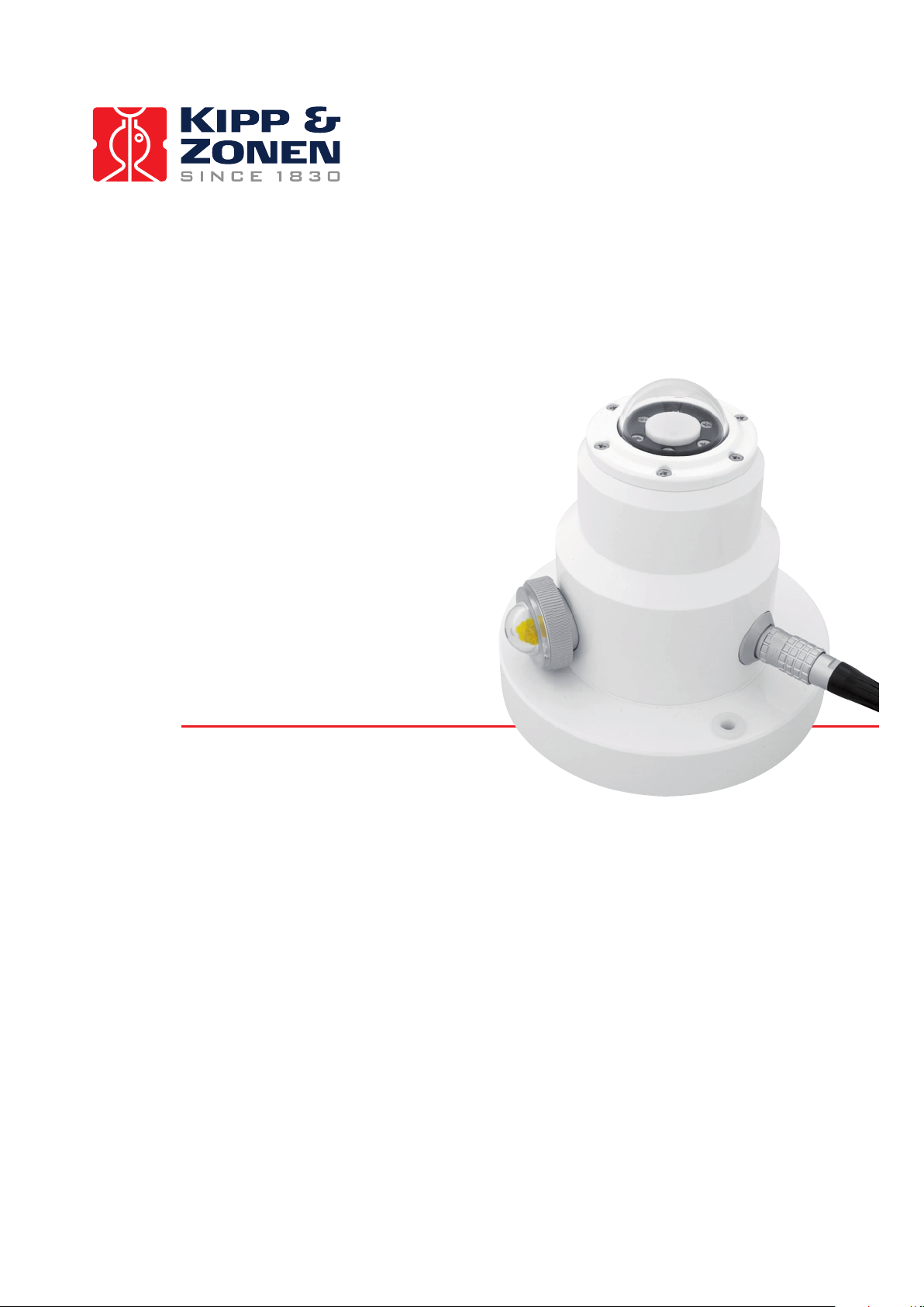
Instruction Manual
UV Radiometers
UVS series
Page 2
IMPORTANT USER INFORMATION
Reading this entire manual is recommended for full
understanding of the use of this product.
Should you have any comments on this manual we will
be pleased to receive them at:
Kipp & Zonen B.V.
Delftechpark 36
2628 XH Delft Holland
P.O. Box 507 2600 AM Delft Holland
Phone +31 (0)15 2755210
Fax +31 (0)15 2620351
Email info@kippzonen.com
Web www.kippzonen.com
Kipp & Zonen reserve the right to make changes to the
specifications without prior notice.
Kipp & Zonen guarantees that the product delivered has been
thoroughly tested to ensure that it meets its published
specifications. The warranty included in the conditions of
delivery is valid only if the product has been installed and used
according to the instructions supplied by Kipp & Zonen.
Kipp & Zonen shall in no event be liable for incidental or
consequential damages, including without limitation, lost
profits, loss of income, loss of business opportunities, loss of
use and other related exposures, however caused, arising
from the faulty and in correct use of the product.
User made modifications can affect the validity of the CE
declaration.
All rights reserved. No part of this publication may be
reproduced, stored in a retrieval system or transmitted in any
form or by any means, without permission in written form from
the company.
WARRANTY AND LIABILITY
©
COPYRIGHT
2007 KIPP & ZONEN
Manual version: 0712
2
Page 3

DECLARATION OF CONFORMITY
According to EC guideline
89/336/EEC 73/23/EEC
We Kipp & Zonen B.V.
Of Delftechpark 36
2628 XH Delft
The Netherlands
Declare under our sole responsibility that the products
Types: UVS-A-T, UVS-B-T, UVS-E-T, UVS-AB-T, UVS-AE-T
Name: UV Radiometer
To which this declaration relates is in conformity with the
following standards
Imissions EN 50082-1 Group standard
Emissions EN 50081-1 Group standard
EN 55022
Safety standard IEC 1010-1
Following the provisions of the directive
B.A.H. Dieterink
President
Kipp & Zonen B.V.
3
Page 4

TABLE OF CONTENTS
IMPORTANT USER INFORMATION 2
DECLARATION OF CONFORMITY 3
TABLE OF CONTENTS 4
1. GENERAL INFORMATION 5
1.1 INTRODUCTION 5
2 TECHNICAL DATA 7
3 INSTALLATION 8
3.1 PIN CONNECTIONS OF ALL UV VERSIONS 9
4 CALIBRATION AND UVIATOR SOFTWARE 12
4.1 UV RADIOMETER CALIBRATION AND CORRECTION
METHOD 13
4.1.1 CALIBRATION STEP A: 14
DETERMINATION OF THE RADIOMETRIC 14
CALIBRATION FACTOR 14
4.1.2 CALIBRATION STEP B: 16
DETERMINATION OF THE CONVERSION 16
FACTOR TABLE 16
4.2 ADJUSTMENT STEP: 17
UVIATOR CORRECTION METHOD 17
5 MAINTENANCE AND RECALIBRATION 19
6 PART NUMBERS, OPTIONS AND SPARES 20
APPENDIX I: 21
ERYTHEMAL ACTION SPECTRUM ACCORDING TO CIE
1987 (DIN 5050) 21
APPENDIX II: 22
CONVERSION OF OUTPUT VOLTAGE FOR INTERNAL
TEMPERATURE 22
APPENDIX III: RECALIBRATION SERVICE 23
4
Page 5

1. GENERAL INFORMATION
1.1 INTRODUCTION
The radiometers of the UVS Series (UVS-A-T, UVS-BT, UVS-E-T, UV-S-AB-T and UVS-AE-T) are designed
for precise measurements of atmospheric ultraviolet
radiation in three different spectral ranges. All models
measure global UV radiation, i.e. the sum of direct
solar radiation and the radiation which has been
scattered by particles or molecules in the air. The
angular response follows the cosine of the zenith angle
as with an ideal Lambertian surface.
The internal filter optics, detector and electronic
preamplifier of the UVS Series are thermo-electrically
controlled at a temperature of +25°C, independent of
the external temperature. This eliminates variations of
the spectral sensitivity caused by changing ambient
temperatures. In order to allow monitoring of the
internal temperature, an analog voltage output is available, generated by an independent control circuit.
The spectral sensitivity of the UVS-E-T corresponds to
that of the human skin with regard to the Erythemal
Action Spectrum ISO 17166:1999 / CIE S 007/E-1998.
This is the response required by the United Nations,
World Health Organisation and World Meteorological
Organisation for measurement of radiation according to
the Global Solar UV Index (UVI). The analog output
voltage is a direct measure of the erythemally active
UV irradiance in W/m
expressed in UV Index by multiplying with the constant
2
/W.
40 m
The UVS-A-T and UVS-B-T radiometers allow precise
measurements of atmospheric UV-A and UV-B
irradiance. The analog output voltage is proportional to
the irradiances in W/m
2
. This irradiance can also be
2
.
5
Page 6

The dual band radiometers UVS-AB-T and UVS-AE-T
have two separate outputs, one for the UV-A band
irradiance and one for UV-B band irradiance (UV-SAB-T), or one for UV-A and one for the Erythemally
Active UV irradiance (UVS-AE-T). The spectral and
angular characteristics correspond to those of the
respective single band radiometers.
6
Page 7
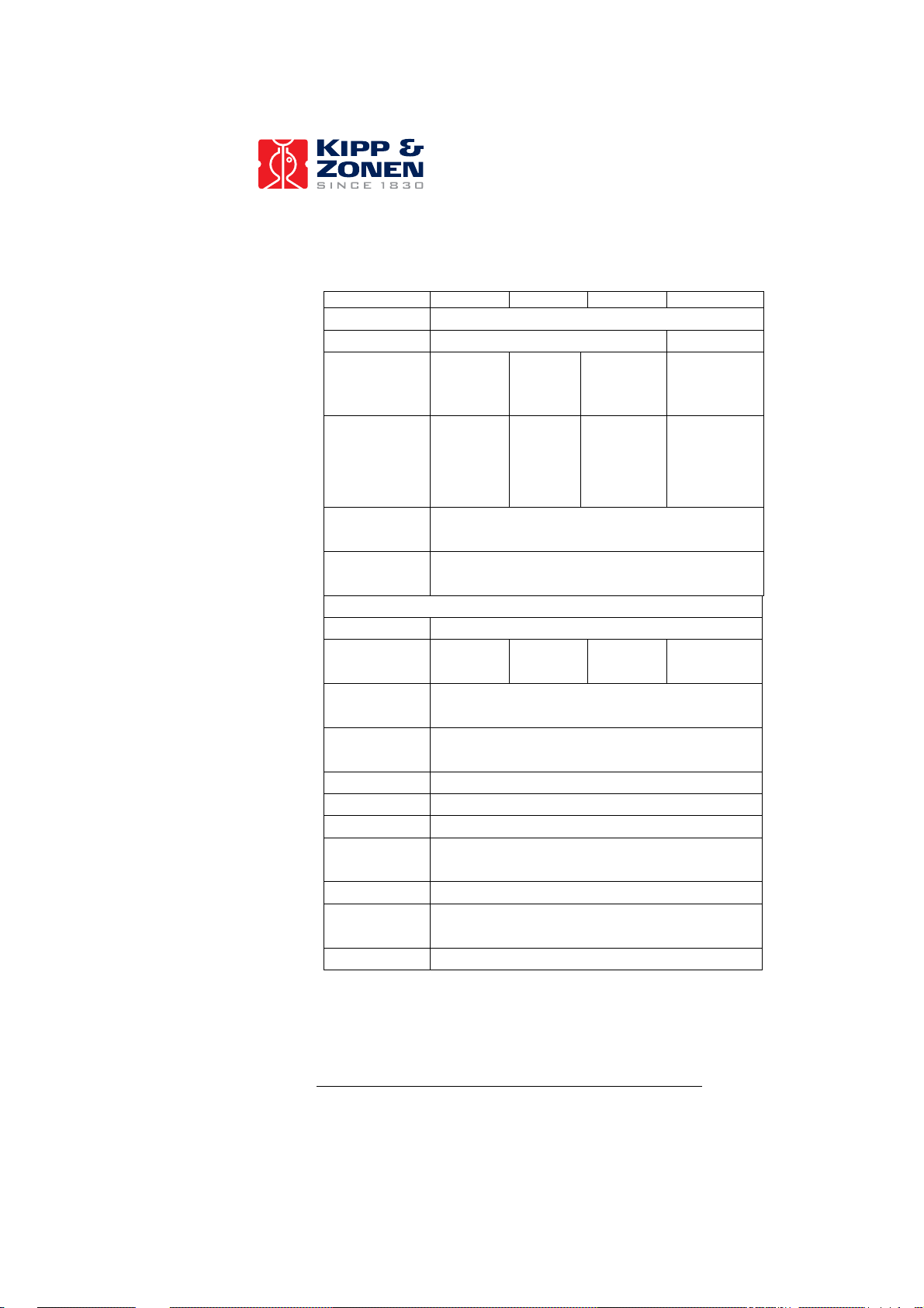
2 TECHNICAL DATA
Optical
Type Single band Dual band
UVS-A-T UVS-B-T UVS-E-T UVS-AB/AE-T
UV irradiance
measured
Nominal
spectral
response
Response at
> 400 nm
Cosine
response
Electrical
Nominal output
0 - 3 Volt
Output of
internal
Operating
temperature
Power supply 7-18 VDC, 8 W
Mechanical
Materials
Connector Binder 712 Series, 8 pole
Height
Diameter
Weight < 1 kg
UV-A UV-B
315-400
nm
< 2.5% between 0°and 70° solar zenith angle
0 – 90
W/m
- 40 °C to + 50 °C, reduced specification
Housing: protected aluminium, polyester coated
280-
315 nm
2
0 – 6
W/m2
2.5 V ~ 25 °C (see Appendix II)
- 25 °C to + 50 °C, full specification
Dome: UV-grade quartz
Erythemally
Active UV-E
ISO
17166:1999
/ CIE S
007/E-1998
< 0.1% of output
0 – 0.6
W/m2
145 mm
122 mm
UV-A + UV-B
UV-A + UV-E
See individual
radiometers
See individual
radiometers
7
Page 8

3 INSTALLATION
When installing the radiometer you must consider:
1. The radiometer should be installed as high as
possible to minimize obscuration by trees, buildings,
etc. This includes the obscuration of the indirect,
scattered radiation coming from the whole upper
hemisphere. A large portion of the received UV
radiation does not reach the radiometer directly
from the sun, but is scattered by molecules and
particles. Ideally the view should be clear to the
horizon in all directions.
2. The radiometer should be carefully levelled in the
horizontal plane. Use the built-in spirit level to find
the correct position.
3. The installation of the radiometer must ensure
natural ventilation to reduce heating of the housing
caused by solar radiation and electrical power
dissipation. If the housing becomes too hot,
damage may occur.
8
Page 9

3.1 PIN CONNECTIONS OF ALL UV VERSIONS
Pin connection scheme of the connector
[color of wire in yellow connection cable]:
1 - V+: positive supply for signal circuit,
[red] 7 - 18 V, 1 W
2 - HEAT-GND: heater ground
[blue]
3 - UV-X-OUT: UV-B or UV-E output, 0 - 3 V
[green] not connected in UVS-A-T
4 - TEMP-OUT: internal temperature output
[yellow] see table in Appendix II
5 - GNDA: ground for signal outputs
[grey]
6 - HEAT V+: positive supply voltage for heater
[brown] 7 - 18 V, 8 W
7 - UV-A-OUT: UV-A output, 0 – 3 V
[white] not connected in UVS-B-T or -E-T
8 - GNDA: ground for signal circuit
[black]
Voltage drop over connection wires:
For correct operation of the sensor it is required that
the power supply and the connection cable have a total
resistance which does not exceed a critical value R
max.
This is to prevent voltage drop over the connection
wires that will reduce the supply voltage beyond the
lower operating limit of the radiometer electronics.
9
Page 10

The formula for R
max
is:
R
= ([VT+] - 6 V) / 1.2 A
max
where [VT+] is the supply voltage and R
is the sum
max
of the total wire resistance and the internal resistance
of the power supply.
Example 1:
The supply voltage is 12 VDC. The internal resistance
of the power supply is 1 Ω (i.e. voltage drop of 1 V at 1
A load). Then the allowable total wire resistance (sum
of positive and negative supply wire) is 4 Ω.
Example 2:
To calculate the minimum voltage that is required for
correct operation of the radiometer with the standard
cable of 10 m length, the above equation has to be
reformulated as follows:
[VT+] = 1.2A • R
+ 6V
tot
where R
is the sum of the resistances (internal
tot
resistance of the power supply and total wire
resistance). With the wire resistance of 0.15Ω/m a total
wire resistance of 2 x 1.5Ω = 3Ω for the standard 10 m
cable is obtained. With an internal resistance of 1Ω
(power supply) the sum of the resistances is 4Ω
(equals R
). To compensate for the voltage drop over
tot
the wires and power supply, the voltage supply [VT+]
must be at least 10.8V. Hence, with a power supply
(internal resistance 1Ω) that provides at least 10.8V the
radiometer will operate correctly.
10
Page 11

Data logger input channels:
To prevent earth loops that influence the quality of the
data from the radiometer it is recommended to use
floating inputs to measure the output voltage signals. If
the input of the data logger is not floating it may be
useful to test the radiometer signal for noise due to
earth loops over the data logger input channels.
Connection scheme: UV series
Important notes:
- Pin 3 (green wire) is the UV-B or UV-E output.
- For single band UV-B or UV-E instruments, pin 7
(white wire) is not connected.
- The analog ground pin 5 (grey wire) should not be
grounded. This can cause ground loops and
offsets, especially when the 0 Volt of the power
supply is grounded.
11
Page 12

4 CALIBRATION AND UVIATOR SOFTWARE
From late 2007 the specially developed Kipp & Zonen
UVIATOR Software is included with all new UVS
radiometers. The use of the UVIATOR is explained in
the UVIATOR manual. In this chapter the benefits and
the principles are explained.
Why use UVIATOR software
To improve the quality and relevance of measured UV
irradiance data from UVS radiometers by taking into
account the spectral properties of the radiometer and
of the atmosphere at the time and location of the
measurement.
Theoretical Background
Atmospheric ultraviolet radiation measurements are
difficult to perform due to the drastic decrease of UV-B
irradiance towards shorter wavelengths, caused by the
strong stratospheric Ozone absorption. Besides the
extinction of UV radiation due to Ozone, Rayleigh
scattering also affects the radiation, especially in the
UV-B spectral region.
As UV radiation represents only a small portion of the
solar spectrum, broad-band UV radiometers contain
filters and use signal amplifiers to measure the UV
irradiance in the appropriate spectral region. Filters are
used to measure the UV irradiance in the UV-A or UVB spectral region, or to match as closely as possible a
specific theoretical weighting function, such as UV-E.
As the actual radiometer spectral response functions
do not correspond exactly to the theoretical weighting
functions, even for the radiometers measuring only UVA or UV-B irradiances, the measurements are affected
by a systematic error caused by spectral mismatch.
12
Page 13

The UVS Series is suitable for the measurement of UV
irradiance according to theoretically defined UV-A, B
and E spectra. In general all broad-band filter
instruments have limited performance due to the
intrinsic spectral mismatch of each sensor with respect
to the theoretical definitions of UV-A, B and E.
By knowing the spectral mismatch in detail, one can
compensate the instrument effects for different
measurement conditions. Kipp & Zonen has developed
a unique software program for post-processing and
analysis of UVS data. The UVIATOR program performs
automatically a number of UV measurement
corrections and thereby improves the measurement
quality significantly.
The spectral mismatch error correction is based on the
correction method described in the WMO Report No.
141 [Ref. 2]. Further explanations and discussions of
the spectral mismatch error are presented in a number
of publications listed at the end of this section.
4.1 UV RADIOMETER CALIBRATION AND
CORRECTION METHOD
To achieve the most accurate measurement result with
broad-band UV radiometers, the raw signals must be
transformed into UV irradiances using two “Calibration
Steps” (A and B), and an “Adjustment Step”.
Calibration Step A:
The raw signal of the instrument (in units of Volts) has
to be transformed into an irradiance (in units of W/m2).
To achieve this transformation a so-called “radiometric
calibration factor”, denoted as ρ (in units of V/W/m2),
has to be determined.
13
Page 14

Calibration Step B:
The irradiances have to be corrected for the spectral
mismatch error with “conversion factors”, denoted as γ
(no units). These conversion factors are determined
using modelled UV irradiances as a function of various
total Ozone column densities and solar zenith angles.
Adjustment Step:
The corrected UV measurements are obtained by
multiplying the raw UV radiometer reading under
outdoor measurement conditions with an appropriate
“adjustment factor”, χ, defined as 1/(ρ•γ). The
appropriate adjustment factor has to be chosen
according to the measurement conditions at the time of
the UV radiometer reading.
The Adjustment Step which provides the final,
corrected, UV irradiance (in units of W/m2) is carried
out by the UVIATOR program for each individual UVS
radiometer reading. Before the broad-band UVS
radiometer can be used in the field, it must be factory
calibrated according to Calibration Steps A and B,
which provide the calibration and correction factors for
a particular instrument.
The next two paragraphs describe Calibration Steps A
and B as they are performed at Kipp & Zonen. The final
paragraph of this chapter describes the Adjustment
Step as implemented in the UVIATOR program.
4.1.1 CALIBRATION STEP A:
DETERMINATION OF THE RADIOMETRIC
CALIBRATION FACTOR
The radiometric calibration of the broad-band UVS
radiometers is performed with a Xenon lamp, a
monochromator and a calibrated Silicon photo-diode
detector. The photo-diode and the test UVS radiometer
are mounted behind the exit slit of the monochromator.
14
Page 15

∫
∫
They are exposed to spectral irradiances between
280nm and 400nm (step increments 1 nm, slit width 2
nm at FWHM). The spectral measurements are
performed sequentially as the monochromator has one
exit slit only. Nevertheless, identical monochromator
output signals can be achieved for the photo-diode and
the UVS radiometer by positioning the sensitive
surfaces of both detectors at the same distance from
the exit slit.
A calibration factor is defined as the ratio between the
radiometer output and the radiation input, i.e. the
radiometer reading divided by the UV irradiance. To
obtain the radiometric calibration factor, ρ, in the
laboratory, the UV radiometer output and the UV
irradiance input are determined using the
monochromatic measurements.
The broad-band UV radiometer output can be
calculated according to:
U
where u
readings. u
response function. The index UVS denotes the variable
of a broad-band UVS radiometer. The radiometerweighted UV irradiance input, can be calculated as:
where e
monochromator output (measured with the photo-
diode), s
function of the test UVS radiometer (i.e.
u
(λ)/max(u
UVS
2
) of the UVS radiometer detection surface. Finally,
m
the radiometric calibration factor is obtained from the
two monochromator-based measurements (U
E
) according to ρ=U
UVS
V/(W/m2).
(λ) are the spectrally measured test UVS
UVS
UVS
E
UVS
(λ) is the irradiance (in units of W/nm) of the
Si
(λ) is the normalized spectral response
UVS
= u
UVS
(λ) is also referred to as the spectral
e
=
UVS
Si
(λ)), and A
(λ)• d
UVS
(λ)• s
UVS
A
eff
is the effective area (in
eff
UVS/EUVS
λ
(λ)• d
. The units of ρ are
λ
and
UVS
15
Page 16

4.1.2 CALIBRATION STEP B:
DETERMINATION OF THE CONVERSION
FACTOR TABLE
Without any measurement correction, a broad-band UV
radiometer can provide results that deviate by a factor
of 2 or more from the true values. The magnitude of the
deviation depends mainly on the extent of the spectral
mismatch and the measurement conditions.
The measurement conditions for which correction
factors are calculated are obtained by varying the solar
zenith angle, Θ
] in the radiative transfer model TUV [Ref. 3]. Other
[O
3
, and the total Ozone column density,
0
atmospheric parameters affecting UV irradiances, such
as extinction due to aerosols, are not explicitly included
as they are assumed to be comparatively small.
The modelled UV spectra are used to determine the
conversion factors
γ =T
where T
UVS
and T
, γ (Θ
UVS/TUVX
UVX
), which are defined as:
0,O3
denote the normalized spectral
response function-weighted irradiance and the ‘true’
irradiance, respectively:
where e
TUV
irradiance as a function of the variable input
parameters Θ
, represents the modelled irradiance weighted with
T
UVX
a theoretical spectral response function, s
a theoretical spectral response function could be the
Erythemal weighting function CIE-1987 [Ref. 4]. The
conversion factors calculated with the Erythemal
weighting function provide the corrections for the UVSE-T and UVS-AE-T radiometers.
(
λ
Θ
) denotes the TUV modelled
0,O3
and O3. Note, that the ‘true’ irradiance,
0
(λ). Such
UVX
16
Page 17

The solar zenith angles, Θ
85° (using steps of 5°) and the Ozone column
densities, [O
] are varied between 200 Dobson Units
3
(DU) and 500 DU (using steps of 10 DU), yielding 18 x
31 = 558 conversion factors. If UV irradiances have to
be measured with broad-band UV radiometer under
exceptional conditions, it is recommended to calculate
new conversion factors using model parameters that
are representative for the exceptional condition (e.g.
snow-covered land surface at a location which is
mostly snow -free).
4.2 ADJUSTMENT STEP:
UVIATOR CORRECTION METHOD
To obtain the most accurate UV irradiances using
broad band UV radiometers, the readings (“raw
radiometer output”) must be multiplied with the
adjustment factor, χ. This is a combined correction
factor, composed of the radiometric calibration factor,
ρ, and the conversion factor, γ, i.e. χ=1/(ρ•γ).
The UVIATOR program performs the required selection
of the appropriate conversion factor automatically and
corrects an instantaneous UVS measurement
according to the conditions at the time and location of
the measurement. For the selection of the conversion
factor, the parameters Θ
determined according to the measurement conditions
at the time of the UV radiometer reading.
The UVIATOR program calculates the solar zenith
angle, Θ
, for each measurement as a function of the
0
measurement location (latitude and longitude) and the
GMT of the reading. The total Ozone column density,
, is automatically retrieved from the OMI or TOMS
O
3
satellite data archives. Note, that TOMS data are daily
mean values only. UVIATOR offers plug-ins to allow
the use of other Ozone column observation data, such
as from the Kipp & Zonen Brewer.
, are varied between 0° and
0
and O3 have to be
0
17
Page 18

Finally, the UVIATOR program corrects the UVS
measurements using the appropriate solar zenith
angles and Ozone column densities and makes a new
data file.
References:
[1] WMO/GAW Report No. 120: WMO –
UMAP Workshop on Broad-Band UV
Radiometers, Garmisch-Partenkirchen,
Germany, 1996. WMO TD – No. 894.
[2] WMO/GAW Report No. 141: Report of the
LAP/COST/WMO Intercomparison of
Erythemal Radiometers, Thessaloniki,
Grece, 1999. WMO TD – No. 1051.
[3] TUV discrete ordinate radiative transfer
model, Madronich et al. 1998,
http://www.acd.ucar.edu/TUV/
[4] McKinley, A.F. and B.L. Diffey, 1987: A
reference action spectrum for ultraviolet
induced erythema in human skin. CIE J.,
6, 17-22.
[5] Schreder, J., J. Gröbner, A. Los, and M.
Blumthaler, 2004: Intercomparison of
monochromatic source facilities for the
determination of the relative spectral
response of erythemal broadband filter
radiometers. Optics Letters, 29(13).
18
Page 19

5 MAINTENANCE AND RECALIBRATION
The quartz dome should be cleaned regularly. You
may use a mild window cleansing agent which must be
generously rinsed with clear water and wiped dry with a
clean cloth.
The quartz dome can be replaced when damaged. In
order to replace the dome, loosen the 6 screws in the
outer ring and remove the ring and dome. Take care
not to touch the white diffuser. Clean the surface of the
housing and check the condition of the O-ring and replace it when necessary. Re-assemble using the new
dome and mounting ring in the reverse order.
Another periodic check is to ensure that the instrument
is level and that the silica gel is still coloured orange.
When the orange silica gel in the drying cartridge is
turned completely transparent (normally after several
months), it must be replaced by fresh silica gel as
supplied in the small refill packs. The contents of one
pack is sufficient for one complete refill.
Periodic recalibration of the sensors is recommended
and provided by Kipp & Zonen. We recommend a
recalibration interval of 12 months.
19
Page 20

6 PART NUMBERS, OPTIONS AND SPARES
PARTS
UVS RADIOMETERS
UV-S-A-T UV-A 0354920
UV-S-B-T UV-B 0354925
UV-S-E-T UV-E (Erythemally active) 0354930
UV-S-AB-T (dual band) 0354940
UV-S-AE-T (dual band) 0354945
SPARES Part No.
Extra connector without cable for UV-S-X-T 2523146
Waterproof 8 pin plug + 15 m cable 0362622
Waterproof 8 pin plug + 25 m cable 0362623
Part No.
OPTIONS Part No.
CVP 2 Power Supply for UVS radiometers
115 / 230V input, 12 VDC output
0349401
20
Page 21

APPENDIX I:
ERYTHEMAL ACTION SPECTRUM
ACCORDING TO CIE 1987 (DIN 5050)
λ[nm]
290 1.000E+00 327 0.188E-02 364 0.422E-03
291 1.000E+00 328 0.151E-02 365 0.407E-03
292 1.000E+00 329 0.141E-02 366 0.394E-03
293 1.000E+00 330 0.136E-02 367 0.380E-03
294 1.000E+00 331 0.132E-02 368 0.367E-03
295 1.000E+00 332 0.127E-02 369 0.355E-03
296 1.000E+00 333 0.123E-02 370 0.343E-03
297 1.000E+00 334 0.119E-02 371 0.331E-03
298 1.000E+00 335 0.115E-02 372 0.320E-03
299 0.805E+00 336 0.111E-02 373 0.309E-03
300 0.649E+00 337 0.107E-02 374 0.299E-03
301 0.522E+00 338 0.104E-02 375 0.288E-03
302 0.421E+00 339 0.100E-02 376 0.279E-03
303 0.339E+00 340 0.966E-03 377 0.269E-03
304 0.273E+00 341 0.933E-03 378 0.260E-03
305 0.220E+00 342 0.902E-03 379 0.251E-03
306 0.177E+00 343 0.871E-03 380 0.243E-03
307 0.143E+00 344 0.841E-03 381 0.234E-03
308 0.115E+00 345 0.813E-03 382 0.226E-03
309 0.925E-01 346 0.785E-03 383 0.219E-03
310 0.745E-01 347 0.759E-03 384 0.211E-03
311 0.600E-01 348 0.733E-03 385 0.204E-03
312 0.483E-01 349 0.708E-03 386 0.197E-03
313 0.389E-01 350 0.684E-03 387 0.191E-03
314 0.313E-01 351 0.661E-03 388 0.184E-03
315 0.252E-01 352 0.638E-03 389 0.178E-03
316 0.203E-01 353 0.617E-03 390 0.172E-03
317 0.164E-01 354 0.596E-03 391 0.166E-03
318 0.132E-01 355 0.575E-03 392 0.160E-03
319 0.106E-01 356 0.556E-03 393 0.155E-03
320 0.855E-02 357 0.537E-03 394 0.150E-03
321 0.689E-02 358 0.519E-03 395 0.145E-03
322 0.555E-02 359 0.501E-03 396 0.140E-03
323 0.447E-02 360 0.484E-03 397 0.135E-03
324 0.360E-02 361 0.468E-03 398 0.130E-03
325 0.290E-02 362 0.452E-03 399 0.126E-03
326 0.233E-02 363 0.437E-03 400 0.122E-03
Weighting
λ[nm]
Weighting
λ[nm]
Weighting
21
Page 22

APPENDIX II:
CONVERSION OF OUTPUT VOLTAGE FOR
INTERNAL TEMPERATURE
Relation between the voltage at the temperature output
(connector pin 4, yellow wire) and the internal
temperature for all models
UVS-A-T, UVS-B-T, UVS-E-T, UV-S-AB-T, UV-S-AE-T:
V °C V °C
0.5 -23 1.8 11
0.6 -19 1.9 13
0.7 -16 2.0 15
0.8 -13 2.1 17
0.9 -10 2.2 19
1.0 -7 2.3 21
1.1 -5 2.4 23
1.2 -2 2.5 25
1.3 0 2.6 27
1.4 2 2.7 29
1.5 5 2.8 31
1.6 7 2.9 34
1.7 9
3.0 36
22
Page 23

APPENDIX III: RECALIBRATION SERVICE
Solar Radiation Measurement Instruments
Kipp & Zonen solar radiation measurement instruments
comply with the most demanding international
standards. In order to maintain the specified
performance of these instruments, Kipp & Zonen
recommends calibration of their instruments every two
years. The exception to this is the UVS Series of UV
Radiometers, where recalibration is recommended
annually.
Recalibration can be carried out at Kipp & Zonen to the
original factory procedures using traceable methods.
Here, recalibration to the highest standards can be
performed at low cost. Recalibration can usually be
performed within four weeks. Urgent recalibration may
be possible in a shorter time, subject to production
scheduling restrictions.
Kipp & Zonen will confirm the date for recalibration
when the instrument is received and its condition
checked.
For your convenience we have added a form that you
can fax or e-mail to us to schedule the recalibration of
your instrument(s) at Kipp & Zonen.
23
Page 24

RECALIBRATION FORM
NAME :
COMPANY / INSTITUTE :
ADDRESS :
POST CODE + CITY :
COUNTRY :
TEL :
FAX :
E-MAIL :
I would like to receive a price list for recalibration
I would like to submit my instruments for recalibration
Type / Model Qty Requested delivery time
Fax to: +31-15-2620-351
Or
E-mail to: info@kippzonen.com
24
Page 25

Our customer support remains at your disposal for any maintenance or repair, calibration,
supplies and spares.
Für Servicearbeiten und Kalibrierung, Verbrauchsmaterial und Ersatzteile steht Ihnen unsere
Customer Support Abteilung zur Verfügung.
Notre service 'Support Clientèle' reste à votre entière disposition pour tout problème de
maintenance, réparation ou d'étalonnage ainsi que pour les accessoires et pièces de rechange.
Nuestro apoyo del cliente se queda a su disposición para cualquier mantenimiento o la
reparación, la calibración, los suministros y reserva.
HEA D OFFI CE
Kipp & Zonen B.V.
Delftechpark 36, 2628 XH Delft
P.O. Box 507, 2600 AM Delft
The Netherlands
T: +31 (0) 15 2755 210
F: +31 (0) 15 2620 351
info@kippzonen.com
SALES OFFICES
Kipp & Zonen France S.A.R.L.
7 Avenue Clément Ader
ZA Ponroy - Bâtiment M
94420 Le Plessis Trévise
France
Kipp & Zonen Asia Pacific Pte. Ltd.
81 Clemenceau Avenue
#04-15/16 UE Square
Singapore 239917
Kipp & Zonen USA Inc.
125 Wilbur Place
Bohemia
NY 11716
United States of America
Go to www.kippzonen.com for your local distributor or contact your local sales office
T:
+33 (0) 1 49 62 41 04
F: +33 (0) 1 49 62 41 02
kipp.france@kippzonen.com
T: +65 (0) 6735 5033
F: +65 (0) 6735 8019
kipp.singapore@kippzonen.com
T: +1 (0) 631 589 2065
F: +1 (0) 631 589 2068
kipp.usa@kippzonen.com
Passion for Precision
 Loading...