


 Loading...
COMBILOG 1022
Data Logger
Hardware Manual Version 1.04
Issue: 22.01.2010
Technical data are subject to change!
2 |
Hardware Manual COMBILOG 1022 |
© Copyright 1995-2010, Theodor Friedrichs & CO
(Germany).
Copyrights: Operating instructions, manuals and software are subject of copyright. Copying, duplication, translation, conversion into any electronic medium or any machine readable form, as a whole or in parts, is not permitted, with the exception of making a back-up copy of the software for saving purposes, insofar as this is technically feasible and is recommended by our company. Contraventions will lead to compensation.
Limitation of Liability: No liability is assumed by Theodor Friedrichs for damages and/or injury resulting from use of equipment supplied by this company. In no event will Theodor Friedrichs be liable for indirect or consequential damages whatsoever resulting from loss of use, data or profits arising out of connection with the use of performance of Theodor Friedrichs products. Theodor Friedrichs products are not designed, intended, or authorized for use as components and medical systems, or other applications indeed to support or sustain life, or for any other application in which the failure of the Theodor Friedrichs product(s) could create a situation where personal injury or death may occur.
Any claims against Theodor Friedrichs in connection with the hardware and software products described in this manual can exclusively be based on the guarantee regulations. Any further claims are excluded, in particular Theodor Friedrichs does not give any guarantee as to the correctness of the contents of this manual. Changes are subject to alteration and can be executed any time without advanced notice.
Trade Marks: Without going into details, we want to point out the usage of indications and entered trade marks, in particular the indications and trade marks of Microsoft Corporation, International Business Machines Corporation and Intel Corporation.
________________________________________
Hardware Manual COMBILOG 1022 |
3 |
4 |
Hardware Manual COMBILOG 1022 |
|
CHAPTER SURVEY |
|
|
|
Page |
1 |
GENERAL PRELIMINARY REMARKS............... |
10 |
2 |
SYSTEM DESCRIPTION........................................ |
12 |
3 |
INSTALLATION....................................................... |
19 |
4 |
SIGNAL PROCESSING.......................................... |
28 |
5 |
FUNCTIONAL DESCRIPTION.............................. |
34 |
6 |
DISPLAY / MENU OPERATION........................... |
60 |
7 |
DATA STORAGE..................................................... |
74 |
8 |
MASTER FUNCTION.............................................. |
81 |
9 |
INITIATION AND TEST.......................................... |
84 |
10 |
STRUCTURE OF THE BUS TOPOLOGY........... |
86 |
11 |
COMMUNICATION.................................................. |
99 |
12 |
WEBSERVER......................................................... |
144 |
13 |
SPECIFICATIONS................................................. |
147 |
14 |
SIMPLIFIED DRAWINGS.................................... |
154 |
Hardware Manual COMBILOG 1022 |
5 |
|
TABLE OF CONTENTS |
|
|
|
Page |
1 |
GENERAL PRELIMINARY REMARKS............... |
10 |
1.1 |
About this Manual.................................................................... |
10 |
1.2 |
Important Notice...................................................................... |
10 |
1.3 |
Contact for Inquiries................................................................ |
11 |
2 |
SYSTEM DESCRIPTION........................................ |
12 |
2.1 |
System Overview..................................................................... |
12 |
2.2 |
Range of Application............................................................... |
13 |
2.3 |
Features.................................................................................. |
15 |
2.4 |
Configuration Software............................................................ |
17 |
3 |
INSTALLATION....................................................... |
19 |
3.1 |
Mounting / Fixing..................................................................... |
19 |
3.2 |
Protective System.................................................................... |
19 |
3.3 |
Ambient Temperature.............................................................. |
20 |
3.4 |
Front panel / Pin Assignment.................................................. |
20 |
3.5 |
Connection ............................................................................. |
22 |
3.6 |
Power Supply.......................................................................... |
23 |
3.7 |
Bus Connection....................................................................... |
25 |
3.8 |
Sensor Connection.................................................................. |
26 |
3.9 |
Several Sensors at one Data Logger...................................... |
27 |
3.10 |
Module Jack............................................................................ |
27 |
4 |
SIGNAL PROCESSING.......................................... |
28 |
4.1 |
Analogue Inputs....................................................................... |
28 |
4.2 |
Digital Inputs/Outputs.............................................................. |
28 |
4.3 |
Power Switch........................................................................... |
29 |
4.4 |
Internal Reference Voltage, Offsetand Drift Correction......... |
30 |
4.5 |
Internal Processing.................................................................. |
31 |
4.6 |
Scan Rate and Power Consumption....................................... |
32 |
4.7 |
Signal Processing.................................................................... |
33 |
6 |
Hardware Manual COMBILOG 1022 |
5 |
FUNCTIONAL DESCRIPTION.............................. |
34 |
5.1 |
Analogue Input Channel.......................................................... |
35 |
5.1.1 |
Voltage Measurement............................................................. |
36 |
5.1.2 |
Current Measurement.............................................................. |
38 |
5.1.3 |
Resistance Measurement........................................................ |
40 |
5.2 |
Digital Input Channel............................................................... |
45 |
5.2.1 |
Digital Status Recording.......................................................... |
46 |
5.2.2 |
Frequency Measurement......................................................... |
47 |
5.2.3 |
Progressive Counter................................................................ |
49 |
5.3 |
Digital Output Channel............................................................ |
50 |
5.3.1 |
Digital Status Output:............................................................... |
50 |
5.4 |
Arithmetic Channel.................................................................. |
52 |
5.5 |
Setpoint Channel..................................................................... |
58 |
5.6 |
Alarm Channel......................................................................... |
58 |
5.7 |
Serial Channel......................................................................... |
58 |
5.8 |
Threshold Values..................................................................... |
58 |
5.9 |
Error Handling......................................................................... |
59 |
6 |
DISPLAY / MENU OPERATION........................... |
60 |
6.1 |
Display and Operation............................................................. |
60 |
6.2 |
Menu Items.............................................................................. |
60 |
6.3 |
SD-Card................................................................................... |
72 |
6.3.1 |
Remove Card.......................................................................... |
72 |
6.3.2 |
Firmware Update..................................................................... |
73 |
7 |
DATA STORAGE..................................................... |
74 |
7.1 |
General Remarks to Data Storage.......................................... |
74 |
7.2 |
Modes of Data Storage............................................................ |
74 |
7.3 |
Storage Medium...................................................................... |
75 |
7.4 |
Internal Data Storage.............................................................. |
76 |
7.5 |
External Data Storage with SD Card....................................... |
78 |
8 |
MASTER FUNCTION.............................................. |
81 |
8.1 |
Master Function....................................................................... |
81 |
Hardware Manual COMBILOG 1022 |
7 |
9 |
INITIATION AND TEST.......................................... |
84 |
9.1 |
Before Connecting the Device................................................. |
84 |
9.2 |
After Connecting the Device.................................................... |
84 |
9.3 |
Configuration of the Data Logger............................................ |
84 |
10 |
STRUCTURE OF THE BUS TOPOLOGY........... |
86 |
10.1 |
Bus Interface........................................................................... |
87 |
10.2 |
Bus Structure........................................................................... |
88 |
10.3 |
Transmission Speed and Line Length..................................... |
89 |
10.4 |
Bus Cable................................................................................ |
90 |
10.5 |
Bus Plug.................................................................................. |
91 |
10.6 |
Bus Termination...................................................................... |
92 |
10.7 |
Shielding.................................................................................. |
94 |
10.8 |
PC Bus Connection................................................................. |
95 |
10.9 |
Potential Equalization.............................................................. |
96 |
10.10 |
Adjustment of Address and Baud Rate................................... |
96 |
11 |
COMMUNICATION.................................................. |
99 |
11.1 |
Bus Interface........................................................................... |
99 |
11.2 |
Bus Protocol............................................................................ |
99 |
11.3 |
Data Format........................................................................... |
100 |
11.4 |
Output Format....................................................................... |
101 |
11.5 |
Transmission Sequence........................................................ |
104 |
11.6 |
ASCII protocol....................................................................... |
106 |
11.6.1 |
Telegram Format for the ASCII Protocol............................... |
106 |
11.6.2 |
Instruction Set in the ASCII-Protocol..................................... |
109 |
11.7 |
PROFIBUS protocol.............................................................. |
116 |
11.7.1 |
Telegram Format for the Profibus Protocol........................... |
116 |
11.7.2 |
Instruction Set in the PROFIBUS-Protocol............................ |
120 |
11.8 |
MODBUS protocol................................................................. |
128 |
11.8.1 |
Telegram Format for the MODBUS-RTU Protocol................ |
128 |
11.8.2 |
Instruction Set in MODBUS-RTU Protocol............................ |
129 |
11.9 |
Sample Program.................................................................... |
140 |
11.10 |
Autocall Function................................................................... |
141 |
8 |
Hardware Manual COMBILOG 1022 |
11.11 |
Modem Connection............................................................... |
143 |
12 |
WEBSERVER......................................................... |
144 |
12.1 |
General.................................................................................. |
144 |
12.2 |
System Info............................................................................ |
144 |
12.3 |
System Log............................................................................ |
144 |
12.4 |
Data View.............................................................................. |
144 |
12.5 |
Data Logger........................................................................... |
145 |
12.6 |
Configuration / Login............................................................. |
145 |
12.7 |
Single Channel Configuration................................................ |
145 |
12.8 |
Power Switch......................................................................... |
145 |
12.9 |
Serial Channel....................................................................... |
145 |
12.10 |
Logger Configuration............................................................. |
146 |
12.11 |
Password............................................................................... |
146 |
12.12 |
Protocol................................................................................. |
146 |
12.13 |
Logout.................................................................................... |
146 |
13 |
SPECIFICATIONS................................................. |
147 |
13.1 |
Power Supply........................................................................ |
147 |
13.2 |
Signal Inputs/Outputs............................................................ |
147 |
13.3 |
Signal Processing.................................................................. |
147 |
13.4 |
Analogue Inputs (8 per Module)............................................ |
148 |
13.5 |
Digital Inputs/Outputs (6 per Module).................................... |
149 |
13.6 |
Interfaces............................................................................... |
149 |
13.7 |
Operating Conditions............................................................. |
151 |
13.8 |
Electromagnetic Compatibility............................................... |
151 |
13.9 |
Shell....................................................................................... |
152 |
13.10 |
Circuit.................................................................................... |
152 |
13.11 |
Accessories / Notice for Orders............................................. |
152 |
14 |
SIMPLIFIED DRAWINGS.................................... |
154 |
14.1 |
Front View............................................................................. |
154 |
Hardware Manual COMBILOG 1022 |
9 |
1GENERAL PRELIMINARY REMARKS
1.1About this Manual
The manual contains all important information concerning the function, installation and initiation of the data logger
COMBILOG 1022.
The description of the configuration software for the COMBILOG-System is available as Online-Help within the configuration software COMBILOG.EXE.
1.2Important Notice
Make sure to use the data logger COMBILOG 1022 exclusively in accordance with the notices, technical data and operating conditions mentioned in this manual. In case of inexpert handling or wrong application possible disturbances, measuring errors, effects on or from other appliances and facilities as well as possible endangering of human lives or tangible assets cannot be excluded!
Therefore if you have not yet operated the data logger COMBILOG 1022, you should first of all study this manual thoroughly. While initiating or operating the appliance or in case service is required always observe the notices given in this manual.
Please note further that there are other special regulations to be observed in case of application in potentially explosive surroundings (EExe, EExi, ...). These, however are not subject of
10 |
Hardware Manual COMBILOG 1022 |
this manual, which only explains the general use of the data logger COMBILOG 1022.
1.3Contact for Inquiries
In case of inquiries concerning the data logger COMBILOG 1022 please contact your local distributor or directly Theodor Friedrichs & Co. GmbH.
Hardware Manual COMBILOG 1022 |
11 |
2SYSTEM DESCRIPTION
2.1System Overview
The COMBILOG 1022 is a data logger with compact design, combined with integrated LC-display and memory slot suitable for SD cards.
This data logger was developed for meteorological, hydrological and environmental measuring systems, but it is equally suitable for countless further applications in industrial production.
The COMBILOG 1022 features high performance, compact design (SMD components), low power consumption and moderate price.
The data logger is equipped with 8 analogue and 6 digital measuring channels; further channels for numeric calculation may be configured. Four serial interfaces RS232, RS485, USB and Ethernet are built-in, featuring communication via ASCII, PROFIBUS or MODBUS. Data storage is achieved by internal Flash or SD memory card, optionally.
„SELECT“ switch and 4-line LCD on the front panel allow to enter or modify a number of different modes and functions, such as scan rate and averaging time, as well as offset or gain. The COMBILOG 1022 can easily be mounted on a 35 mm standard rail using its „snap-in“ clamp and is therefore suitable for control cabinet installation or similar.
Thanks to its low power consumption, battery supplied systems are possible, whereby the use of a solar panel enables any extension of measuring period.
12 |
Hardware Manual COMBILOG 1022 |
For applications like outdoor use there is a version with stainless steel housing available, as well as various other accessories.
Configuring of the data logger is accomplished by means of an easy to handle WINDOWSTM 98 / ME / NT / 2000 / XP software.
2.2Range of Application
As described under (2.1), the most varying measurement tasks can easily be accomplished by means of the COMBILOG 1022. Some typical applications are e.g. measurement of temperature via resistance thermometers (Pt100), operation with combined sensors with currentor voltage output (e.g. wind speed measurement with DC generator) or position measurement and weight measurement by displacement transducers and force transducers. With these applications the data logger COMBILOG 1022 supports measuring methods with 2-, 3- and 4-wire technique. The signal processing required in accordance with the sensors used, such as gain, linearisation, offset correction etc. can be adjusted individually by software. An external amplifier is not required.
The digital signal inputs can be used, for example, to connect switches, initiators, digit emitters and oscillators. Thus status indications can be collected and tasks like e.g. position measurements, displacement measurements, angular measurements, frequency measurements and timings can be carried out. Furthermore special 8-bit-Graycode-transmitters can be connected.
Special calculations of measured values are possible by arithmetic channels. In case the 8 analogue and 6 digital inputs are not sufficient, other modules can be connected to the data
Hardware Manual COMBILOG 1022 |
13 |
logger via the RS485 bus. In this case the COMBILOG is used as a bus master to read the measured values from the slave modules.
All data can be transmitted via the integrated RS485 communication interface to a subsequent control (PLC) or to a computer (PC). Up to 127 modules can be connected with the twowire line over distances of several km. At the same time the communication interface features programming and configuring the individual application from a PC.
If the data logger COMBILOG 1022 is not integrated in a bus, an additional RS232-interface is available for the user. This interface allows only a point-to-point connection up to max. 20 m (65 feet), but all functions of the RS485-interface remain available.
Furthermore the data logger can send messages in case of user definable conditions automatically via modem or SMS.
A configuration program is included (requires Microsoft WINDOWS 98,ME,NT,2000, XP).
14 |
Hardware Manual COMBILOG 1022 |
2.3Features
Function:
Measurement inputs for all common types of sensors for I, U and R.
Several different sensors can be connected simultaneously
Measured values monitored by programmable thresholds
Detection of sensor errors
Detection of communication errors
Programmable error handling
Calculation of average values, minima, maxima, standard deviation and other arithmetic functions
7 MByte Flash internal data storage, extendible with external SD card
Inputs and outputs:
8 analogue inputs (for 2-, 3- and 4-wire connection)
6 digital inputs/outputs (I/O ports), configurable
Power supply:
Power supply: +10 ... +30 VDC
All connections protected against excess voltage, excess current and reverse polarity
Battery operation is possible due to low power consumption
Display and operation:
LED-status indication for digital inputs/outputs
LED-status indication for malfunction and operation (ERR / RUN)
Hardware Manual COMBILOG 1022 |
15 |
LED-status indication for the ethernet interface
LC-display (4 x 16 characters) and push-/turn knob for operation
Measured value processing:
Linearisation, scaling and conversion into physical units
Option to adjust, modify or reset the processing parameters individually
Master function to retrieve data from external modules
Programmable averaging
Automatic message transmission via modem or SMS
Non-volatile storage for program, parameters and data
Configuration:
Configurable with PC-software under WINDOWS™ 98 / ME / NT / 2000 / XP
Menu-guided sensor selection in plain text
Free configuration of up to 32 channels
Data base for the most common sensors
Definition of user-specific sensors
Setting of type and principle of measurement
Display of pin assignment
Input of linearisation
Alarm settings
Programmable error handling
Arithmetic combination of sensor channels
Configurable measuring rate and averaging interval
Configuration on file (offline-operation)
Configuration via bus (online-operation)
Programming:
Allocation of address and baud rate via bus
Password to save the configuration and the data memory
Synchronizing of date and time with the host PC
16 |
Hardware Manual COMBILOG 1022 |
Communication:
Integrated RS 485, RS 232, USB and Ethernet communication interface
Autonomous function independent of subsequent systems
Definition of the transmission protocol (ASCII and PROFIBUS or MODBUS)
Definition of the telegram format (baudrate and parity)
Definition of the output format (field length / decimals / unit)
Simple instruction set
Shell:
Compact structural shape
Attractive design
Fast mounting
Snap-on mounting on DIN rail 35 mm / 1.4 inch
Protection IP20
Plug-in screwed terminals
Module jack, ground connection
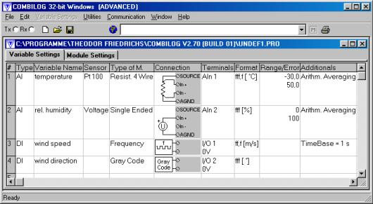
2.4Configuration Software
The COMBILOG 1022 is delivered with a configuration software for MS WINDOWS 98/ME/NT/2000/XP. This software allows the individual configuration of the data logger.
Measuring channels are defined as variables in a variable table.
Predefined sensors can be selected from the integrated database. The linearisation of the sensor signals will be performed automatically. Additional sensors can be defined.
Additional parameters like scan rate, averaging interval, data recording, error handling, automatic message generation, master function etc. are configurable. A password enables protection of the configuration and the stored data. Instantaneous measured values can be watched directly.
Hardware Manual COMBILOG 1022 |
17 |
In case a software update for the data logger is necessary, the configuration program provides a download function, that sends the new program to the logger.
Communication is supported via standard interface (RS232), telephone or GSM modem or TCP/IP protocol.
Example for a configuration:
18 |
Hardware Manual COMBILOG 1022 |
3INSTALLATION
3.1Mounting / Fixing
The data logger COMBILOG 1022 has a snap-on mounting for installation on standard profile rails 35 mm (1.4 inch) according to DIN EN 50022.
Installation on the DIN rail is performed by means of the four straps on the rear side of the data logger. First push the two straps on the bottom behind the notch of the DIN rail and then press the data logger on the DIN rail until the two straps on the top snap in.
In order to take the data logger off the DIN rail slide the module lateral off the rail or in case it is not possible lift the data logger slightly so that the straps on the top get off the notch and the data logger can be taken off easily by pulling.
Attention: Refer to protection earth hints in chapter 3.5!
3.2Protective System
The data logger has an IP20 protective system. For outdoor installations data logger COMBILOG 1022 can be installed in a stainless housing type 9920, thus featuring IP66 standard.
Hardware Manual COMBILOG 1022 |
19 |

3.3Ambient Temperature
The admissible ambient temperature for the data logger COMBILOG 1022 is -45 °C to +85 °C. The admissible ambient temperature for the LC-Display is between -20°C and +60°C and becoming very slow below 0°C.
Attention: For certain memory card types, differing temperature ranges have to be considered.
3.4Front panel / Pin Assignment
The front panel of the data logger COMBILOG 1022 shows following elements:
1 |
2 |
3 |
4 |
5 |
6 |
7 |
8 |
16 |
9 |
15 |
14 |
13 |
12 |
11 |
10 |
9 |
Figure 3.1 Front panel
20 |
Hardware Manual COMBILOG 1022 |
Description of the parts:
Number |
Description |
|
|
1 |
USB |
|
|
2 |
Ethernet |
|
|
3 |
Voltage supply |
|
|
4 |
Power switch |
|
|
5 |
RS485 |
|
|
6 |
RS232 |
|
|
7 |
6 digital I/Os |
|
|
8 |
Status-LEDs for digital I/Os |
|
|
|
|
Number |
Description |
|
|
9 |
Module jack connection |
|
|
10 |
LED ERR (red) |
|
|
11 |
LED RUN (green) |
|
|
12 |
Ethernet Link / Traffic |
|
|
13 |
Press/rotary knob |
|
|
14 |
8 analogue inputs |
|
|
15 |
LC-display |
|
|
16 |
Interface for memory card |
|
|
|
|
Table 3.1 Description of the parts on the front of the device
Pin assignment:
Terminal |
Assignment |
|
|
+10..30V |
Voltage supply + |
|
|
0V |
Voltage supply - |
|
|
A |
RS485-bus interface A |
|
|
B |
RS485-bus interface B |
|
|
RX |
RS232 receive |
|
|
TX |
RS232 transmit |
|
|
COM |
RS232 ground |
|
|
|
|
Terminal |
Assignment |
|
|
I/O + |
Digital I/O 1…6 |
|
|
0 V |
Ground for digital I/Os |
|
|
SOURCE |
Source output |
|
|
In+ |
Analogue input + |
|
|
In- |
Analogue input - |
AGND Ground for analogue input
 UOUT 1 / 2 Power switch output
Table 3.2 Pin assignment |
|
Hardware Manual COMBILOG 1022 |
21 |
3.5Connection
Connection:
Nominal cross section:
Length of wire stripping :
Alternatively available:
Protection earth:
plug-in screw terminals 1.5 mm² (0.02 square inch)
unifilar/fine-strand (AWG 16) 6 mm (0.2 inch) LP-terminals (spring loaded) (upon request)
6.3mm series tabs at rear side of housing
The best way to pull off the screw terminals is to use a small screwdriver, placed as a lever between terminal and the front of the data logger.
Not more than 2 leads should be connected with one clamp. In this case the leads should have the same conductor cross section.
Note: Wire connection is only allowed during power off.
Note: In order to avoid influences from noise on the sensor signals shielded wires should be used for the power supply, the bus connection and the signal lines.
ATTENTION: Before final installation, a suitable protection earth cable with terminal has to be connected to the ground connector at the back of the data logger. Assure that the connection has a low impedance after mounting.
22 |
Hardware Manual COMBILOG 1022 |
3.6Power Supply
U+
VersoPowergungsspannungSupply
U-
Figure 3.2 Connection of the distribution voltage
Voltage range
+10 ... +30 VDC
Power input
0.1 W typical (up to 1.1W maximum, depending on configuration)
Internal protector (reversible)
excess current 0.5 A M
excess voltage
Hardware Manual COMBILOG 1022 |
23 |
Non-regulated DC voltage between +10 and +30 VDC is sufficient for the power supply of the data logger COMBILOG 1022. The input is protected against excess voltage and current and against reverse polarity. The power consumption remains approximately constant over the total voltage range, due to the integrated switching controller.
Due to its low current consumption (max. 110 mA at 12 VDC) the data logger can also be remote-fed via longer lines. Several data loggers can be supplied parallel within the admissible voltage range, considering the voltage drop in the lines. The supply lines can also be installed in one common cable, together with the bus line, if required.
In order not to charge the data logger’s supply voltage unnecessarily, a separate power supply for sensors with a large current requirement is recommended.
24 |
Hardware Manual COMBILOG 1022 |
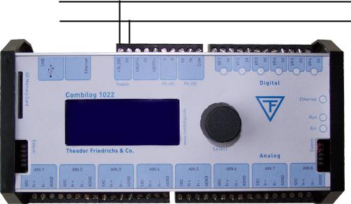
3.7Bus Connection
In general the data logger is connected to the bus by applying the signal leads A and B of the incoming bus cable and A' and B' of the outgoing bus cable together to one terminal on the module (figure 3.3).
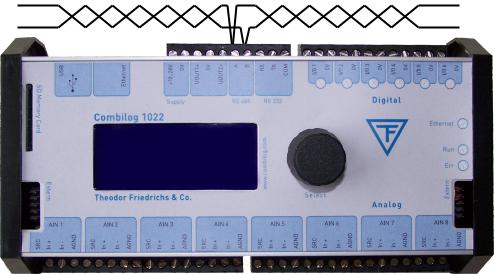
Alternatively the bus can also be connected by a "stub cable" as shown in figure 3.4.
Owing to the removable terminal, the bus connection to other data loggers remains valid, even if one data logger is replaced by another.
A
B
Figure 3.3 Connection of the data logger to the bus
Note: When connecting the logger to the bus, the two bus interfaces A and B must not be interchanged.
Note: The stub cable should be as short as possible, not longer than 30 cm (12 inch).
Hardware Manual COMBILOG 1022 |
25 |
A
B
Figure 3.4 Connection of the data logger to the bus by a stub cable
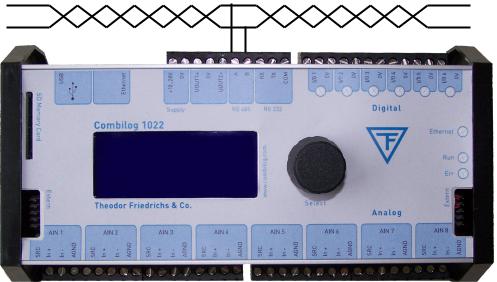
3.8Sensor Connection
The analogue and digital signal inputs and outputs are wired according to measurement task, to the transducer (sensor) that is used, and to the number of connected sensors. The pinout arrangements for the various types of measurement are described in chapter 5. The respectively valid pin assignment is determined by means of the configuration software.
Since the digital outputs are "passive" the processing of external elements always requires an external current supply. In case of larger loads this should be independent of the data logger supply.
At the connection of inductive loads a connection with a diode is required in order to prevent possible damages by induced voltage.
26 |
Hardware Manual COMBILOG 1022 |
Following devices can be connected directly to the digital outputs: signal lamps, small relays, switching relays for larger loads, acoustic signal installations, buzzer respectively beeper etc., as long as the connected loads are not exceeding the values described in the technical data chapter 12.
3.9Several Sensors at one Data Logger
The data logger COMBILOG 1022 can simultaneously receive and process sensor signals from several different sensors. As many sensors can be connected as there are analogue and digital signal inputs and outputs available (14 sensors max.; 8 analogue and 6 digital sensors).
3.10Module Jack
The data logger COMBILOG 1022 has a bus connection facility on the left and on the right side of the housing, featuring interconnection of the +10…30 VDC supply and the bus signal, for several COMBILOG.
This kind of bus connection and of power supply is particularly advantageous if several data loggers are mounted on one common profile rail side by side. In this case the connection via the terminals can be dropped, except for one module.
Note: If some COMBILOG 1022 are connected using the module jacks, the supply power has to be provided using the screw terminals. The power supply via the module jacks has to be used only for expansion modules.
Hardware Manual COMBILOG 1022 |
27 |
Note: It is necessary to take care that the current at the Module Jack is not higher than permitted. Thus, the power supply preferably should be led to the centre of the module line. For the same reason a 100 mA self resettable fuse protects the module connector of the COMBILOG 1022 against short circuits.
The permanent current drawn from the module connector shall not be higher than 100 mA.
28 |
Hardware Manual COMBILOG 1022 |
4SIGNAL PROCESSING
The data logger COMBILOG 1022 has eight analogue inputs and six digital inputs/outputs. Several different sensor signals as well as digital inputs and digital output signals can be connected and processed simultaneously.
4.1Analogue Inputs
The analogue inputs serve to collect sensor signals, or to acquire control values respectively. They are particularly designed to measure voltages, currents and resistances.
There are 8 equal analogue inputs, each input can be configured individually.
Note: Overloads of more than ± 10 VDC will lead to false measuring results in the according analogue input channel. Overloads of more than ± 15 VDC will also have influence on the measuring accuracy of the other input channels!
4.2Digital Inputs/Outputs
The six digital inputs/outputs of the data logger can be configured - independent of each other - as inputs or as outputs. The current status (in/out) is signalized by one LED each.
Hardware Manual COMBILOG 1022 |
29 |
As inputs the I/Os can be used for collecting feed-back signals, for measuring frequencies, as counters or for receiving special serial 8-bit-Graycode signals. Status information can be issued by the outputs. Thereby host-controlled or process-controlled status outputs are possible.
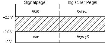
The digital inputs have an excess voltage protection (transil diodes), with nominal threshold 30 V. Input voltages between 2.0 VDC and 30 DC are interpreted as logic LOW ("0"), input voltages lower than 0.9 V as logic HIGH ("1"). The maximum input current is 1.5 mA.
Signal level |
|
Logical level |
|
|
|
Figure 4.1 Definition of signal levels and logic levels
The outputs are open-collector type with a maximum voltage of 30 VDC and a maximum current of 100 mA.
4.3Power Switch
The data logger Combilog 1022 has two power switches which act as voltage supplies for external sensors.
A power switch can be assigned to an analogue channel and configured with a lead time (see chapter Power Switch ).
The supply is switch on with a configurable time before the selected analogue input channel will be measured.
30 |
Hardware Manual COMBILOG 1022 |
Loading...