

Page 1

Instruction Manual
SHP1 • Smart Pyrheliometer
Page 2

Instruction Manual - SHP1 - Smart Pyrheliometer
2
Page 3

Important User Information
.
Dear customer, thank you for purchasing a Kipp & Zonen instrument. It is essential that you read this manual completely for a
full understanding of the proper and safe installation, use, maintenance and operation of your new SHP1 pyrheliometer.
We understand that no instruction manual is perfect, so should you have any comments regarding this manual we will be
pleased to receive them at:
Kipp & Zonen B.V.
Delftechpark 36, 2628 XH Delft, - or
P.O. Box 507, 2600 AM Delft,
The Netherlands
T: +31 (0) 15 2755 210
F: +31 (0) 15 2620 351
support@kippzonen.com
www.kippzonen.com
Warranty and liability
Kipp & Zonen guarantees that the product delivered has been thoroughly tested to ensure that it meets its published specifications.
The warranty included in the conditions of delivery is valid only if the product has been installed and used according to the
instructions supplied by Kipp & Zonen.
Kipp & Zonen shall in no event be liable for incidental or consequential damages, including without limitation, lost profits, loss
of income, loss of business opportunities, loss of use and other related exposures, however incurred, rising from the faulty and
incorrect use of the product.
Modifications made by the user may aect the instrument performance, void the warranty, or aect the validity of the CE
declaration or other approvals and compliances to applicable International Standards.
Copyright © 2014 Kipp & Zonen B.V.
All rights are reserved. No part of this publication may be reproduced, stored in a retrieval system or transmitted, in any form
or by any means, without authorisation by Kipp & Zonen.
Kipp & Zonen reserves the right to make changes to this manual, brochures, specifications and other product documentation
without prior notice.
Manual document number: V1405
st
Publication date: 1
May 2014
Instruction Manual - SHP1 - Smart Pyrheliometer
3
Page 4

Instruction Manual - SHP1 - Smart Pyrheliometer
4
Page 5

Declaration of Conformity
.
We Kipp & Zonen B.V.
Delftechpark 36, 2628 XH Delft
P.O. Box 507, 2600 AM Delft
The Netherlands
Declare under our sole responsibility that the products:
Models SHP1
Type Smart Pyrheliometer
to which this declaration relates are in conformity with European Harmonised Standards as published in:
Official Journal of the EC, Issue: C288 (30-09-2011)
The compliance of the product has been based on:
Emissions EN 61326-1:2006
Immunity EN 61326-1:2006
following the provisions of the directive:
EMC-directive 2004/108/EC
st
Delft, 1
B.A.H. Dieterink
President
Kipp & Zonen B.V.
August 2012
Instruction Manual - SHP1 - Smart Pyrheliometer
5
Page 6

Instruction Manual - SHP1 - Smart Pyrheliometer
6
Page 7

Table of Contents
.
Important User Information
.
3.........................................................................................................................................................................................
.
3
Declaration of Conformity
Table of Contents
1 Introduction
1.1 Product overview
1.1.1 The SHP1 pyrheliometer
1.1.2 International Standards
......................................................................................................................................................................................................................
....................................................................................................................................................................................................................
...............................................................................................................................................................................................
...............................................................................................................................................................................................................
.....................................................................................................................................................................................................
.....................................................................................................................................................................................................
1.2 Key parts of the SHP1 pyrheliometer
2 Installation
2.1 Included with the product
2.2 Tools required
2.3 Location and support
2.3.1 Location
2.3.2 Mounting
2.3.3 Fitting the connector and cable
2.4 Electrical connections
2.5 Power connection
2.6 Data connection
2.7 Analogue output connection
2.8 Calculations
2.8.1 Calculation 0 to 1 Volt version
2.8.2 Calculation 4 to 20 mA version
2.8.3 Recommended cable types
........................................................................................................................................................................................................................
..........................................................................................................................................................................................
......................................................................................................................................................................................................................
......................................................................................................................................................................................................
......................................................................................................................................................................................................................................
....................................................................................................................................................................................................................................
.....................................................................................................................................................................................
....................................................................................................................................................................................................
...............................................................................................................................................................................................................
...................................................................................................................................................................................................................
......................................................................................................................................................................................
............................................................................................................................................................................................................................
.......................................................................................................................................................................................
......................................................................................................................................................................................
................................................................................................................................................................................................
..................................................................................................................................................................
5
7
9
9
9
10
10
11
11
12
12
12
12
12
13
13
14
15
16
16
16
16
3 Accessories
3.1 Cables
.........................................................................................................................................................................................................................................
.......................................................................................................................................................................................................................
4 Software installation and configuration
4.1 Set up communication
4.2 Change the Modbus® address
4.3 Instrument data
4.4 Chart
4.5 Data logging
...........................................................................................................................................................................................................................................
..........................................................................................................................................................................................................................
5 Operation and measurement
5.1 Data collection
5.2 Key parts of SHP1 pyrheliometer
5.2.1 Window
5.2.2 Detector
5.2.3 Housing
5.2.4 Drying cartridge
5.2.5 Cable and connector
........................................................................................................................................................................................................................................
......................................................................................................................................................................................................................................
.......................................................................................................................................................................................................................................
6 Maintenance and re-calibration
6.1 Daily maintenance
6.2 Monthly maintenance
6.3 Yearly maintenance
6.4 Calibration
6.4.1 Calibration principle
6.4.2 Calibration traceability to the WRR
.............................................................................................................................................................................................................................
...................................................................................................................................................................................................
..................................................................................................................................................................................
.................................................................................................................................................................................................................
......................................................................................................................................................................
....................................................................................................................................................................................................................
..........................................................................................................................................................................
....................................................................................................................................................................................................................
............................................................................................................................................................................................................
..............................................................................................................................................................
...........................................................................................................................................................................................................
....................................................................................................................................................................................................
.........................................................................................................................................................................................................
...........................................................................................................................................................................................................
............................................................................................................................................................................
.......................................................................................................................................
17
17
19
20
20
21
22
23
25
25
25
25
26
26
26
26
27
27
27
27
27
27
28
7
Page 8

.
7 Specifications
.
.................................................................................................................................................................................................................
7.1 Optical and electrical
7.2 Dimensions
..............................................................................................................................................................................................................................
.....................................................................................................................................................................................................
.
29
29
29
8 Trouble shooting
8.1 Output signal not present or incorrect
8.2 Frequently Asked Questions
9 Customer Support
10. Keyword index
Appendices
A. Modbus®
A.1 Modbus® commands
A.2 Input registers
A.3 Holding registers
A.4 Read input register
A.5 Discrete inputs
A.6 Coils
A.7 Read write holding registers
A.8 Read discrete inputs
A.9 Read write discrete coils
A.10 Requesting serial number
A.11 Simple demonstration program
B. Pyrheliometer physical properties
B.1 Spectral range
B.2 Sensitivity
B.3 Response time
B.4 Non-linearity
B.5 Tempearture dependence
B.6 Operating temperature
B.7 Field of view
B.8 Maximum irradiance
B.9 Non-stability
B.10 Spectral selectivity
B.11 Environmental
B.12 Uncertainty
.......................................................................................................................................................................................................................................
...................................................................................................................................................................................................................................
..............................................................................................................................................................................................................................................
..........................................................................................................................................................................................................................
..................................................................................................................................................................................................................................
............................................................................................................................................................................................................................
.............................................................................................................................................................................................................................
.............................................................................................................................................................................................................................
...............................................................................................................................................................................................................................
........................................................................................................................................................................................................
.............................................................................................................................................................
.....................................................................................................................................................................................
....................................................................................................................................................................................................
.............................................................................................................................................................................................................
.............................................................................................................................................................................................................
........................................................................................................................................................................................................................
...................................................................................................................................................................................................................
...............................................................................................................................................................................................................
........................................................................................................................................................................................................................
...........................................................................................................................................................................................
............................................................................................................................................................................................................
...................................................................................................................................................................................................
.................................................................................................................................................................................................
.....................................................................................................................................................................................
.......................................................................................................................................................................
.........................................................................................................................................................................................................................
..................................................................................................................................................................................................
.......................................................................................................................................................................................................
.............................................................................................................................................................................................................
...............................................................................................................................................................................................................
.........................................................................................................................................................................................................................
C. Pyrheliometer classification to ISO 9060:1990
......................................................................................................................................
31
31
31
33
35
37
37
37
37
39
39
42
42
43
43
44
45
45
47
47
47
47
47
47
47
48
48
48
48
48
49
49
Using this table
Click on any item in the table of contents to be taken directly to the relevant page.
Click on the Kipp & Zonen logo at the bottom of any page to be taken back to the table of contents.
8
Page 9

1. Introduction
.
Throughout this manual the following symbols are used to indicate to the user important information.
General warning about conditions, other than those caused by high voltage electricity, which may result in physical
injury and/or damage to the equipment or cause the equipment to not operate correctly.
Note Useful information for the user
1.1 Product overview
According to International Standard ISO 9060:1990 and the World Meteorological Organization (WMO) a pyrheliometer is the
designated type of instrument for the measurement of direct solar radiation. The SHP1 pyrheliometer is compliant with the
“First Class” class specified by the international standards.
This manual, together with the instruction sheet, provides information related to the installation, maintenance, calibration,
product specifications and applications of the SHP1 pyrheliometer.
If any questions should remain, please contact your local Kipp & Zonen representative or e-mail the Kipp & Zonen customer and
product support department at: support@kippzonen.com
Please go to www.kippzonen.com for information about other Kipp & Zonen products, or to check for any updates to this manual
or software.
1.1.1 The SHP1 pyrheliometer
SHP1 pyrheliometer is a high quality radiometer designed for measuring direct short-wave irradiance (radiant flux, W/m²) which
results from the radiant flux from a solid angle of 5 degrees.
SHP1 pyrheliometer features internal digital signal processing and interfaces optimised for industrial data acquisition and control
systems. Kipp & Zonen has developed a smart interface that features RS-485 Modbus® data communication for connection to
programmable logic controllers (PLC’s), inverters, digital control equipment and the latest generation of data loggers. Amplified
Voltage or Current outputs are also included for devices that have high-level analogue inputs or current loop interfaces.
The SHP1 is available in two versions. The SHP1-V has an analogue voltage output of 0 to 1 V, the SHP1-A has an analogue current
output of 4 to 20 mA. Both have a 2-wire RS-485 interface with Modbus® (RTU) protocol. Both versions have minimised power
consumption and are protected against short circuit and reversed polarity. The digital signal processing provides faster response
times and, with an integrated temperature sensor, individual corrections for the temperature dependence of the detector are made.
To achieve the required spectral characteristics SHP1 uses a quartz window and thermopile detector. The waterproof connectors
have gold-plated contacts.
The pyrheliometer is normally delivered with a waterproof plug pre-wired to a high quality signal cable, typically this is 10 m
long but other lengths are available. The instruments can also be ordered with a plug only, for the user to fit their own cable.
Instruction Manual - SHP1 - Smart Pyrheliometer
9
Page 10
.
1.1.2 International Standard
For the SHP1 Second Class pyrheliometer ISO standard ISO 9060 applies.
Fully compliant with all ISO 9060:1990 specification criteria for an ISO Second Class pyrheliometer, the SHP1 features a
thermocouple sensing element. An integrated temperature sensor with active and individual measured temperature compensation
is included for improved temperature dependence of sensitivity.
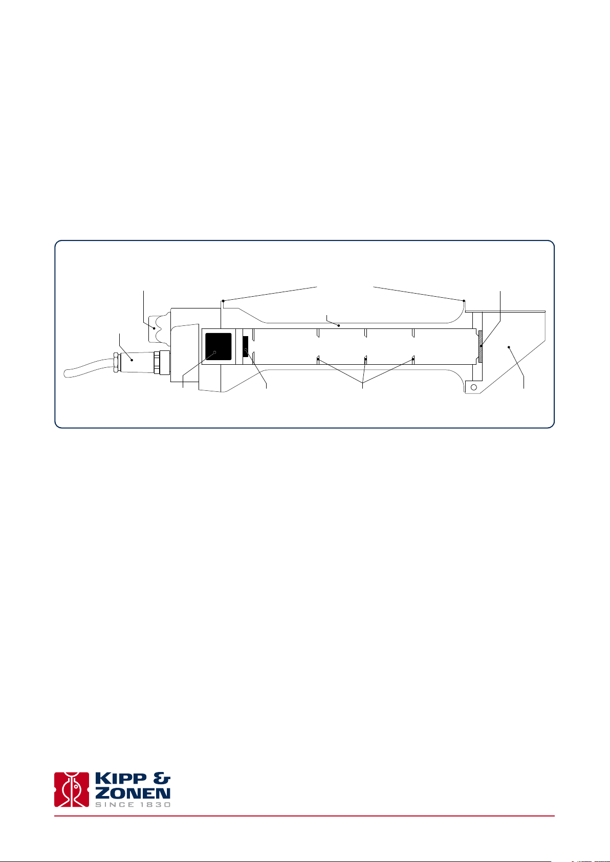
1.2 Key parts of the SHP1 pyrheliometer
drying cartridge quartz window
connector
smart interface
detector aperture rings rain shield
alignment aids
housing
Instruction Manual - SHP1 - Smart Pyrheliometer
10
Page 11
2. Installation
.
Please follow the instructions in this section carefully for the mechanical and electrical installation of the SHP1 pyrheliometer.
Do not turn on power to the instrument until instructed to do so.
Note Do not connect the instrument to a computer until instructed to do so.
Note Do not turn on power to the operating computer until instructed to do so.
2.1 Included with the product
Check the contents of the shipment for completeness (see below) and note whether any damage has occurred during transport. If
there is damage, a claim should be filed with the carrier immediately. In the case of damage and/or the contents are incomplete,
contact your local Kipp & Zonen representative or e-mail the Kipp & Zonen customer and product support department at:
support@kippzonen.com
Although a SHP1 pyheliometer is weather-proof and suitable for use in harsh environmental conditions, it has some delicate
mechanical parts. Please keep the original packaging for safe transport of the radiometer to the measurement site, or for use
when returning the radiometer for calibration.
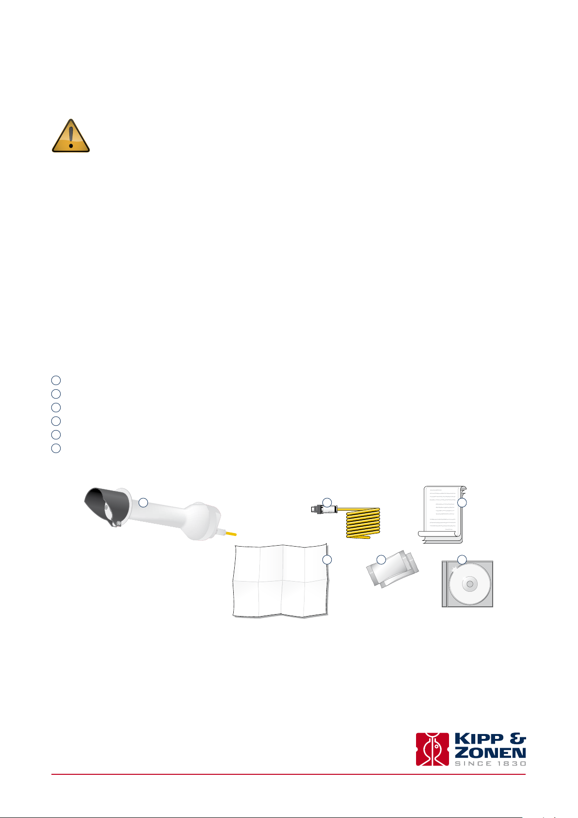
The following items are included with a SHP1 pyrheliometer:
1
Smart pyrheliometer and rain shield
2
Cable, pre-wired with 8-pins connector or connector only for customer cable
3
Calibration certificate
4
Instruction sheet
5
2 Dessicant bags
6
CD with product documentation and software
1
2
4
3
5
6
Instruction Manual - SHP1 - Smart Pyrheliometer
11
Page 12

2.2 Tools required
The tool required to mount a SHP1 on a SOLYS 2 or 2AP sun tracker is a 3 mm Allen key. Normally, the drying cartridge for the
SHP1 should be hand-tight, but a 16 mm or 5/8” open-ended wrench / spanner can be used to loosen it.
Check the condition of the desiccant in the SHP1 and replace before installation, if necessary; for example after a long storage
period.
The SHP1 instruction sheet plus the sun tracker manual contain all information to do the installation. When using the digital
output it might be convenient to set the Modbus® address prior to visiting the site, otherwise a computer and RS-485 / USB
converter may be required during installation.
2.3 Location and support
The following steps must be carefully taken for optimal performance of the instrument.
2.3.1 Location
Ideally, the site for the pyrheliometer plus sun tracker should be free from any obstructions to the hemispherical view from the
plane of the detector. If this is not possible, the site should be chosen in such a way that any obstruction over the azimuth range
between earliest sunrise and latest sunset should have an elevation not exceeding 5 ° (the apparent sun diameter is 0.5 °).
Further details for installation of the sun tracker can be found in the manual of the used tracker.
It is evident that the radiometer should be located in such a way that a shadow will not be cast upon it at any time (for example
by masts or ventilation ducts). Note that hot exhaust gas (> 100°C) will produce some radiation in the spectral range of the
radiometer and cause an oset in the measurements. This is important for an accurate measurement of the direct solar radiation.
The radiometer should be readily accessible for cleaning the front window and inspecting the desiccant.
2.3.2 Mounting
The mounting of the SHP1 pyrheliometer is related to the used sun tracker. Therefore we refer to the sun tracker manual for
further instructions on how to mount the SHP1 on the side mounting plate of the sun tracker.
2.3.3 Fitting the connector and cable
Locate the plug correctly in the radiometer socket, it only fits one way, and push it in. Screw the plug locking ring hand-tight.
Over-tightening may damage the waterproof seal. Secure the cable so that it cannot blow in the wind or cause a shadow on the
instrument.
Note The cable should be arranged with a curve below the instrument so that water drips o, rather than running along the
cable up to the connector.
Instruction Manual - SHP1 - Smart Pyrheliometer
12
Page 13
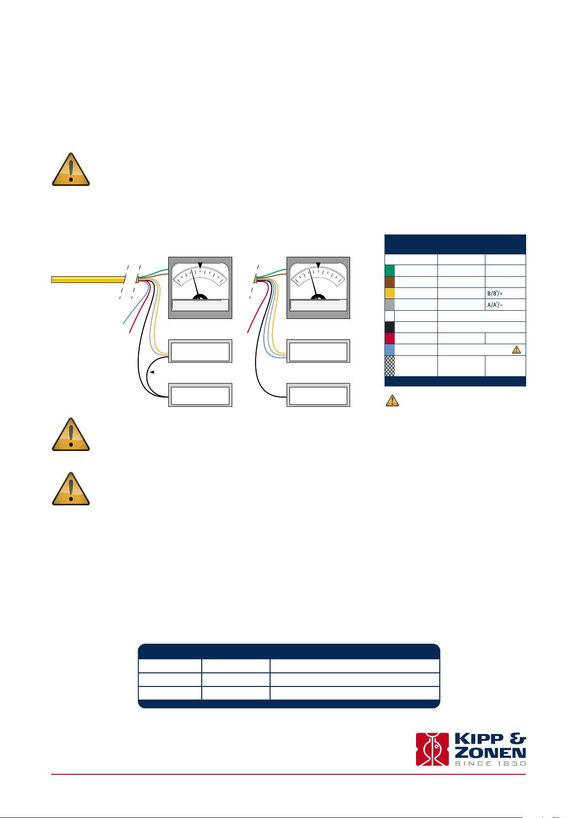
2.4 Electrical connections
As standard SHP1 pyrheliometers are supplied with a waterproof connector pre-wired to 10 m of high quality yellow cable with 8
wires and a shield covered with a black sleeve. Longer cables are available as options. The colour code of the wires and the
connector pin numbers are shown below and on the instruction sheet.
Special attention is needed to prevent power or ground loops when connecting the SHP1 to multiple readout devices.
Connecting the RS-485 to a grounded circuit and the analogue output to a floating circuit can cause unacceptable
ground loops. This may cause dierential voltages outside the SHP1 specifications and will damage the unit. We
recommend using either the analogue or the digital output but not both. The maximum dierential between either
of the Modbus® RS-485 lines (yellow and grey) and the power ground / RS-485 common line (black) is 70 VDC.
Radiometer connection
up to
serial number 144999
0.6
0.4
0.8
0.2
0.0
1.0
V / mA
SHP1-V or SHP1-A SHP1-V or SHP1-A
Modbus® RS-485
wire from power supply ground
to Modbus® ground needed
5 to 30 VDC
power supply
Radiometer connection
starting from
serial numbers 145000
0.6
0.4
0.8
0.2
0.0
1.0
V / mA
Modbus® RS-485
5 to 30 VDC
power supply
RADIOMETER CONNECTION
Wire Function Connect with
Green
3
Brown
6
Yellow
4
Grey
5
White
7
Black
8
Red
1
Blue
2
* Connect to ground if radiometer not grounded
The blue wire is not connect with radiometers
with serial number up to 144999
Analogue out V+/4-20 mA(+)
Analogue ground V
Modbus® RS-485
Modbus® RS-485
Power 5 to 30 VDC
Power ground / RS-485 Common
Modbus® common / Ground
HousingShield
-
/4-20 mA(-)
(12 V recommended)
Not connectedNone
Ground *
First connect all wires before plugging into the radiometer
The shield of the cable is connected to the aluminium radiometer housing through the connector body. The shield
at the cable end may be connected to ground at the readout equipment. Lightning can induce high voltages in the
shield but these will be led o at the pyrheliometer and data logger.
Note Long cables may be used, but the cable resistance must be smaller than 0.1% of the impedance of the readout
equipment for the analogue outputs and may aect the baud rate of the RS-485 digital connection.
2.5 Power connection
The minimum power supply voltage for a SHP1 pyrheliometer is 5 VDC. However, for optimal performance it is advised to use
12 VDC, especially when long cables are used. 5-volt power can only be used in combination with a short cable, maximum 10 m.
It is advised to protect the output of the power supply with a fast blowing fuse of maximum 250 mA rating.
Typical power consumption SHP1-V
5 VDC max. 50 mW (approx. 10.0 mA)
12 VDC max. 55 mW (approx. 4.5 mA)
24 VDC max. 60 mW (approx. 2.5 mA)
Instruction Manual - SHP1 - Smart Pyrheliometer
13
Page 14
.
Maximum power consumption and input current.
65 mW and 2 mA at the highest input voltage.
63 mW and 12.5 mA at the lowest input voltage.
The maximum inrush current is 200 mA.
Typical power consumption SHP1-A
5 VDC 77 mW (approx. 28 mA with 100 Ω load resistor)
12 VDC 83 mW (approx. 24 mA with 100 Ω load resistor)
24 VDC 100 mW (approx. 6 mA with 100 Ω load resistor)
The above mW values represent the dissipation within the SHP1-A. For the total power the energy in the load resistor has to
be added.
For supply voltages below 12 Volts or above 20 Volts it is advised to use a load resistor of less than 500 Ω to keep the power
consumption as low as possible.
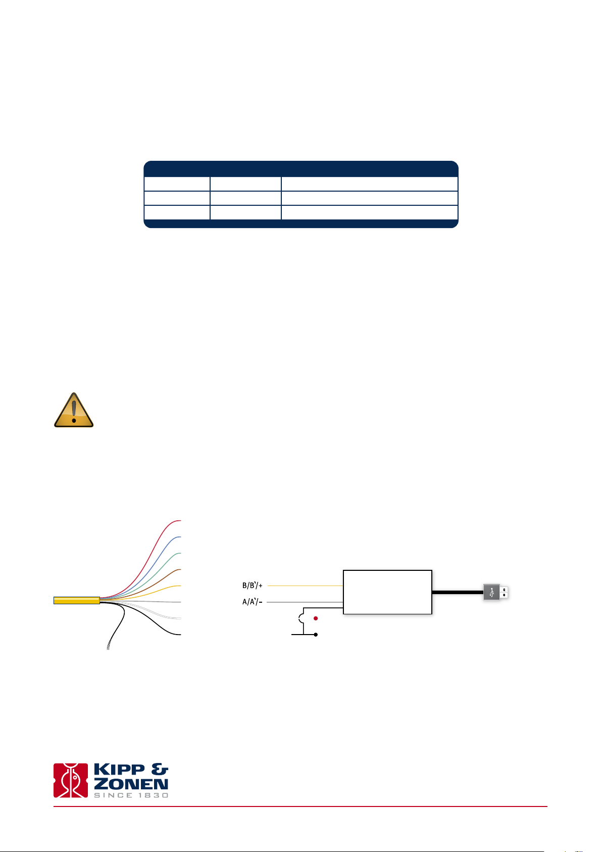
2.6 Data connection
Connection to a Personal Computer by Universal Serial Bus (USB)
The connection depends on the use of a RS-485 to USB converter.
The converter must have galvanic isolation between the inputs and outputs to prevent possible damage to the SHP1
digital interface. This is particularly an issue with portable computers (laptops, etc.) in which the power supplies
can generate large voltage spikes.
A suitable converter is the model USOPTL4 from B & B Electronics. One end has the USB connector to the PC the other end has
a connector with screw terminals for the instrument wires. This RS-485 converter is powered from the USB interface, so no
additional power adaptor is necessary.
Not connected
Not connected Situation up to serial number 144999
SHP1 connections to USB
.
Shield - ground connection
Analogue out +
Analogue out
Modbus® RS-485
Modbus® RS-485
Power 5 to 30 VDC
Power ground / RS-485 common
-
RS-485 / USB converter
Common
+ V
-
V
USB to PC
*
*Note Switches on the converter should be set for RS-485, 2-wire operation and Echo o.
Instruction Manual - SHP1 - Smart Pyrheliometer
14
Page 15
.
SHP1 connections to USB
Shield - ground connection
Not connected
Analogue out +
Analogue out
Modbus® RS-485
Modbus® RS-485
Modbus® common / Ground
Power 5 to 30 VDC
Power ground / RS-485 common
-
Situation from serial number 145000
RS-485 / USB converter
+ V
-
Common
V
*
*Note Switches on the converter should be set for RS-485, 2-wire operation and Echo o.
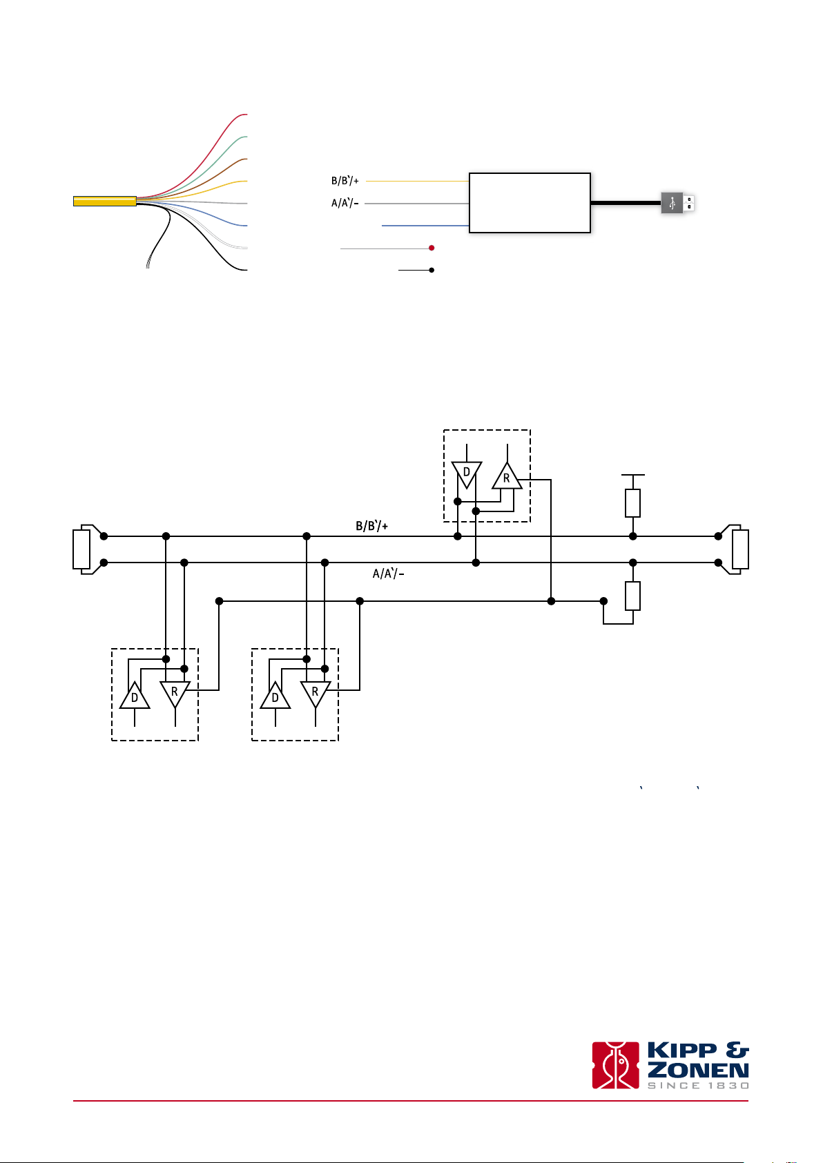
Connection to a RS-485 Network
The digital interface can be connected to a 2-wire RS-485 network as shown below.
Master
USB to PC
5 V
Pull up
LT LT
Balanced pair
Common
Pull down
Slave 1 Slave n
The interface needs also an external power to provide the voltage for the electronics. If the interface is the last device on the
network then a terminator consisting of a 120Ω or 150 Ω resistor has to be connected between terminal A/A'/- and B/B'/+. Never
place the line termination on the derivation cable. It is required to install the pull up and pull down resistors as shown in the
previous figure. The value of these resistors has to be within 650Ω and 850 Ω.
2.7 Analogue output connection
The SHP1-V (Volt version) has been factory set to an output of -200 to 2000 W/m². This applies only to the analogue output and
means that an output of 0 Volt corresponds to -200 W/m² (this will never be reached) and 1 Volt corresponds to 2000 W/m².
The digital output range can be modified with Modbus® commands. For the SHP1 the output range can be set to -200 to 4000 W/m²
for 0 to 1 Volt.
Instruction Manual - SHP1 - Smart Pyrheliometer
15
Page 16

The range has to start negative in order to show (small) negative readings also the analogue output itself cannot go negative. If
used in atmospheric conditions it is advised to keep the range as factory set.
The same applies for the SHP1-A (current version) that has been factory set to 0 to 1600 W/m² for 4 to 20 mA.
Here negative inputs will make the output go under 4 mA.
2.8 Calculations
2.8.1 Calculation 0 to 1 Volt version
The output is defined from 0 to 1 Volt representing -200 to 2000 W/m².
E
The irradiance value (
of the analogue output. For calculation of the solar irradiance (global or reflected) the following formula must be applied:
formula 1
E
= Solar radiation [W/m²]
solar
V = Output of radiometer [Volt]
2.8.2 Calculation 4 to 20 mA version
The output is defined from 4 to 20 mA representing 0 to 1600 W/m².
) can be simply calculated as shown below in formula 1. The formula assumes the factory default setting
solar
Negative outputs can cause the output to go slightly below 4 mA.
E
The irradiance value (
) can be simply calculated as shown below in formula 2. The formula assumes the factory default setting
solar
of the analogue output. For calculation of the solar irradiance (global or reflected) the following formula must be applied:
formula 2
E
= Solar radiation [W/m²]
solar
mA = Output of radiometer [mA]
2.8.3 Recommended cable types
Where cables need to be extended, or the customer prefers to provide their own cables, they should be suitable for outdoor used
and UV resistant.
Recommended types
RS-485 Ethernet CAT 5 shielded twisted pair (STP)
0 to 1 V Shielded 2-core signal cable
4 to 20 mA Shielded twisted pair control cable
Instruction Manual - SHP1 - Smart Pyrheliometer
16
Page 17

3. Accessories
.
Below is a brief description of the available cables for the SHP1 pyrheliometer.
3.1 Cables
For connection, a standard 10 m cable (8 wires) is supplied with a straight 8 pin connector on one side and loose ends on the
other side. Optional longer cables are available or just a loose connector to make your own cable / connection.
25 m cable with connector
50 m cable with connector
100 m cable with connector
Loose connector without cable
Instruction Manual - SHP1 - Smart Pyrheliometer
17
Page 18

Instruction Manual - SHP1 - Smart Pyrheliometer
18
Page 19

4. Software installation and configuration
.
The SHP1 pyrheliometer is delivered with a software programme SmartSensorDemo.exe, This software is supplied on a CD-ROM.
The operating computer must be running on a 32-bit or 64-bit version of Windows™ XP or Windows™ 7. Insert the CD into the
CD/DVD ROM drive of the operating computer and follow the on-screen installation instructions.
Note Before installing the software it is advised to disconnect all Modbus® devices except for the device that you wish
to configure.
The program is for testing the instrument and setting parameters. Basic data logging and display of data on a PC is also possible.
The software can handle up to 10 SHP pyrheliometers at the same time connected to the same RS-485 to USB converter. This
software is not intended for continuous long-term measurement, which should be done through the RS-485 network controller.
The setup depends on the used RS-485 adapter. An interface that could be used is from B&B, model USOPTL4, that has galvanic
isolation between in- and output. One side holds the USB connector to the PC the other side has a connector for connection of
the wires. This RS-485 adapter is powered from its USB interface.
A power supply for the SHP1 is required, this can be from a 5 to 30 Volt. 12 VDC is advised.
For set-up the following connection to a PC can be used. It is advised to use a RS-485 interface with galvanic isolation between
PC and RS-485.
Care has to be taken when connecting to an ungrounded (portable) PC, especially when also the analogue output is used. The
mains filter inside the PC can generate huge voltage peaks that can exceed the limits of the SHP1 pyrheliometer.
Not connected
Not connected Situation up to serial number 144999
SHP1 connections to USB
Shield - ground connection
SHP1 connections to USB
Shield - ground connection
Analogue out +
Analogue out
Modbus® RS-485
Modbus® RS-485
Power 5 to 30 VDC
Power ground / RS-485 common
Not connected
Analogue out +
Analogue out
Modbus® RS-485
Modbus® RS-485
Modbus® common / Ground
Power 5 to 30 VDC
Power ground / RS-485 common
-
-
RS-485 / USB converter
Common
+ V
-
V
Situation from serial number 145000
RS-485 / USB converter
Common
+ V
-
V
USB to PC
USB to PC
Instruction Manual - SHP1 - Smart Pyrheliometer
19
Page 20

4.1 Set up communication
When the Smart Sensor Demo program is opened there are 3 basic functions available; ‘Overview’, ‘Instrument’ and ‘Chart’.
With the ‘Overview’ tab active the communication parameters can be set as follows:
1. Select the communication port where the RS-485 converter is connected
2. Set the baud rate (19200 is the default setting)
3. Set the number of data bits and parity (8 bits with even parity is the default setting)
4. Set the sampling time (1 poll per second is the default setting)
5. Press the button ‘Discover the first connected device’ (or press ‘Discover all connected devices’ if there is more than one
device connected)
4.2 Change the Modbus® address
With the ‘Overview’ tab active, you have the possibility to change the Modbus® address.
The default Modbus® address of a SHP1 pyrheliometer is 1. Before you can use the instrument in your network you must reconfigure
the address to a unique number. Each Modbus® device connected to a network must have a unique address.
1. Enter the old Modbus® address, this can be found with the button ‘Discover all connected devices’ (for example, enter 1).
2. Enter the new Modbus® address. This must be a unique number (for example, 24).
3. Press the ‘Change Modbus address’ button.
When the address has been changed the SHP1 pyrheliometer will restart itself.
Instruction Manual - SHP1 - Smart Pyrheliometer
20
Page 21

4.3 Instrument data
With the ‘Instrument’ tab active the connected SHP1 pyrheliometer measurements are displayed. If multiple SHP1’s are connect-
ed the display will show alternating values from the dierent instruments. The large display showing the radiation can be
changed to (Body) Temperature.
The Body Temperature, SHP1 Power Supply Voltage and Time since power on are displayed in the lower part of the screen.
Instruction Manual - SHP1 - Smart Pyrheliometer
21
Page 22

4.4 Chart
With the Chart’ tab active the SHP1 pyrheliometer measurements can be displayed as a graph.
It will show the last 250 measurements of irradiance (‘Radiation’ in W/m²) and/or the pyrheliometer housing temperature
(‘Body Temp’ in °C), as an accumulating graph. Vertical scaling can be set to maximum or automatic.
Instruction Manual - SHP1 - Smart Pyrheliometer
22
Page 23

4.5 Data logging
Under File in Smart Sensor Demo the data logging can be set. The data format options are txt or csv. The csv log file has the
following format:
Together with the Modbus® address and the radiation data the body temperature and the power supply voltage to the SHP1
pyrheliometer are recorded.
At the bottom of the Smart Sensor Demo screen the message ‘The logfile C:\SHPdata\SHP-00.csv is open, press F12 to Append
Data.’ can be shown. With F12 a new data set can be linked to an existing file. Below is an example of a .txt file with linked data
from 2 days.
[11-1-2012 11:08:14]
DATE;TIME;SLAVE;SERIALNR;RADIANCE W/m²;TEMP C;POWER V
2012-01-11;11:08:15;001;00-0005; 708;30.7; 5.0;
2012-01-11;11:08:16;001;00-0005; 708;30.7; 5.0;
2012-01-11;11:08:17;001;00-0005; 708;30.7; 5.0;
[12-1-2012 9:20:17]
DATE;TIME;SLAVE;SERIALNR;RADIANCE W/m²;TEMP C;POWER V
2012-01-12;09:20:30;001;00-0005; 928;22.8; 5.0;
2012-01-12;09:20:37;001;00-0005; 929;22.8; 5.0;
2012-01-12;09:20:38;001;00-0005; 929;22.8; 5.0;
Instruction Manual - SHP1 - Smart Pyrheliometer
23
Page 24

Instruction Manual - SHP1 - Smart Pyrheliometer
24
Page 25

5. Operation and measurement
.
SHP1 pyrheliometers only require suitable sources of power and radiation (light) to operate and make measurements. However,
it is necessary to connect them to some sort of readout or data storage device in order to save the measurements, there is no
internal data memory.
5.1 Data collection
An optimal setting for the data interval is to sample every second and store one minute averages. For setting up the combination
of pyrheliometer and data storage please refer to the manual of the data collection device.
Take care when using the analogue output to match the output range of the pyrheliometer closely to the input range of the data
collection device to maximise the available resolution and minimise noise.
This can be done by determining the maximum expected analogue output of the pyrheliometer in your application and taking
the minimum input range of your data collection device that can just handle that signal.
5.2 Key parts of SHP1 pyrheliometer
The detector of the SHP1 is based on passive thermal sensing element called a thermopile. Although the detector construction
diers between models, the fundamental working principle is applicable to all radiometers.
The thermopile responds to the total energy absorbed by a unique black surface coating developed by Kipp & Zonen, which is
non-spectrally selective. The thermopile warms up and the heat generated flows through a thermal resistance to a heat-sink, the
pyrheliometer housing. The temperature dierence across the thermal resistance of the detector is converted into a small
voltage as a linear function of the absorbed irradiance.
A drying cartridge in the SHP1 pyrheliometer housing is filled with replaceable silica gel and prevents condensation on the inner
side of the window, which can cool down considerably on clear windless nights.
drying cartridge quartz window
connector
smart interface
detector aperture rings rain shield
alignment aids
housing
.
5.2.1 Window
The material of the pyrheliometer window defines the spectral measurement range of the instrument. In general 99% of the
solar radiation spectrum will be transmitted through the window and will be absorbed by the detector. The SHP1 window is
made of quartz.
Instruction Manual - SHP1 - Smart Pyrheliometer
25
Page 26

.
5.2.2 Detector
The thermopile sensing element is made up of a large number of thermocouple junction pairs connected electrically in series.
The absorption of thermal radiation by one of the thermocouple junctions, called the active (or ‘hot’) junction, increases its
temperature. The dierential temperature between the active junction and a reference (‘cold’) junction kept at a fixed temper-
ature produces an electromotive force directly proportional to the dierential temperature created.
This is a thermoelectric eect. The sensitivity of a pyrheliometer depends on the individual physical properties of the thermopile
and its construction. The sensitivity of each thermopile is unique and therefore each radiometer has an individual calibration
factor. This sensitivity is stored in the SHP1 pyrheliometer configuration memory.
The unique black coating on the top surface of the thermopile has a rough structure that eectively ‘traps’ more than 97% of the
incident radiation and heats up the hot junctions. The black-coated thermopile forms the detector, which has a spectral selectivity
of less than 2 %. This means that within the spectral range of the pyrheliometer, the absorption for each wavelength is equal to
within 2 %. The black absorptive coating is one of the most crucial and delicate parts of the pyrheliometer, Kipp & Zonen’s
provides the best possible stability over a long period of time under all meteorological circumstances.
5.2.3 Housing
The radiometer housing accommodates all the key parts of a SHP1 pyrheliometer. The anodized aluminium parts are lightweight
and give high mechanical and thermal stability to the instrument.
Due to fine mechanical construction SHP1 pyrheliometers are virtually sealed and comply with international standard IP 67.
5.2.4 Drying cartridge
To keep the detector and electronics dry and to prevent condensation forming inside the window with temperature changes a
self-indicating silica gel desiccant is used to absorb humidity within the pyrheliometer. When fresh the desiccant has an orange
colour. After some time absorbing moisture the colour will change to clear (transparent). At this time the silica gel is not fully
saturated, but should be replaced with fresh orange desiccant as soon as possible. Replacement desiccant is available through
Kipp & Zonen representatives.
5.2.5 Cable and connector
For ease of installation and replacement during re-calibration of the radiometer, the SHP1 is provided with a waterproof cable
socket fitted to the pyrheliometer housing. The matching waterproof plug is normally supplied pre-wired to a very high quality
yellow cable selected for low noise, very wide temperature range and UV resistance.
Cables come pre-wired to the connector plug in a range of lengths, 10 m is standard. 25 m, 50 m and 100 m lengths are also
available. The connector plug can also be supplied loose for the user to fit to their own cable.
Instruction Manual - SHP1 - Smart Pyrheliometer
26
Page 27

6. Maintenance and re-calibration
.
SHP1 pyrheliometers are simple to maintain and do not require any special tools or training. There are no service items requiring
scheduled replacement, only the desiccant of the SHP1 requires changing when needed, and a periodical check of the alignment
at the sun.
6.1 Daily maintenance
Once installed, the radiometer needs little maintenance. The front window must be cleaned and inspected regularly.
The frequency of cleaning is highly dependent upon the local weather and environmental conditions, such as dust, airborne
pollutants or salt spray in marine environments. Ideally, the window of the pyrheliometer should be cleaned every morning
before sunrise.
Note Clean the window using pure alcohol or distilled water and a lint-free cloth. Ensure that no smears or deposits are
left on the window.
6.2 Monthly maintenance
Check the desiccant in the drying cartridge. This is a self-indicating silica-gel. When it requires replacement the colour changes
from orange to clear.
To replace the desiccant unscrew the cartridge from the radiometer housing, if it is tight a 16 mm or 5/8" open-ended wrench /
spanner can be used to loosen it. Remove the cap from the end of the cartridge and safely dispose of the used silica-gel. Refill
with fresh desiccant, and refit the end cap to the cartridge. Make sure that the o-ring seal and its seat in the housing are clean,
grease with Vaseline if it is dry.
Note Screw in the drying cartridge hand-tight only, to avoid distorting the o-ring seal.
Desiccant refill packs are available from Kipp & Zonen. One pack is sucient for one complete refill.
6.3 Yearly maintenance
Check all the electrical connections. Unscrew the plugs, clean if necessary and then reconnect.
Check cables for damage caused by accident or by rodents.
Check the instrument mountings and any supports are secure.
6.4 Calibration
An ideal radiometer gives an output that is proportional to the absolute irradiance level. This relationship can be expressed as
a constant ratio called ‘sensitivity’. SHP1 pyrheliometers are very stable instruments, but they do change very slightly with time.
This is largely due to exposure of the black detector coating to UV solar radiation. Re-calibration is recommended every two
years. Normally this is carried out at the Kipp & Zonen factory or at an authorised calibration facility.
.
6.4.1 Calibration principle
At the Kipp & Zonen factory pyrheliometers are calibrated, or re-calibrated, in our laboratory according to ISO 9059:1990 ‘Solar
energy - Calibration of field pyrheliometers by comparison to a reference pyrheliometer’.
Kipp & Zonen uses a Xenon lamp with precise voltage stabilisation. The irradiance at the radiometers is approximately 800 W/m².
Instruction Manual - SHP1 - Smart Pyrheliometer
27
Page 28

The reference pyrheliometers are regularly calibrated outdoors at the World Radiation Centre (WRC) in Davos, Switzerland. The
spectral content of the laboratory calibration lamp diers from the outdoor solar spectrum at the World Radiation Centre. However,
this has no consequences for the transfer of calibration, because the reference and test radiometers have the same characteristics.
The sensitivity of the test pyrheliometer is calculated by comparison to the reference pyrheliometer readings and the calibration
certificate is produced. At Kipp & Zonen the complete process is automated under computer control, including programming the
SHP1 pyrheliometer with the correct calibration factors and default output range settings.
6.4.2 Calibration traceability to the WRR
Our reference pyrheliometers are calibrated at the World Radiation Centre (WRC) in Davos, Switzerland by comparison to the
World Radiometric Reference (WRR). They are also fully characterized for linearity, temperature dependence and directional
response to enable transfer of the sensitivity under the measurement conditions in Davos to our calibration laboratory conditions.
Kipp & Zonen keeps at least two reference instruments for each pyrheliometer model. These reference instruments are sent
alternate years to the WRC for calibration, so that production and calibration in Delft can carry on without interruption.
Kipp & Zonen calibration certificates include an overview of the calibration method, details of the reference pyrheliometer used,
traceability to the WRR, and the uncertainty in the full calibration chain from the WRR to the pyrheliometer being calibrated.
Instruction Manual - SHP1 - Smart Pyrheliometer
28
Page 29

7. Specifications
.
Kipp & Zonen reserves the right to make changes to specifications and other product documentation without prior notice.
7.1 Optical and electrical
Specifications SHP1
ISO 9060:1990 CLASSIFICATION
Response time (63 %) < 0.7 s
Response time
Zero offsets, temperature change (5 K/hr) < 1 W/m²
Non-stability (change/year)
Non-linearity (0 to 1000 W/m²)
Temperature dependence of sensitivity
Full viewing angle
Slope angle 1 °
Maximum irradiance 4000 W/m² (damage may occur above this level)
Operating temperature
Humidity
Spectral range
Required sun tracker accuracy
Weight 0.9 kg
(95 %)
(relative humidity) 0 to 100 % rH
(50 % points) 200 to 4000 nm
Other specifications
Analogue output
Analogue output range
Digital output
Digital output maximum range -400 to 4000 W/m²
Digital communication protocol Modbus®
Operating temperature
Ingress Protection
Supply voltage
Power consumption
Expected daily uncertainty < 1 %
Documentation
Recommended applications
(1)
The analogue output range of SHP1 can be rescaled by the user to a maximum of -200 to 4000 W/m²
SHP1 pyrheliometer has a standard cable length of 10 m. Optional cable lengths 25 m, 50 m and 100 m
Note: The performance specifications quoted are worst-case and/or maximum values
(IP) 67
(at 12 VDC)
First Class
< 2 s
< 0.5 %
< 0.2 %
< 1 %
(-40 °C to +70 °C)
< 0.5 %
(-30 °C to +60 °C)
(±0.2)
5 °
(±0.2)
-40 °C to +80 °C
< 0.5° from ideal
-V version: 0 to 1 V
-A version: 4 to 20 mA
-V version: -200 to 2000 W/m²
-A version: 0 to 1600 W/m²
2-wire RS-485
-40 °C to +80 °C
5 to 30 VDC
-V version: 55 mW
-A version: 100 mW
Calibration certificate traceable to WRR, multi-language instruction sheet, manual and software on CD-ROM
High performance direct radiation monitoring for meteorological stations or concentrated solar energy applications
(1)
7.2 Dimensions
195.6 mm
Ø38 mm
322 mm
Instruction Manual - SHP1 - Smart Pyrheliometer
29
Page 30

Instruction Manual - SHP1 - Smart Pyrheliometer
30
Page 31

8. Trouble shooting
.
There are no user-serviceable parts within the SHP1 pyrheliometer and it must not be opened without the agreement and instruction
of Kipp & Zonen.
8.1 Output signal not present or incorrect
The following contains a procedure for checking the instrument in case it appears that it does not function correctly:
1. Check the SHP1 pyrheliometer cable wires are properly connected to the readout equipment.
2. Check the power supply (12 VDC recommended).
3. Check that the instrument has a unique Modbus® address.
4. Compare the digital and analogue outputs to see if the problem is in one output only.
5. Check the instrument location. Are there any obstructions that cast a shadow on the instrument by blocking the direct sun
during some part of the day?
6. Check the window, it should be clear and clean. If condensation is deposited on the inside, please change the desiccant. If too
much water is deposited internally the drying cartridge should be removed and the instrument warmed to dry it and then
replace with new desiccant. It may take several days for the sensitivity to fully recover to the original value.
7. For analogue outputs check the data logger or integrator input oset such that a signal of 0 Volt or 4 mA (as appropriate)
gives a ‘zero’ reading.
8. If water, frost or ice is deposited on the window, clean it. Probably water droplets will evaporate in less than one hour under
sunlight.
Any malfunction or visible damage should be reported to your Kipp & Zonen representative, who will suggest the appropriate action.
8.2 Frequently Asked Questions
The most frequently asked questions are listed below. For an update or further information refer to our website at www.kippzonen.com
Q: Is it possible that direct radiation is higher than global radiation?
A: Yes, this is possible because the relation is:
Global = Diuse + (Direct x cos α); α is the solar zenith angle
So with low solar elevation (small cos α) the contribution of the direct radiation to the total (global) is relatively small.
Q: When is the pyrheliometer properly aligned?
A: When the second alignment aid on top of the SHP1 is in the light spot falling through the first alignment aid the pyrheliometer
is properly aligned. As long as the second alignment aid is in the light spot, the SHP1 is within specifications.
Q: Is the pyrheliometer calibration affected by the length of the signal cable?
A: With longer cable lengths the impedance increases, however it does not aect the radiometer sensitivity for the following
reason. For the SHP1-V the impedance of the voltage measurement device is at least 1000 times more than the impedance of the
pyrheliometer plus cable. Therefore the current that goes through the readout cable is negligible and won’t generate an oset.
For the SHP1-A current versions the cable length is limited by the power supply voltage and voltage drop over the cable. However
the low cable impedance (80 Ω/km) and normally high impedance of the read-out unit / logger is normally no limitation.
The digital RS-485 output can operate over cable lengths up to 1000 m, depending on the baud-rate used.
Instruction Manual - SHP1 - Smart Pyrheliometer
31
Page 32

Instruction Manual - SHP1 - Smart Pyrheliometer
32
Page 33

9. Customer support
.
If you require any support for your Kipp & Zonen product please contact your local representative in the first instance. The
information can be found in the ‘Contact’ section (home tab) of our website at www.kippzonen.com
Alternatively, you can contact us directly at www.kippzonen.com/support
Please include the following information:
• Instrument model
• Instrument serial number
• Details of the fault or problem
• Examples of data files
• Readout device, data acquisition system and operating system
• Interfaces and power supplies
• History of any previous repairs or modifications
• Pictures of the installation
• Overview of the local environment conditions
Kipp & Zonen guarantees that your information will not be shared with other organisations.
Instruction Manual - SHP1 - Smart Pyrheliometer
33
Page 34

Instruction Manual - SHP1 - Smart Pyrheliometer
34
Page 35

10. Keyword index
.
Term Explanation
Albedo The portion of incoming radiation which is reflected by a surface
Azimuth angle Angle in horizontal direction (0 to 360 °) normally referred to North
Angle of incidence Incident angle from zenith (0° is vertical, 90° is horizontal)
Cosine response Radiometer directional response according to the cosine law
Diuse horizontal irradiance Solar radiation, scattered by water vapour, dust and other particles as it passes through
the atmosphere falling on a horizontal surface (DHI)
Direct normal irradiance Radiation that has travelled in a straight path from the sun falling on a surface normal to
the beam (DNI)
Global horizontal irradiance Total irradiance falling on a horizontal surface (GHI)
Global = Diuse + (Direct x cos α); α is the solar zenith angle
Irradiance Radiant flux density (W/m²)
Long-wave radiation Radiation with wavelengths from 4 m to more than 40 m
Pyranometer Radiometer for measuring short-wave global radiation
Pyrgeometer Radiometer for measuring long-wave radiation
Pyrheliometer Radiometer for measuring direct short-wave radiation
Short-wave radiation Radiation with wavelengths from approximately 300 nm to 4000 nm (4 m)
Thermopile Thermal detector made up of many thermocouple junctions
WMO World Meteorological Organisation, Geneva, Switzerland
WRC World Radiation Centre, Davos, Switzerland
WRR World Radiometric Reference (standard radiation scale) at WRC
WSG World Standard Group of radiometer at WRC
Zenith angle Angle from zenith (0 ° is vertical)
Instruction Manual - SHP1 - Smart Pyrheliometer
35
Page 36

Instruction Manual - SHP1 - Smart Pyrheliometer
36
Page 37

Appendices
A. Modbus®
A.1 Modbus® commands
The commands are all according to the Modbus® RTU protocols described in the document: ‘Modbus® over serial line V1.02’ and
‘Modbus® application protocol V1.1b’ available from the Modbus® organization (www.modbus.org). The commands can be tested
using software tools, such as the program ‘Modbus® Poll’ from www.modbustools.com.
The following commands are implemented:
Function Sub function Description
0x01 N/A Read Coils
0x02 N/A Read Discrete Inputs
0x03 N/A Read Holding Registers
0x04 N/A Read Input Register
0x05 N/A Write Single Coil
0x06 N/A Write Holding Register
0x10 N/A Write multiple Registers
The SHP1 does not make a dierence between a ‘coil’ and a discrete input. The only dierence is that a discrete input is read only.
The SHP1 does not make a dierence between a holding register and an input register. The only dierence is that an input
register is read only.
A.2 Input registers
Input registers are read only
Real-time Processed Data
Register Parameter R/W Type Mode Description
0 IO_DEVICE_TYPE R U16 All Device type of the sensor
1 IO_DATAMODEL_VERSION R U16 All Version of the object data model 100=this version
2 IO_OPERATIONAL_MODE R U16 All Operational mode: Normal, Service, Calibration and so on
3 IO_STATUS_FLAGS R U16 All Device status flags
4 IO_SCALE_FACTOR R S16 All Range and scale factor sensor data
5 IO_SENSOR1_DATA R S16 N,S Temperature compensated data sensor 1 in W/m²
6 IO_RAW_SENSOR1_DATA R S16 N,S Sensor data sensor 1 in W/m²
7 IO_STDEV_SENSOR1 R S16 N,S Standard deviation sensor 1 in 0.1 W/m²
8 IO_BODY_TEMPERATURE R S16 N,S Body temperature in 0.1 °C
9 IO_EXT_POWER_SENSOR R S16 N,S External power voltage in 0.1 V
10 to 15 FACTORY USE ONLY
16 IO_DAC_OUTPUT_VOLTAGE R U16 N,S DAC output voltage (actual voltage)
17 IO_SELECTED_DAC_INPUT R U16 N,S DAC selected input data
(1)
The scale factor defines the format and number of decimal places
(1)
Instruction Manual - SHP1 - Smart Pyrheliometer
37
Page 38

Real-time Data A/D Counts
Register Parameter R/W Type Mode Description
18 IO_ADC1_COUNTS R S32 All Input voltage sensor 1 in 0.01 V
19 (R18=MSB, R19=LSB)
20 IO_ADC2_COUNTS R S32 All Not supported, always 0
21
22 IO_ADC3_COUNTS R S32 All Input voltage body temperature sensor in 0.01 V
23 (R22=MSB, R23=LSB )
24 IO_ADC4_COUNTS R S32 All Input voltage power sensor in 0.01 V
25 (R24=MSB, R25=LSB)
Error reports
Register Parameter R/W
26 IO_ERROR_CODE R U16 All Most recent/ actual error code
27 IO_PROTOCOL_ERROR R U16 All Protocol error/communication error
28 IO_ERROR_COUNT_PRIO1 R U16 All Error code priority 1
29 IO_ERROR_COUNT_PRIO2 R U16 All Error count priority 2
30 IO_RESTART_COUNT R U16 All Number of controlled restarts
31 IO_FALSE_START_COUNT R U16 All Number of uncontrolled restarts
32 IO_SENSOR_ON_TIME R U16 All On time in seconds (MSB word)
33 IO_SENSOR_ON_TIMEL R U16 All On time in seconds (LSB word)
41 IO_BATCH_NUMBER R U16 All Production batch number
42 IO_SERIAL_NUMBER R U16 All Serial number
43 IO_SOFTWARE_VERSION R U16 All Software version
44 IO_HARDWARE_VERSION R U16 All Hardware version
45 IO_NODE_ID R U16 All (MODBUS®/SMA) device address RS-485
(2)
Writing any value to input registers 26-33 will reset the contents of the registers
(2)
Type Mode Description
Legend
Register Modbus® register Modbus® register 0 is the first register.
Parameter Name Name of the register
R/W Read write R Read only
R/W Read/write
Type Type and size U16 16 bit unsigned integer
S16 16 bit signed integer
S32 32 bit signed integer (MSB first, LSB last)
Mode Operation mode N available in normal mode
S available in service mode
C available in calibration mode (not for users)
F available in factory mode (not for users)
All available in all modes
Instruction Manual - SHP1 - Smart Pyrheliometer
38
Page 39

.
A.3 Holding registers
Device Control
Register Parameter R/W Type Mode Description
34 IO_DEF_SCALE_FACTOR R/W S16 All Default scale factor
35 to 40 Factory use only
A.4 Read input register
Many of the registers and controls are for remote diagnostics. In this chapter only the most interesting registers and controls
are described.
Register 0 IO_DEVICE_TYPE
The device typed defines which device is connected. The default values are:
Instrument type Sensor type Device type
SMP3-V 1 601
SMP3-A 1 602
SMP11-V 3 603
SMP11-A 3 604
SHP1-V 6 613
SHP1-A 6 614
This register can be used to check the type of the connected device.
Register 1 IO_DATAMODEL_VERSION
The data-model describes the functions supported by the smart sensor. This document is valid for data-model version: ‘100’ and
‘101’. A dierent implementation of the Modbus® protocol (with new features) could result in a dierent data model ‘that is’ or
‘that is not’ compatible with the older version.
The value of this register must be ‘100’ or ‘101’. If you receive another value then you should read an updated version of this
document and check the dierences.
Register 2 IO_OPERATIONAL_MODE
The operation mode defines the state of the smart sensor. The operational modes are 1 = Normal Mode, 2 = Service Mode,
3 = Calibration Mode, 4 = Factory Mode and 5 = Error mode. The standby mode (mode 0) is not supported.
After power on the operation mode (1) is set. When the IO_CLEAR_ERROR is set then the smart sensor always returns to the
normal mode. When the Error mode (5) is set, then there is a fatal error.
Instruction Manual - SHP1 - Smart Pyrheliometer
39
Page 40

.
Register 3 IO_STATUS_FLAGS
This register defines the status of the smart sensor and the validity of the data. Each bit has a special meaning. Bit 0 is the first
(least significant) bit.
Bit 0 Quality of the signal see IO_VOID_DATA_FLAG
Bit 1 Overflow see IO_OVERFLOW_ERROR
Bit 2 Underflow see IO_UNDERFLOW_ERROR
Bit 3 Error flag see IO_ERROR_FLAG
Bit 4 ADC Error see IO_ADC_ERROR
Bit 5 DAC Error see IO_DAC_ERROR
Bit 6 Calibration Error see IO_CALIBRATION_ERROR
Bit 7 Update EEPROM error see IO_UPDATE_FAILED
Register 4 IO_SCALE_FACTOR
The scale factor defines the number of fractional digits, the range and the position of the decimal point for the following
registers: IO_SENSOR1_DATA, IO_SENSOR2_DATA, IO_RAW_SENSOR1_DATA and IO_RAW_SENSOR2_DATA. The scale factor is read
only. The default value of the scale factor is set during calibration mode or it can be changed during operation (see register
IO_DEF_SCALE_FACTOR and coil IO_AUTO_RANGE).
If the register IO_SCALE_FACTOR is not set to 0 then you must multiply or divide the data of register (X), whereas X is one of the
above mentioned registers.
Scale factor = 2 (floating point) result = (integer) register (X) / 100.0
Scale factor = 1 (floating point) result = (integer) register(X) / 10.0
Scale factor = 0 (floating point) result = (integer) register(X)
Scale factor = -1 (floating point) result = (integer) register(X) * 10.0
The default value of register IO_SCALE_FACTOR is 0. However, this value can be set to a dierent value if the coil IO_AU-
TO_RANGE is set or a dierent value is written to the register IO_DEF_SCALE_FACTOR (set default scale factor).
Register 5 IO_SENSOR1_DATA
This register holds the actual data (solar radiation) measured by the sensor. The solar radiation is measured in W/m².
If the register IO_SCALE_FACTOR is not set to 0 then you must multiply or divide the data as described under register 4.
The raw data from the sensor is calibrated, linearized; temperature compensated and filtered using 2 dierent kinds of filters
(See IO_FAST_RESPONSE and IO_TRACKING_FILTER).
Register 6 IO_RAW_SENSOR1_DATA
The raw sensor data is calibrated but not linearized and temperature compensated. If the register IO_SCALE_FACTOR is not set
to 0 then you must multiply or divide the data as described under register 4, IO_SCALE_FACTOR.
Instruction Manual - SHP1 - Smart Pyrheliometer
40
Page 41

.
Register 7 IO_STDEV_SENSOR1
This register is used to calculate the standard deviation over the signal. When the register is read the data is sent to the computer
and at the same time a new calculation is started. The next time register 7 is read the standard deviation over the last period is
sent to the computer and a new calculation is started. If the poll frequency is quite high (for example 1 poll per second) then the
standard deviation will be zero or almost zero, but if the poll frequency is very low then the standard deviation can be quite high,
indicating that the data in register 5 or 6 changed dramatically since the last poll. The standard deviation is measured in 0.1 W/m².
To convert the data to a floating point, make the following calculation:
(floating point) result = (integer) register (IO_STDEV_SENSOR1) / 10.0
Register 8 IO_BODY_TEMPERATURE
The body temperature sensor measures the temperature of the body in 0.1°C.
The convert the data to a floating point number, make the following calculation:
(floating point) result = (integer) register (IO_BODY_TEMPERATURE) / 10.0
Register 9 IO_EXT_POWER_SENSOR
The Ext power sensor measured the external voltage applied to the sensor in 0.1 Volt.
The convert the data to a floating point number, make the following calculation:
(floating point) result = (integer) register (IO_EXT_POWER_SENSOR) / 10.0
Example
Read registers: ‘operational mode to external power’ from Modbus® device with address 1.
Tx transmitted data to the smart sensor
Rx received data from the smart sensor
SendModbusRequest (0x04, 1, IO_OPERATIONAL_MODE, 8);
Tx 01 04 00 02 00 08 50 0C
Rx 01 04 10 00 01 00 00 00 00 03 E5 03 E5 00 00 00 F8 00 EA 66 12
Explanation of the received bytes:
01 = Modbus® address
04 = read input registers
10 = number of received data bytes
00 01 = operational mode (mode 1)
00 00 = status flags (none)
00 00 = scale factor = 0 = 1x
03 E5 = 997 decimal = sensor 1 data in W/m²
03 E5 = 997 decimal = raw sensor 1 data in W/m²
00 00 = 0 = standard deviation sensor 1
00 F8 = 248 = 24.8 °C.
00 EA = 234 = 23.4 Volt
66 12 = Modbus® checksum (CRC16)
Instruction Manual - SHP1 - Smart Pyrheliometer
41
Page 42

.
A.5 Discrete inputs
A discrete input can be true or false. A discrete input is read only; a coil can be read or written.
Status indicators
Input Parameter R/W Def. Mode Description
0 IO_FALSE R 0 All Always false (for testing only)
1 IO_TRUE R 1 All Always true (for testing only)
2 IO_VOID_DATA_FLAG R * All Void signal, 1=unstable signal, temperature too low or too high
3 IO_OVERFLOW_ERROR R * All Overflow, signal out of range
4 IO_UNDEFLOW_ERROR R * All Underflow signal out of range
5 IO_ERROR_FLAG R * All General hardware error (set if one of the H/W error flags is set)
6 IO_ADC_ERROR R * All Hardware error A/D converter
7 IO_DAC_ERROR R * All Hardware error D/A converter
8 IO_CALIBRATION_ERROR R * All Calibration checksum error
9 IO_UPDATE_FAILED R * All Update calibration parameters failed
Legend
Input Discrete input Modbus® discrete input 0 is the first discrete input
Coil Modbus® Coil A coil can be read or written.
Parameter Name Name of the register
R/W Read write R Read only
R/W Read/write
Def Default value default value at power on (0, 1or *) * = undefined
Mode operation mode N available in normal mode
S available in service mode
C available in calibration mode (not for users)
F available in factory mode (not for users)
All available in all modes
Inputs can be read in all modes but some coils can’t be written in normal mode or service mode.
A.6 Coils
Device control
Coil Parameter R/W Def. Mode Description
10 IO_CLEAR_ERROR R/W 0 All Select normal operation and clear error (1=clear error)
11 to 17 FACTORY USE ONLY
18 IO_RESTART_MODBUS R/W 0 All Restart the device with modbus® protocol
19 FACTORY USE ONLY
20 IO_ROUNDOFF R/W 1 S,N Enable rounding of sensor data
21 IO_AUTO_RANGE R/W 0 S,N Enable auto range mode (0=no auto range)
22 IO_FASTRESPONSE R/W 0 S,N Enable fast response filter (0=no filter)
23 IO_TRACKING_FILTER R/W 1 S,N Enable tracking filter (0=no filter)
Note The default values of the device options are stored in non-volatile memory. The default values can be overruled during
operation. However, at power-on the default values are restored and the smart sensor will start up with the default
values stored in the non-volatile memory.
Instruction Manual - SHP1 - Smart Pyrheliometer
42
Page 43

.
ADC CONTROL
Coil Parameter R/W Def. Mode Description
24 to 34 Factory use only
A.7 Read write holding registers
Register 34 IO_DEF_SCALE_FACTOR
The default scale factor is set in the factory mode or service mode and is stored in non-volatile memory. The default scale factor
stored in non-volatile memory is always set after a power-on. However it is possible to change the default setting during opera-
tion by writing a value to the register 34.
Note This value is not stored in non-volatile memory and is overwritten with the default value at power on.
The following values are valid:
Scale factor = 2
Scale factor = 1
Scale factor = 0
Scale factor = -1
Scale factor 0 is the default value. See also input register 4 IO_SCALE_FACTOR.
A.8 Read discrete inputs
Discrete input 0 IO_FALSE This discrete input is always false
Discrete input 1 IO_TRUE This discrete input is always true
Discrete input 2 IO_VOID_DATA_FLAG
The void data flag is raised when the data in register IO_SENSOR1_DATA or IO_RAW_SENSOR1_DATA is not valid, because the
body temperature of the sensor is too low or too high, when there is an internal overflow condition, because a calculation is out
of range or a division by zero occurred, the reference voltage of the ADC is not stable or the digital filter is not stable. When the
IO_VOID_DATA_FLAG is set, bit 0 in the IO_STATUS_FLAGS is also set.
The IO_VOID_DATA_FLAG and bit 0 of the IO_STATUS_FLAGS are cleared when the IO_VOID_DATA_FLAG is read by the computer.
Discrete input 3 IO_OVERFLOW_ERROR
This discrete input is raised when an out of range condition occurs and the sensor data (see IO_SENSOR1_DATA) is above the
maximum value specified by the calibration program or above 29,999. The typical maximum value is 4000 W/m².
When the IO_OVERFLOW_ERROR is set, bit 1 in the IO_STATUS_FLAGS is also set.
The IO_OVERFLOW_ERROR and bit 1 of the IO_STATUS_FLAGS are cleared when the IO_OVERFLOW_ERROR is read by the computer.
Discrete input 4 IO_UNDERFLOW_ERROR
This discrete input is raised when an underflow condition occurs and the sensor data (see IO_SENSOR1_DATA) is below the
minimum value specified by the calibration program or below -29,999. The typical minimum value is -400 W/m².
When the IO_UNDERFLOW_ERROR is set, bit 2 in the IO_STATUS_FLAGS is also set.
The IO_UNDERFLOW_ERROR and bit 2 of the IO_STATUS_FLAGS are cleared when the IO_UNDERFLOW_ERROR is read by the
computer.
Instruction Manual - SHP1 - Smart Pyrheliometer
43
Page 44

.
Discrete input 5 IO_ERROR_FLAG
The error flag is raised when there is a (fatal or correctable) hardware error or software error such as: ADC error, DAC error,
calibration error or when the update of the calibration data failed. When the IO_ERROR_FLAG is raised the error code is copied
to the register IO_ERROR_CODE (see register 26).
The error flag is cleared when a true condition is written to the coil: ‘IO_CLEAR_ERROR’. This has no eect when the error is fatal
or not resolvable such as a calibration error.
The error flag is always set after a power up, this is to indicate the power went o, or a restart occurred. The computer should
raise the IO_CLEAR_ERROR in order to reset the error flag.
Discrete input 6 IO_ADC_ERROR
This flag is raised when the A/D converter responsible for the conversion of the analogue signals to digital signals detected a
failure (hard or software).
The ADC error flag is cleared when a true condition is written to the coil: ‘IO_CLEAR_ERROR’ and the error produced by the ADC,
is not fatal.
Discrete input 7 IO_DAC_ERROR
This flag is raised when the D/A converter responsible for the conversion of the digital signal to the analogue output signal
detected a failure (hard or software).
The DAC error flag is cleared when a true condition is written to the coil: ‘IO_CLEAR_ERROR’ and the error produced by the DAC,
is not fatal.
Discrete input 8 IO_CALIBRATION_ERROR
The calibration error flag is raised when the sensor was not calibrated or a checksum error was detected in the calibration data.
This flag can’t be cleared unless the sensor is sent back to the manufacturer or dealer for a re-calibration.
Discrete input 9 IO_UPDATE_FAILED
The update failed is raised when data is written to the non-volatile memory and the update failed. This can happen in calibration
mode when calibration data in written to non-volatile memory or in the service mode when device options are written to the
non-volatile memory.
If this error is set you should retry the last update action. If the error does not disappear then there could be a hardware
problem with the non-volatile memory (EEPROM).
A.9 Read write discrete coils
Coil 10 IO_CLEAR_ERROR
Setting this coil will clear the error only when the error is a non-fatal error. Reading this coil will always return a 0. The coil
IO_CLEAR_ERROR can be used to select the normal mode (see IO_OPERATIONAL_MODE).
The smart sensors will always start-up in the normal mode.
Note Use IO_CLEAR_ERROR to return to the normal mode.
Instruction Manual - SHP1 - Smart Pyrheliometer
44
Page 45

.
Coil 20 IO_ROUNDOFF
Setting this coil enables rounding of the data presented in IO_SENSOR1_DATA and IO_RAW_SENSOR1_DATA.
If not set then the customer should round o the received data before processing the data.
The default value after power on is ON.
If IO_ROUNDOFF is cleared, then the sensor is not calibrated and could produce more digits, than there are significant digits.
Coil 21 IO_AUTO_RANGE
Setting this coil enables the auto-range feature. The auto-range feature increases the number of digits for small signals
The default value after power on is OFF.
If IO_AUTO_RANGE is set then the sensor is not calibrated and could produce more digits, than there are significant digits.
Coil 22 IO_FASTRESPONSE
Setting this coil enables the fast response filter. This filter increases the step response of the sensor. Disabling the fast response
give the SHP1 pyrheliometers the same response time as the CMP equivalents.
The default value after power on is ON.
Coil 23 IO_TRACKING_FILTER
Setting to this coil enables the tracking filter. The tracking filter reduces the noise of the signal. However, when the filter is on,
the step response on a sudden signal change is decreased. The smart sensor uses variable filter constants to minimize the eect
on the step response.
The default value after power on is OFF.
A.10 Requesting serial number
Register 41 IO_BATCH_NUMBER
The batch number defines the production year of the smart sensor, 11 = 2011, 12=2012 etc.
Register 42 IO_SERIAL_NUMBER
Register 42 defines the 4 digits serial number of the smart sensor. Only the combination of the batch number and serial number
is unique.
A.11 Simple demonstration program
The simple ‘C’ program below will show how to read the sensor data and how to deal with errors. The program will read the
registers: ‘operational mode, status flags, scale factor, and sensor data’ from Modbus® device with address 2 into registers
uOperationMode, uStatusFlags, iScaleFactor and iSensorData. Then the program will check the operation mode (must be
‘normal’) and if there are no errors flags set in iStatusFlags. If there is an error then set the IO_ERROR_FLAG.
Instruction Manual - SHP1 - Smart Pyrheliometer
45
Page 46

.
UInt16 uOperationalMode = 0;
UInt16 uStatusFlags = 0;
Int16 iScaleFactor = 0;
Int16 iSensorData = 0;
float fSensorData = 0;
int main (void)
{
while (true)
{
// Send Modbus® request 0x04 Read input registers to slave 2
// Get modus data will wait for the answer and copies the data to registers
// uOperationalMode, uStatusFlags, iScaleFactor and iSensorData
SendModbusRequest (0x04, 2, IO_OPERATIONAL_MODE, 4);
WaitModbusReply ();
GetModbusData ();
If (uOperationalMode != 1)
{
// Send Modbus® request 0x05 write single coil to slave 2
SendModbusRequest (0x05, 2, IO_CLEAR_ERRROR, true);
WaitModbusReply ();
}
else if (uStatusFlags != 0)
{
SendModbusRequest (0x05, 2, IO_CLEAR_ERRROR, true);
WaitModbusReply ();
}
switch (iScaleFactor)
{
case 2: fSensorData = (float)(iSensorData) / 100.0;
case 1: fSensorData = (float)(iSensorData) / 10.0;
case 0: fSensorData = (float)(iSensorData);
case -1: fSensorData = (float)(iSensorData) * 10.0;
default: fSensorData = 0.0;
}
// wait 1 second
Delay (1000);
}
}
Instruction Manual - SHP1 - Smart Pyrheliometer
46
Page 47

B. Pyrheliometer physical properties
B.1 Spectral range
The spectrum of the solar radiation reaching the Earth’s surface is in the wavelength range between 280 nm and 4000 nm,
extending from ultraviolet (UV) to the far infrared (FIR). Due to the excellent physical properties of the quartz window and black
absorber paint, Kipp & Zonen SHP1 pyrheliometers are equally sensitive in a wide spectral range. 99% of the total energy will
be absorbed by the thermal detector.
1.0
0.5
Response [arbitrary units]
0
Wavelength [nm]
B.2 Sensitivity
For the SHP1 pyrheliometers the physical sensitivities are converted to a digital output that is identical for all sensors. The
SHP1-V has an analogue output of 0 to 1 Volt for -200 to 2000 W/m². The SHP1-A output is 4 to 20 mA for 0 to 1600 W/m².
3002001000
400 500 1000 2000 3000 4000
Solar radiation spectrum at sea level
Spectral response of SHP1 pyrheliometer
B.3 Response time
Any measuring device requires a certain time to react to a change in the parameter being measured. The radiometer requires time
to respond to changes in the incident radiation. The response time is normally quoted as the time for the output to reach 95%
(sometimes 1/e, 63%) of the final value following a step-change in irradiance. It is determined by the physical properties of the
thermopile and the radiometer construction. SHP1 pyrheliometer is set to digitally accelerate the physical response.
B.4 Non-linearity
The non-linearity of a pyrheliometer is the percentage deviation in the sensitivity over an irradiance range from 0 to 1000 W/m²
compared to the sensitivity calibration irradiance of 500 W/m². The non-linear eect is due to convective and radiative heat
losses at the black absorber surface which make the conditional thermal equilibrium of the radiometer non-linear.
B.5 Tempearture dependence
The sensitivity change of the radiometer with ambient temperature change is related to the thermo-dynamics of the radiometer
construction. The temperature dependence is given as percentage deviation with respect to the calibrated sensitivity at +20°C.
The SHP1 pyrheliometer has an integrated temperature sensor and use a fourth-order polynomial function to actively correct for
temperature errors over a -40 °C to +70 °C range.
B.6 Operating temperature
The operating temperature range of the radiometer is determined by the physical properties of the individual parts. Within the specified
temperature range Kipp & Zonen radiometers can be operated safely. Outside this temperature range special precautions should be
taken to prevent any physical damage or performance loss of the radiometer. Please contact your Kipp & Zonen representative for
further information regarding operation in unusually harsh temperature conditions.
Instruction Manual - SHP1 - Smart Pyrheliometer
47
Page 48

.
B.7 Field of view
The beam of light that reaches the detector is limited by the field and aperture stops. The slope and viewing angles are determined
by R, r and d.
field stop
detector surface
aperture stop
pointing margin
angle of the sun = 0.5°
r
aperture stop
R
viewing angle = 5°
α
= half viewing angle = 2.5°
o
α
= slope angle = 1°
p
d
field stop
For the SHP1 the full viewing angle is 5 °, the slope angle is 1 °. The sun, as seen from the detector, occupies a solid angle of 0.5 °.
A 100 % response can be expected only if the sun is entirely within the slope angle. This is the case when tracking accuracy is
better than slope angle minus half the solar angle.
Concluding, the tracking accuracy of the sun tracker should be better than the 0.75 ° pointing margin of the pyrheliometer, and
therefore within 0.5 ° of ideal.
.
B.8 Maximum irradiance
The maximum irradiance is defined as the total irradiance level beyond which the output is no longer linear and out of specifications.
The analogue output for the SHP1 is set to 2000 W/m², which is sucient under normal atmospheric conditions. For special applications
the SHP1 can be set higher, up to 4000 W/².
B.9 Non-stability
This is the percentage change in sensitivity over a period of one year. This eect is mostly due to degradation by UV radiation
of the black absorber coating on the thermopile surface.
B.10 Spectral selectivity
Spectral selectivity is the variation of the window transmittance and absorption coecient of the black detector coating with
wavelength and is commonly specified as % of the mean value.
B.11 Environmental
The SHP1 is intended for outdoor use under all expected weather conditions. The radiometer complies with IP 67 and their solid
mechanical construction is suitable to be used under all environmental conditions within the specified ranges.
Instruction Manual - SHP1 - Smart Pyrheliometer
48
Page 49

.
B.12 Uncertainty
The measurement uncertainty of a pyrheliometer can be described as the maximum expected hourly or daily uncertainty with
respect to the ‘absolute truth’. The confidence level is 95 %, which means that 95 % of the data-points lie within the given
uncertainty interval representing the absolute value. Kipp & Zonen empirically determine uncertainty figures based on many
years of field measurements for typical operating conditions.
When a pyrheliometer is in operation, the performance of it is correlated to a number of parameters, such as temperature, level
of irradiance, etc. If the conditions dier significantly from calibration conditions, uncertainty in the calculated irradiances must
be expected.
C. Pyrheliometer classification to ISO 9060:1990
Ref. No. Specification ISO 9060:1990 classification SHP1
Secondary First Second First
Standard Class Class Class
1 Response time
2 Zero o-set
Response 5 K/hr change in ambient temperature ± 1 W/m² ± 3 W/m² ± 6 W/m² < 1 W/m²
3a Non-stability (change per year, percentage of full scale) ± 0.5 % ± 1 % ± 2 % < 0.5 %
3b Non-linearity ± 0.2 % ± 0.5 % ± 2 % < 0.2 %
(percentage deviation from the responsivity at 500 W/m² due to any change of
irradiance within the range 100 to 1000 W/m²)
3d Spectral sensitivity (percentage of deviation of the product of spectral ± 0.5 % ± 1 % ± 5 % < 0.5 %
absorptance and spectral transmittance from the corresponding mean within the
range of 0.3 µm to 3 µm)
3e Temperature response
temperature within an interval of 50 K) -30°C to +60°C
3f Tilt response (percentage deviation from the responsivity at 0° tilt, horizontal, ± 0.2 % ± 0.5 % ± 2 % < 0.5 %
due to change in tilt from 0° to 90° at 1000 W/m² irradiance)
(95% response) < 15 s < 20 s < 30 s < 2 s
(percentage deviation due to change in ambient ± 1 % ± 2 % ± 10 % < 0.5 %
Instruction Manual - SHP1 - Smart Pyrheliometer
49
Page 50

Our customer support remains at your disposal for any maintenance or repair, calibration,
supplies and spares.
Für Servicearbeiten und Kalibrierung, Verbrauchsmaterial und Ersatzteile steht Ihnen unsere
Customer Support Abteilung zur Verfügung.
Notre service 'Support Clientèle' reste à votre entière disposition pour tout problème de
maintenance, réparation ou d'étalonnage ainsi que pour les accessoires et pièces de rechange.
Nuestro servicio de atención al cliente esta a su disposición para cualquier actuación de
mantenimiento, reparación, calibración y suministro de repuestos.
HEAD OFFICE
Kipp & Zonen B.V.
Delftechpark 36, 2628 XH Delft
P.O. Box 507, 2600 AM Delft
The Netherlands
T: +31 (0) 15 2755 210
F: +31 (0) 15 2620 351
info@kippzonen.com
SALES OFFICES
Kipp & Zonen France S.A.R.L.
88 Avenue de l’Europe
77184 Emerainville
France
Kipp & Zonen Asia Pacific Pte. Ltd.
10 Ubi Crescent Lobby E
#02-93 Ubi Techpark
Singapore 408564
Kipp & Zonen USA Inc.
125 Wilbur Place
Bohemia
NY 11716
United States of America
Go to www.kippzonen.com for your local distributor or contact your local sales office
T: +33 (0) 1 64 02 50 28
F: +33 (0) 1 64 02 50 29
kipp.france@kippzonen.com
T: +65 (0) 6748 4700
F: +65 (0) 6748 6098
kipp.singapore@kippzonen.com
T: +1 (0) 631 589 2065
F: +1 (0) 631 589 2068
kipp.usa@kippzonen.com
Passion for Precision
 Loading...