

Page 1

SGR series • Smart Pyrgeometer
Instruction Manual
Page 2

2
Page 3

.
Dear customer, thank you for purchasing a Kipp & Zonen instrument. It is essential that you read this manual completely for a
full understanding of the proper and safe installation, use, maintenance and operation of your new SGR series pyrgeometer.
We understand that no instruction manual is perfect, so should you have any comments regarding this manual we will be
pleased to receive them at:
Kipp & Zonen B.V.
Delftechpark 36, 2628 XH Delft, - or
P.O. Box 507, 2600 AM Delft,
The Netherlands
+31 15 2755 210
support@kippzonen.com
www.kippzonen.com
Warranty and liability
Kipp & Zonen guarantees that the product delivered has been thoroughly tested to ensure that it meets its published specifications.
The warranty included in the conditions of delivery is valid only if the product has been installed and used according to the
instructions supplied by Kipp & Zonen.
Kipp & Zonen shall in no event be liable for incidental or consequential damages, including without limitation, lost profits, loss
of income, loss of business opportunities, loss of use and other related exposures, however incurred, arising from the incorrect
use of the product.
Modifications made by the user may affect the instrument performance, void the warranty, or affect the validity of the CE
declaration or other approvals and compliances to applicable International Standards.
Copyright © 2017 Kipp & Zonen B.V.
All rights are reserved. No part of this publication may be reproduced, stored in a retrieval system or transmitted, in any form
or by any means, without authorisation by Kipp & Zonen.
Kipp & Zonen reserves the right to make changes to this manual, brochures, specifications and other product documentation
without prior notice.
Manual document number: V1704
Publication date: 1
st
April 2017
Important User Information
3
Page 4

4
Page 5

This Declaration of Conformity is compliant with the European Standard EN 45014 General Criteria for supplier’s Declaration of Conformity. The basis for the criteria has been found
in international documentation, particularly in ISO/IEC, Guide 22, 1982, Information on manufacturer’s Declaration of Conformity with standards or other technical specifications
Declaration of Conformity
Kipp & Zonen B.V.
Delftechpark 36, 2628 XH Delft
P.O. Box 507, 2600 AM Delft
The Netherlands
declares under our sole responsibility that the product
SGR3 and SGR4 Smart Pyrgeometer
to which this declaration relates, is in conformity with European Harmonised Standards
as published in the Official Journal of the EU, based on the following standard
following the provisions
also, this device complies to
Del, 7 February 2017
E. Valks - CEO
Kipp & Zonen B.V.
[EMC - FCC] Title 47CFR part 15
[EMC - Emissions]
[EMC - Immunity]
[Environmental Aairs]
EN 61326-2-3:2013
EN 61326-2-3:2013
EN 50581:2012
EMC-directive
RoHS Directive
2014/30/EU
2011/65/EU
Page 6

6
Page 7

7
Using this table
Click on any item in the table of contents to be taken directly to the relevant page.
Click on the bottom of any page to be taken back to the table of contents.
....................................................................................................................................................................................................................................................................................................................
...........................................................................................................................................................................................................................................................................................................................
....................................................................................................................................................................................................................................................................................................................................
...................................................................................................................................................................................................................................................................................................................
.................................................................................................................................................................................................................................................................................................
.................................................................................................................................................................................................................................................................................................
.........................................................................................................................................................................................................................................................................................
........................................................................................................................................................................................................................................................................................
................................................................................................................................................................................................................................................................................................
.............................................................................................................................................................
..................................................................................................................................................................
.......................................................................................................................................................................
....................................................................................................................................
....................................................................................................................................................................................
.....................................................................................................................................................................................................................................................................................................
.................................................................................................................................................................................................................................................................................................................
......................................................................................................................................................................................................................................................................................................................
...........................................................................................................................................................................................................................................................................................
............................................................................................................................................................................................................................................................................................
..................................................................................................................................................................................................................................................................................
...........................................................................................................................................................................................................................................................................................................................................
..................................................................................................................................................................................................................................................................................................................................
..............................................................................................................................................................................................................................................................................................................................................
...........................................................................................................................................................................................................................................................
.......................................................................................................................................................................................................................................................................................
.................................................................................................................................................................................................................................................................................................................................
.....................................................................................................................................................................................................................................................................................................................................
.....................................................................................................................................................................................................................................................................
........................................................................................................................................................................................................................................................................................................................................
.........................................................................................................................................................................................................................................................................................................................................
......................................................................................................................................................................................................................................................................................................................................................
........................................................................................................................................................................................
.............................................................................................................................................................................................................................................
.................................................................................................................................................................................................................................................................................................................................................
................................................................................................................................................................................................................................................................................................................................................
..........................................................................................................................................................................................................................................................................................................
................................................................................................................................................................................................................................................................................................................................................
.........................................................................................................................................................................................................................................................................................................
Important User Information
Declaration of Conformity
1 Introduction
1.1 Product overview
1.2 Key parts of the SGR3
1.3 Key parts of the SGR4
2 Installation and operation
2.1 Included with the product
2.2 Mechanical installation
2.2.1 Installation for measurement of long-wave downward radiation
2.2.2 Installation for measurement of radiation on inclined surfaces
2.2.3 Installation for measurement of upward long-wave radiation
2.2.4 Installation for shaded measurement of downward long-wave radiation
2.2.5 Installation for measurement of net long-wave radiation
2.3 Electrical connections
2.3.1 Power connection
2.3.2 Data connection
2.3.3 Analogue voltage output
2.3.4 Analogue current output
2.3.5 Recommended cable types
2.4 Operation
2.4.1 Overcast sky
2.4.2 Clear sky
2.4.3 Measurements during a sunny day
2.5 Measurement uncertainty
2.6 Maintenance
3 Accessories
3.1 Diffuse radiation measurement
3.2 Ventilation
3.3 Mountings
3.4 Cables
4 SmartExplorer software and Modbus® communication
5 Principle components of pyrgeometers
5.1 Window
5.2 Detector
5.3 Temperature sensor
5.4 Housing
5.5 Cable and connector
3
5
9
9
10
10
11
11
11
11
13
13
13
14
15
15
16
17
18
18
18
19
19
19
20
21
23
23
23
23
23
25
27
27
27
28
28
28
Table of Contents
Page 8

8
..................................................................................................................................................................................................................................................................
............................................................................................................................................................................................................................................................................................................................
..........................................................................................................................................................................................................................................................................................................................................
..........................................................................................................................................................................................................................................................................................................................
.................................................................................................................................................................................................................................................................................................................................
........................................................................................................................................................................................................................................................................................
................................................................................................................................................................................................................................................................................................................................................
..................................................................................................................................................................................................................................................................................................
.....................................................................................................................................................................................................
.................................................................................................................................................................................................................................................................................................
..................................................................................................................................................................................................................................................................................................................................
.........................................................................................................................................................................................................................................................................................................
........................................................................................................................................................................................................................................................................................................
..................................................................................................................................................................................................................................................................................................................................
..............................................................................................................................................................................................................................................................................................................
............................................................................................................................................................................................................................................................................................................................
......................................................................................................................................................................................................................................................................................................................................
........................................................................................................................................................................................................................................................................
..............................................................................................................................................................................................................................................................................................................
....................................................................................................................................................................................................................................................................................................
...........................................................................................................................................................................................................................................................................................................
........................................................................................................................................................................................................................................................................................................................................
...........................................................................................................................................................................................................................................................................................................
..........................................................................................................................................................................................................................
.................................................................................................................................................................................................................................................................................................................................
..................................................................................................................................................................................................................................................................................................................................
........................................................................................................................................................................................................................................................................................................................................................
..............................................................................................................................................................................................................................................................................................................................
..................................................................................................................................................................................................................................................................................
....................................................................................................................................................................................................................................................................................................................
...........................................................................................................................................................................................................................................................................................................................
..............................................................................................................................................................................................................................................................................................................................................................................
............................................................................................................................................................................................................................................................................................................................................
.....................................................................................................................................................................................................................................................................................................
.............................................................................................................................................................................................................................................................................................................................
..........................................................................................................................................................................................................................................................................................
....................................................................................................................................................................................................................................................................................................................
..............................................................................................................................................................................................................................................................................................................
..........................................................................................................................................................................................................................................................................................................................
............................................................................................................................................................................................................................................................................................................................................................
...............................................................................................................................................................................................................................................................................
........................................................................................................................................................................................................................................................................................................
...........................................................................................................................................................................................................................................................................................
........................................................................................................................................................................................................................................................................................
.....................................................................................................................................................................................................................................................................
.......................................................................................................................................................................................................................
.......................................................................................................................................................................................................................................................................................................
6 Pyrgeometer physical properties
6.1 Spectral range
6.2 Sensitivity
6.3 Response time
6.4 Non-linearity
6.5 Temperature dependence
6.6 Tilt error
6.7 Window heating oset
6.8 Zero oset B due to ambient temperature changes
6.9 Operating temperature
6.10 Field of view
6.11 Directional response
6.12 Maximum irradiance
6.13 Non-stability
6.14 Spectral selectivity
6.15 Environmental
6.16 Uncertainty
7 Maintenance and recalibration
7.1 Daily maintenance
7.2 Monthly maintenance
7.3 Yearly maintenance
7.4 Calibration
7.4.1 Calibration principle
7.4.2 Traceability to World Radiometric Reference
7.4.3 Recalibration
8 SGR models
8.1 SGR4
8.2 Specifications
9 Frequently asked questions
10 Trouble shooting
11 Keyword index
Appendices
A. Modbus®
A.1 Modbus® commands
A.2 Input registers
A.3 Most important registers
A.4 Holding registers
A.5 Read input register
A.6 Discrete inputs
A.7 Coils
A.8 Read write holding registers
A.9 Read discrete inputs
A.10 Read write discrete coils
A.11 Requesting serial number
A.12 Simple demonstration program
B. List of World and Regional Radiation Centres
C. Recalibration service
29
29
29
30
30
30
30
31
31
31
31
31
31
31
31
31
31
33
33
33
33
33
33
34
34
35
35
35
37
39
41
43
43
43
43
45
46
46
49
50
50
50
52
53
54
55
56
Page 9

.
Throughout this manual the following symbols are used to indicate to the user important information.
General warning about conditions, other than those caused by high voltage electricity, which may result in physical
injury and/or damage to the equipment or cause the equipment to not operate correctly.
Note Useful information for the user
1.1 Product overview
According to the World Meteorological Organisation (WMO) a pyrgeometer is the designated type of instrument for the measurement
long-wave atmospheric radiation.
A SGR series pyrgeometer is a high quality radiometer designed for measuring long-wave irradiance on a plane surface (radiant
flux, W/m
2
) which results from radiation incident from the hemisphere above the instrument.
This manual, together with the instruction sheet, gives information related to installation, maintenance, calibration, product
specifications and applications of the SGR series. Both the SGR3 and SGR4 pyrgeometers are described, even though they have
a different construction, the general definitions and principles apply to both models.
The physical construction and detectors are identical to the CGR3 and CGR4. The addition of the Smart interface affects specifications
and the number of pins on the connector. Both instruments have a Modbus® RS-485 interface that provides all required information;
in addition the analogue output provides the temperature corrected Downward Radiation.
Both the type of radiation and the range for the analogue output can be set by using the Modbus® interface and the free SmartEx-
plorer software.
The Modbus® interfaces for all SGR’s, SMP’s, SHP1 etc. are fully identical, both for the used registers and the physical connector.
If any questions should remain, please contact your local Kipp & Zonen representative or e-mail the Kipp & Zonen customer and
product support department at: support@kippzonen.com
Please go to www.kippzonen.com for information about other Kipp & Zonen products, or to check for any updates to this manual.
1. Introduction
9
Page 10
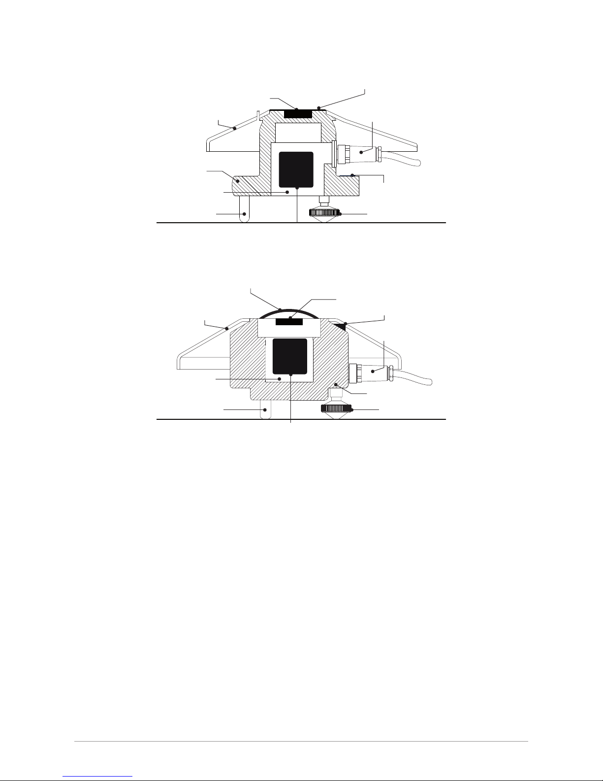
1.2 Key parts of the SGR3
1.3 Key parts of the SGR4
10
silicon window
housing
detector
sun shield
bubble level
connector
fixed foot adjustable feet
desiccant
desiccant
glass window
housing
detector
sun shield
bubble level
connector
fixed foot adjustable feet
smart interface
smart interface
Page 11

Please follow the instructions in this section carefully for the mechanical and electrical installation of the SGR series pyrgeometers.
Do not turn on power to the instrument until instructed to do so.
Note Do not connect the instrument to a computer until instructed to do so.
Note Do not turn on power to the operating computer until instructed to do so.
2.1 Included with the product
Check the contents of the shipment for completeness (see below) and note whether any damage has occurred during transport.
If there is damage, a claim should be filed with the carrier immediately. In the case of damage and/or the contents are incom-
plete, contact your local Kipp & Zonen representative or e-mail the Kipp & Zonen customer and product support department at:
support@kippzonen.com
Although all SGR radiometers are weatherproof and suitable for harsh environmental conditions, they have some delicate
mechanical parts. Please keep the original packaging for safe transport of the radiometer to the measurement site or for use
when returning the radiometer for calibration.
The following items are included with SGR series pyrgeometers:
1. Radiometer
2. Sun shield
3. Optional cable, pre-wired with 8-pins connector or connector only for customer cable
4. Test reports
5. Instruction sheet
6. Radiometer fixing kit
The calibration certificate supplied with the instrument is valid for 1 year from the date of first use by the customer, subject to the
variations in performance due to specific operating conditions that are given in the instrument specifications. The calibration
certificate is dated relative to the time of manufacture, or recalibration, but the instrument does not undergo any sensitivity
changes when kept in the original packing and not exposed to light. From the moment the instrument is taken from its packaging
and exposed to irradiance the sensitivity will deviate slightly with time. See the 'non-stability' performance (maximum sensitivity
change per year) given in the radiometer specification list.
2.2 Mechanical installation
The mechanical installation of the radiometer depends upon the measuring purpose. Different measuring methods will be
explained in the next paragraphs.
2.2.1 Installation for measurement of long-wave downward radiation
The following steps must be carefully taken for optimal performance of the instrument. The tools required to fit an SGR series
pyrgeometer to a support are a 4 mm (M5 socket head screw) Allen key and a 8 mm (M5 nut) wrench / spanner.
2. Installation and operation
11
Page 12
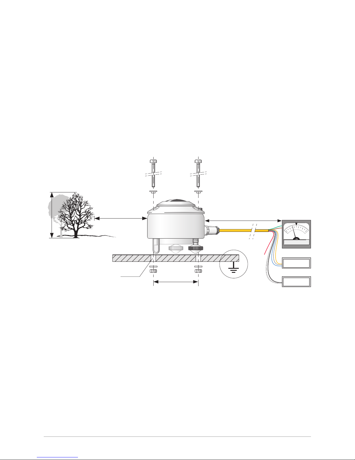
SGR-V or SGR-A
h
>10 x h
Ø5.2 mm (2x)
65 mm
max. 100 m
5 to 30 VDC
power supply
Modbus® RS-485
V / mA
0.0
0.2
0.4
0.6
0.8
1.0
Pyrgeometer installation
Step 1. Location
Ideally the site for the pyrgeometer should be free from any obstructions to the horizon above the plane of the sensing element. If
this is not possible, the site should be chosen in such a way that any obstruction over the azimuth range should have an elevation
not exceeding 10°. In particular, no sources of heat (such as ventilation / heating outlets) should be within the field of view.
Step 2. Mounting
The SGR pyrgeometer is provided with two holes for 5 mm bolts. Two each of stainless steel bolts, washers, nuts and nylon insulation
rings are provided in the fixing kit. The pyrgeometer should first be secured lightly with the bolts to a solid and stable mounting stand
or platform. After in recalibration the nylon insulators must be replaced with new ones to prevent corrosion.
The mounting stand temperature can vary over a wider range than the air temperature. Temperature fluctuations of the pyrgeometer
body can produce offset signals, therefore it is recommended to isolate the pyrgeometer thermally from the mounting stand by
placing it on its levelling screws. Ensure that there is a good electrical contact with earth to conduct away currents in the cable
shield induced by lightning.
Note After recalibration and/or reinstallation the nylon insulators must be replaced with new ones to maintain durability.
Step 3. Orientation
In principle no special orientation of the instrument is required, although the World Meteorological Organisation (WMO)
recommends that the signal lead is pointed towards the nearest pole, to minimise heating of the electrical connections.
Step 4. Level pyrgeometer
Accurate measurement of the global radiation requires proper levelling of the thermopile surface. Level the instrument by turning
the two levelling screws to bring the bubble of the spirit level centrally within the marked ring. For easy levelling, first use the
screw nearest to the spirit level. When the SGR4 pyrgeometer is placed horizontally using the bubble level, or when it is mounted
with its base directly on a horizontal plane, the thermopile is horizontal within 0.1°. For the SGR3 this is 0.2°.
12
Page 13
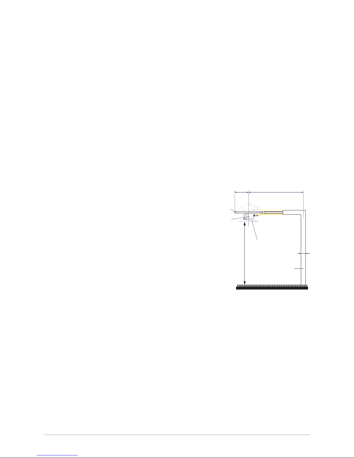
Upward long-wave radiation
Mounting plate
R S
h d
lower screen
always point the cables
to the nearest pole
pyrgeometer
Mast
The mounting device should not interfere significantly with the field
of view of the instrument. The upper plate prevents excessive heating
of the pyrgeometer body by solar radiation and, if large enough, it
keeps the lower screen free of precipitation. The lower glare screen
prevents direct illumination of the window by the sun at sunrise and
sunset and is available as an accessory kit for the SGR series.
The mast shown intercepts a fraction D/2πS of the radiation coming
from the ground. In the most unfavourable situation (sun at zenith)
the pyrgeometer shadow decreases the signal by a factor R²/H².
A rule of thumb is:A black shadow with radius = 0.1 H on the field
below decreases the signal by 1% and 99% of the signal will
originate from an area with radius 10 H.
Step 5. Secure pyrgeometer
Secure the pyrgeometer tightly with the two stainless steel bolts. The two nylon washers prevent contact corrosion. Ensure that
the pyrgeometer maintains the correct levelled position!
Step 6. Fit cable and sun shield
Locate the cable plug correctly in the radiometer socket (it only fits one way) and screw the plug locking ring hand-tight. Finally,
clip on the sun shield to prevent excessive heating of the radiometer body. The bubble level is visible through the top of the
pyrgeometer sun shield for routine checks.
2.2.2 Installation for measurement of radiation on inclined surfaces
It is advised to pre-adjust the levelling screws on a horizontal surface for easy orientation of the instrument parallel to the inclined
surface. Because the temperature of the mounting stand is expected to rise considerably (more than 10 °C above air temperature),
the housing must be thermally isolated by the levelling screws from the stand. This will promote a thermal equilibrium between
the window and the housing and decrease zero offset signals.
2.2.3 Installation for measurement of upward long-wave radiation
In the inverted position the pyrgeometer measures radiation from the ground. According to the WMO the height should be 1 to 2 m
above a uniform surface covered by short grass.
2.2.4 Installation for shaded measurement of downward long-wave radiation
For measuring atmospheric radiation with SGR pyrgeometers it is desirable to shield the instrument from the direct short-wave
solar radiation which may heat up the pyrgeometer window and cause significant thermal offsets. The direct solar radiation is
intercepted by a small disk or sphere. The shadow of the disk must cover the pyrgeometer window completely. However, to follow
the sun's apparent motion, a power-driven tracking device is necessary.
This can be done using a Kipp & Zonen sun tracker, such as the model SOLYS2, designed to track the sun accurately under all
weather conditions. More information about the combination of pyrgeometer and tracker is given in the sun tracker manual.
Alternatively, a static shadow ring can be used to intercept the direct solar radiation; but it is less accurate and may require periodic
manual adjustment. At times the shadow ring also intercepts a proportion of the diffuse sky radiation. Therefore, corrections for this
to the recorded data are necessary.
13
Page 14
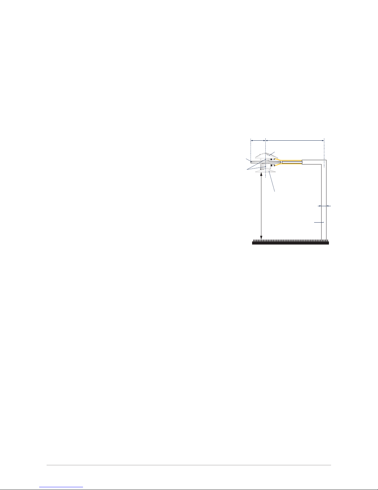
Net radiation configuration
Mounting plate
Upper screen
R S
h d
lower screen
always point the cables
to the nearest pole
pyrgeometer
Mast
The requirements for installation of the upper and lower pyrgeometers
are the same as in paragraphs for downward and upward long-wave
radiation. According to the WMO the pyrgeometer configuration
should be 1 to 2 meter above an uniform surface covered by short
grass.
The mast shown intercepts a fraction D/2πS of the radiation that is
coming from the ground. In the most unfavourable situation (sun at
zenith) the pyrgeometer shadow decreases the signal by a factor R²/H².
When determining the net long-wave radiation, it is not strictly necessary
to record the pyrgeometer housing temperatures. Assuming that the
temperatures of the upper and lower housings are equal, it can be
cancelled from the equation for net-radiation.
Kipp & Zonen produces a universal shadow ring, model CM121, which is suitable for use at all latitudes. In the CM121 manual,
installation instructions and correction factors are given.
In practice the SGR4 does not require shading from direct short-wave solar radiation because the window-heating effect, when
suitably ventilated, is negligible due to the unique construction of the pyrgeometer.
2.2.5 Installation for measurement of net long-wave radiation
A net pyrgeometer measures both the downward atmospheric long-wave radiation and the upward long-wave radiation from the
surface below. It can be configured from two SGR-series pyrgeometers and a suitable mounting plate. In the case of the SGR3, two
instruments can be simply mounted back-to-back and an optional mounting rod fitted.
However, if the upward and downward radiation components are to be measured separately it is necessary to record the individual
housing temperatures to calculate the radiation values.
Using the combination of a net pyrgeometer (two SGR3 or SGR4 instruments) and an albedometer (two SMP6 or SMP11) the net
total radiation (energy balance) can be calculated with high accuracy from the four component values. Problems with dew
deposition, frost, etc, can be minimised by using the Kipp & Zonen CVF4 ventilation unit with optional heating.
This has many advantages over conventional net total radiation sensors with plastic (polyethylene) windows. These cannot
provide individual short and long-wave radiation values and cannot separate upward and downward contributions. The soft
plastic windows do not fully protect the sensor from the thermal effects of wind and rain, are easily soiled, are difficult to clean
and require regular replacement.
14
Page 15
2.3 Electrical connections
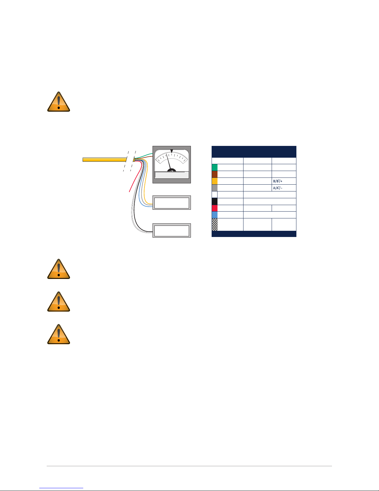
The SGR pyrgeometers can be supplied with a waterproof connector pre-wired to 10 m of high quality yellow cable with 8 wires
and a shield covered with a black sleeve. Longer cables are available as options. The colour code of the wires and the connector
pin numbers are shown below and on the instruction sheet.
Special attention is needed to prevent power or ground loops when connecting the SGR to multiple readout devices.
Connecting the RS-485 to a grounded circuit and the analogue output to a floating circuit can cause unacceptable
ground loops. This may cause differential voltages outside the SGR specifications and will damage the unit. We
recommend using either the analogue or the digital output but not both. The maximum differential between either
of the Modbus® RS-485 lines (yellow and grey) and the power ground / RS-485 common line (black) is 70 VDC.
First connect all wires before plugging into the radiometer
The shield of the cable is connected to the aluminium radiometer housing through the connector body. Preferably,
secure the radiometer with its levelling screws on a metal support with a good connection to ground (e.g. by using
a lightning conductor) and do not connect the cable shield at the readout end.
If there is no good ground connection at the pyrgeometer, the shield at the cable end should be connected to ground
at the readout equipment. Lightning can induce high voltages in the shield but these will be led off at the pyrgeometer
or readout equipment.
Note Long cables may be used, but the cable resistance must be smaller than 0.1% of the impedance of the readout
equipment for the analogue outputs and may affect the baud rate of the RS-485 digital connection.
2.3.1 Power connection
The minimum power supply voltage for SGR pyrgeometers is 5 VDC. However, for optimal performance it is advised to use
12 VDC, especially when long cables are used. 5-volt power can only be used in combination with a short cable, maximum 10 m.
It is advised to protect the output of the power supply with a fast blowing fuse of maximum 250 mA rating.
Radiometer Connection
Wire Function Connect with
Red
Blue
HousingShield
Not connectedNone
Modbus® common / Ground
Analogue out V+/4-20 mA(+)
Analogue ground V
-
/4-20 mA(-)
Modbus® RS-485
Modbus® RS-485
Power 5 to 30 VDC
(12 V recommended)
Power ground / RS-485 Common
Ground *
White
Black
Yellow
Brown
Green
Grey
5
1
2
8
7
* Connect to ground if radiometer not grounded
4
6
3
SGR-V or SGR-A
5 to 30 VDC
power supply
Modbus® RS-485
V / mA
0.0
0.2
0.4
0.6
0.8
1.0
15
Page 16
Typical power consumption SGR-V for maximum output (1 V)
5 VDC 50 mW (approx. 10.0 mA)
12 VDC 55 mW (approx. 4.5 mA)
24 VDC 60 mW (approx. 2.5 mA)
.
Maximum power consumption 65 mW at the highest input voltage.
Maximum input current 12.5 mA at the lowest input voltage.
Maximum inrush current 200 mA.
Typical power consumption SGR-A for max output (20 mA)
5 VDC 77 mW (approx. 28 mA with 100 Ω load resistor)
12 VDC 83 mW (approx. 24 mA with 100 Ω load resistor)
24 VDC 100 mW (approx. 6 mA with 100 Ω load resistor)
The above mW values represent the dissipation within the SGR-A. For the total power the energy in the load resistor has to
be added.
For supply voltages below 12 Volts or above 20 Volts it is advised to use a load resistor of less than 500 Ω to keep the power
consumption as low as possible.
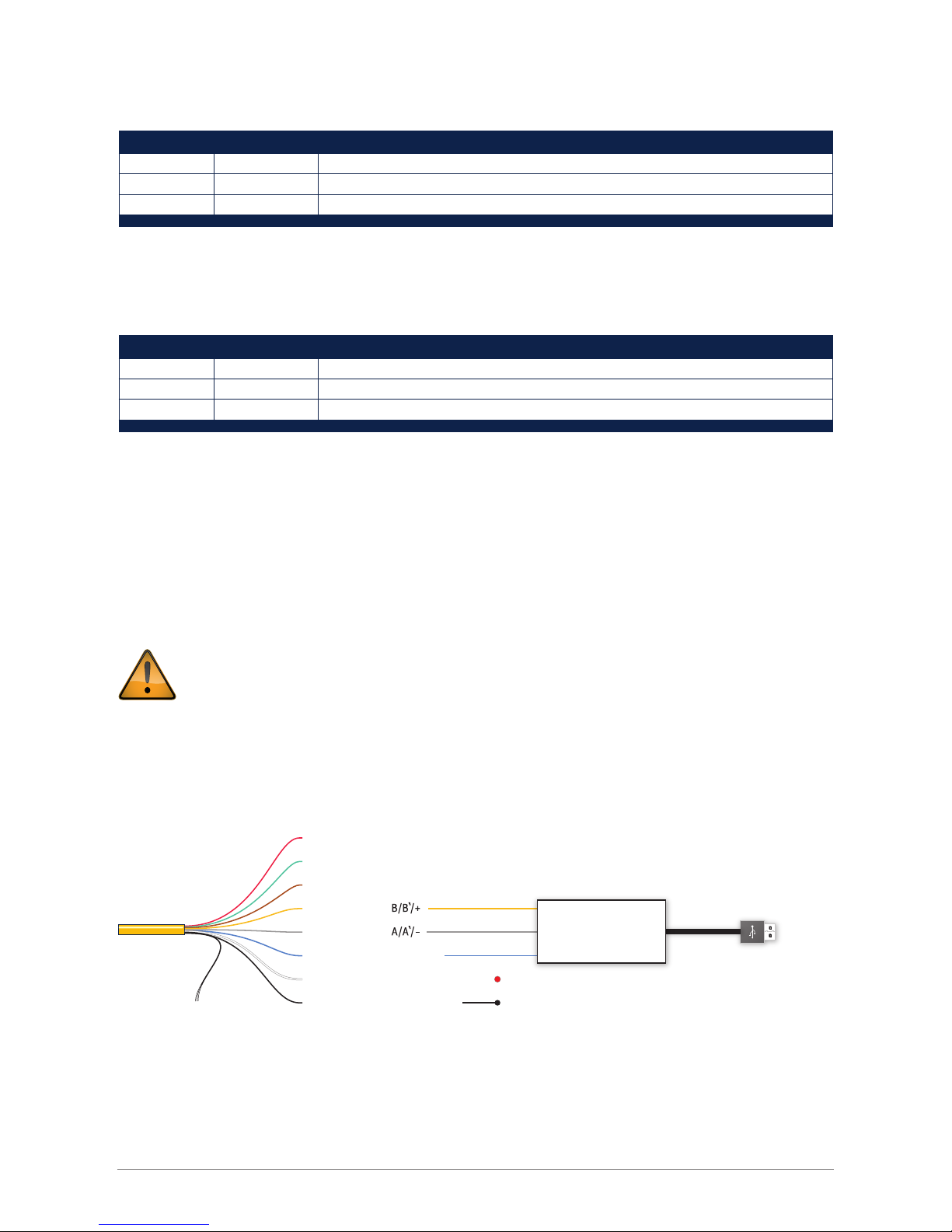
2.3.2 Data connection
Connection to a Personal Computer by Universal Serial Bus (USB)
The connection depends on the use of a RS-485 to USB converter.
The converter must have galvanic isolation between the inputs and outputs to prevent possible damage to the SGR
digital interface. This is particularly an issue with portable computers (laptops, etc.) in which the power supplies
can generate large voltage spikes.
A suitable converter is the model USOPTL4 from B & B Electronics. One end has the USB connector to the PC the other end has
a connector with screw terminals for the instrument wires. This RS-485 converter is powered from the USB interface, so no
additional power adaptor is necessary.
*Note Switches on the converter should be set for RS-485, 2-wire operation and Echo off.
Shield - ground connection
SGR connections to USB
USB to PC
Not connected
Analogue out +
Analogue out
-
Modbus® RS-485
Modbus® RS-485
Modbus® common / Ground
Power 5 to 30 VDC
Power ground / RS-485 common
+ V
-
V
RS-485 / USB converter
Common
*
16
Page 17
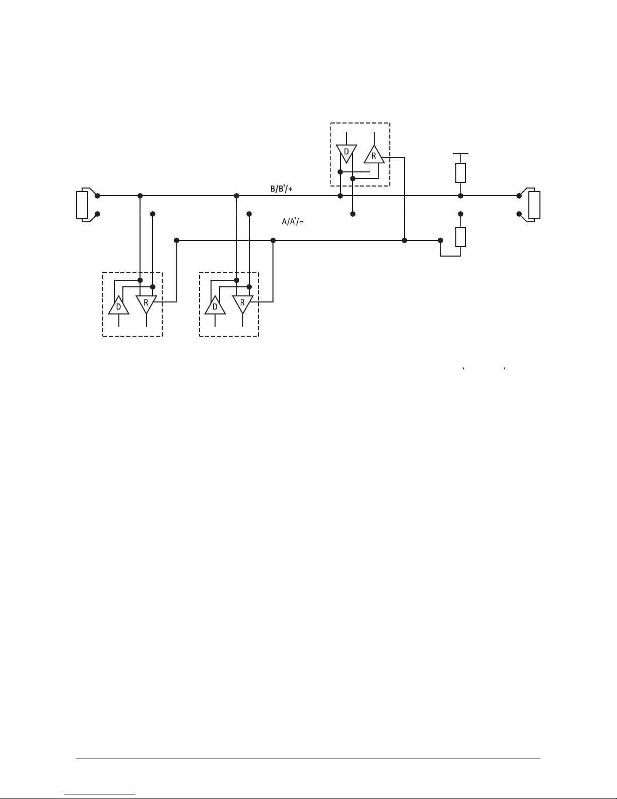
Connection to a RS-485 Network
The digital interface can be connected to a 2-wire RS-485 network as shown below.
The slaves and master may be a SGR pyrgeometer or other devices. If a SGR pyrgeometer is the last device on the network a
line terminator (LT), consisting of a 120 Ω or 150 Ω resistor, must be connected between terminals A/A'/- and B/B'/+. Never
place this line termination on the derivation cable. It is also required to install the pull up and pull down resistors as shown.
The value of these resistors must be between 650 Ω and 850 Ω.
2.3.3 Analogue voltage output
The SGR-V (voltage output versions) have been factory set such that an output of 0 Volts represents 0 W/m² (this will never be
reached in practice), and the full-scale output of 1 Volt represents 1000 W/m².
The voltage output range in W/m² can be changed by the user with the supplied PC software. The maximum recommended
irradiance for all SGR pyrgeometers is 1000 W/m².
The default setting 0 to 1 Volt represents 0 to 1000 W/m².
The downward atmospheric long-wave radiation (
L
d↓
) for the default setting can be simply calculated as shown below.
L
d↓
= Downward atmospheric long-wave radiation [W/m²]
V = Output of radiometer [Volt]
If the pyrgeometer is used in atmospheric conditions it is advised to keep the range as factory default.
Slave 1 Slave n
Master
Common
Balanced pair
LT LT
Pull down
Pull up
5 V
L
d↓
= (V x 1000)
17
Page 18
2.3.4 Analogue current output
The SGR-A (current output versions) have been factory set such that an output of 4 mA represents 0 W/m² and the full-scale
output of 20 mA represents 1000 W/m².
The current output range in W/m² can be changed by the user with the supplied PC software. The maximum recommended
irradiance for the SGR pyrgeometers is 1000 W/m².
Negative inputs will make the output go below 4 mA and no zero offset is needed. For the default setting of 4 to 20 mA representing
0 to 1000 W/m². The irradiance value (
L
d↓
) for the default setting can be simply calculated as shown below.
L
d↓
= Downward atmospheric long-wave radiation [W/m²]
mA = Output of radiometer [mA]
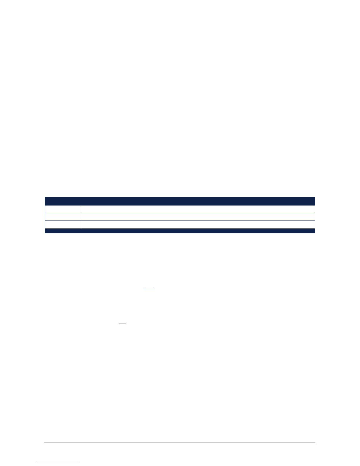
2.3.5 Recommended cable types
Where cables need to be extended, or the customer prefers to provide their own cables, they should be suitable for outdoor used
and UV resistant.
Recommended types
RS-485 Ethernet CAT 5 shielded twisted pair (STP)
0 to 1 V Shielded 2-core signal cable
4 to 20 mA Shielded twisted pair control cable
2.4 Operation
After completing the installation the pyrgeometer will be ready for operation. The downward atmospheric long-wave radiation
is calculated automatically inside the pyrgeometers with formula L
d
by measuring the detector output voltage U
emf
[µV], the
housing temperature T
b
[K], and taking the sensitivity calibration factor S [µV/W/m²] into account.
Note The net radiation term (U
emf
/S) is mostly negative, so the calculated downward atmospheric long-wave radiation
is smaller than the detector’s upward irradiance (5.67 • 10
-8
• T4).
In the Baseline Surface Radiation Network (BSRN) manual (WMO/TD-No.897) an extended formula is described. This formula
corrects for window heating and so called ‘solar radiation leakage’. Due to the very low window heating offset and optimal
spectral cut-on wavelength, these corrections are not necessary for the pyrgeometer.
Ld↓ = (mA-4) x (1000/16)
18
formula L
d
= Downward atmospheric long-wave radiation [W/m²]
Net radiation (difference between the downward [W/m²]
= longwave radiation emitted from the atmosphere
and the upward irradiance of the SGR detector)
= Upward irradiance of the SGR detector [W/m²]
Ld= + 5.67 • 10
-8
• T
4
U
emf
S
b
L
d
5.67 • 10
-8
• T
4
b
U
emf
S
b
Page 19

To be certain that the quality of the data is of a high standard, care must be taken with daily maintenance of the pyrgeometer.
Once a voltage measurement is taken, nothing can be done to retrospectively improve the quality of that measurement.
During field measurements the pyrgeometer is exposed to varying atmospheric conditions with typical radiating properties.
Therefore we define the two most common conditions as ‘overcast sky’ and ‘clear sky’.
2.4.1 Overcast sky
Typical for a cloudy overcast sky is that radiation emitted by the earth is absorbed 100% by the clouds. Therefore, the overcast
sky will re-emit the radiation (
L
d↓
) 100%.
In theory, the net radiation (U
emf
/S) will be zero, so the pyrgeometer detector output voltage (U
emf
) will be zero. In practice,
the detector output shows a small negative voltage (a few W/m²), due to a small heat exchange between the relatively warm
pyrgeometer and the colder sky.
In this case the calculated atmospheric long-wave radiation (
L
d↓
) shows a relatively large positive value. In the case of rain, the
detector output will read zero, because water deposited on the pyrgeometer window is a perfect infrared absorber.
Cloudy overcast sky condition
2.4.2 Clear sky
Clear sky conditions differ in that there is a relatively large heat loss caused by the atmospheric window. The amount of
re-emitted radiation by a clear sky is smaller compared to the overcast sky condition. Because of the heat loss in the upward
direction, the thermopile hot junctions will cool down and show a relatively large negative net radiation value (from -90 to
-130 W/m²). Therefore, the calculated atmospheric long-wave radiation (
L
d↓
) shows a relative small positive value.
Clear sky condition
Atmosphere T
atm
Earth’s surface T
earth
>T
atm
Net radiation (-90 to -130 W/m
2
)
Downward radiation
(Relatively small value)
Upward radiation
Atmosphere T
atm
Earth’s surface T
earth
>T
atm
Net radiation (0 to -5 W/m
2
)
Downward radiation
(Relatively large value)
Upward radiation
19
Page 20

2.4.3 Measurements during a sunny day
The SGR4 differs from all other pyrgeometers in that it allows accurate daytime measurements on sunny days without the need
for a shading device. Due to the unique construction of the SGR4, solar radiation of up to 1000 W/m² induces window heating
of less than 4 W/m² in the overall calculated downward radiation.
Formula 1 can be applied without any problems with the following exception; one must take note of the amount of infrared
radiation in the solar spectrum. The amount of solar infrared radiation depends on many parameters; for example the water vapour
content in the atmosphere (humidity), location of the SGR4 at a certain altitude and the sun’s declination angle. The next graph
indicates the possible infrared radiation in the solar spectrum in the case of low water content in the atmosphere. The amount of
solar infrared detected at the SGR4 (and the SGR3) is expected to be very low (0 to 3 W/m²) because of the filter cut-on at 4.5 µm.
Other types of pyrgeometers can exhibit 0 to 10 W/m².
Direct solar irradiance in Davos, Switzerland at solar noon in mid-September
2.5 Measurement uncertainty
When a pyrgeometer is in operation, the performance of it is correlated to a number of parameters, such as temperature, level of
irradiance, angle of incidence, etc. Normally, the supplied sensitivity figure is used to calculate the irradiances. If the conditions
differ significantly from calibration conditions, uncertainty in the calculated irradiances must be expected.
Kipp & Zonen expects maximum uncertainty below 3% for daily totals for the SGR4 pyrgeometer. This remaining uncertainty can
be reduced further if the sensitivity of the pyrgeometer under the prevailing conditions is used, with corrections calculated
from the effects of parameters such as temperature and non-linearity. This is especially convenient with a programmable data
acquisition system.
Amount of Longwave Radiation in the Solar Spectrum
Wavelenght [µm]
Power [W cm
-2
µm]
(Davos at solar noon, mid of September)
0.00125
0.001
0.00075
0
2.5 5 7.5 10 12.5 15
0.000250.00025
Filter cut-on
20
Page 21
For the SGR4 the effect of each parameter on the sensitivity can be shown separately. The non-linearity error, the sensitivity
variation with irradiance, is the same for any SGR4.
Non-linear sensitivity variation with irradiance of a SGR4 pyrgeometer
2.6 Maintenance
Once installed the pyrgeometer needs little maintenance. The window must be cleaned and inspected regularly, ideally every
morning. On clear windless nights the window temperature of horizontally placed pyrgeometers will decrease, even to the dew point
temperature of the air, due to infrared radiation exchange with the cold sky. (The effective sky temperature can be 30°C lower than
the ground temperature). In this case dew, glazed frost or hoar frost can be precipitated on the top of the window and can stay there
for several hours in the morning. An ice cap on the window is a strong diffuser and increases the pyrgeometer signal drastically, up
to 100% in the first hours after sunrise. Hoar frost disappears due to solar radiation during the morning, but should be wiped of as
soon as possible manually.
The window of the pyrgeometer can be ventilated continuously by a heated blower to keep the window above the dew point
temperature. The need for heating strongly depends upon local climatological circumstances. Generally, heating is advised during
cold seasons when frost and dew can be expected. The Kipp & Zonen CVF4 ventilation unit is specially designed for unattended
operation under most weather conditions and has a choice of heating levels.
Note The SGR3 pyrgeometer can be used with the CVF4 ventilation unit but is less effective.
A periodic check is to ensure that the pyrgeometer is level. The pyrgeometer sensitivity changes with time and with exposure to
radiation. Calibration every two years is advised.
To keep the detector and electronics dry and to prevent condensation forming inside the windows with temperature changes an
internal desiccant is used to absorb humidity within the pyrgeometer and lasts for 10 year. The desiccant will be exchanged when
these instruments comes back to a Kipp & Zonen service location for recalibration.
Horizontal
90 degrees tilt
-250
-1
-0.5
0
0.5
1
0
Irradiance [W/m2]
Non-linearity
Sensitivity variation
[%]
250
21
Page 22

22
Page 23

.
Below is a brief description of the accessories available for SGR series pyrgeometers. Detailed information can be found on our
website, where the brochures and manuals for these accessories can be viewed and downloaded.
3.1 Diffuse radiation measurement
For measuring diffuse radiation a shading device is required. Kipp & Zonen can offer several options for SGR pyrgeometers:
Shadow ring CM121B for a SGR3 or an unventilated SGR4
Shadow ring CM121C for a ventilated SGR4
This shadow ring needs to be adjusted manually every 3-5 days and corrections made for the sky obscuration by the ring.
An automated and more accurate way to measure diffuse radiation is to use an automatic sun tracker fitted with a shading
mechanism:
SOLYS2 sun tracker + shading ball assembly
SOLYS Gear Drive sun tracker + shading ball assembly
3.2 Ventilation
To further improve measurement accuracy of the SGR4 pyrgeometers the CVF4 ventilation unit can be used. CVF4 has a tacho
output to monitor the fan speed and 5 or 10 Watt heater. The advantages of a CVF4 are:
Lower thermal offsets
No precipitation or condensation on the window
Less dirt on the window
Frost, snow or ice can be melted
Less frequent cleaning required
3.3 Mountings
For mounting pyrgeometers the following plates and brackets are available:
Mounting rod for SGR3
CMF1 mounting fixture with rod for mounting one or two unventilated SGR4’s
CMF4 mounting plate with rod for mounting one or two ventilated SGR4’s
CMB1 mounting bracket to fix and adjust a mounting rod to a mast, pole or wall
Adjustable tilt mounting kit allows tilting of a SGR pyrgeometer, It has a clear scale for setting the desired angle.
3.4 Cables
Different cable lenghts with pre-wired waterproof connector plug, or a connector only can be supplied.
10 m cable with connector
25 m cable with connector
50 m cable with connector
Connector only, no cable
3. Accessories
23
Page 24

24
Page 25

25
.
The SmartExplorer software allows you to configure a smart sensor and to collect real-time data. SmartExplorer runs on a PC
with Windows Vista, 7 or 8 and when installing downloads the .NET 4.5 frame work from the Microsoft Server. When using the
software on site, make sure the software is already installed on your laptop.
To connect a smart radiometer to a PC, a RS-485 to USB converter is required. Recommended is using an isolated version like
the ‘USOPTL4’ from B&B for safety and protection of the PC.
• Configuration makes it possible to configure a smart sensor ‘out of the box’ and test the smart sensor before the sensor is used
in an operational network.
• The SmartExplorer software can use a RS-485 to USB or Ethernet interface to connect to a PC
• Collecting data makes it possible to store data from the smart sensor in a comma separated file. The comma separated file is
created at the beginning of every new day or at the beginning of the first day of the week.
• The SmartExplorer software can also be used to monitor and/or log up to 10 instruments simultaneously and works with all
smart radiometers (SMP, SHP, SGR, SUV)
Please check the separate SmartExplorer manual for detailed information about the set-up, monitoring and data logging of the
smart sensors. The latest version of the manual can be downloaded the from the relevant product page under the tab ‘Download’
from our website.
The factory default communication parameters for all Smarts are:
• The factory default Baud rate of a smart sensor is ‘19200 baud’
• The factory default Size and Parity is ‘8 bits - even - 1 stopbit’
• The factory default Modbus® address is 1
4. SmartExplorer software and Modbus® communication
Page 26

26
Page 27

The detector of the Kipp & Zonen SGR series pyrgeometer is based on a passive thermal sensing element called a thermopile.
Although the detector construction differs from model to model, the fundamental working principle is applicable to all SGR series
radiometers.
The thermopile responds to the total power absorbed by the black surface coating, which is a nonspectrally selective paint, and warm
up. The heat generated flows through a thermal resistance to the heat-sink (the pyrgeometer body). The temperature difference
across the thermal resistance of the detector is converted into a voltage as a linear function of the absorbed long-wave irradiance.
The rise of temperature is easily affected by wind, rain and thermal radiation losses to the environment ('cold' sky). Therefore the
detector is shielded by a silicon meniscus window (the entry-level SGR3 has a flat silicon window). To keep the detector and
electronics dry and to prevent condensation forming inside the windows with temperature changes an internal desiccant is used
to absorb humidity within the pyrgeometer.
5.1 Window
The inner surface of the silicon window has an interference filter deposited on it for transmitting the long-wave radiation and
blocking the short-wave solar radiation from reaching the detector. The silicon window material and the deposited ‘solar blind’
filter defines the spectral measurement range of the pyrgeometer.
The silicon window allows transmittance of the atmospheric long-wave radiation up to approximately 42 µm and about 50 to
60% of the radiation spectrum will be transmitted through to the detector. The outer surface of the window has a hard-carbon,
diamond-like layer, deposited as additional protection against environmental influences in harsh environments and to smooth
out the window transmission beyond 30 µm.
The solar blind filter is opaque to radiation below 4.5 µm, known as the cut-on wavelength. Currently most pyrgeometers have
their cut-on at a lower wavelength. Problems may occur in the case of clear sunny days with low humidity. In the solar spectrum
between 2.5 and 4.5 µm there can still be an amount of infrared solar radiation up to 10 W/m², which should not be included in
the measurement. This unwanted fraction is blocked in the SGR4 by the filter coating.
SGR4 uses a specially designed pure silicon window. Although the window is not hemispherical, SGR4 has a 180° field of view
with good cosine response. A big advantage of the meniscus shaped window over the typical hemispherical window is the
ability to deposit more uniform coatings on the window surface. Deposition of a uniform filter coating on a strongly curved
surface is very difficult and unpredictable process. To avoid these problems Kipp & Zonen developed a window with excellent
optical quality due to the optimised shape and coating uniformity.
The solar radiation absorbed by the window is conducted away very effectively by a unique construction in the SGR4. Even in
full sunlight the window heating effect is very low compared to that of other pyrgeometers on the market. This allows accurate
daytime measurements without the need for a shading disk. It also eliminates the need for window heating compensation by
using the correction formula and window temperature sensors.
5.2 Detector
The thermopile sensing element is made up of a large number of thermocouple junction pairs connected electrically in series. The
absorption of thermal radiation by one of the thermocouple junctions, called the active (or ‘hot’) junction, increases its temperature.
The differential temperature between the active junction and a reference (‘cold’) junction kept at a fixed temperature produces an
electromotive force directly proportional to the differential temperature created. This is a thermoelectric effect. The sensitivity of a
pyrgeometer depends on the individual physical properties of the thermopile and construction. The sensitivity of each thermopile
is unique and therefore each radiometer has unique calibration factor, even with the same radiometer model.
5. Principle components of pyrgeometers
27
Page 28

On the top surface of the sensor a black paint is deposited which has a very rough structure containing many micro-cavities that
effectively ‘trap’ more than 95% of the incident radiation in a broad spectral range. Furthermore, the spectral selectivity is less
than 3%. This means that within the spectral range of the pyrgeometer, the absorption for each wavelength is equal to within
3%. The black painted sensing element forms the detector. Considering the long-term stability of the instrument, the black paint
is one of the most crucial and delicate parts of the pyrgeometer. Kipp & Zonen black paint gives the best possible stability over
a long period of time under all meteorological circumstances.
5.3 Temperature sensor
The housing temperature sensor is a crucial part of a pyrgeometer and is needed to calculate the downward long-wave radiation
component. The body temperature sensor represents the ‘absolute’ temperature of the detector surface and therefore it is
mounted close to the cold junctions of the detector. A housing temperature sensor is fitted as standard to the SGR pyrgeometers.
5.4 Housing
The radiometer housing accommodates all fundamental pygeometer parts. The anodized Aluminium parts are light weight and
give a high mechanical and thermal stability to the instrument. Due to its fine mechanical construction all pyrgeometers are
virtually sealed and comply to the international standard IP 67. Each pyrgeometer model can be leveled by using the bubble
level and two leveling feet. For ease of maintenance the bubble level is situated next to the window of the instrument and due
to the special shape of the sun shield it is visible from above. The sun shield acts to protects all the external parts from radiation
and to reduce solar heating of the housing.
5.5 Cable and connector
For ease of installation and replacement during recalibration of the radiometer, the SGR series are provided with a weather
proof signal cable connector.
Kipp & Zonen radiometers use a custom-made cable that is selected with a high UV resistance and low electrical resistance.
The shield of the cable is connected to the metal body of the connector and preferably should be connected to ground at the
readout equipment. Cables come pre-wired to the connector plug in a range of lengths.
28
Page 29

6.1 Spectral range
The spectral properties of the pyrgeometer are mainly determined by the filter characteristics of the silicon window and the
coatings. The application is primarily to measure long-wave downward atmospheric radiation. The spectral range is from 4.5 to
42 µm, where most of this radiation is present.
Pyrgeometer spectral window properties
The atmosphere is transparent to long-wave radiation emitted by the Earth’s surface in certain wavelength intervals, particularly
within a spectral range of approximately 8 to 14 µm. This is called the ‘atmospheric window’. Within this spectral range the Earth
is able to maintain an equilibrium temperature by losing a certain quantity of heat gained each day from the sun.
The sun radiates approximately as a blackbody at an equivalent temperature of 5770K. Almost 99% of its emitted energy is
contained in wavelengths less than 4µm, called short-wave radiation. The equivalent radiant temperature of the Earth’s surface
is about 275K. More than 99% of this energy is emitted at wavelengths greater than 3 µm and is called long-wave, thermal, or
infrared radiation.
Downward long-wave radiation is a result of atmospheric re-emission. Re-emission is the reversible effect of absorption of
long-wave radiation emitted by the Earth and by chemical elements such as water (H₂O), Oxygen (O₂), Ozone (O₃), Carbon
dioxide (CO₂), etc. These elements are the main emitters of long-wave radiation in the atmosphere. The remaining unabsorbed
portion of the Earth’s radiation escapes into outer space. Under clear skies an object can be cooled below ambient air tempera-
ture by radiative heat loss to the sky.
Observing the earth from outer space, a blackbody is seen in a range of 8 to 14 µm with a temperature of 14 °C and outside this
wavelength range a blackbody of -60°C. Under clear sky conditions in a reverse direction, outer space can be observed in the
same spectral range.
Atmospheric radiation
6.2 Sensitivity
The radiometer thermopile sensitivity is mainly determined by the physical properties of the detector itself. The thermoelectric
power, thermal conductivity of the junctions and the overall dimensions of the sensing element are related to its sensitivity.
6. Pyrgeometer physical properties
Wavelenght [µm]
Transmittance [%]
100
50
0
1 10 100
SGR4 window transmittance
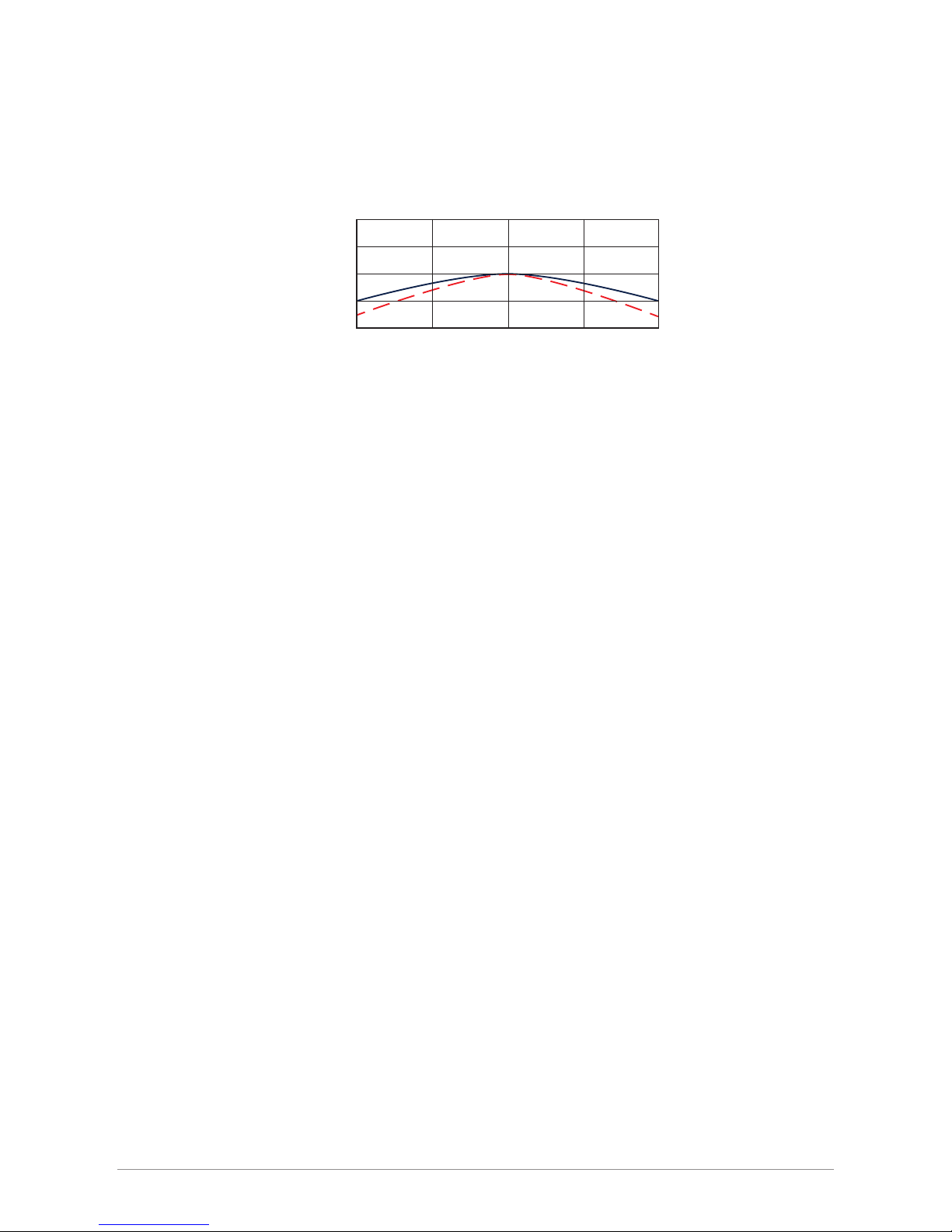
Amplitude
Wavelength [µm]
5
75°
60°
0°
90°
0
5 10 15 20 25
29
Page 30

6.3 Response time
Any measuring device requires a certain time to react to a change in the parameter being measured. The radiometer requires
time to respond to change in the incident radiation. The response time is normally quoted as the time for the output to reach
95% (sometimes 63%) of the final value following a step-change in irradiance. It is determined by the physical properties of the
thermopile and the radiometer construction. SGR series pyrgeometers have a fast response, which makes them suitable for
measuring far infrared radiation (FIR) under variable weather conditions.
6.4 Non-linearity
The non-linearity of a pyrgeometer is the percentage deviation in the sensitivity over a net irradiance range from -250 to +250 W/m²
compared to the sensitivity calibration irradiance of -100 W/m². The non-linearity effect is due to convective and radiative heat
losses at the black absorber surface which make the conditional thermal equilibrium of the radiometer non-linear.
6.5 Temperature dependence
The sensitivity change of the pyrgeometer with ambient temperature is related to the thermodynamics of the radiometer
construction. For the SGR3 this dependency is measured for a large series of instruments and the average dependency is corrected
by the Smart Interface. This gives the SGR3 a better temperature performance than the CGR3.
For every SGR4 the temperature dependency is individually measured and corrected. This correction is over a range of -40 to +70°C.
The corrected value is available via the analogue and digital outputs.
6.6 Tilt error
This is the deviation from the sensitivity at 0° tilt (exactly horizontal) over the range from 0° to 90° tilt. The tilt response is
proportional to the incident radiation. The error could be corrected for, in applications where it is necessary to install the
pyrgeometer on an inclined surface, but is usually insignificant.
6.7 Window heating oset
Currently the major source of error concerning common pyrgeometer measurements is caused by the so-called ‘window heating
offset’. When a pyrgeometer is exposed to the sun, heating of the silicon window occurs due to absorption of solar radiation by the
material. As a consequence the window of most types of pyrgeometer will heat up proportionally to the solar irradiance.
The resulting temperature difference between window and thermopile will cause heat transfer by radiation and convection to the
sensor. This affects the net thermal radiation as measured by the thermopile and is commonly referred to as the ‘window heating
offset’. The result is measurement of a too high value for downward long-wave radiation.
This offset is not easily reduced by ventilation, which only cools off 50 W/m²/°C at maximum while solar radiation can be
absorbed at a rate of about 500 W/m² on a sunny day. Currently certain types of pyrgeometers are equipped with one or more
thermistors to measure the window absolute temperature that represents the apparent offset. A complex calculation must be
performed to eliminate the offset.
The SGR4 has a unique designed construction that minimizes the window heating by conducting the heat into the housing.
Temperature variations between window and detector are less than 0.3°C, compared with up to 3 °C for other types of pyrgeome-
ters. In SGR 4 the window heating offset is less than 4 W/m². This allows accurate daytime measurements, even in full sunlight,
without the need for a tracking shading disk.
30
Page 31

6.8 Zero oset B due to ambient temperature changes
Proportionally to the ambient temperature the instrument temperature varies and causes heat currents inside the instrument.
This will cause an offset commonly called Zero Offset type B. It is quantified as the response in W/m² to a 5 K/hr change in
ambient temperature.
6.9 Operating temperature
The operating temperature range of the radiometer is determined by the physical properties of the individual parts. Within the
specified temperature range Kipp & Zonen radiometers can be operated safely. Outside this temperature range special precautions
should be taken to prevent any physical damage or performance loss of the radiometer. Please contact your distributor for further
information regarding operation in unusually harsh temperature conditions.
6.10 Field of view
The field of view is defined as the unobstructed open viewing angle of the radiometer. WMO requires that a high quality pyrgeome-
ter for the measurement of long-wave atmospheric radiation has a field ofview of 180° in all directions (i.e. a hemisphere). SGR4
achieves this. The inherent field of view of the instrument should not be confused with the clear field of view of the installation
location. For less critical applications pyrgeometers having a flat silicon window with a typical field of view of 150° are acceptable,
such as the SGR3.
6.11 Directional response
Radiation incident on a flat horizontal surface originating from a point source with a defined zenithposition will have an intensity
value proportional to the cosine of the zenith angle of incidence. This is sometimes called the ‘cosine-law’ or ‘cosine-response’ and
is very important in the measurement of short-wave solar radiation. However, the directional response of pyrgeometers is largely
irrelevant since the hemisphere above does not act like a point source.
6.12 Maximum irradiance
The maximum irradiance is defined as the total irradiance level beyond which physical damage mayoccur to the instrument.
6.13 Non-stability
This is the percentage change in sensitivity over a period of one year. This effect is mostly due to degradation by UV radiation
of the black absorber paint on the sensing element surface. Kipp & Zonen recommends recalibration every two years. However,
for quality assurance purposes some institutes, companies or networks may require more or less frequent recalibration. Please
read the chapter on the calibration procedure for pyrgeometers for more information.
6.14 Spectral selectivity
Spectral selectivity is the variation of the window transmittance and absorption coefficient of the black detector paint with
wavelength and is commonly specified as % of the mean value.
6.15 Environmental
The SGR series are intended for outdoor use under all expected weather conditions. The radiometers comply with IP 67 and their
solid mechanical construction is suitable to be used under all environmental conditions within the specified ranges.
6.16 Uncertainty
The measurement uncertainty can be described as the maximum expected hourly or daily uncertainty with respect to the ‘absolute
truth’. The confidence level is 95%, which means that 95% of the datapoints lie within the given uncertainty interval representing
the absolute value. Kipp & Zonen empirically determine uncertainty figures based on many years of field measurements.
31
Page 32

32
Page 33

SGR pyrgeometers are simple to maintain and do not require any special tools or training. There are no service items requiring
scheduled replacement.
7.1 Daily maintenance
On clear windless nights the window temperature of horizontally placed radiometers will decrease, even to the dew point
temperature of the air, due to infrared radiation exchange with the cold sky. The effective sky temperature can be 30°C lower
than the ground temperature.
Depending upon the weather conditions dew, glazed frost or hoar frost can be precipitated on the top of the window and can
stay there for several hours in the morning. An ice cap on the window is a strong diffuser and increases the pyrgeometer signal
drastically, up to 50% in the first hours after sunrise. Snow may completely cover the window.
The frequency of cleaning is highly dependent upon the local weather and environmental conditions, such as dust, airborne
pollutants or salt spray in marine environments. Ideally, the window of the pyrgeometer should be cleaned every morning
before sunrise. The frequency of cleaning can be reduced by the use of a ventilation unit (less effective for SGR3), with the
heaters switched on when necessary.
Note Clean the window using pure alcohol or distilled water and a lint-free cloth. Ensure that no smears or deposits are
left on the window.
7.2 Monthly maintenance
Check that the pyrgeometer is level and adjust if necessary.
Check that the sun shield is firmly clipped on.
7.3 Yearly maintenance
Check all the electrical connections. Unscrew the plugs, clean if necessary and then reconnect.
Check cables for damage caused by accident or by rodents.
Check the instrument mountings and any base supports are secure.
7.4 Calibration
An ideal radiometer gives an output that is proportional to the absolute irradiance level. This relationship can be expressed as
a constant ratio called ‘sensitivity’. SGR series pyrgeometers are very stable instruments, but they do change very slightly with
time. This is largely due to exposure of the black detector coating to UV solar radiation. Recalibration is recommended every
two years. Normally this is carried out at the Kipp & Zonen factory or at an authorised calibration facility.
.
7.4.1 Calibration principle
An ideal radiometer gives voltage output that is proportional to the absolute irradiance level. This relationship can be expressed
as a constant ratio called ‘sensitivity’ (Sensitivity).The sensitivity figure of a particular pyrgeometer is unique. In the case of the
SGR4 it is determined outdoors by comparison against a reference CGR4 pyrgeometer. The reference pyrgeometer is calibrated
outdoors regularly at the World Radiation Centre (WRC) at Davos, Switzerland.
Both the SGR3 and SGR4 have an accurate temperature sensor built in. This sensor measures the detector temperature. In the
SGR3 this temperature is used to correct for the average temperature dependency of all SGR3’s. The SGR4’s temperature depend-
encies are measured individually and corrected for. This same temperature is used to correct for the sensors own radiation and
calculate the downward radiation. Both L
net
and Ld↓ are available via the Modbus® interface. The analogue output gives Ld↓ by
default, but using the SmartExplorer software this can be changed.
7. Maintenance and recalibration
33
Page 34

7.4.2 Traceability to World Radiometric Reference
Reference radiometers, which are calibrated annually by the World Radiation Centre in Davos, are used for the calibration of
radiometers manufactured by Kipp & Zonen. The reference radiometers are fully characterized, i.e. linearity, temperature
dependence and directional response are recorded.
Kipp & Zonen keeps two reference radiometers for each radiometer model. These reference radiometers are sent alternate years
to WRC for calibration, so production and calibration in Delft can carry on without interruption.
7.4.3 Recalibration
Radiometer sensitivity changes with time and with exposure to radiation. Periodic calibration every two years is advised.
Accurate calibrations can be done outdoors under clear sky conditions by comparison to a reference pyrgeometer of equal or
higher standard.
34
Page 35

The SGR series comprises 2 models, SGR3 and SGR4. The mechanical construction of the SGR3 differs from the SGR4 in that it
has a flat silicon window and smaller housing dimensions. Both have non replaceable desiccant. The SGR series is designed for
measuring the downward radiation (W/m²) on a plane surface from the atmosphere above.
SGR4 pyrgeometer includes an integrated bubble level, internal desiccant, white snap-on sun shield, and an optional shielded
signal output cable with connector.
SGR4 can be used in conjunction with the Kipp & Zonen CVF4 ventilation unit for enhanced measurement performance and
overall reduced instrument maintenance.
For reducing the window heating offset error, the direct solar radiation can be shielded statically from the SGR3 pyrgeometer by
the Kipp & Zonen shadow ring CM121, and fully automatically by the SOLYS2 sun tracker with shading system. This can also be
done for the SGR4 but is not really necessary because of the minimal window heating effect.
A net pyrgeometer measures both the downward atmospheric long-wave radiation and the upward long-wave radiation from the
surface below. It can be configured from two SGR4 series pyrgeometers and a suitable mounting plate. In the case of the SGR3,
two instruments can be simply mounted back-to-back and an optional mounting rod fitted.
8.1 SGR4
SGR4 has been designed for scientific measurements outdoors of downward atmospheric long-wave radiation with extremely
high reliability and accuracy.
SGR4 provides an output voltage that is proportional to the downward atmospheric long-wave radiation. SGR4 has an integrated
temperature sensor to measure the housing temperature.
SGR4 uses a specially designed silicon meniscus window. Although the window is not hemispherical, SGR4 has a 180° field of
view with good cosine response. A hard-carbon, diamond-like, coating protects the outer surface of the window and smoothes
the spectral response. On the inside, a solar blind interference filter blocks all short-wave solar radiation.
The solar radiation absorbed by the window is conducted away into the housing very effectively, by a unique construction. Even
in full sunlight the window heating offset is very low compared to that of other pyrgeometers on the market. This allows accurate
daytime measurements without the need for a tracking shading disk. It also eliminates the need for window heating compensation
by using the correction formula.
The special features of the SGR4 are:
- Sensitive to infrared radiation in a wavelength from 4.5 to 42 µm.
- Extremely low window heating offset
- 180° field of view with good cosine response
- Diamond-like coating for optimal protection against environmental influences
- Individual measured and corrected temperature dependency of sensitivity
- Direct output of Longwave downward radiation
- Via Modbus® also Net-radiation and Temperature available
8. SGR models
35
Page 36

8.2 Specifications
Analogue output • V-version
Analogue output range
(1)
Analogue output • A-version
Analogue output range
(1)
Serial output
Serial output range
(1)
Response time (63%)
Response time (95%)
Spectral range (50% points)
Zero offsets (unventilated)
(b)
temperature change (5 K/h)
Non-stability (change/year)
Non-linearity (-250 to 250 W/m²)
Window heating offset
(with 1000 W/m² direct solar radiation)
Temperature response
Spectral selectivity
(8 to 14µm)
Tilt response (0° to 90° at ± 250W/m²)
Field of view
Accuracy of bubble level
Power consumption
(at 12VDC)
Software, Windows™
Supply voltage
Detector type
Operating temperature range
Storage temperature range
Humidity range
Ingress Protection (IP) rating
(1)
Longwave down radiation
Specifications
0 to 1V
0 to 1000W/m²
4 to 20mA
0 to 1000W/m²
RS-485 Modbus®
0 to 1000W/m²
< 6s
< 18s
4500 to 42000nm
< 2W/m²
< 1%
< 1%
< 4W/m²
< 1%
(-20°C to +50°C)
< 1% (-40 °C to +70°C)
< 5%
< 1%
180°
< 0.1°
V-version: 55mW
A-version: 100mW
Smart Sensor Explorer Software, for configuration,
test and data logging
5 to 30VDC
Thermopile
-40°C to +80 °C
-40°C to +80 °C
0 to 100%
67
SGR4
0 to 1V
0 to 1000W/m²
4 to 20mA
0 to 1000W/m²
RS-485 Modbus®
0 to 1000W/m²
< 6s
< 18s
4500 to 42000nm
< 5W/m²
< 1%
< 1%
< 15 W/m²
< 5%
(-20°C to +50°C)
< 5% (-40 °C to +70°C)
< 5%
< 3%
150°
< 0.2°
V-version: 55mW
A-version: 100mW
Smart Sensor Explorer Software, for configuration,
test and data logging
5 to 30VDC
Thermopile
-40°C to +80 °C
-40°C to +80 °C
0 to 100%
67
SGR3
36
Page 37

The most frequently asked questions are listed below. For an update refer to the Kipp & Zonen website at www.kippzonen.com
Q: What are typical values for downward atmospheric long wave radiation?
A:
Q: Is the pyrgeometer calibration affected by the length of the signal cable?
A: With longer cable lengths the impedance increases, however it does not affect the radiometer sensitivity for the following
reason. For the SGR-V the impedance of the voltage measurement device is at least 1000 times more than the impedance of the
pyrgeometer plus cable. Therefore the current that goes through the readout cable is negligible and won’t generate an offset.
For the SGR-A current versions the cable length is limited by the power supply voltage and voltage drop over the cable. However the
low cable impedance (150 Ω/km) and normally high impedance of the read-out unit / logger is normally no limitation.
The digital RS-485 output can operate over cable lengths up to 1000 m, depending on the baud-rate used.
9. Frequently asked questions
-20 °C
L
d↓
in W/m
2
0 °C
+30 °C
230
315
480
80
165
330
Overcast sky
(L
net
= 0 W/m2)Ambient temperature Clear sky (L
net
= -150 W/m2)
37
Page 38

38
Page 39

The following contains a procedure for checking the instrument in case it appears that it does not function as it should.
Trouble shooting:
Output signal fails or shows improbable results;
- Check the wires are properly connected to the readout equipment.
- Check the window, it should be clean, use the supplied cleaning cloth to remove dirt, dust or water.
- Check the last calibration date to see if re-calibration, or desiccant replacement is required.
Re-calibration is advised every 2 years.
The desiccant in the SGR lasts for 10 years and is replaced during re-calibration.
- Check levelling (bubble inside ring).
If water or ice is deposited on the window, clean it. Probably water droplets will evaporate in less than one hour under sunlight.
Any visible damage or malfunction should be reported to your distributor, who will suggest appropriate action.
10. Trouble shooting
39
Page 40

40
Page 41

.
Term Explanation
Albedo The portion of incoming radiation which is reflected by a surface
Azimuth angle Angle in horizontal direction (0 to 360 °) normally referred to North
Angle of incidence Incident angle from zenith (0° is vertical, 90° is horizontal)
Cosine response Radiometer directional response according to the cosine law
Diffuse horizontal irradiance Solar radiation, scattered by water vapour, dust and other particles as it passes through
the atmosphere falling on a horizontal surface (DHI)
Direct normal irradiance Radiation that has travelled in a straight path from the sun falling on a surface normal to
the beam (DNI)
Global horizontal irradiance Total irradiance falling on a horizontal surface (GHI)
Global = Diffuse + (Direct x cos α); α is the solar zenith angle
Irradiance Radiant flux density (W/m²)
Long-wave radiation Radiation with wavelengths from 4 µm to more than 40 µm
Pyranometer Radiometer for measuring short-wave global radiation
Pyrgeometer Radiometer for measuring long-wave radiation
Pyrheliometer Radiometer for measuring direct short-wave radiation
Net radiation Long-wave downward radiation minus outgoing radiation
Short-wave radiation Radiation with wavelengths from approximately 300 nm to 4000 nm (4 µm)
Thermopile Thermal detector made up of many thermocouple junctions
WMO World Meteorological Organisation, Geneva, Switzerland
WRC World Radiation Centre, Davos, Switzerland
WRR World Radiometric Reference (standard radiation scale) at WRC
WSG World Standard Group of radiometer at WRC
Zenith angle Angle from zenith (0 ° is vertical)
11. Keyword index
41
Page 42

42
Page 43

A. Modbus®
A.1 Modbus® commands
The commands are all according to the Modbus RTU protocols described in the document: ‘Modbus® over serial line V1.02’ and
‘MODBUS application protocol V1.1b’ available from the Modbus® organization (www.modbus.org). The commands can be tested
using software tools, such as the program ‘Modbus Poll’ from www.modbustools.com.
The following commands are implemented:
Function Sub function Description
0x01 N/A Read Coils
0x02 N/A Read Discrete Inputs
0x03 N/A Read Holding Registers
0x04 N/A Read Input Register
0x05 N/A Write Single Coil
0x06 N/A Write Holding Register
0x10 N/A Write multiple Registers
The SMP does not make a difference between a ‘coil’ and a discrete input. The only difference is that a discrete input is read only.
The SMP does not make a difference between a holding register and an input register. The only difference is that an input
register is read only.
A.2 Input registers
Input registers are read only
Appendices
Real-time Processed Data
PDU address Parameter Name R/W Type Mode Description
0 IO_DEVICE_TYPE DevType R U All Device type of the sensor
1 IO_DATAMODEL_VERSION DataSet R U All Version of the object data model 102=this version
2 IO_OPERATIONAL_MODE DevMode R U All Operational mode: normal, service, calibration and so on
3 IO_STATUS_FLAGS Status R U All Device Status flags
4 IO_SCALE_FACTOR Range R S All Range and scale factor sensor data (determines number of decimal places)
5 IO_SENSOR1_DATA Sensor1 R S N,S Temperature compensated radiation in W/m2 (Net radiation for SGR)
6 IO_RAW_SENSOR1_DATA RawData1 R S N,S Net radiation (sensor 1) in W/m
2
7 IO_STDEV_SENSOR1 StDev1 R S N,S Standard deviation IO_SENSOR1_DATA
8 IO_BODY_TEMPERATURE BodyTemp R S N,S Body temperature in 0.1 °C
9 IO_EXT_POWER_SENSOR VSupply R S N,S External power voltage
10 IO_SENSOR2_DATA Sensor2 R S N,S Temperature compensated long wave down radiation in W/m2 (only for SGR)
11 IO_RAW_SENSOR2_DATA RawData2 R S N,S Long wave down radiation in W/m2 (only for SGR)
12 IO_STDEV_SENSOR2 StDev2 R S N,S Not used, always 0
13 IO_BODY_TEMP_K BodyTempK R U N,S Body temperature in 0.01 °K (only for SGR)
14 IO_AUX_INPUT2 Aux2 R S N,S Not used, always 0
15 IO_AUX_INPUT3 Aux3 R S N,S Not used, always 0
16 IO_DAC_OUTPUT_VOLTAGE VDAC R U N,S DAC output voltage or current (actual voltage or current)
17 IO_SELECTED_DAC_INPUT DacInp R U N,S DAC selected input voltage
(1)
The scale factor defines the format and number of decimal places
43
Page 44

Error reports
PDU address Parameter R/W
(2)
Type Mode Description
26 IO_ERROR_CODE R U16 All Most recent/ actual error code
27 IO_PROTOCOL_ERROR R U16 All Protocol error/communication error
28 IO_ERROR_COUNT_PRIO1 R U16 All Error code priority 1
29 IO_ERROR_COUNT_PRIO2 R U16 All Error count priority 2
30 IO_RESTART_COUNT R U16 All Number of controlled restarts
31 IO_FALSE_START_COUNT R U16 All Number of uncontrolled restarts
32 IO_SENSOR_ON_TIME R U16 All On time in seconds (MSB word)
33 IO_SENSOR_ON_TIMEL R U16 All On time in seconds (LSB word)
41 IO_BATCH_NUMBER R U16 All Production batch number
42 IO_SERIAL_NUMBER R U16 All Serial number
43 IO_SOFTWARE_VERSION R U16 All Software version
44 IO_HARDWARE_VERSION R U16 All Hardware version
45 IO_NODE_ID R U16 All (MODBUS®/SMA) device address RS-485
(2)
Writing any value to input registers 26-33 will reset the contents of the registers
Legend
PDU address PDU address + 1 = Modbus® register number
Parameter Name Name of the register
R/W Read write R Read only
R/W Read/write
Type Type and size U16 16 bit unsigned integer
S16 16 bit signed integer
S32 32 bit signed integer (MSB first, LSB last)
Mode Operation mode N available in normal mode
S available in service mode
C available in calibration mode (not for users)
F available in factory mode (not for users)
All available in all modes
Real-time Data A/D Counts
PDU address Parameter R/W Type Mode Description
18 IO_ADC1_COUNTS R S32 All Input voltage sensor 1 in 0.01 µV
19 (R18=MSB, R19=LSB)
20 IO_ADC2_COUNTS R S32 All Not supported, always 0
21
22 IO_ADC3_COUNTS R S32 All Input voltage body temperature sensor in 0.01 µV
23 (R22=MSB, R23=LSB )
24 IO_ADC4_COUNTS R S32 All Input voltage power sensor in 0.01 µV
25 (R24=MSB, R25=LSB)
44
Page 45

Floating Point Data
PDU address * Parameter Name R/W SZ Mode Description
10000 U_DEVICE_TYPE R U All Device type of the sensor (see register IO_DEVICE_TYPE)
10001 U_OPERATIONAL_MODE R U All Operational mode, normal, service, calibration
10002 U_ERROR_CODE ErrCode R U All Most recent/ actual error code (see register IO_ERROR_CODE)
10003 U_STATUS_FLAGS R U All Device Status flags (see register U_STATUS_FLAGS)
10004 U_BATCH_NR R U All Production Batch number (see register IO_BATCH_NUMBER)
10005 U_SERIAL_NR R U All Serial number (see register IO_SERIAL_NUMBER)
10006 FL_SENSOR1_DATA FSensor1 R F All Temperature compensated (net) radiation sensor 1 in W/m2 with decimal point
10008 FL_STDEV_SENSOR1 FStdDev1 R F All Standard deviation Sensor 1 with decimal point
10010 FL_ SENSOR2_DATA FSensor2 R F All Temperature compensated Long wave down radiation with decimal point
10102 FL_STDEV_SENSOR2 FStdDev2 R F All Not used, always 0
10014 FL_BODY_TEMPERATURE R F All Body temperature in ° Kelvin with decimal point
10016 FL_EXT_POWER_SENSOR R F All External power voltage with decimal point
45
.
A.3 Most important registers
In the table below the most important registers from the real-time processed data are combined.
The FL_XXXX registers are six unsigned 2 word integers and six 32 bit floating points and the floating point take two Modbus
registers with the Most Significant Byte First.
The IO_SCALE_FACTOR (or Resolution in the SmartExplorer software) influences the floating point registers found in this section.
The registers below are implemented from IO_DATAMODEL_VERSION >= 102
By fetching six registers 10000 to 10005 and six floating point registers from 10006 to 10016, all important sensor information
can be collected.
Page 46

.
A.4 Holding registers
Device Control
PDU address Parameter R/W Type Mode Description
34 IO_DEF_SCALE_FACTOR R/W S16 All Default scale factor
35 to 40 Factory use only
A.5 Read input register
Many of the registers and controls are for remote diagnostics. In this chapter only the most interesting registers and controls
are described.
Register 0 IO_DEVICE_TYPE
The device type defines which device is connected. This register can be used to check the type of the connected device.
IO_datamodel_version 102 supports the following type of sensors.
46
Real-time Processed Data
Parameter name Register R/W Initial Val Mode Description
IO_DEVICE_TYPE R0 R 65535 All Selected device type of the sensor
Parameter Value # of sensors 1/Sensitivity Type
SMP3 (volt version) 601 1 5-20 µV/(W/m²) Pyranometer
SMP3 (current loop version) 602 1 5-20 µV/(W/m²) Pyranometer
SMP6 (volt version) 619 1 7-14 µV/(W/m²) Pyranometer
SMP6 (current version) 620 1 7-14 µV/(W/m²) Pyranometer
SMP10 (volt version) 617 1 7-14 µV/(W/m²) Pyranometer
SMP10 (current version) 618 1 7-14 µV/(W/m²) Pyranometer
SMP11 (volt version) 603 1 7-14 µV/(W/m²) Pyranometer
SMP11 (current loop version) 604 1 7-14 µV/(W/m²) Pyranometer
SMP21 (volt version) 605 1 7-14 µV/(W/m²) Pyranometer
SMP21 (current loop version) 606 1 7-14 µV/(W/m²) Pyranometer
SMP22 (volt version) 607 1 7-14 µV/(W/m²) Pyranometer
SMP22 (current loop version) 608 1 7-14 µV/(W/m²) Pyranometer
SGR3 (volt version) 609 2* 5-15 µV/(W/m²) Pyrgeometer
SGR3 (current loop version) 610 2* 5-15 µV/(W/m²) Pyrgeometer
SGR4 (volt version) 611 2* 5-15 µV/(W/m²) Pyrgeometer
SGR4 (current loop version) 612 2* 5-15 µV/(W/m²) Pyrgeometer
SHP1 (volt version) 613 1 7-14 µV/(W/m²) Pyrheliometer
SHP1 (current loop version) 614 1 7-14 µV/(W/m²) Pyrheliometer
SUV5 (volt version) 615 1 300 - 500 µV/(W/m²) UV Radiometer
SUV5 (current loop version) 616 1 300 - 500 µV/(W/m²) UV Radiometer
.
Register 1 IO_DATAMODEL_VERSION
The data-model describes the functions supported by the smart sensor. This document is valid for data-model version: ‘102’.
A different implementation of the Modbus® protocol (with new features) could result in a different data model ‘that is’ or ‘that
is not’ compatible with the older version.
The value of this register must be >=102. If you receive another value then you should read an older or newer version of this
document and check the differences.
Register 2 IO_OPERATIONAL_MODE
The operation mode defines the state of the smart sensor. The operational modes are 1 = Normal Mode, 2 = Service Mode, 3 =
Calibration Mode, 4 = Factory Mode and 5 = Error mode. The standby mode (mode 0) is not supported.
After power on the operation mode (1) is set. When the IO_CLEAR_ERROR is set then the smart sensor always returns to the
normal mode. When the Error mode (5) is set, then there is a fatal error.
Register 3 IO_STATUS_FLAGS
This register defines the status of the smart sensor and the validity of the data. Each bit has a special meaning. Bit 0 is the first
(least significant) bit.
Bit 1 Overflow see IO_OVERFLOW_ERROR
Bit 2 Underflow see IO_UNDERFLOW_ERROR
Bit 3 Error flag see IO_ERROR_FLAG
Bit 4 ADC Error see IO_ADC_ERROR
Bit 5 DAC Error see IO_DAC_ERROR
Bit 6 Calibration Error see IO_CALIBRATION_ERROR
Bit 7 Update EEPROM error see IO_UPDATE_FAILED
Register 4 IO_SCALE_FACTOR
The scale factor defines the number of fractional digits, the range and the position of the decimal point for the following
registers: IO_SENSOR1_DATA, IO_SENSOR2_DATA, IO_RAW_SENSOR1_DATA and IO_RAW_SENSOR2_DATA. The scale factor is read
only. The default value of the scale factor is set during calibration mode or it can be changed during operation (see register
IO_DEF_SCALE_FACTOR and coil IO_AUTO_RANGE).
If the register IO_SCALE_FACTOR is not set to 0 then you must multiply or divide the data of register (X), whereas X is one of the
above mentioned registers.
Scale factor = 2 (floating point) result = (integer) register (X) / 100.0
Scale factor = 1 (floating point) result = (integer) register(X) / 10.0
Scale factor = 0 (floating point) result = (integer) register(X)
Scale factor = -1 (floating point) result = (integer) register(X) * 10.0
The default value of register IO_SCALE_FACTOR is 0. However, this value can be set to a different value if the coil IO_AU-
TO_RANGE is set or a different value is written to the register IO_DEF_SCALE_FACTOR (set default scale factor).
Page 47

47
.
Register 1 IO_DATAMODEL_VERSION
The data-model describes the functions supported by the smart sensor. This document is valid for data-model version: ‘102’.
A different implementation of the Modbus® protocol (with new features) could result in a different data model ‘that is’ or ‘that
is not’ compatible with the older version.
The value of this register must be >=102. If you receive another value then you should read an older or newer version of this
document and check the differences.
Register 2 IO_OPERATIONAL_MODE
The operation mode defines the state of the smart sensor. The operational modes are 1 = Normal Mode, 2 = Service Mode, 3 =
Calibration Mode, 4 = Factory Mode and 5 = Error mode. The standby mode (mode 0) is not supported.
After power on the operation mode (1) is set. When the IO_CLEAR_ERROR is set then the smart sensor always returns to the
normal mode. When the Error mode (5) is set, then there is a fatal error.
Register 3 IO_STATUS_FLAGS
This register defines the status of the smart sensor and the validity of the data. Each bit has a special meaning. Bit 0 is the first
(least significant) bit.
Bit 0 Quality of the signal see IO_VOID_DATA_FLAG
Bit 1 Overflow see IO_OVERFLOW_ERROR
Bit 2 Underflow see IO_UNDERFLOW_ERROR
Bit 3 Error flag see IO_ERROR_FLAG
Bit 4 ADC Error see IO_ADC_ERROR
Bit 5 DAC Error see IO_DAC_ERROR
Bit 6 Calibration Error see IO_CALIBRATION_ERROR
Bit 7 Update EEPROM error see IO_UPDATE_FAILED
Register 4 IO_SCALE_FACTOR
The scale factor defines the number of fractional digits, the range and the position of the decimal point for the following
registers: IO_SENSOR1_DATA, IO_SENSOR2_DATA, IO_RAW_SENSOR1_DATA and IO_RAW_SENSOR2_DATA. The scale factor is read
only. The default value of the scale factor is set during calibration mode or it can be changed during operation (see register
IO_DEF_SCALE_FACTOR and coil IO_AUTO_RANGE).
If the register IO_SCALE_FACTOR is not set to 0 then you must multiply or divide the data of register (X), whereas X is one of the
above mentioned registers.
Scale factor = 2 (floating point) result = (integer) register (X) / 100.0
Scale factor = 1 (floating point) result = (integer) register(X) / 10.0
Scale factor = 0 (floating point) result = (integer) register(X)
Scale factor = -1 (floating point) result = (integer) register(X) * 10.0
The default value of register IO_SCALE_FACTOR is 0. However, this value can be set to a different value if the coil IO_AU-
TO_RANGE is set or a different value is written to the register IO_DEF_SCALE_FACTOR (set default scale factor).
Page 48

.
Register 5 IO_SENSOR1_DATA
This register holds the actual data (solar radiation) measured by the sensor. The solar radiation is measured in W/m².
If the register IO_SCALE_FACTOR is not set to 0 then you must multiply or divide the data as described under register 4.
The raw data from the sensor is calibrated, linearized; temperature compensated and filtered using 2 different kinds of filters
(See IO_FAST_RESPONSE and IO_TRACKING_FILTER).
Register 6 IO_RAW_SENSOR1_DATA
The raw sensor data is calibrated but not linearized and temperature compensated. If the register IO_SCALE_FACTOR is not set
to 0 then you must multiply or divide the data as described under register 4, IO_SCALE_FACTOR.
Register 7 IO_STDEV_SENSOR1
This register is used to calculate the standard deviation over the signal. When the register is read the data is sent to the comput-
er and at the same time a new calculation is started. The next time register 7 is read the standard deviation over the last period
is sent to the computer and a new calculation is started. If the poll frequency is quite high (for example 1 poll per second) then
the standard deviation will be zero or almost zero, but if the poll frequency is very low then the standard deviation can be quite
high, indicating that the data in register 5 or 6 changed dramatically since the last poll. The standard deviation is measured in
0.1 W/m². To convert the data to a floating point, make the following calculation:
(floating point) result = (integer) register (IO_STDEV_SENSOR1) / 10.0
Register 8 IO_BODY_TEMPERATURE
The body temperature sensor measures the temperature of the body in 0.1°C.
The convert the data to a floating point number, make the following calculation:
(floating point) result = (integer) register (IO_BODY_TEMPERATURE) / 10.0
Register 9 IO_EXT_POWER_SENSOR
The Ext power sensor measured the external voltage applied to the sensor in 0.1 Volt.
The convert the data to a floating point number, make the following calculation:
(floating point) result = (integer) register (IO_EXT_POWER_SENSOR) / 10.0
Example
Read registers: ‘operational mode to external power’ from Modbus® device with address 1.
Tx transmitted data to the smart sensor
Rx received data from the smart sensor
SendModbusRequest (0x04, 1, IO_OPERATIONAL_MODE, 8);
Tx 01 04 00 02 00 08 50 0C
Rx 01 04 10 00 01 00 00 00 00 03 E5 03 E5 00 00 00 F8 00 EA 66 12
48
Page 49

.
Explanation of the received bytes:
01 = MODBUS address
04 = read input registers
10 = number of received data bytes
00 01 = operational mode (mode 1)
00 00 = status flags (none)
00 00 = scale factor = 0 = 1x
03 E5 = 997 decimal = sensor 1 data in W/m²
03 E5 = 997 decimal = raw sensor 1 data in W/m²
00 00 = 0 = standard deviation sensor 1
00 F8 = 248 = 24.8 °C.
00 EA = 234 = 23.4 Volt
66 12 = MODBUS checksum (CRC16)
A.6 Discrete inputs
A discrete input can be true or false. A discrete input is read only; a coil can be read or written.
Status indicators
Input Parameter R/W Def. Mode Description
0 IO_FALSE R 0 All Always false (for testing only)
1 IO_TRUE R 1 All Always true (for testing only)
2 IO_VOID_DATA_FLAG R * All Void signal, 1=unstable signal, temperature too low or too high
3 IO_OVERFLOW_ERROR R * All Overflow, signal out of range
4 IO_UNDEFLOW_ERROR R * All Underflow signal out of range
5 IO_ERROR_FLAG R * All General hardware error (set if one of the H/W error flags is set)
6 IO_ADC_ERROR R * All Hardware error A/D converter
7 IO_DAC_ERROR R * All Hardware error D/A converter
8 IO_CALIBRATION_ERROR R * All Calibration checksum error
9 IO_UPDATE_FAILED R * All Update calibration parameters failed
Legend
Input Discrete input Modbus® discrete input 0 is the first discrete input
Coil Modbus Coil A coil can be read or written.
Parameter Name Name of the register
R/W Read write R Read only
R/W Read/write
Def Default value default value at power on (0, 1 or *) * = undefined
Mode operation mode N available in normal mode
S available in service mode
C available in calibration mode (not for users)
F available in factory mode (not for users)
All available in all modes
Inputs can be read in all modes but some coils can’t be written in normal mode or service mode.
49
Page 50

.
A.7 Coils
Device control
Coil Parameter R/W Def. Mode Description
10 IO_CLEAR_ERROR R/W 0 All Select normal operation and clear error (1=clear error)
11 to 17 FACTORY USE ONLY
18 IO_RESTART_MODBUS R/W 0 All Restart the device with modbus® protocol
19 FACTORY USE ONLY
20 IO_ROUNDOFF R/W 1 S,N Enable rounding of sensor data
21 IO_AUTO_RANGE R/W 0 S,N Enable auto range mode (0=no auto range)
22 IO_FASTRESPONSE R/W 0 S,N Enable fast response filter (0=no filter)
23 IO_TRACKING_FILTER R/W 1 S,N Enable tracking filter (0=no filter)
Note The default values of the device options are stored in non-volatile memory. The default values can be overruled during
operation. However, at power-on the default values are restored and the smart sensor will start up with the default
values stored in the non-volatile memory.
ADC CONTROL
Coil Parameter R/W Def. Mode Description
24 to 34 Factory use only
A.8 Read write holding registers
Register 34 IO_DEF_SCALE_FACTOR
The default scale factor is set in the factory mode or service mode and is stored in non-volatile memory. The default scale factor
stored in non-volatile memory is always set after a power-on. However it is possible to change the default setting during opera-
tion by writing a value to the register 34.
Note This value is not stored in non-volatile memory and is overwritten with the default value at power on.
The following values are valid:
Scale factor = 2
Scale factor = 1
Scale factor = 0
Scale factor = -1
Scale factor 0 is the default value. See also input register 4 IO_SCALE_FACTOR.
A.9 Read discrete inputs
Discrete input 0 IO_FALSE This discrete input is always false
Discrete input 1 IO_TRUE This discrete input is always true
Discrete input 2 IO_VOID_DATA_FLAG
The void data flag is raised when the data in register IO_SENSOR1_DATA or IO_RAW_SENSOR1_DATA is not valid, because the
body temperature of the sensor is too low or too high, when there is an internal overflow condition, because a calculation is out
of range or a division by zero occurred, the reference voltage of the ADC is not stable or the digital filter is not stable. When the
IO_VOID_DATA_FLAG is set, bit 0 in the IO_STATUS_FLAGS is also set.
50
Page 51

.
The IO_VOID_DATA_FLAG and bit 0 of the IO_STATUS_FLAGS are cleared when the IO_VOID_DATA_FLAG is read by the computer.
Discrete input 3 IO_OVERFLOW_ERROR
This discrete input is raised when an out of range condition occurs and the sensor data (see IO_SENSOR1_DATA) is above the
maximum value specified by the calibration program or above 29,999. The typical maximum value is 4000 W/m².
When the IO_OVERFLOW_ERROR is set, bit 1 in the IO_STATUS_FLAGS is also set.
The IO_OVERFLOW_ERROR and bit 1 of the IO_STATUS_FLAGS are cleared when the IO_OVERFLOW_ERROR is read by the computer.
Discrete input 4 IO_UNDERFLOW_ERROR
This discrete input is raised when an underflow condition occurs and the sensor data (see IO_SENSOR1_DATA) is below the
minimum value specified by the calibration program or below -29,999. The typical minimum value is -400 W/m².
When the IO_UNDERFLOW_ERROR is set, bit 2 in the IO_STATUS_FLAGS is also set.
The IO_UNDERFLOW_ERROR and bit 2 of the IO_STATUS_FLAGS are cleared when the IO_UNDERFLOW_ERROR is read by the
computer.
Discrete input 5 IO_ERROR_FLAG
The error flag is raised when there is a (fatal or correctable) hardware error or software error such as: ADC error, DAC error,
calibration error or when the update of the calibration data failed. When the IO_ERROR_FLAG is raised the error code is copied
to the register IO_ERROR_CODE (see register 26).
The error flag is cleared when a true condition is written to the coil: ‘IO_CLEAR_ERROR’. This has no effect when the error is fatal
or not resolvable such as a calibration error.
The error flag is always set after a power up, this is to indicate the power went off, or a restart occurred. The computer should
raise the IO_CLEAR_ERROR in order to reset the error flag.
Discrete input 6 IO_ADC_ERROR
This flag is raised when the A/D converter responsible for the conversion of the analogue signals to digital signals detected a
failure (hard or software).
The ADC error flag is cleared when a true condition is written to the coil: ‘IO_CLEAR_ERROR’ and the error produced by the ADC,
is not fatal.
Discrete input 7 IO_DAC_ERROR
This flag is raised when the D/A converter responsible for the conversion of the digital signal to the analogue output signal
detected a failure (hard or software).
The DAC error flag is cleared when a true condition is written to the coil: ‘IO_CLEAR_ERROR’ and the error produced by the DAC,
is not fatal.
51
Page 52

.
Discrete input 8 IO_CALIBRATION_ERROR
The calibration error flag is raised when the sensor was not calibrated or a checksum error was detected in the calibration data.
This flag can’t be cleared unless the sensor is sent back to the manufacturer or dealer for a re-calibration.
Discrete input 9 IO_UPDATE_FAILED
The update failed is raised when data is written to the non-volatile memory and the update failed. This can happen in calibration
mode when calibration data in written to non-volatile memory or in the service mode when device options are written to the
non-volatile memory.
If this error is set you should retry the last update action. If the error does not disappear then there could be a hardware
problem with the non-volatile memory (EEPROM).
A.10 Read write discrete coils
Coil 10 IO_CLEAR_ERROR
Setting this coil will clear the error only when the error is a non-fatal error. Reading this coil will always return a 0. The coil
IO_CLEAR_ERROR can be used to select the normal mode (see IO_OPERATIONAL_MODE).
The smart sensors will always start-up in the normal mode.
Note Use IO_CLEAR_ERROR to return to the normal mode.
Coil 20 IO_ROUNDOFF
Setting this coil enables rounding of the data presented in IO_SENSOR1_DATA and IO_RAW_SENSOR1_DATA.
If not set then the customer should round off the received data before processing the data.
The default value after power on is ON.
If IO_ROUNDOFF is cleared, then the sensor is not calibrated and could produce more digits, than there are significant digits.
Coil 21 IO_AUTO_RANGE
Setting this coil enables the auto-range feature. The auto-range feature increases the number of digits for small signals
The default value after power on is OFF.
If IO_AUTO_RANGE is set then the sensor is not calibrated and could produce more digits, than there are significant digits.
Coil 22 IO_FASTRESPONSE
Setting this coil enables the fast response filter. This filter increases the step response of the sensor. Disabling the fast response
give the SMP pyranometers the same response time as the CMP equivalents.
For pyrgeometers the fast response is turned off.
52
Page 53

.
Coil 23 IO_TRACKING_FILTER
Setting to this coil enables the tracking filter. The tracking filter reduces the noise of the signal. However, when the filter is on,
the step response on a sudden signal change is decreased. The smart sensor uses variable filter constants to minimize the effect
on the step response.
The default value after power on is OFF.
A.11 Requesting serial number
Register 41 IO_BATCH_NUMBER
The batch number defines the production year of the smart sensor, 11 = 2011, 12=2012 etc.
Register 42 IO_SERIAL_NUMBER
Register 42 defines the 4 digits serial number of the smart sensor. Only the combination of the batch number and serial number
is unique.
53
Page 54

54
A.12 Simple demonstration program
The simple ‘C’ program below will show how to read the sensor data and how to deal with errors. The program will read the
registers: ‘operational mode, status flags, scale factor, and sensor data’ from Modbus® device with address 2 into registers
uOperationMode, uStatusFlags, iScaleFactor and iSensorData. Then the program will check the operation mode (must be
‘normal’) and if there are no errors flags set in iStatusFlags. If there is an error then set the IO_ERROR_FLAG.
UInt16 uOperationalMode = 0;
UInt16 uStatusFlags = 0;
Int16 iScaleFactor = 0;
Int16 iSensorData = 0;
float fSensorData = 0;
int main (void)
{
while (true)
{
// Send MODBUS request 0x04 Read input registers to slave 2
// Get modus data will wait for the answer and copies the data to registers
// uOperationalMode, uStatusFlags, iScaleFactor and iSensorData
SendModbusRequest (0x04, 2, IO_OPERATIONAL_MODE, 4);
WaitModbusReply ();
GetModbusData ();
If (uOperationalMode != 1)
{
// Send MODBUS request 0x05 write single coil to slave 2
SendModbusRequest (0x05, 2, IO_CLEAR_ERRROR, true);
WaitModbusReply ();
}
else if (uStatusFlags != 0)
{
SendModbusRequest (0x05, 2, IO_CLEAR_ERRROR, true);
WaitModbusReply ();
}
switch (iScaleFactor)
{
case 2: fSensorData = (float)(iSensorData) / 100.0;
case 1: fSensorData = (float)(iSensorData) / 10.0;
case 0: fSensorData = (float)(iSensorData);
case -1: fSensorData = (float)(iSensorData) * 10.0;
default: fSensorData = 0.0;
}
// wait 1 second
Delay (1000);
}
}
Page 55

B. List of World and Regional Radiation Centres
World Radiation Centre
The World Radiation Centre capable of pyrgeometer calibration is located at:
Physikalisch-Meterologisches Observatorium
Dorfstrasse 33
CH-7260
Davos Dorf
Switzerland
Website: www.pmodwrc.ch
55
Page 56

C. Appendix II Recalibration service
Pyranometers, Albedometers, Pyrgeometers, UV-Radiometers & Sunshine Duration Sensors
Kipp & Zonen solar radiation measurement instruments comply with the most demanding international standards. In order
to maintain the specified performance of these instruments, Kipp & Zonen recommends calibration of their instruments every
two years.
This can be done at the Kipp & Zonen factory. Here, recalibration to the highest standards can be performed at low cost.
Recalibration can usually be performed within four weeks. If required, urgent recalibration can be accomplished in three
weeks or less (subject to scheduling restrictions).
Kipp & Zonen will confirm the duration of recalibration at all times. Please note that special quantity recalibration discounts are
available for instruments of the same type.
56
Page 57

57
Page 58

Our customer support remains at your disposal for any maintenance or repair, calibration,
supplies and spares.
Für Servicearbeiten und Kalibrierung, Verbrauchsmaterial und Ersatzteile steht Ihnen unsere
Customer Support Abteilung zur Verfügung.
Notre service 'Support Clientèle' reste à votre entière disposition pour tout problème de
maintenance, réparation ou d'étalonnage ainsi que pour les accessoires et pièces de rechange.
Nuestro servicio de atención al cliente esta a su disposición para cualquier actuación de
mantenimiento, reparación, calibración y suministro de repuestos.
Passion for Precision
Go to www.kippzonen.com for your local distributor or contact your local sales office
HEAD OFFICE
Kipp & Zonen B.V.
Delftechpark 36, 2628 XH Delft
P.O. Box 507, 2600 AM Delft
The Netherlands
+31 15 2755 21 0
info@kippzonen.com
www.kippzonen.com
Kipp & Zonen Asia Pacific Pte. Ltd.
10 Ubi Crescent Lobby E
#02-93 Ubi Techpark
Singapore 408564
T: +65 (0) 6748 4700
F: +65 (0) 6748 6098
kipp.singapore@kippzonen.com
Kipp & Zonen USA Inc.
125 Wilbur Place
Bohemia NY 11716
United States of America
T: +1 (0) 631 589 2065
F: +1 (0) 631 589 2068
kipp.usa@kippzonen.com
Kipp & Zonen France S.A.R.L.
88 Avenue de l’Europe
77184 Emerainville
France
T: +33 (0) 1 64 02 50 28
F: +33 (0) 1 64 02 50 29
kipp.france@kippzonen.com
SALES OFFICES
 Loading...