

Page 1

Instruction Manual
PGS-100 • Sun Photometer
Page 2

Instruction Manual - PGS-100 Sun Photometer
2
Page 3

Important User Information
.
Dear customer, thank you for purchasing a Kipp & Zonen instrument. It is essential that you read this manual completely for a
full understanding of the proper and safe installation, use, maintenance and operation of your new PGS-100 Sun Photometer.
We understand that no instruction manual is perfect, so should you have any comments regarding this manual we will be
pleased to receive them at:
Kipp & Zonen B.V.
Delftechpark 36, 2628 XH Delft, - or
P.O. Box 507, 2600 AM Delft,
The Netherlands
T: +31 (0) 15 2755 210
F: +31 (0) 15 2620 351
support@kippzonen.com
www.kippzonen.com
Warranty and liability
Kipp & Zonen guarantees that the product delivered has been thoroughly tested to ensure that it meets its published specifications.
The warranty included in the conditions of delivery is valid only if the product has been installed and used according to the
instructions supplied by Kipp & Zonen.
Kipp & Zonen shall in no event be liable for incidental or consequential damages, including without limitation, lost profits, loss
of income, loss of business opportunities, loss of use and other related exposures, however incurred, rising from the faulty and
incorrect use of the product.
Modifications made by the user may affect the instrument performance, void the warranty, or affect the validity of the CE
declaration or other approvals and compliances to applicable International Standards.
Copyright © 2012 Kipp & Zonen B.V.
All rights are reserved. No part of this publication may be reproduced, stored in a retrieval system or transmitted, in any form
or by any means, without authorisation by Kipp & Zonen.
Kipp & Zonen reserves the right to make changes to this manual, brochures, specifications and other product documentation
without prior notice.
Manual document number: V1201
th
Publication date: 24
January 2012
Instruction Manual - PGS-100 Sun Photometer
3
Page 4

Instruction Manual - PGS-100 Sun Photometer
4
Page 5

Table of Contents
.
Important User Information
3.........................................................................................................................................................................................
.
.
3
Table of Contents
1 Introduction
1.1 Product overview
1.2 Manufacturer
1.3 Key parts of the PGS-100 Sun Photometer
1.3.1 The radiometer
1.3.2 The control unit
2 Installation
2.1 Included with the product
2.1.1 The radiometer
2.1.2 The control unit
2.1.3 Connection cables
2.1.4 CD-ROM
2.1.5 Mounting rings
2.2 Tools required
2.3 Location and support base
2.4 Mounting
2.4.1 Mounting rings
2.4.2 PGS-100 mounting kit
2.4.3 Fitting the PGS-100 radiometer
2.4.4 Alignment of the PGS-100 radiometer
2.5 Electrical connections
2.5.1 Connecting the radiometer to the control unit
2.5.2 Connecting the control unit to power
.......................................................................................................................................................................................................................
.....................................................................................................................................................................................................................
...............................................................................................................................................................................................................
..........................................................................................................................................................................................................................
....................................................................................................................................................
........................................................................................................................................................................................................................
.......................................................................................................................................................................................................................
........................................................................................................................................................................................................................
...........................................................................................................................................................................................
.........................................................................................................................................................................................................................
.......................................................................................................................................................................................................................
..................................................................................................................................................................................................................
........................................................................................................................................................................................................................................
.........................................................................................................................................................................................................................
.......................................................................................................................................................................................................................
..........................................................................................................................................................................................
...................................................................................................................................................................................................................................
.........................................................................................................................................................................................................................
.........................................................................................................................................................................................................
.....................................................................................................................................................................................
.......................................................................................................................................................................
.....................................................................................................................................................................................................
.......................................................................................................................................................
..........................................................................................................................................................................
2.5.3 Connecting the control unit to the operating computer
2.5.4 Computer requirements
......................................................................................................................................................................................................
....................................................................................................................................
5
7
7
7
8
8
8
9
9
9
10
10
11
11
12
12
12
12
12
13
14
14
15
15
15
15
3 Accessories
3.1 Low temperature option
3.2 High temperature option
........................................................................................................................................................................................................................
................................................................................................................................................................................................
..............................................................................................................................................................................................
4 Software Installation and Configuration
4.1 Installing the software
4.2 Configuring the software
...................................................................................................................................................................................................
..............................................................................................................................................................................................
Instruction Manual - PGS-100 Sun Photometer
.......................................................................................................................................
5
17
17
17
19
19
21
Page 6

.
.
5 Operation and Measurement
5.1 Starting measurement
5.2 Averaging and exposure time
5.3 Measurement time and period
5.4 Waveband selection
5.5 Log and data files
5.5.1 Log file
5.5.2 Measurement data files
5.5.3 Calibration data file
...........................................................................................................................................................................................................................................
....................................................................................................................................................................................................
...................................................................................................................................................................................
..................................................................................................................................................................................
..........................................................................................................................................................................................................
................................................................................................................................................................................................................
........................................................................................................................................................................................................
...............................................................................................................................................................................................................
........................................................................................................................................................................
.
25
25
26
28
29
30
30
30
32
6 Maintenance and Re-calibration
6.1 Weekly maintenance
6.2 Monthly maintenance
6.3 Yearly maintenance
6.4 Calibration
...............................................................................................................................................................................................................................
7 Specifications
7.1 Optical and electrical
7.2 Dimensions and weight
8 Trouble shooting
9 Customer Support
Using this table
Click on any item in the table of contents to be taken directly to the relevant page.
Click on the Kipp & Zonen logo at the bottom of any page to be taken back to the table of contents.
........................................................................................................................................................................................................
......................................................................................................................................................................................................
..........................................................................................................................................................................................................
..................................................................................................................................................................................................................
......................................................................................................................................................................................................
..................................................................................................................................................................................................
.........................................................................................................................................................................................................
......................................................................................................................................................................................................
..............................................................................................................................................................
33
33
33
33
33
35
35
35
37
39
Instruction Manual - PGS-100 Sun Photometer
6
Page 7

1. Introduction
.
Throughout this manual the following symbols are used to indicate to the user important information.
Danger electricity; warns of high voltage which can cause physical injury and/or damage to the equipment.
General warning about conditions, other than those caused by high voltage electricity, which may result in physical
injury and/or damage to the equipment or cause the equipment to not operate correctly.
Note Useful information for the user
1.1 Product overview
The PGS-100 Sun Photometer uses a solid state spectrometer with a CCD detector array to measure the direct solar radiation in
-6
the wavelength range from 350 nm (nanometers, 10
The instrument consists of a radiometer, a control unit and connecting cables. Operating software is supplied on CD-ROM and
must be running on a suitable computer in order for the instrument to make measurements and to store the spectral data. A
computer is not part of the PGS-100 delivery.
m) to 1050 nm.
The radiometer must be mounted on an automatic sun tracker in order to make measurements. A mounting kit is available for
fitting the PGS-100 radiometer to a Kipp & Zonen sun tracker.
This manual provides information related to the installation, operation, maintenance, calibration, product specifications and
applications of the sun photometer.
If any questions should remain, please contact your local Kipp & Zonen representative or e-mail the Kipp & Zonen customer and
product support department at: support@kippzonen.com
Please go to www.kippzonen.com for information about other Kipp & Zonen products, or to check for any updates to this manual
or software.
1.2 Manufacturer
The PGS-100 is sold and marketed by Kipp & Zonen and is manufactured by:
Prede Co. Ltd.
Sasamoto Building,
26-8-1 Kamidaira,
Fussa-shi,
Tokyo 197-0012
Japan
www.prede.com
Instruction Manual - PGS-100 Sun Photometer
7
Page 8
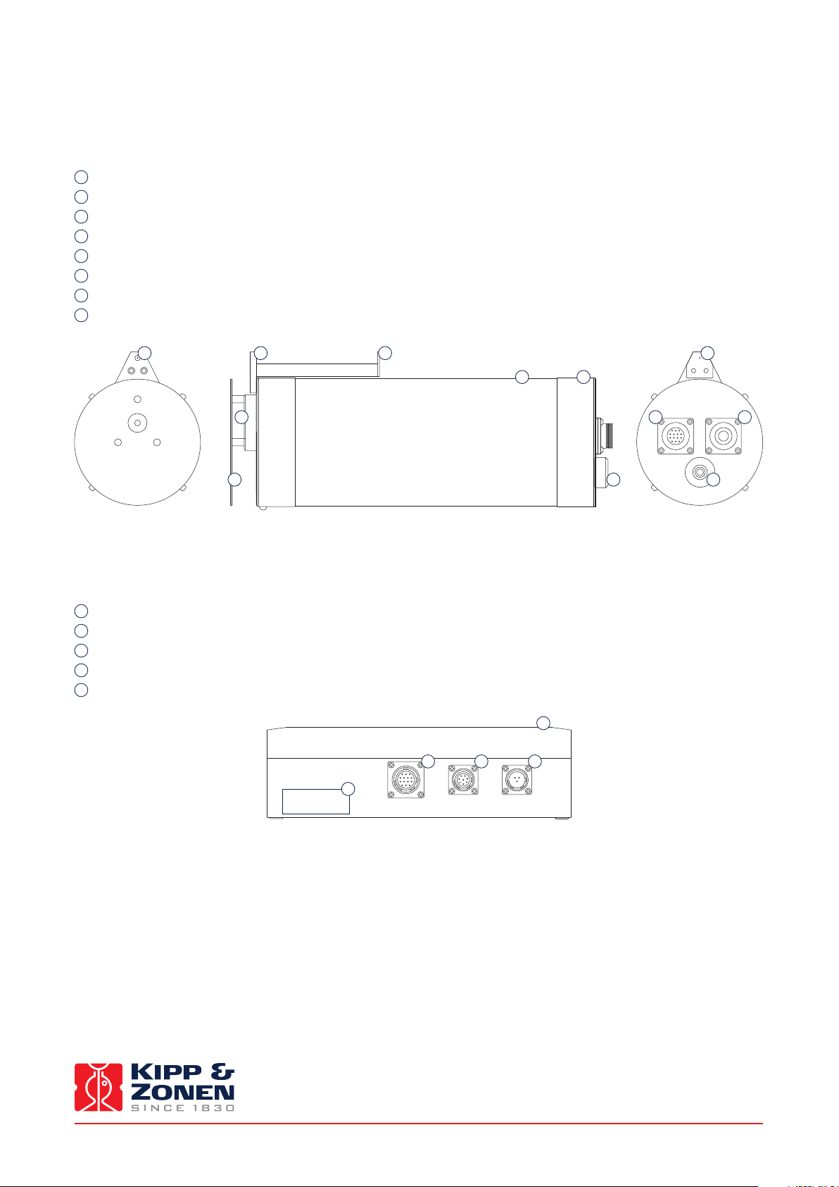
1.3 Key parts of the PGS-100 Sun Photometer
1.3.1 The radiometer
The drawing below shows the key parts of the radiometer:
1
Radiometer housing
2
Sun shield
3
Optical input window
4
Alignment aid
5
Drying cartridge
6
‘MAINTENANCE’ diagnostic socket (for factory service use only)
7
‘CONTROL A’ socket for connection to the control unit
8
Serial number label
4 4 44
1
8
3
2
1.3.2 The control unit
The drawing below shows the key parts of the control unit:
1
Control unit enclosure
2
‘CONTROL B’ socket for connection to the radiometer
3
‘PC’ socket for connection to the operating computer
4
‘POWER’ socket for connection to AC mains power
5
Serial number label
5
CONTROL B POWERPC
2 3 4
CONTROL A MAINTENANCE
7
6
55
1
Instruction Manual - PGS-100 Sun Photometer
8
Page 9

2. Installation
.
Please follow the instructions in this section carefully for the mechanical and electrical installation of the PGS-100 Sun Photometer.
Do not turn on power to the instrument until instructed to do so.
Note Do not connect the instrument to a computer until instructed to do so.
Note Do not turn on power to the operating computer until instructed to do so.
2.1 Included with the product
Check the contents of the shipment for completeness (see below) and note whether any damage has occurred during transport.
If there is damage, a claim should be filed with the carrier immediately. In the case of damage and/or the contents are incom-
plete, contact your local Kipp & Zonen representative or e-mail the Kipp & Zonen customer and product support department at:
support@kippzonen.com
The following items are included with the PGS-100 Sun Photometer:
1
The radiometer
2
The control unit
3
Connection cables
4
CD-ROM
5
Mounting rings
2.1.1 The radiometer
The radiometer contains the optical input system, solid state spectrometer with a CCD detector array, associated electronics and
temperature stabilisation components. It has a white heat shield to reduce heating by direct solar radiation, an alignment aid
for pointing the radiometer at the sun, and sockets for factory maintenance and the cable connection to the control unit. A
drying cartridge is fitted to absorb internal moisture and to prevent internal condensation that would damage the spectrometer
and optical system.
The radiometer is powered by low voltage supplied from the control unit.
Instruction Manual - PGS-100 Sun Photometer
9
Page 10
.
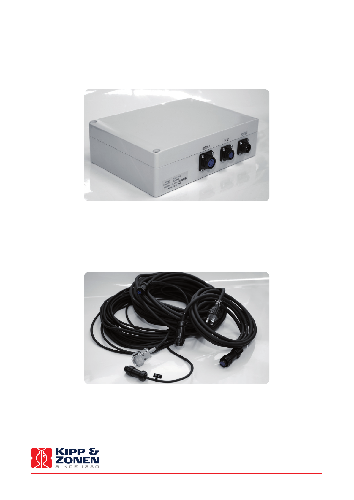
2.1.2 The control unit
The control unit is contained in a weatherproof enclosure. It contains power supplies, control circuits for the radiometer
temperature stabilization, interfaces to the radiometer and communication circuitry for a computer to operate the instrument.
2.1.3 Connection cables
Three cables are supplied with the PGS-100.
One is for connection between the radiometer and the control unit.
The second is for the supply of mains AC power to the control unit.
The third is for communication between the control unit and the operating computer.
Instruction Manual - PGS-100 Sun Photometer
10
Page 11
.
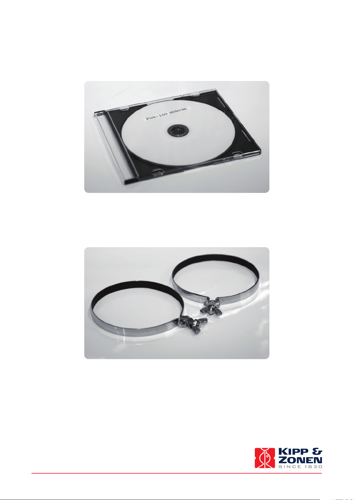
2.1.4 CD-ROM
The CD-ROM disk contains the operating software for the PGS-100 and necessary setup files.
2.1.5 Mounting rings
The radiometer is normally supplied with two mounting rings that are used for fitting it to a Prede sun tracker. These are not
required for fitting to a Kipp & Zonen sun tracker, with the PGS-100 Mounting Kit, and can be discarded.
Note A computer is not part of the PGS-100 delivery.
Instruction Manual - PGS-100 Sun Photometer
11
Page 12
2.2 Tools required
The tools required to fit the PGS-100 radiometer to a Kipp & Zonen sun tracker are supplied with the PGS-100 Mounting Kit.
2.3 Location and support base
The location requirements are the same as for any instrument designed to be mounted on an automatic sun tracker for the
measurement of direct solar radiation. The radiometer should have an unobstructed view of the sun throughout the complete
solar arc at all times of the year.
The base support for the sun tracker must be rigid and stable and the alignment must be unaffected by weather and environmental
effects. If this is not possible, the sun tracker must be fitted with an active tracking sun sensor to compensate for movements of
the base support.
The field of view and slope angle of the PGS-100 radiometer input optics require that it must be aligned on the axis of the sun
with a pointing accuracy of 0.2 ° or better.
The ambient operating temperature range of the PGS-100 is from -10 °C to +45 °C. For operation over the range from -30 °C to
+45 °C the Low Temperature Option is required. For operation over the range from -10 °C to +60 °C the High Temperature Option
is required. Please note that both options cannot be fitted at the same time.
2.4 Mounting
It is assumed that the PGS-100 radiometer is to be fitted to a Kipp & Zonen automatic sun tracker using the optional PGS-100
Mounting Kit.
2.4.1 Mounting rings
The radiometer is normally supplied with two mounting rings (shown in 2.1.5) that are used for fitting it to a Prede sun tracker.
These are not required for fitting to a Kipp & Zonen sun tracker, with the PGS-100 Mounting Kit, and can be discarded.
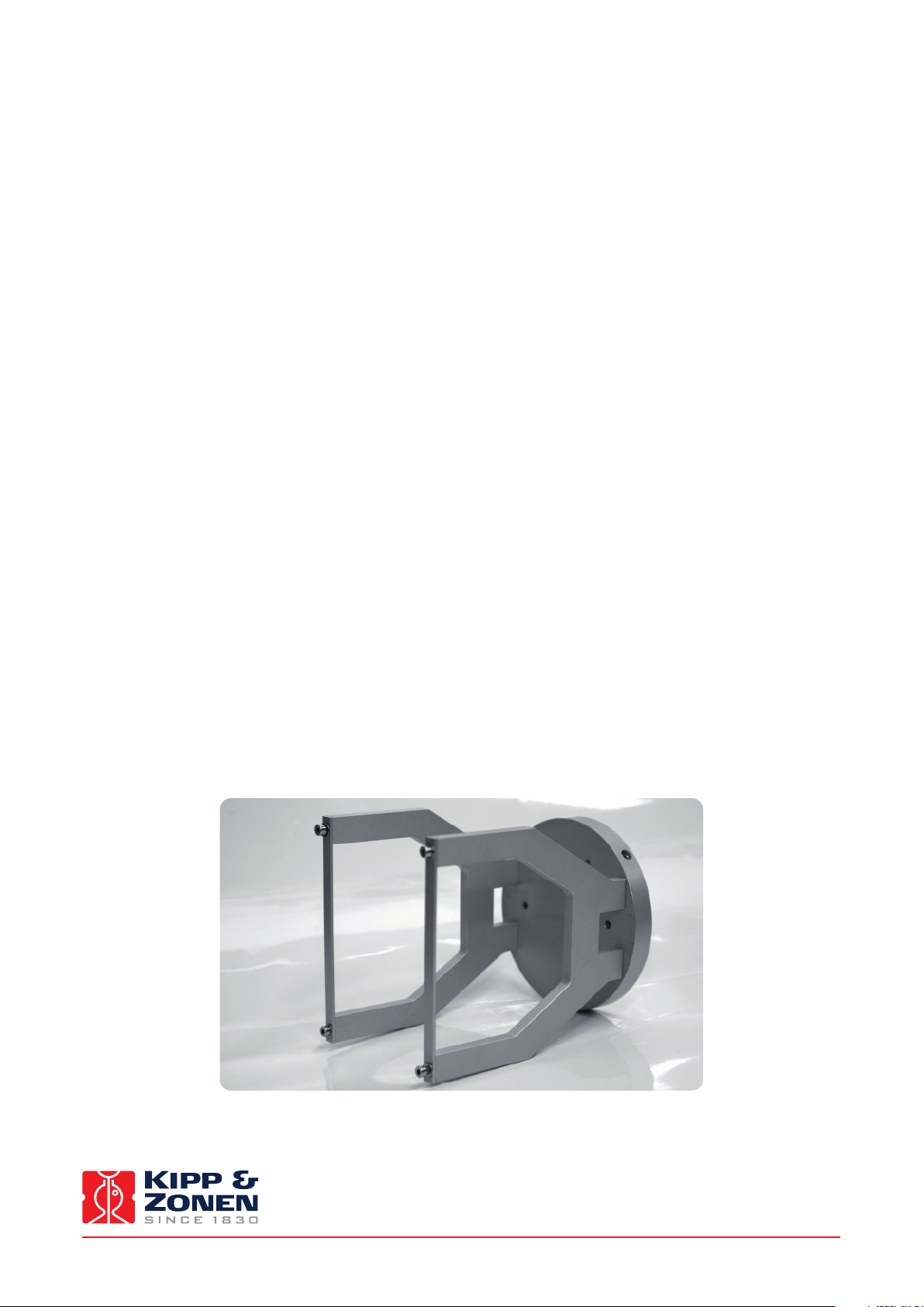
2.4.2 PGS-100 mounting kit
The mounting kit comprises two brackets, clamps, and fixings; to be fitted to a side mounting plate of a Kipp & Zonen sun tracker.
Depending upon the sun tracker configuration, a side mounting plate may also be required.
Instruction Manual - PGS-100 Sun Photometer
12
Page 13

.
The components of the mounting kit are shown below (the side mounting plate is not included).
M4x20 flat head screw (4x)
Side Mounting Plate
PGS-100 mounting clamp (2x)
PGS-100 clamp (2x)
M4x10 cap screw (4x)
M4 lock washer (4x)
M4 flat washer (4x)
2.4.3 Fitting the PGS-100 radiometer
Fit the PGS-100 radiometer into the two mounting kit brackets with the connectors at the back and the alignment aid at the top.
Secure the radiometer firmly with the two clamps such that it is centralised in the brackets, as shown below for a SOLYS 2 sun
tracker (the side mounting plate is not included in the kit).
Instruction Manual - PGS-100 Sun Photometer
13
Page 14

.
2.4.4 Alignment of the PGS-100 radiometer
Follow the sun tracker instructions for correct installation and setup.
Adjust the sun tracker and/or PGS-100 radiometer alignment such that sunlight will penetrate the first alignment hole and
create a small spot of light around the second alignment hole.
When the spot of light is fully covering the second alignment hole, the PGS-100 is correctly aligned.
2.5 Electrical connections
The plugs and sockets used in the PGS-100 are military-type circular locking connectors. Insert the plugs (they only fit in one
orientation) and screw the locking rings finger-tight. Do not over-tighten the locking rings, this may damage the waterproof seals.
The electrical connection schematic drawing is shown below:
CONTROL A
MAINTENANCE
CONTROL B POWERPC
Instruction Manual - PGS-100 Sun Photometer
14
Page 15

.
2.5.1 Connecting the radiometer to the control unit
Connect the cable with plugs labeled ‘CONTROL A’ and ‘CONTROL B’ to the radiometer socket ‘CONTROL A’ and the control unit
socket ’CONTROL B’.
2.5.2 Connecting the control unit to power
Connect the cable labeled ‘POWER’ to the control unit socket ‘POWER’ and to the AC mains outlet.
The control unit can operate from 115 or 230 VAC, 50 Hz or 60 Hz, and has a maximum power consumption of 30 W.
If there is doubt about the quality or reliability of the AC mains power an Uninterruptable Power Supply (UPS) should be used
for the computer and the PGS-100.
The PGS-100 power cable has a protective earth wire that must be connected to a secure ground point at the AC
power outlet. This provides electrical safety, protection against lightning-induced damage (not direct strikes), and
forms part of the EMC / RFI shielding.
Do not turn on power to the instrument at this point.
2.5.3 Connecting the control unit to the operating computer
Connect the cable labeled ‘PC’ to the control unit socket ‘PC’ and to the to the RS-232C serial port of the operating computer, or
to a RS-232 to USB converter from a reputable manufacturer if a serial port is not available.
Note Ensure that any RS-232 to USB converter has the appropriate driver for the computer operating system installed,
and is operating correctly.
2.5.4 Computer requirements
PGS-100 must be connected to a computer running the supplied operating software in order for the instrument to make measurements
and to store the spectral data. A computer is not part of the PGS-100 delivery.
The operating software supplied with the PGS-100 has been developed to operate in a Windows™ 32-bit environment only. It
will install in a 64-bit environment, but it will not communicate with the PGS-100. The software will operate correctly with
Windows™ 2000, Windows™ XP and Windows™ 7, 32-bit versions. Use of any version of Windows™ Me or Windows™ Vista is
unreliable and not recommended.
Normally the PGS-100 and its operating software are running continuously, 24 hours per day and 7 days per week. Therefore, it
is recommended to use a desk-top computer designed for 24/7 operation, rather than a laptop computer.
The communication to and from the PGS-100 is by RS-232. Most desk-top computers have a ‘legacy’ serial port with screw-lock
9-pin connector and this is the preferred type of connection. If a RS-232 port is not available ensure that any RS-232 to USB
converter has the appropriate driver for the computer operating system installed, and is operating correctly. Unbranded,
generic, converters often exhibit communication problems.
The data files are not large, so processor speed and memory capacity of the computer are not important issues.
Instruction Manual - PGS-100 Sun Photometer
15
Page 16

Instruction Manual - PGS-100 Sun Photometer
16
Page 17

3. Accessories
.
There are two accessories available for the PGS-100 to extend the standard ambient operating, which is from -10 °C to +45 °C.
Please note that both options cannot be fitted at the same time.
3.1 Low temperature option
For operation over the range from -30 °C to +45 °C the Low Temperature Option is required. This consists of an insulated cover
for the radiometer. Fitting instructions are included with the option.
3.2 High temperature option
For operation over the range from -10 °C to +60 °C the High Temperature Option is required. This consists of reflective heat
shields for the radiometer and a cooling ring which has liquid circulating through an AC mains powered chiller unit. Fitting and
maintenance instructions are included with the option.
Instruction Manual - PGS-100 Sun Photometer
17
Page 18

Instruction Manual - PGS-100 Sun Photometer
18
Page 19

4. Software Installation and Configuration
.
The operating software for the PGS-100 Sun Photometer is supplied on a CD-ROM. The operating computer must be running on
a 32-bit version of Windows™ XP or Windows™ 7.
4.1 Installing the software
1. Insert the supplied CD into the CD/DVD ROM drive of the operating computer. There will be a folder named ‘PGS100’ and with
the serial number of the radiometer in the name.
2. Open this folder.
Note The manual in the folder is the original Prede version and not this Kipp & Zonen manual.
3. Open the PGS-100 software folder and browse through version, and setup_language folders until you reach the file ‘setup.exe’.
4. Double click on ‘setup.exe’ to start installation of the software on your computer.
5. Press ‘OK’ at the first screen.
6. Press the large install button at the next screen. It is not recommended to change the installation directory to an external drive.
7. Press ‘Continue’ at the next screen. It is not recommended to change the Program Group.
A message will appear that the software was successfully installed.
8. Press ‘OK’.
Note Do not start the software yet.
Instruction Manual - PGS-100 Sun Photometer
19
Page 20

.
9. Browse the CD again and copy the folder ‘wavelength file’ into the installation directory.
The default location is c:\Program Files\PGS100_verxxxxxx
10. In Windows™ XP the folder should now look as below:
11. In Windows™ 7 the folder should now look as below:
Instruction Manual - PGS-100 Sun Photometer
20
Page 21

.
12. Open the ‘wavelength file’ folder and check the name of the wavelength file. It should be a text file with no capital letters,
for example ‘10542a.txt’
Note It is also recommended to copy the ‘PGS-100 calibration constant’ folder from the CD-ROM to this installation
directory for future reference.
13. Remove the CD-ROM from the drive.
It is recommended to turn off the computer and then turn it on again to ensure that the software installation is complete.
14. Store the software CD-ROM in a safe place in case it is needed to reinstall the software, or use it on another computer, in the future.
4.2 Configuring the software
The operating software executable with the ‘sun’ symbol will now appear in the Start Menu in ‘Programs’. This is
‘PGS100_ver317ENG in the example of 4.1 step 9. For ease of use it is recommended to make a shortcut to this application and
place it on the desktop.
1. Double click on the executable and the program will start.
A message will pop up saying ‘A wavelength file does not exist’ - this is normal because the software is not configured yet.
2. Press’OK’. The screen shown below will appear.
3. Press the ‘STOP’ button before the count down reaches 0 seconds.
Pressing the ‘START’ button or waiting for the countdown to time out will start measurement according to the configuration
settings (not done yet). Pressing ‘EXIT’ will close the program.
A message will pop up saying ‘Serial port COM1. It cannot open’ - this is normal because the software is not configured yet.
4. Press’OK’. Now the main screen will appear.
Instruction Manual - PGS-100 Sun Photometer
21
Page 22

.
On this screen you can see information of the time, status, and some other settings that are currently active. The ‘START’ button
will activate timed measurements according to the predefined settings (not done yet), the ‘STOP’ button will only be active after
the measurement has started. The ‘ONE SHOT’ button activate a single instantaneous measurement. The ‘CONFIG’ button opens
the configuration screen of the software.
The lower half of the screen shows an overview of the measurement periods and the graphical display of the last measurement.
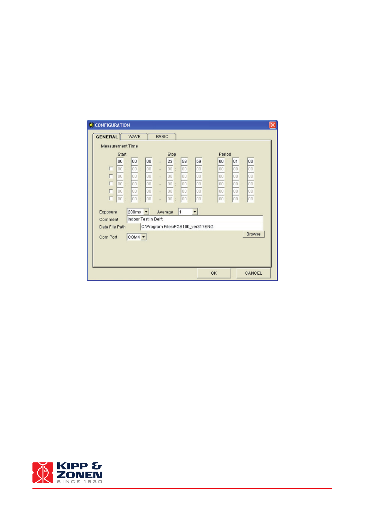
5. Press the ‘CONFIG’ button to open the screen below.
6. Set the Exposure time to 200 ms and the Average to 1, in order to get started.
A Comment can be added, for example the instrument location. Do not change the Data File Path at this time.
7. Select the appropriate COM Port number to suit the RS 232 or USB connection to the PGS-100.
8. Select the ‘WAVE’ tab. All the fields should be empty.
9. Select the ‘BASIC’ tab. And configure the settings as shown below.
Instruction Manual - PGS-100 Sun Photometer
22
Page 23

.
10. For the Wave File Path, browse to the installation directory into which you copied the folder ‘wavelength file’. The default
location is c:\Program Files\PGS100_verxxxxxx.
11. Select the ‘wavelength file’ folder, and click on ‘Open’.
12. Select the ‘txt’ file, and click on ‘Open’. The location will now appear as the Wave File Path.
13. For Offset the default value is ‘27’. This only applies to older PGS-100 radiometers. Change this to ‘0’.
14. Select ’Length’, for the Data Save Direction. If ‘Width’ is used, some spreadsheets may run out of columns.
15. Select ‘csv’, for the Data File Attribute, to easily export the data to spreadsheets.
16. Enter ‘240’, for Maximum Data.
When the number of measurements exceeds 240 a new file will be created. If the field is left empty (blank) the number of
measurements is not limited and a new file will be created each day at midnight.
17. The default Data Rate is 19200 baud. However, for some of the faster modern computers this rate (and 9600 baud) is too
slow for reliable communication. It is recommended to select 38400 baud.
18. The Receive Buffer Size cab remains at 32 KB.
Instruction Manual - PGS-100 Sun Photometer
23
Page 24

.
19. Move the Performance slider to the highest setting. This is not a problem for modern computers.
The screen should now look as in step 9.
20. Press the ‘OK’ button. The main screen will appear showing the modified settings.
21. Press the ‘GRAPH’ button and change the settings as below. These should be sufficient to start measurements with direct
sunlight, the graph can be rescaled later, if necessary.
22. Press ‘OK’. The main screen will appear as below.
The default Measurement Time will configure as from midnight to midnight each day and with a Measurement Period (interval)
of 1 minute.
The software is now fully configured and the program should be closed.
Instruction Manual - PGS-100 Sun Photometer
24
Page 25

5. Operation and Measurement
.
The radiometer of the PGS-100 is temperature controlled at +35 °C ± 2 °C to maintain the wavelength stability and the sensitivity
of the detector in the spectrometer. Therefore, the PGS-100 should normally be continuously switched on to avoid a warm-up
time before the control temperature is reached.
The operating software can be started and stopped with the PGS-100 switched on and connected to the computer. The software
can be started first and then the PGS-100 switched on, but there may be a warm-up time before full accuracy is achieved, as
mentioned above.
Note Turning the PGS-100 off, or disconnecting the ‘PC’ cable, whilst the software is running may cause the hardware
and/or software communication drivers to hang up. In this case it will be necessary to restart the software and
maybe also to restart the computer. Close the software before turning off the PGS-100 or disconnecting the ‘PC’ cable.
5.1 Starting measurement
As mentioned previously the PGS-100 should be already switched on and warmed up.
1. Start the software.
2. In the opening screen, either press the ‘START’ button or wait for the 10 second timer to count down to 0 seconds.
The main screen will appear showing the time to the next measurement. At that time the PGS-100 will make a measurement and
the result will be displayed on the graph as shown below (the example spectrum is for a tungsten-halogen lamp) and stored to
the computer disk. The intensity of the radiation received is given in ‘Counts’. These are arbitrary units, the measured spectrum
shows the relative intensity of the radiation received at different wavelengths.
Instruction Manual - PGS-100 Sun Photometer
25
Page 26

.
A second, small, window opens after each measurement showing the main parameters, including the radiometer internal
temperature and the current cursor position.
The graph can be rescaled to suit the current conditions without affecting the data that is stored. The graph only displays the
last measurement. The red cursor line can be moved using the mouse pointer to any point on the x-axis and the corresponding
wavelength and intensity can be read in the small window.
Each time the radiometer makes a measurement a ‘click’ can be heard. This is the exposure shutter operating, as in a camera.
5.2 Averaging and exposure time
As can be seen in 5.1 step 2, when the light intensity is low and a short exposure time is used (200 ms) with a single measurement
the result can be quite noisy. In the ‘GENERAL’ configuration window the number of ‘shots’ to be averaged can be selected. The
screenshot below shows the effect of averaging 50 shots of 200 ms exposure.
The intensity is not affected, but the noise is significantly reduced. However, when measuring natural sunlight, if too many
averages are made the atmospheric conditions may be changing during the process.
Instruction Manual - PGS-100 Sun Photometer
26
Page 27

.
It is also possible to alter the exposure time. This will, of course allow more light into the spectrometer and increase the
measured intensity and also reduce noise, as shown below.
To stay within the linear range of the detector array, the number of counts should not exceed 10000.
Instruction Manual - PGS-100 Sun Photometer
27
Page 28
5.3 Measurement time and period
The default Measurement Time will configure as from midnight to midnight each day and with a Measurement Period (interval)
of 1 minute. However, this can be changed in the ‘GENERAL’ configuration window.
Up to six Measurement Times can be set with Start and Stop in hours, minutes and seconds. These must follow in chronological
sequence and must not overlap (allow sufficient time for any averaging of the final measurements to be completed). Each of
these Times can have its own Measurement Period in hours, minutes and seconds and each can be activated or deactivated by
ticking or un-ticking the associated box to the left.
Instruction Manual - PGS-100 Sun Photometer
28
Page 29

5.4 Waveband selection
By default the ‘WAVE’ configuration window is left empty and the complete spectrum is saved for each measurement. As disk
capacity is not a problem with modern computers it is usually best to use this default setting.
However, it is possible to select up to 20 wavebands and only the data within these bands will be stored. These wavebands must
follow in sequence from short to long wavelengths and must not overlap.
Instruction Manual - PGS-100 Sun Photometer
29
Page 30

5.5 Log and data files
The data and log files are stored in the installation directory, the default location is c:\Program Files\PGS100_verxxxxxx.
5.5.1 Log file
The pgs100.log file is in text format and lists when measurements were made and when the software was started and stopped.
5.5.2 Measurement data files
The files are identified by date (year, month, day) and format. When there is more than one file for a day there is an extension
number ‘_n’.
It is recommended that these files are backed up regularly.
Instruction Manual - PGS-100 Sun Photometer
30
Page 31

.
An example of a data file for a ‘ONE SHOT’ measurement is shown below, with ’comment’ as the header, the main settings listed,
and the intensity counts at each wavelength. During continuous operation an additional column is created for each measurement.
Indoor Test in Delft
Date
Time
Exposure time
Number of times of an average
Temperature
07/12/2011
14:19:36
200
1
34
Wavelength
318.193
318.949
319.704
320.460
321.216
...
...
...
912.602
913.310
914.018
914.726
915.433
916.141
916.849
917.556
918.264
918.971
919.678
920.385
921.092
...
...
...
1059.393
1060.075
1060.757
1061.439
1062.120
1062.802
1063.483
1064.165
S1_CH1
4
-35
-9
-27
-17
...
...
...
823
889
801
829
813
804
812
805
815
805
799
819
805
...
...
...
175
165
162
156
163
164
130
162
Instruction Manual - PGS-100 Sun Photometer
31
Page 32

.
5.5.3 Calibration data file
The CD-ROM contains a folder named ‘PGS-100 calibration constant’. In this folder is an excel file containing the calibration
information for the specific PGS-100 radiometer (the serial number is in the file name).
This ‘Calibration Constant’ file gives the sensitivity of the radiometer at each wavelength in the range from just below 350 nm
to just beyond 1050 nm. The sensitivity is in units of W/m²/µm/Count and can be used to convert the ‘counts’ in the measured
data file into the direct solar irradiance in W/m²/µm.
Note There is no software for analysis of the data recorded from the PGS-100 Sun Photometer. It is for the user to
perform data analysis to suit their particular application.
Because of the narrow field of view it is very difficult to calibrate instruments such as the PGS-100 Sun Photometer in a laboratory.
They are best calibrated outdoors against a reference spectro-radiometer, at close to solar noon on a clear day with low aerosol
content in the atmosphere.
A new PGS-100 is calibrated on the roof of the Prede Co. Ltd. Facility in Tokyo, by comparison to a reference PGS-100 which has
been calibrated either at the NOAA Mauna Loa Observatory in Hawaii or at the National Renewable Energy Laboratory (NREL) in
Golden, Colorado.
Instruction Manual - PGS-100 Sun Photometer
32
Page 33

6. Maintenance and Re-calibration
.
The PGS-100 is simple to maintain and does not require any special tools or training. There are no service items requiring
scheduled replacement.
6.1 Weekly maintenance
Clean the optical window at the front or the radiometer using pure alcohol or distilled water and a lint-free cloth. Ensure that no
smears or deposits are left on the window.
Check the alignment of the radiometer to the sun, and adjust if necessary (refer the sun tracker manual).
6.2 Monthly maintenance
Check the desiccant in the drying cartridge on the rear of the radiometer. This is a self-indicating silica-gel. When it requires
replacement the colour changes from blue to pink, or from orange to clear (depending upon the type used).
Note The blue type of silica gel contains Cobalt salts and it is not allowed to be used in the European Union under health
and environmental legislation.
To replace the desiccant unscrew the cartridge from the radiometer housing, remove the cap in the end of the tube and safely
dispose of the used silica-gel. Refill with fresh desiccant, replace the end cap in the tube. Make sure that the o-ring seal and its
seat in the housing are clean. Screw in the drying cartridge hand-tight only to avoid distorting the o-ring seal.
6.3 Yearly maintenance
Check all the electrical connections. Unscrew the plugs, clean the contacts if necessary and then reconnect.
Check cables for damage caused by accident or by rodents.
Check the instrument mountings and any base supports are secure.
6.4 Calibration
The PGS-100 is a very stable instrument. However, a re-calibration is recommended every two years. The calibration method is
outlined in section 5.5.3 and it is unlikely that the user has the necessary reference equipment to perform a calibration.
Therefore, it is usually necessary to return the PGS-100 to the Prede Co. Ltd. Factory in Tokyo for re-calibration, or to another
facility with suitable reference equipment.
Instruction Manual - PGS-100 Sun Photometer
33
Page 34

Instruction Manual - PGS-100 Sun Photometer
34
Page 35
7. Specifications
.
Kipp & Zonen and the manufacturer, Prede Co. Ltd., reserve the right to make changes to specifications and other product
documentation without prior notice.
7.1 Optical and electrical
Detector Silicon CCD array, 2048 elements
Minimum exposure time 200 ms
Nominal wavelength range 350 nm to 1050 nm
Slit width 100 µm
Wavelength accuracy ± 0.5 nm
Half-power bandwidth 3.6 nm
Full opening view angle 2 °
Slope angle 0.5 °
Supply voltage: 115/230 VAC, 50/60 Hz
Maximum power consumption 30 W
Operating temperature range - 10 °C to + 45 °C
- 30 °C to + 45 °C with low temperature option
- 10 °C to + 60 °C with high temperature option
Radiometer stabilization temperature + 35 °C ± 2 °C
Communication RS-232C serial
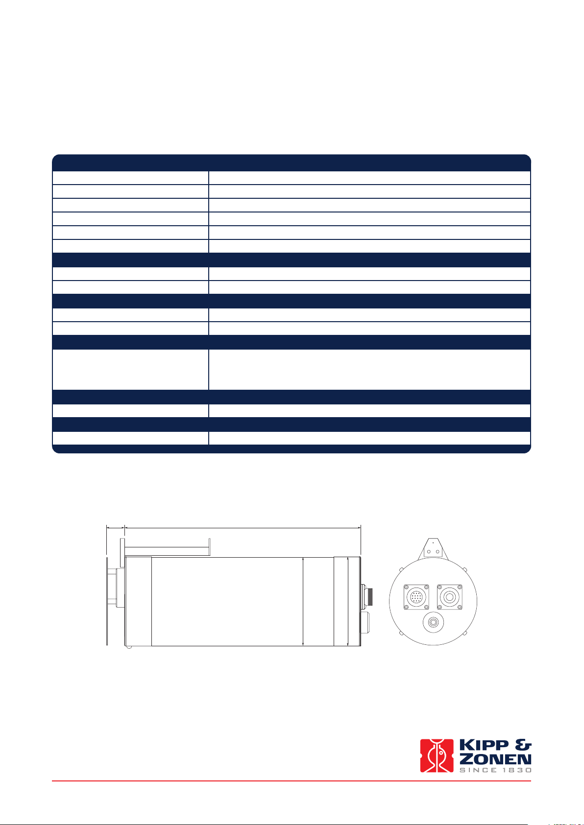
7.2 Dimensions and weight
Drawing of radiometer (in mm).
21.5 280
105
106
CONTROL A
MAINTENANCE
Weight: 2.5 kg
Instruction Manual - PGS-100 Sun Photometer
35
Page 36

.
Drawing of control unit (in mm).
250
17574
Weight: 1.5 kg
CONTROL B POWERPC
Instruction Manual - PGS-100 Sun Photometer
36
Page 37

8. Trouble shooting
.
There are no user-serviceable parts within the radiometer and it must not be opened without the agreement and
instruction of Kipp & Zonen or Prede Co. Ltd.
The control unit is AC mains powered and therefore contains a risk of shock if opened. The control unit must not
be opened without the agreement and instruction of Kipp & Zonen or Prede Co. Ltd.
Most problems with the PGS-100 Sun Photometer after a successful installation are related to communication problems
between the instrument and the computer, often due to power interruptions or disconnecting cables whilst the operating
software is running.
If this occurs, check that the port number is still correct. Close the software and turn off the computer. Turn off the power to the
PGS-100 and disconnect the ‘PC’ cable.
Reconnect the ‘PC’ cable and turn on the power to the PGS-100. Wait a few minutes and turn on the computer. Restart the
operating software.
In an extreme, but unlikely, case it may be necessary to reinstall the operating software. Back up all the measurement data files
before reinstallation.
If the measured radiation intensity appears to be low for the prevailing conditions check that the optical window is clean and
check the alignment of the radiometer to the sun, and adjust if necessary.
If the measured radiation intensity is close to zero and radiation is available, check that the radiometer shutter is operating.
The shutter should make a ‘click’ when it operates. For help regarding this, or other problems, please contact Kipp & Zonen
customer support.
Instruction Manual - PGS-100 Sun Photometer
37
Page 38

Instruction Manual - PGS-100 Sun Photometer
38
Page 39

9. Customer Support
.
If you require any support for your Kipp & Zonen product please contact your local representative in the first instance. The
information can be found in the ‘Contact’ section of our website at http://www.kippzonen.com/?page/74152/Contact.aspx
Alternatively, you can contact us directly at www.kippzonen.com/support
Please include the following information:
• Instrument model
• Instrument serial number
• Details of the fault or problem
• Examples of data and log files
• Latest valid calibration file
• Computer type and operating system
• Interfaces, power supplies and sun tracker used in the installation
• History of any previous repairs or modifications
• Pictures of the installation and site
• Overview of the local environment conditions
Kipp & Zonen guarantees that your information will not be shared with other organisations.
Instruction Manual - PGS-100 Sun Photometer
39
Page 40

Our customer support remains at your disposal for any maintenance or repair, calibration,
supplies and spares.
Für Servicearbeiten und Kalibrierung, Verbrauchsmaterial und Ersatzteile steht Ihnen unsere
Customer Support Abteilung zur Verfügung.
Notre service 'Support Clientèle' reste à votre entière disposition pour tout problème de
maintenance, réparation ou d'étalonnage ainsi que pour les accessoires et pièces de rechange.
Nuestro servicio de atención al cliente esta a su disposición para cualquier actuación de
mantenimiento, reparación, calibración y suministro de repuestos.
HEAD OFFICE
Kipp & Zonen B.V.
Delftechpark 36, 2628 XH Delft
P.O. Box 507, 2600 AM Delft
The Netherlands
T: +31 (0) 15 2755 210
F: +31 (0) 15 2620 351
info@kippzonen.com
SALES OFFICES
Kipp & Zonen France S.A.R.L.
88 Avenue de l’Europe
77184 Emerainville
France
Kipp & Zonen Asia Pacific Pte. Ltd.
10 Ubi Crescent Lobby E
#02-93 Ubi Techpark
Singapore 408564
Kipp & Zonen USA Inc.
125 Wilbur Place
Bohemia
NY 11716
United States of America
Go to www.kippzonen.com for your local distributor or contact your local sales office
T: +33 (0) 1 64 02 50 28
F: +33 (0) 1 64 02 50 29
kipp.france@kippzonen.com
T: +65 (0) 6748 4700
F: +65 (0) 6748 6098
kipp.singapore@kippzonen.com
T: +1 (0) 631 589 2065
F: +1 (0) 631 589 2068
kipp.usa@kippzonen.com
Passion for Precision
 Loading...