

Page 1
METEON 2.0
Instruction Manual
Page 2

2
1 Declaration of Conformity
Page 3

3
2 Contents
1 Declaration of Conformity .................................................................................................................. 2
2 Contents ............................................................................................................................................. 3
3 NOTES ................................................................................................................................................. 5
4 Introduction ........................................................................................................................................ 6
5 METEON function overview ............................................................................................................... 6
5.1 Front view ................................................................................................................................... 6
5.2 Top view ..................................................................................................................................... 7
6 Meteon connections .......................................................................................................................... 7
6.1 DC IN ........................................................................................................................................... 7
6.2 Analog ......................................................................................................................................... 7
6.3 Pulse ........................................................................................................................................... 7
6.4 Modbus ....................................................................................................................................... 9
6.5 Batteries ................................................................................................................................... 10
6.6 Supplied parts ........................................................................................................................... 10
7 Specifications .................................................................................................................................... 11
8 Power consumption ......................................................................................................................... 12
9 Memory usage .................................................................................................................................. 12
10 Menu structure overview ............................................................................................................. 13
11 Keyboard functions ..................................................................................................................... 14
12 Operation mode ........................................................................................................................... 15
12.1 PC communication.................................................................................................................... 15
12.2 Transparent .............................................................................................................................. 15
13 Configuration ................................................................................................................................ 15
13.1 Modbus setting ......................................................................................................................... 15
13.2 Pulse input ................................................................................................................................ 16
13.3 Temperature sensor ................................................................................................................. 16
13.4 Analog sensor ........................................................................................................................... 16
13.5 Smart sensor ............................................................................................................................. 16
14 Measurement ............................................................................................................................... 16
14.1 Measurement without logging ................................................................................................. 16
14.2 Logging ..................................................................................................................................... 16
Page 4

4
14.3 Differential Measurement ........................................................................................................ 16
15 Device setting ............................................................................................................................... 17
16 PC software .................................................................................................................................. 18
16.1 Start Screen .............................................................................................................................. 19
16.2 Data Explorer screen ................................................................................................................ 20
16.3 Preferences screen ................................................................................................................... 21
16.4 Sensor list ................................................................................................................................. 22
16.5 Update METEON ....................................................................................................................... 22
Page 5

5
3 NOTES
Reading this entire manual is recommended for a full understanding of this product.
The exclamation mark within an equilateral triangle is intended to alert the user to the presence of
important operating and maintenance instructions in the literature accompanying the instrument.
Kipp & Zonen reserve the right to make changes in the specifications without prior notice.
3.1 WARRANTY AND LIABILITY
Kipp & Zonen guarantees that the product delivered has been thoroughly tested to ensure that it
meets its published specifications. The warranty included in the conditions of delivery is valid only if
the product has been installed and used according to the instructions supplied by Kipp & Zonen. This
product is under warranty for 24 months from the date of purchase.
Modifications made by the customer or on customer request can affect the validity of the CE
declaration.
Kipp & Zonen shall in no event be liable for incidental or consequential damages, including without
limitation, lost profits, loss of income, loss of business opportunities, loss of use and other related
exposures, however caused, arising from the faulty and incorrect use of the product.
COPYRIGHT 2019 Kipp & Zonen
All rights reserved. No part of this publication may be reproduced, stored in a retrieval system or
transmitted in any form or by any means, without permission in written form from the company.
In the case you have questions, comments or need technical support, please contact us at the
following address:
Kipp & Zonen B.V.
Delftechpark 36
2628 XH Delft
the Netherland
+31 15 2755 234
support@kippzonen.com
www.kippzonen.com
Page 6

6
4 Introduction
The METEON 2.0 is a compact handheld data logger specialized for PV related Solar Radiation
measurement. It is supplied in a small carrying case that has also room for a pyranometer with cable. It
accepts simultaneously up to 5 Smart and one analog Kipp & Zonen pyranometers plus a Mencke &
Tegtmeyer PV panel temperature sensor. An S0 input / output for kWh meter or Inverter pulses and an
USB port are present. The large 8 x 22 character display is readable in full sunlight and has back light
for low light conditions. The keypad with 7 keys can be used to navigate through the different menus.
When using the UBS connection the METEON 2.0 can be set in transparent mode to act as a universal
RS-485 interface for the connected Modbus sensors. The Internal batteries (5 x AA) provide the
METEON and the Smart radiometers with power. For a M&T temperature sensor an external power
supply (12 VDC) has to be connected. The Meteon can measure, display and log up to 8 devices.
Depending on the log interval it logs up to weeks of data. Comparison of pyranometers is possible with
one as reference instrument. Log files are transferred to the PC via the USB interface. Log data can be
visualized and/or exported to a csv file with the free available software. Instruments, time and settings
are copied in the header of each file.
5 METEON function overview
The following functions are available in the Meteon.
Setting of Modbus radiometer communication parameters
Setting of METEON communication and logging parameters
Connection of up to 5 Smart and one analog radiometer
Connection of M&T temperature sensor and kW pulses
Display of measured values on screen
Logging of measured values and transfer to PC
Comparison of 2 pyranometers (DUT and a reference instrument)
Transparent mode, to act as a RS-485/Modbus to USB converter
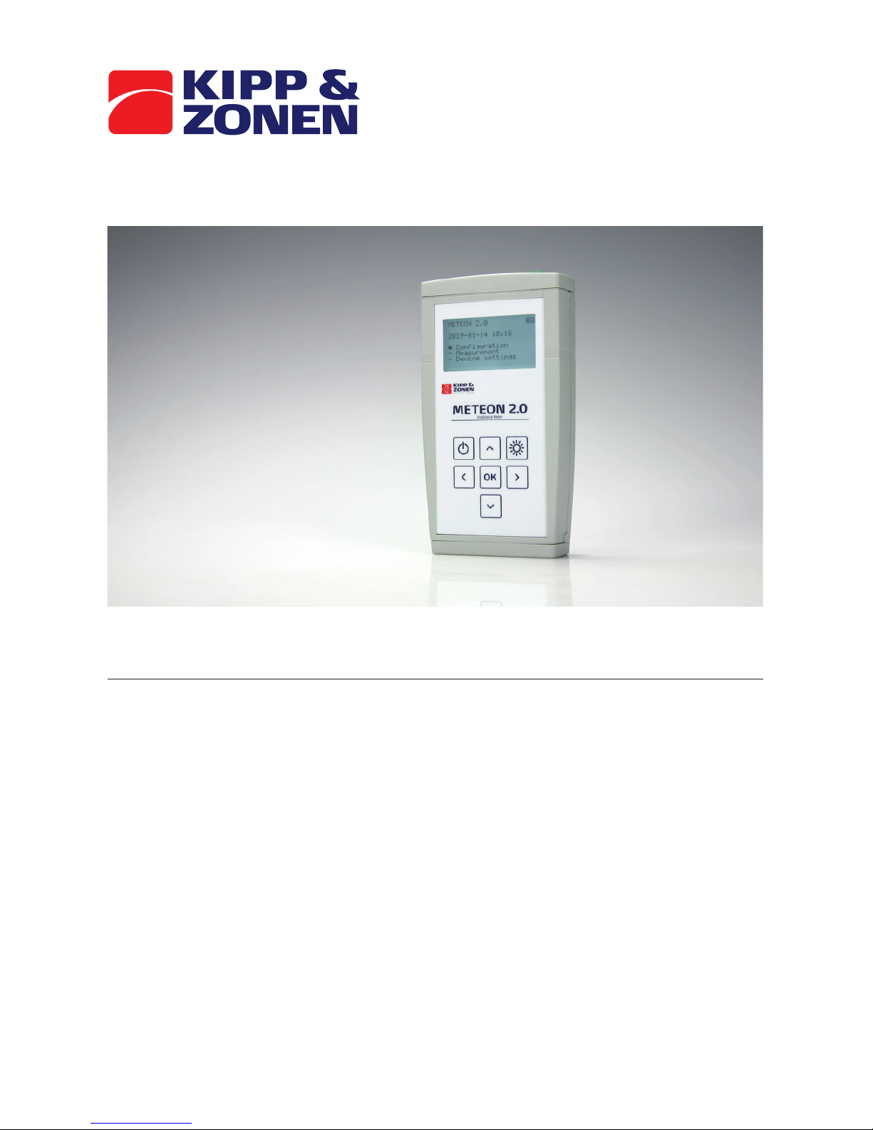
5.1 Front view
Display 8 x 22 characters with backlight or sunlight view
Keypad with 7 keys with tactile feedback (see keyboard and functions)
Knobs to release the battery compartment latch (see section batteries)
Page 7
7
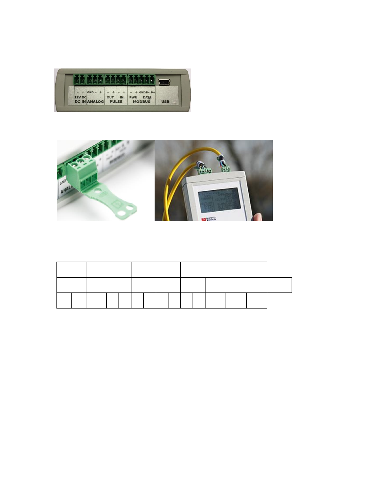
5.2 Top view
All connection are done on the top
The provided connectors have the possibility to tie the cable to the strain relief.
6 Meteon connections
DC IN
ANALOG
PULSE
MODBUS
12 VDC
OUT
IN
PWR
DATA
USB - +
GND
- + - + - + - + GND
D-
D+
6.1 DC IN
Beside batteries the Meteon can be operated on external DC power. When using the Mencke &
Tegtmeyer temperature sensor this is a must, because it requires 12 VDC.
The DC input can accept 10 – 24 Volt DC, nominal 12 VDC. If DC power is not present or below 10 Volt,
the Meteon will switch to battery use.
6.2 Analog
Here an analog radiometer can be connected like CMP11. The GND connection can be used to connect
the shield of the radiometer cable.
6.3 Pulse
The pulse input connection to relate the incoming radiation to the generated electrical power can be
used when your power meter has a so called S0-output. The number of pulses per kWh can be set in
Page 8

8
the Pulse input menu. If the energy is generated by a number of PV panels, the number of square
meters of your panels can be set as well. In this way the total amount of kWh per m2 is calculated.
Because only one connection per S0 output can be made, the Meteon also as an output to connect this
to a second device, without blocking further use of the S0 port.
Physical connection
Terminal block / Inside Meteon
The S0 outputs (often called S0+, S0- or S+ and
S-) have to be connected to the Pulse input of
the Meteon. Both pulse in- and output are
optically isolated. The input can be tested by
connecting the + and – inputs to simulate an
input pulse. The picture on the left shows a
simplified schemeatic of the inside of the
Meteon.
The nominal Pulse in- and output current is 20
mA [max is 50 mA], and the opto-coupler
isolation is 5kV.
Page 9
9
6.4 Modbus
On the Modbus input multiple Modbus devices can be connected. Up to 5 Smart radiometers and a
M&T temperature sensor. Of course they have to be configured with identical communication settings
and different Modbus addresses. The Smart sensors can be powered by the Meteon 2.0 when this
option is enabled in the Configuration menu.
The Modbus Common or Ref connection is connected to the Modbus GND on the METEON
For a K&Z Smart radiometer these connections are:
METEON:
D+
D-
PWR +
PWR -
Modbus GND
Page 10
10
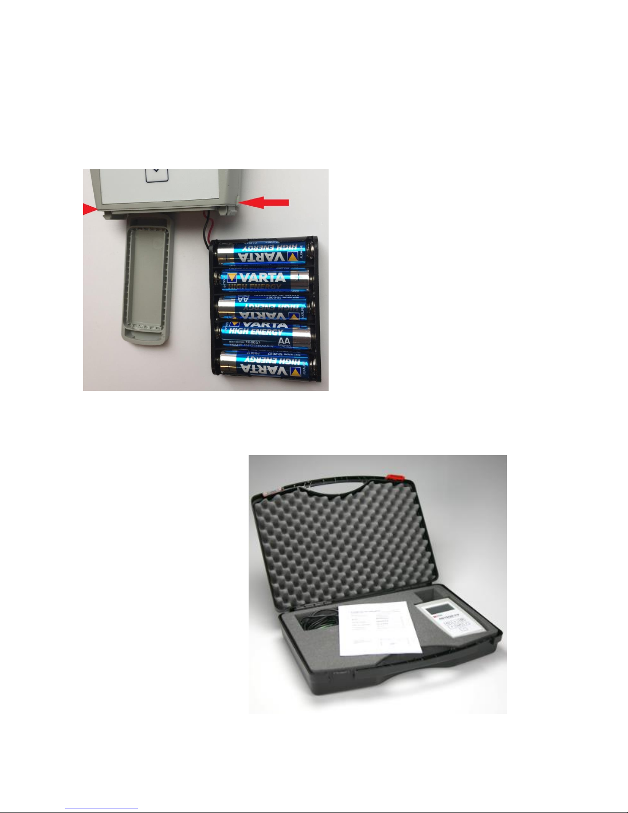
6.5 Batteries
Changing the batteries can be done by pressing the 2 buttons near the bottom on both sides of the
housing (indicated with red arrows) At the same time the lid closing the battery compartment can be
pulled off. The last battery becomes visible and the battery holder can be pulled out. Five AA alkaline
batteries are required to supply the METEON with 7.5 Volt. When batteries are replaced the holder
and lid can be pushed back in place. Make sure the lid clicks properly in place.
6.6 Supplied parts
The Meteon is supplied with
Mounted batteries (5 x AA)
A carrying case with room for a
pyranometer
A calibration certificate
Connectors for the four inputs
Mini USB cable
Page 11

11
7 Specifications
Measurement Requirements
Specification
Analog mV range full scale
Suitable for all K&Z radiometers
Analog resolution
0.1W
Basic accuracy after calibration
0.1%
Temperature sensitivity over full
temperature range
< 0.5%
Offset drift over full temp range
< 3µV
Input circuit
>2MΩ 470 nF
Sampling / filter
1s, 50 / 60 Hz filtering
Logging
1,2,5… s, min, h, aver, min, max
Modbus input
5 x Smart Sensor
RTC accuracy
5 min /y
Logging
Internal memory
Functionality
Display, logging
Up to 7 sensors
Meteon RS485 port setting
Set communication parameters
Modbus / comm. setting
Set address & comm. (per 1 dev)
Comparison & logging
2 radiation sensors
RS485 to USB
Transparent mode
Design
PC / Calibration
Via mini USB connector
Sensor connectors
Wago / Phoenix
LCD
Graphic, 8 lines of text, back light
Good sunlight readability
Keyboard
Up, Down, Left, Right, OK,
On/Off, Back Light
Batteries
5 x AA type
Battery life
>3 days, 3 sensors logging
DC connector
input for DC power supply
10 – 24 V (± 10%)
Connected instruments
Analogue
CM, CMP, CUV, SP-Lite, PQS
Modbus
SMP, SUV, SGR, SHP, PR1,
PH1, RT1, M&T
Communication
USB,
transparent mode RS-485 to USB
USB
Mini USB, opto isolated
Page 12

12
RS485
70V tolerant
TVS protection
PC Software
Dedicated PC software to:
Visualize
- Display actual sensor values
- Comparison data
- Data graph
Calibration of METEON 2.0
Export of csv data
Delivery
METEON 2.0
Carrying case with Room for 1 pyranometer
Calibration certificate
USB cable
Connectors for inputs
Environment / Testing
Temperature range operating
-10 °C to +40 °C
< 95% RH non-condensing
Temperature range storage
-20 °C to +50 °C
< 95% RH non-condensing
Approvals
CE / FCC / RoHS
8 Power consumption
On batteries the METEON consumes 2.5 mA, with back light on this is 12 mA.
Each additional SMP adds 7 mA, So logging of one analog and one smart sensor consumes 9.5 mA.
With Alkaline batteries of 2200 mAh this means a lifetime of approximately 230 hour.
Keep in mind that the M&T temperature sensor need a 12V power supply. When the METEON is
powered with 12VDC this can be transferred to the Modbus sensors as well.
9 Memory usage
The METEON can store approximately 380.000 values. Per log interval for each radiometer and
temperature sensor 3 values are stored (min, max and average). The pulse input stores one value per
interval.
Example calculation:
Logging with 2 radiometers and one pulse input connected.
This means logging of (2 x 3) + 1 = 7 values per interval.
With a log interval of 15 seconds this gives 4 x 7 x 60 = 1680 values per hour.
When logging is 24h per day, the memory will last (380.000 / 40.320) for 9.4 days.
Page 13

13
10 Menu structure overview
Mode (menu only present when connected to USB)
PC communication
Transparent
Configuration
Modbus settings
Pulse input
Temperature sensor
Analog sensor
Smart sensors (Channel 1-5)
Measurement
Start Measurement (without logging)
Logging
Interval (hh:mm:ss)
Start
Start delay
Days, hours
Start delayed
Erase, % filled
Differential measurement
Reference sensor
DUT sensor
Start
Device setting
Language
Date / time
Device info
Calibration date
Page 14

14
11 Keyboard functions
The On/Off – Back key will turn on the Meteon after a short press and turn off after a long press (>1
second, and only when in top level menu). When on, a short press will go one level up.
The backlight key will toggle the LCD backlight. To save energy the backlight turns off automatically
after 30 seconds.
The Left/Right – Up/Down keys will navigate through the available menu options and OK will
activate/store the selected value.
Modbus setting
Baud rate
19200
Parity / bits
- 8-E-1
Enable power output
- Yes
- Configure sensor
If present, the top left and right arrows indicate you can move to the next or previous menu within this
level with the Left/Right keys.
Up and down keys will move through the page, indicated by the black square .
Page 15

15
Pressing OK will select that line and underline the selected value. Up/Down keys will then scroll
through the available options. Pressing OK again will select the displayed value. (underline will
disappear)
12 Operation mode
When the USB cable is connected at power on, or during operation and logging is off, the menu asks
you to select between:
12.1 PC communication
This sets normal operation with the possibility to use the Meteon 2.0 PC software. See chapter
16 for a detailed description.
12.2 Transparent
This sets the Meteon to act just as an RS485 to USB interface. In this mode the Meteon
functionality and Meteon PC software are not functional. However it does allow the use of K&Z Smart
sensors such as SMP pyranometers to communicate with the SmartExplorer software. After selecting
this option the Meteon asks you if (sensor) power is required from the Meteon, or not. If your
radiometer has no other power source, select Yes.
METEON 2.0 USB DC
2019-01-09 09:10
Configuration
- Measurement
- Device setting
The top line shows USB and DC power connected. When on batteries, the DC indicator is replaced with
a battery symbol. 4 lines in the battery symbol means battery is full, 1 line means batteries needs to be
replaced. With batteries below 5.5V the Meteon will not start and show battery empty in the start
menu.
13 Configuration
13.1 Modbus setting
In the configuration menu the Modbus and sensor settings can be adjusted. Make sure all connected
Modbus sensors are enabled, have power, are set to the same communication parameters but have
different Modbus addresses. When transferring new settings to a Modbus sensor, only one sensor can
be connected.
Page 16

16
13.2 Pulse input
Here the number of pulses per kWh can be set. These pulses are normally generated by an inverter or
kWh meter that is connected to a number of solar panels that covers x m2. In this way the generated
energy per m2 can be calculated and compared with the incoming radiation from the pyranometer. See
section Meteon connections how to make the physical connection to the pulse input.
13.3 Temperature sensor
This sets the Modbus address for the Mencke & Tegtmeyer temperature sensor. The Test sensor
option let you check the connection and Modbus setting.
13.4 Analog sensor
In this menu an analog sensor can be selected. Selecting the sensor sets the nominal sensitivity, but
this has to be adjusted to the value of the connected instrument. Testing this sensor will always pass,
but when nothing is connected will give a low or zero reading.
13.5 Smart sensor
Here a maximum of 5 Modbus sensors can be set. Once the Modbus address is set, the Meteon will
check what type of Radiometer is connected and show the correct name.
14 Measurement
3 types of measurements can be selected
14.1 Measurement without logging
This menu will show the data from the connected sensors. The Left/Right key will skip through the
different sensors if more than one is connected.
The display will show the actual value plus hourly, daily and weekly integrals.
14.2 Logging
During logging the same measurement information screens are displayed but there is one extra
Logging active screen that shows the status of the memory and the selected interval. Here also
Left/Right keys will skip through the different sensor screens.
14.3 Differential Measurement
This is a special measurement type to compare a reference sensor and a device under test (DUT)
The DUT is compared over a period of time with an identical or better known good sensor to verify the
operation and sensitivity (calibration) of the DUT. It is not a real calibration but this test can be used to
decide if a calibration is required.
Both the reference sensor and the DUT have to be set in the Configuration menu.
Page 17

17
Example of Comparison report
A good comparison requires the two sensors to be mounted side by side, either horizontal or both the
same orientation and angle. No obstructions are allowed and a clear sky is required. For a useful
result it takes at least a few hours around noon, but better is to measure a full day. Keep in mind that
an outdoor calibration of a pyranometer according to the ISO 9847 standard requires a 2 to 3 days
period with clear sky, or longer for cloudy conditions. If a comparison is required where all individual
data points are required, a normal logging can be used. The deviation between the two sensors then
needs to be calculated afterwards from the downloaded csv file.
15 Device setting
This menu gives the option to set language (at present only English and Dutch are implemented) and
set the time and date. Device info gives the serial number, and hardware and firmware versions.
Finally the last Meteon calibration date is shown. Also the PC software has an option to transfer PC
time and date to the connected Meteon.
Page 18

18
16 PC software
For connecting the Meteon 2.0 to the PC, a mini USB cable is supplied. The Software can be
downloaded from the METEON 2.0 product page. When connecting it either finds the Meteon 2.0
directly or a COM port has to be selected where to Meteon is connected.
The METEON PC software has the following functionality
Connect and disconnect
Download data and export to CSV file.
Visualize one of the registrations
Check / Edit the pre-defined analog sensor list
Download / upload sensor list to Meteon or file
Set the preferences (colors) for graphic visualization
Upload new Firmware to the Meteon
Show Comparison data from 2 sensors
Sync Meteon with PC date and time
Page 19

19
16.1 Start Screen
The bottom line of the start screen shows if a Meteon is found on one of the available COM ports, if
not, the sub-menu [Connect using..] offers the option to pick one of the available COM ports by hand.
Sync METEON Date and Time with PC, transfers the PC Date and Time settings to the Meteon.
All other menu options are described in the following sections of this chapter.
Page 20
20
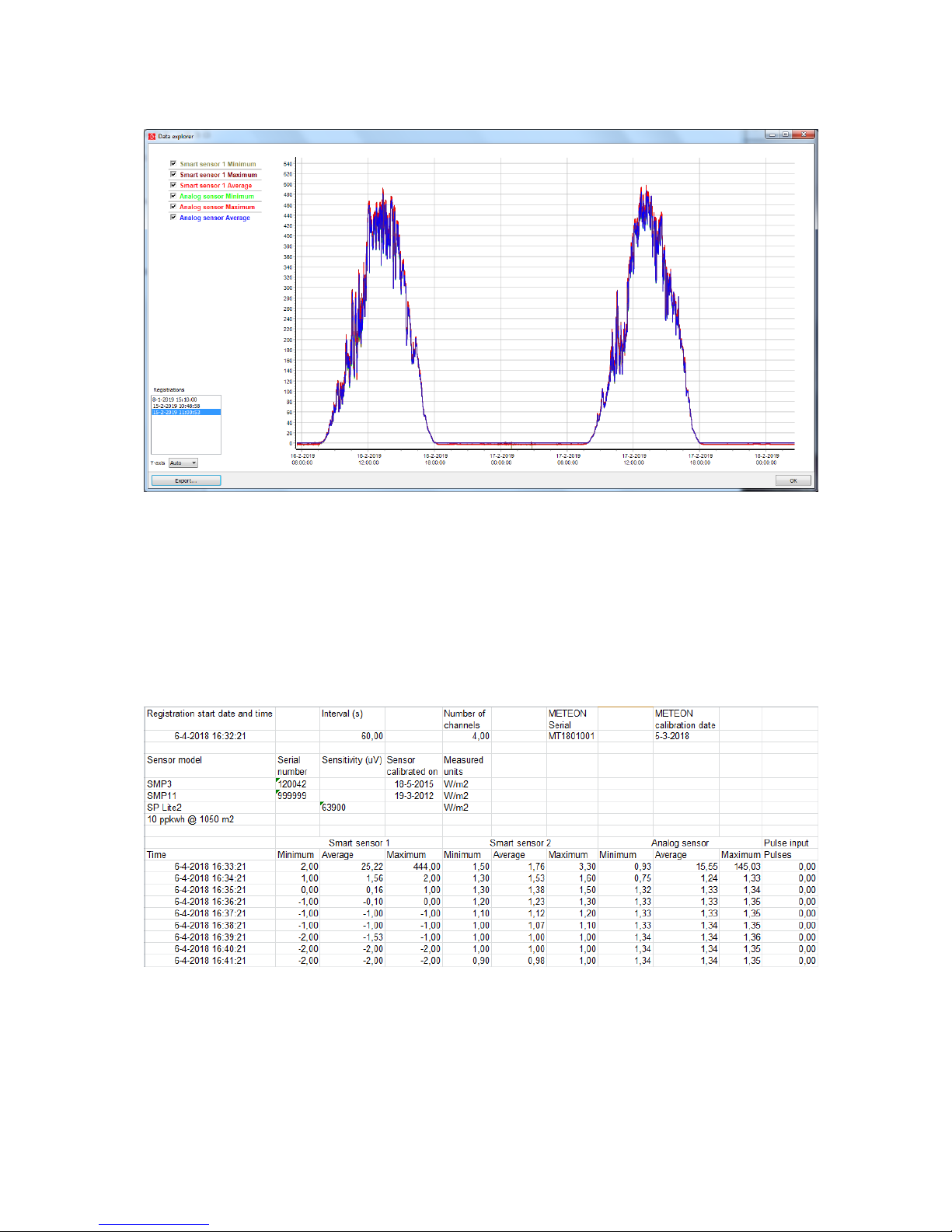
16.2 Data Explorer screen
When downloading the data from the METEON it is visualized with the above Data Explorer screen.
This graph with auto scaling shows the selected sensors as selected in the top left corner. When
sensors are not required they can be deleted with by deleting the checkmarks in the top left section.
In the registration menu (bottom left corner) one of the downloaded registrations can be selected.
16.3 Export
With export the selected registration can be transferred to the PC in XLS or CSV format.
Example of xls import format
Page 21
21
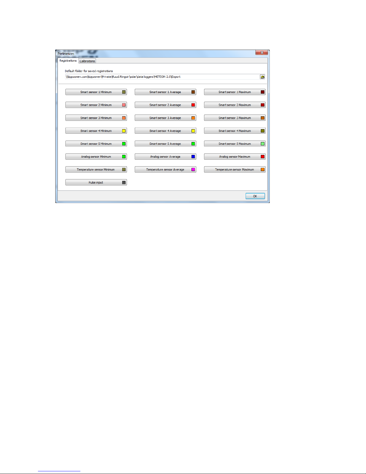
16.4 Preferences screen
Here the default folder for downloaded data can be set, as well as the colors used per sensor.
The Calibrations tab to define a location to store calibrations is not used at this moment.
Page 22
22
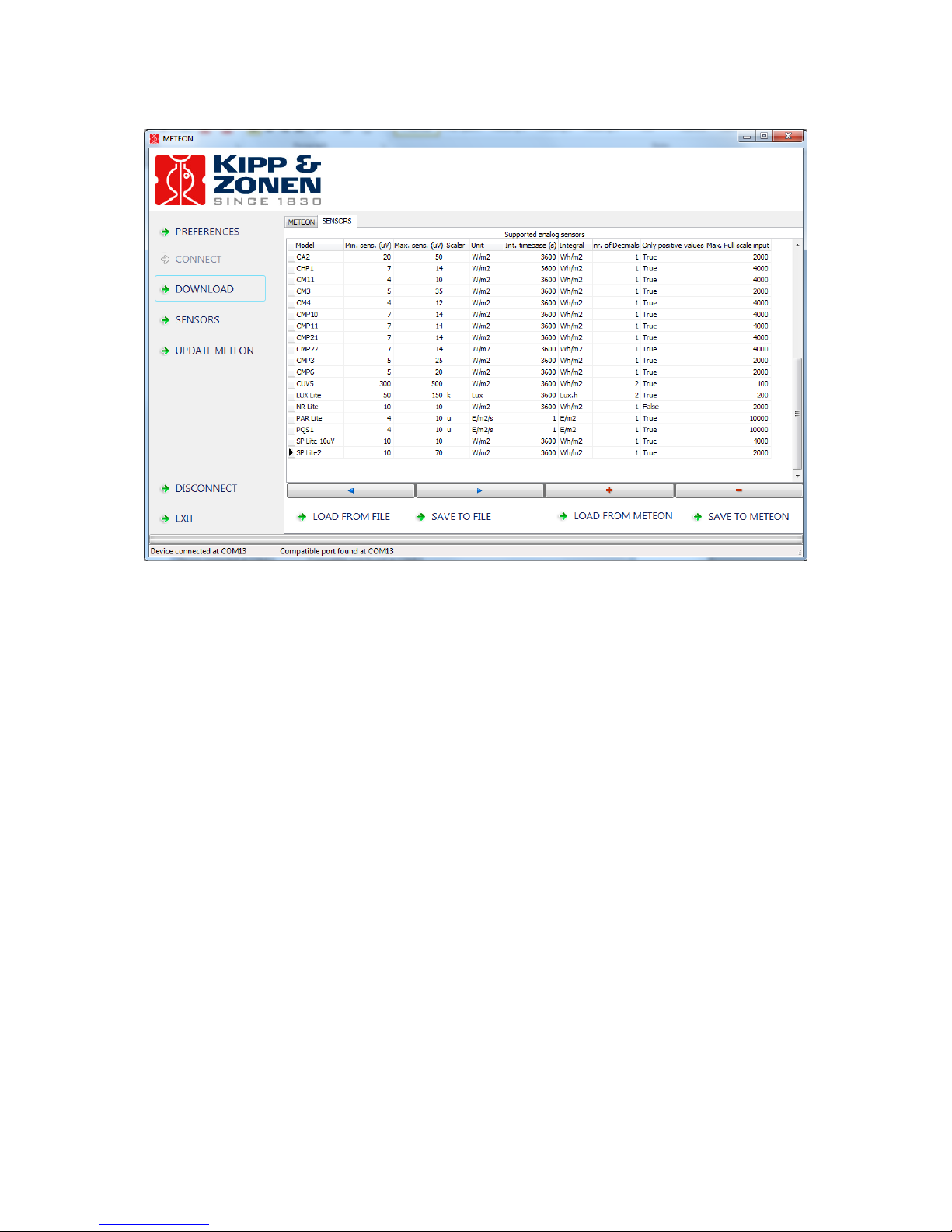
16.5 Sensor list
The above list comes as standard with the METEON but can be edited by the user.
When a new (analog) sensor needs to be added this can be done by pressing the + field and entering
the relevant data for this sensor. By clicking in one of the cells, the present data can be altered. With
[SAVE TO METEON] the new sensor list can be transferred to the METEON memory. After this upload it
will be available in the METEON menu under the available analog sensors.
The options [LOAD FROM FILE] and [SAVE TO FILE] give you the option to save (and load ) the sensor
list to PC as well. The format is XML.
16.6 Update METEON
If available this screen asks for the location of a "bin" file that contains the new METEON Firmware.
Once loaded it requires a reset and will shows the new functionality afterwards.
 Loading...