

Page 1
Instruction Manual
LAS MkII ET System
Page 2

Page 3

Important User Information
.
Dear customer, thank you for purchasing a Kipp & Zonen instrument. It is essential that you read this manual completely for a
full understanding of the proper and safe installation, use, maintenance and operation of your new LAS MkII ET System.
Please read this manual in conjunction with the instruction manual for the LAS MkII scintillometer.
We understand that no instruction manual is perfect, so should you have any comments regarding this manual we will be
pleased to receive them at:
Kipp & Zonen B.V.
Delftechpark 36, 2628 XH Delft, - or
P.O. Box 507, 2600 AM Delft,
The Netherlands
T: +31 (0) 15 2755 210
F: +31 (0) 15 2620 351
support@kippzonen.com
www.kippzonen.com
Warranty and liability
Kipp & Zonen guarantees that the product delivered has been thoroughly tested to ensure that it meets its published specifications.
The warranty included in the conditions of delivery is valid only if the product has been installed and used according to the
instructions supplied by Kipp & Zonen.
Kipp & Zonen shall in no event be liable for incidental or consequential damages, including without limitation, lost profits, loss
of income, loss of business opportunities, loss of use and other related exposures, however incurred, rising from the faulty and
incorrect use of the product.
Modifications made by the user may affect the instrument performance, void the warranty, or affect the validity of the CE
declaration or other approvals and compliances to applicable International Standards.
Copyright © 2012 Kipp & Zonen B.V.
All rights are reserved. No part of this publication may be reproduced, stored in a retrieval system or transmitted, in any form
or by any means, without authorisation by Kipp & Zonen.
Kipp & Zonen reserves the right to make changes to this manual, brochures, specifications and other product documentation
without prior notice.
Manual document number: V1208
st
Publication date: 1
August 2012
Instruction Manual - LAS MkII ET System
3
Page 4

Instruction Manual - LAS MkII ET System
4
Page 5

Table of Contents
.
Important User Information
.
3.........................................................................................................................................................................................
.
3
Table of Contents
1. Introduction
1.1 Product overview
1.2 Key parts of the LAS MkII ET system
2. Installation
2.1 Included with the system
2.1.1 LAS MkII scintillometer
2.1.2 Meteorological sensors and mast
2.1.3 NR Lite2 Net Radiometer
2.1.4 COMBILOG Data Logger
2.1.5 Additional items
2.2 Site selection procedure
2.2.1 LAS MkII scintillometer
2.2.2 The meteorological sensors and mast
2.3 Power supply
......................................................................................................................................................................................................................
..............................................................................................................................................................................................................................
......................................................................................................................................................................................................................
..........................................................................................................................................................................
.................................................................................................................................................................................................................................
....................................................................................................................................................................................................
...........................................................................................................................................................................................................
.......................................................................................................................................................................................
.........................................................................................................................................................................................................
...........................................................................................................................................................................................................
..........................................................................................................................................................................................................................
......................................................................................................................................................................................................
..........................................................................................................................................................................................................
.............................................................................................................................................................................
.................................................................................................................................................................................................................................
2.4 Assembling the meteorological mast and sensors
2.4.1 The mast
2.4.2 The mounting arms and sensors
2.5 Installing the mast
2.6 Mounting the data logger enclosure
2.7 The soil heat flux sensors
2.8 Sensor overview
2.9 Connecting the sensors
2.10 Installing the scintillometer
..........................................................................................................................................................................................................................................
.........................................................................................................................................................................................
....................................................................................................................................................................................................................
...........................................................................................................................................................................
....................................................................................................................................................................................................
.........................................................................................................................................................................................................................
.........................................................................................................................................................................................................
..........................................................................................................................................................................................
...........................................................................................................................................
5
7
7
8
9
9
9
10
11
11
11
12
12
12
13
14
14
15
16
17
19
19
20
23
3. Accessories
.................................................................................................................................................................................................................................
4. Software installation and configuration
4.1 EVATION software
4.2 LAS MkII configuration
4.3 Effective height calculator
4.4 COMBILOG support software
4.4.1 Setting communication parameters
4.4.2 Communicating with the COMBILOG
4.4.3 Original COMBILOG module settings and programs
5. Operation and measurement
5.1 Real-time monitoring of measurements
5.1.1 Via COMBILOG support software
5.1.2 Via the COMBILOG display
5.2 Calibration coefficients
5.3 Data files
...........................................................................................................................................................................................................................................
.....................................................................................................................................................................................................................
.........................................................................................................................................................................................................
..................................................................................................................................................................................................
...........................................................................................................................................................................................
.................................................................................................................................................................................
...............................................................................................................................................................................
.................................................................................................................................................................................
...................................................................................................................................................................
........................................................................................................................................................................................
.....................................................................................................................................................................................................
.........................................................................................................................................................................................................
.................................................................................................................................................
...............................................................................................................................................
25
27
27
27
27
27
28
29
29
31
31
31
32
32
32
Instruction Manual - LAS MkII ET System
5
Page 6

.
6. Maintenance and recalibration
6.1 Check the power is on
6.2 Check COMBILOG date and time
6.3 Check sensor signals
6.4 Check sensor condition
6.5 Check cables and connections
.
..........................................................................................................................................................................
............................................................................................................................................................................................................
....................................................................................................................................................................................
...............................................................................................................................................................................................................
.........................................................................................................................................................................................................
.........................................................................................................................................................................................
6.6 Check condition of the mast, guy wires and anchoring
6.7 Download the data from the COMBILOG
6.8 Check the LAS MkII Scintillometer
..................................................................................................................................................................
..............................................................................................................................................................................
...............................................................................................................................
.
33
33
33
33
33
33
33
34
34
7. Specifications
8. Trouble shooting
9. Customer support
Appendix A. System installation form
Using this table
Click on any item in the table of contents to be taken directly to the relevant page.
Click on the Kipp & Zonen logo at the bottom of any page to be taken back to the table of contents.
...........................................................................................................................................................................................................................
.................................................................................................................................................................................................................
...............................................................................................................................................................................................................
..............................................................................................................................................................
35
37
39
41
Instruction Manual - LAS MkII ET System
6
Page 7

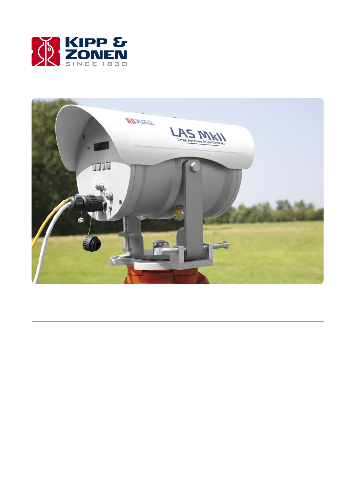
1. Introduction
.
Throughout this manual the following symbols are used to indicate to the user important information.
General warning about conditions, other than those caused by high voltage electricity, which may result in physical
injury and/or damage to the equipment or cause the equipment to not operate correctly.
Note Useful information for the user
1.1 Product overview
Note Please read this manual in conjunction with the instruction manual for the LAS MkII scintillometer.
The LAS MkII ET System (ET stands for evapo-transpiration) is designed for scintillometer-based surface flux measurements and is
specially intended for Earth energy balance and water management studies. Evapo-transpiration is an important term of the
surface energy budget:
Q*
= H + L
E + G
V
s
[W/m²]
Q* is the available energy, also known as the net radiation (Rn), H the sensible heat flux, L
where
E the latent heat flux and Gs
v
the soil heat flux. In some cases extra storage and/or advective terms can be added to the surface energy balance. The evapo-
transpiration (
latent heat flux (L
where L
This means that
a) An energy flux (L
b) As a mass flux (
The latent heat flux (L
ET), which stands for the evaporation (E ) from bare soil and the transpiration (T ) by vegetation, is related to the
E) as follows:
v
is the latent heat of vaporisation (the energy required to evaporate 1 kg of water, Lv ~2.45 × 10⁶ J kg-1).
v
ET
LvE
=
L
v
ET can be expressed as:
E) in W/m², mostly used in meteorology, or
v
ET) in mm/day, mostly used in hydrology, where 1 W/m² is equal to 0.0353 mm of water per day.
E), or ET , is an important term in the soil-water balance:
v
∆S = input - output
where ∆S is the change of storage of water in the soil, which is the result of the amount of input into the soil (due to rainfall or
irrigation) minus the amount of loss of water (due to evapo-transpiration, surface run-off and drainage).
The LAS MkII ET System has been developed to provide area-representative surface fluxes of sensible heat (
E). A unique feature is the line of sight path-integrating capability of the large aperture scintillometer. This allows the user
(L
v
H) and latent heat
to measure area-averaged surface fluxes of sensible heat at scales from 100 m to 4.5 km, over both homogenous and moderately
heterogeneous areas.
Traditional measurement techniques (the eddy-covariance method, flux-profile method, Bowen ratio method and lysimeters) are
point (in-situ) measurements and therefore are less representative of large areas, particularly the pixel area of satellite instruments.
Instruction Manual - LAS MkII ET System
7
Page 8
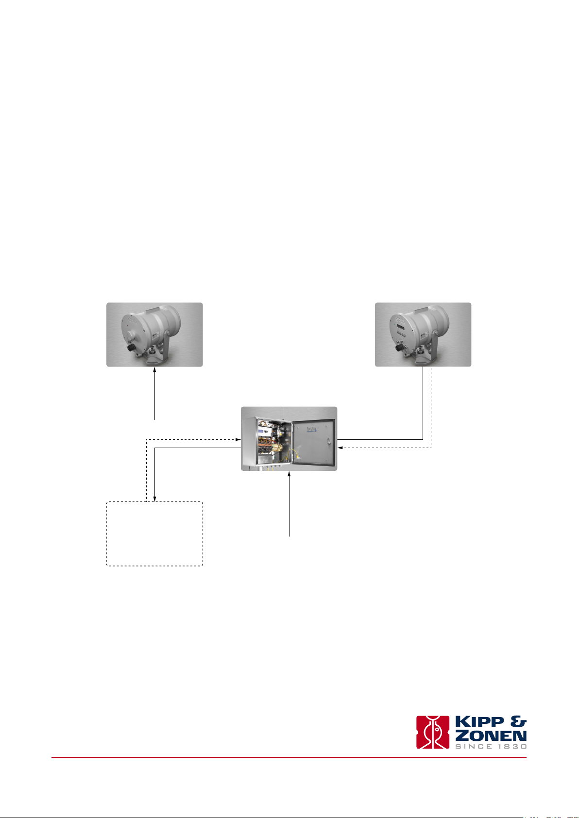
1.2 Key parts of the LAS MkII ET system
The LAS MkII ET system consists of four parts; a LAS MkII scintillometer, an extended set of meteorological sensors with a mast, a
data logger in a weatherproof enclosure, and data processing software to run on a Windows® compatible computer.
2
The structure parameter of the refractive index of air (C
are used to determine the surface flux of sensible heat (H). By adding a second temperature sensor, net radiometer, and soil heat flux
sensors, the latent heat flux (L
E) can be derived, via
v
E is the residual term of the energy balance.
L
v
The data processing of the LAS MkII ET system is done by the EVATION (evapotranspiration) software program. This user-friendly
program, developed by Kipp & Zonen, processes the raw data to fluxes of sensible and latent heat.
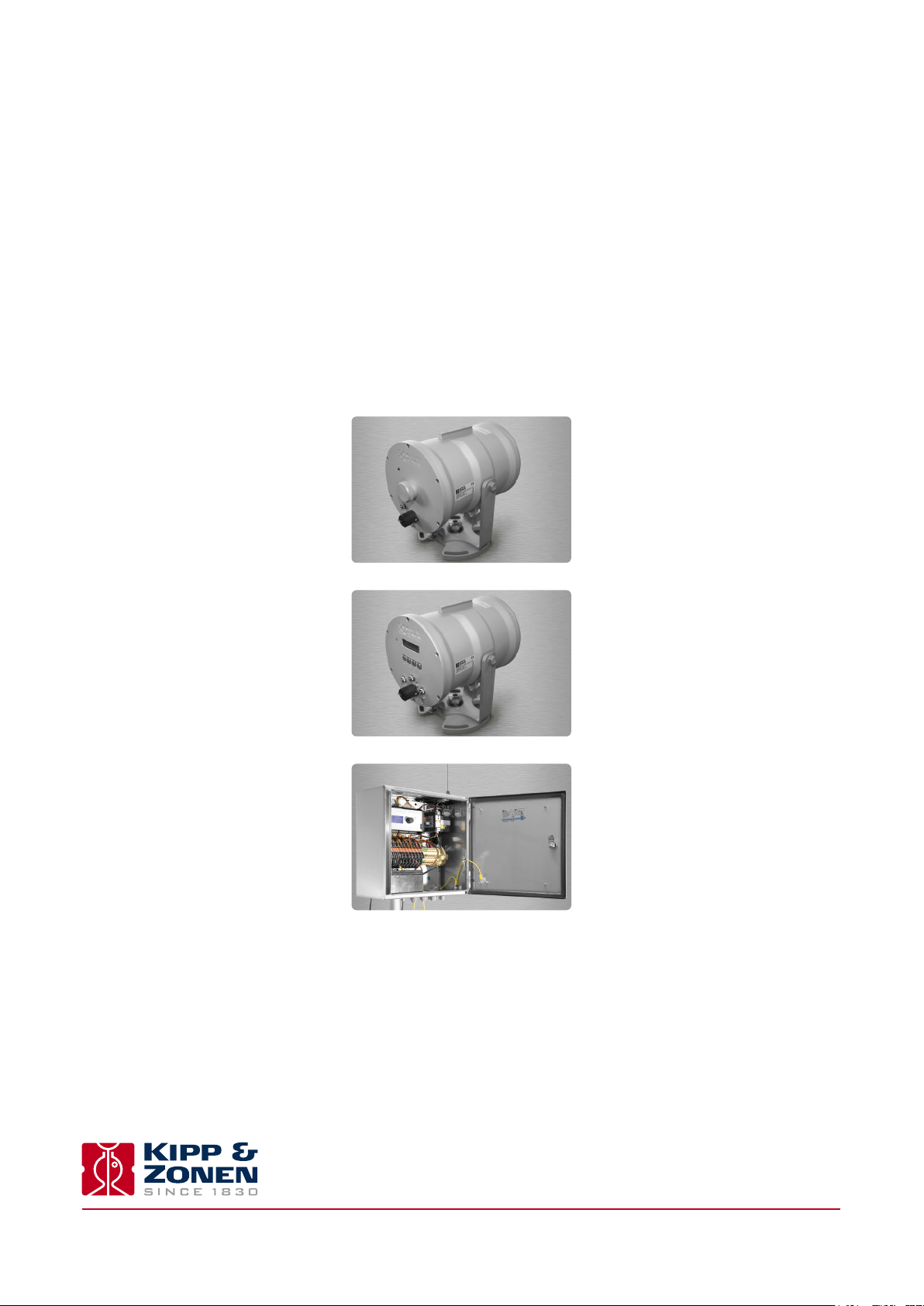
LAS MkII transmitter
) measured by the LAS MkII, air temperature, wind speed, and air pressure,
n
LVE
= Q*
-
H - G
s
LAS MkII receiver
Datalogger
Instruction Manual - LAS MkII ET System
8
Page 9
2. Installation
.
Please follow the instructions in this section carefully for the mechanical and electrical installation of the LAS MkII ET System.
Do not turn on power to the transmitter or receiver until instructed to do so.
Ensure that fixings and mountings are securely tightened when instructed to do so.
2.1 Included with the system
Check the contents of the shipment for completeness (see below) and note whether any damage has occurred during transport. If
there is damage, a claim should be filed with the carrier immediately. In the case of damage and/or the contents are incomplete,
contact your local Kipp & Zonen representative or e-mail the Kipp & Zonen customer and product support department at:
support@kippzonen.com
Note The LAS MkII is rugged, but it contains sensitive optical and electronic parts. Please keep the original packaging
to safely transport the scintillometer to measurement sites or for other shipments.
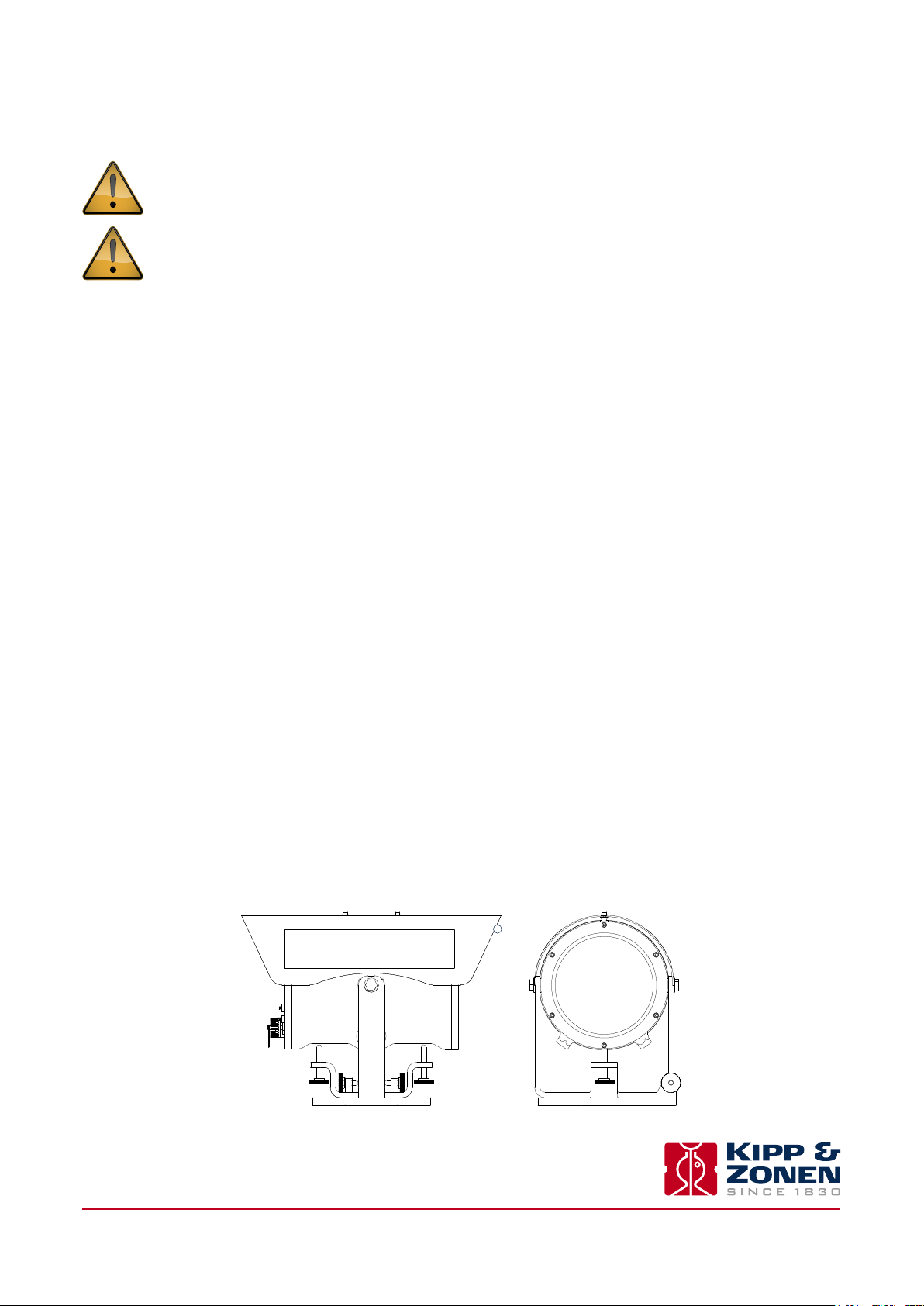
2.1.1 LAS MkII scintillometer
The following items are included with the LAS MkII scintillometer:
LAS MkII transmitter with pan and tilt adjuster and baseplate
LAS MkII receiver with pan and tilt adjuster and baseplate
2 × alignment telescope with detachable mounting, adjusted for each transmitter and receiver
2 × sun shield with two fixing screws
2 × 100 mm diameter aperture restrictor with fixing kit, for transmitter and receiver
2 × 10 m cable with 4-pin plug for transmitter signal output and receiver analogue connections
1 x 10 m cable with 8-pin plug for receiver digital communication connections
2 x 10 m cable with 4-pin connector for 12 VDC power input
2 x 3 mm hexagonal Allen keys, for fitting the sun shields
2 x 4 mm hexagonal Allen keys, for fitting the telescopes
1 x CD-ROM containing EVATION software and a pdf file of the LAS MkII instruction manual
8 x spare desiccant packs
For a full description of the LAS MkII scintillometer refer to its instruction manual.
1
Instruction Manual - LAS MkII ET System
9
Page 10

.
2.1.2 Meteorological sensors and mast
The following items are included with the meteorological sensors and mast:
Temperature sensor x 2, upper and lower
Range -40°C to +60 °C
Output PT-100
Calibration 0.03°C 1/10 DIN accuracy
(4-wire)
Wind speed sensor
Operating temperature -25°C to +80 °C
Range 0 to 60 m/s
Voltage and power sensor Nominal 12 VDC
Voltage and power heater Nominal 12 VDC (max 7 Watt)
Output Digital 0 to 600 Hz
(~2 mA)
Wind direction sensor
Operating temperature -25°C to +80 °C
Range 0 to 360°
Voltage and power sensor Nominal 12 VDC
Voltage and power heater Nominal 12 VDC (max 7 Watt)
Output 8-bit Gray Code
(~2 mA)
Air pressure sensor (mounted inside data logger enclosure)
Operating temperature -25°C to +70°C
Range 600 to 1050 hPa
Voltage and power Nominal 12 VDC
Output 0.3 to 4.9 VDC
(~10 mA)
Soil heat flux sensor
Operating temperature -30°C to +70°C
Range ± 2000 W/m²
Output ± 20 mV
Mast, telescopic
Height 4 m maximum
Guy wires 3 stainless steel wires with securing pins
Baseplate With socket for mast
Lightning protection Mast top rod and earth spike
Mounting arms U-shaped - wind speed and direction sensors
2-sided - upper temperature sensor and NR Lite2
1-sided - lower temperature sensor
Instruction Manual - LAS MkII ET System
10
Page 11

.
2.1.3 NR Lite2 Net Radiometer
The mast includes a mounting arm for the Kipp & Zonen NR Lite2 net radiometer.
Net radiation sensor, NR Lite2
Operating temperature -40°C to +80 °C
Range ± 2000 W/m²
Output ~ ± 20 mV
2.1.4 COMBILOG Data Logger
The data logger is fitted in a stainless steel weather-proof enclosure with a clamp for the mast.
COMBILOG 1022 data logger
Stainless steel enclosure, over-voltage input protection, mast mountings
Operating temperature -20°C to +60 °C
Supply voltage 10 to 30 VDC
Analogue inputs 8
Digital I/O 6
Interfaces RS-232/RS-485/USB/Ethernet
Data storage 7 MB internal RAM, expandable by SD card
Optional AC to 12 VDC power supply and backup battery
Optional GSM data modem
(16-bit)
2.1.5 Additional items
The data logger is fitted in a stainless steel weather-proof enclosure with a clamp for the mast.
• LAS MkII manual, EVATION software and manual (supplied on CD-ROM with the LAS MkII scintillometer)
• Documentation for the meteorological sensors
• COMBILOG support software (supplied on CD-ROM) and manual
• NR Lite2 instruction sheet and calibration certificate (supplied with the NR Lite2)
Note Kipp & Zonen reserves the right to make changes to specifications without prior notice.
Note The ET system is not supplied with a relative humidity sensor. A default value (50%) is used in the EVATION
software. Uncertainties in RH have little effect on the sensible heat flux and the evapo-transpiration.
Instruction Manual - LAS MkII ET System
11
Page 12
2.2 Site selection procedure
This section provides information on selecting an appropriate installation site.
2.2.1 LAS MkII scintillometer
For the general installation and site requirements of the LAS MkII scintillometer please refer to its manual.
2
For reliable air (C
These are:
• The LAS MkII transmitter and receiver must be placed on robust and vibration free supports.
• Avoid saturation of the signal by installing the LAS MkII at a suitable height (depending upon surface conditions and path length).
• Ensure that the LAS MkII is measuring in the Constant Flux Layer for reliable flux derivations of the C
• (depends on surface characteristics).
Pay attention to orientation, installation height and beam height requirements. For detailed information refer to
the LAS MkII instruction manual.
2.2.2 The meteorological sensors and mast
The LAS MkII receiver is supplied with a 10 m long cable for connecting the two 0 to 2 V analogue signal outputs to the data
logger. Normally, the weather station is sited within 10 m of the receiver, but, if necessary, these cables can be extended to
optimise the weather station location.
) and flux (H and LvE) measurements it is important to meet the installation requirements of the scintillometer.
n
2
signal using MOST
n
Selecting an appropriate site for the weather station is critical in order to obtain data that is representative of the LAS beam
path. It must be sited away from the influence of obstructions such as buildings, trees and other objects which might disturb the
measurements of wind speed, temperature and net radiation. As a rule of thumb, the minimum distance from an obstruction of
height h is 10h.
The ground around the mast should be flat. As the anchoring of the mast is based on 3 securing pins to hold the
guy wires, the soil must be stable enough to hold the load in high winds or when the ground is wet. If in doubt,
use a concrete foundation.
There must be a good, firm place to drive in the lightning rod earth spike.
Instruction Manual - LAS MkII ET System
12
Page 13
2.3 Power supply
The LAS MkII transmitter requires 12 VDC nominal (9.6 to 18 VDC), 6 W maximum with heater off and 54 W maximum with heater
on (typically 26 W).
The LAS MkII receiver requires 12 VDC nominal (9.6 to 18 VDC), 5 W maximum with heater off and 51 W maximum with heater
on (typically 23 W).
For more information, please read the LAS MkII scintillometer manual.
The meteorological sensors and data logger require 12 VDC nominal, a total of 4 W maximum with heaters off and 18 W maximum
with heaters on.
Note The data logger power requirement will be higher if an optional communication modem is fitted. Please refer to
the data logger and/or modem manual.
Mains AC power must be available for AC to 12 VDC convertors, if solar panel / battery power supplies are not used.
LAS MkII - Transmitter LAS MkII - Receiver
12 VDC / ~0.5 A
12 VDC / ~3 A
(+ window heater)
Temperature sensor x2
Wind speed sensor
Wind direction sensor
Soil heat flux sensors x2
Net radiometer
Sensor signals
12 VDC
in stainless steel enclosure
Data logger
with air pressure sensor
12 VDC / ~0.7 A
12 VDC / ~4.5 A max
(+ all heaters)
12 VDC / ~0.4 A
12 VDC / ~3 A
(+ window heater)
2
U
and U
C
n
DEMOD
signals
Instruction Manual - LAS MkII ET System
13
Page 14
2.4 Assembling the meteorological mast and sensors
2.4.1 The mast
Assemble the mast horizontally on the ground in accordance with the dimensions shown below.
Ø 50 mm~ 4.0 m
20 °
~ 3.0 m
~ 1.7 m
~ 2.0 m
The safe clamping zone of each section is indicated by red stripes on each mast section, as shown below.
Ø 55 mm
Ø 60 mm
1. The nominal mast height of 4 m is achieved when clamping the sections at their lower marks.
2. The guy wires are supplied pre-assembled to triangular collar. This must be slid over the upper section of the mast, as shown
above, before fitting any other items.
3. The base plate has a socket for the bottom of the lowest mast section.
Instruction Manual - LAS MkII ET System
14
Page 15

.
2.4.2 The mounting arms and sensors
Assemble the mounting arms and sensors to the mast as in the image below.
1. The U-shaped mounting arm is fitted to the top of the mast.
The wind direction sensor (WD) is mounted on the lower (shorter) ‘leg’ of the arm.
The wind speed sensor (u) and lightning rod are mounted on the upper (longer) ‘leg’.
2. The 2-sided mounting arm is fitted to the middle section of the mast at about 2.7 m.
The upper temperature sensor (T+) is mounted on the longer side of the arm.
The NR Lite2 net radiometer (Q* or R
The bubble level and the anti-bird stick must be facing upwards.
The net radiometer must be pointing towards the equator to avoid shadows from the mast.
) is mounted on the shorter side of the arm.
n
3. The 1-sided mounting arm is fitted to the lower section of the mast at a height of about 0.5 m.
The lower temperature sensor (T- ) is mounted on the arm.
The sensor must be oriented vertically below the upper temperature sensor.
When the temperature sensors are positioned too close to each other no reliable direction for the temperature
gradient can be measured, particularly during the day. The minimum distance between the sensors is 1.7 m.
The lower temperature sensor should not be mounted more than 1m above the ground (or the effective surface
height, such as the mean level of grass or a crop around the mast).
4. Use cable ties to fix the sensor cables to the mast and mounting arms and lead the cables to the lower end of the mast, where
at a later stage the data logger enclosure will be mounted.
Instruction Manual - LAS MkII ET System
15
Page 16

2.5 Installing the mast
Two persons are required to erect the mast. One person holds the mast in an upright position whilst the second person determines
the positions where the guy wire securing pins will be driven into the ground.
1. The lower guy ends are 0.3 m longer than theoretically required in order to hold the mast vertical on an uneven surface. Two
guy wire ends have a plain thimble, while the third has a bottle screw for adjustment after erection of the mast.
The 3 guy rope securing pins should be driven in at an angle about 20 ° outwards from vertical, as shown below
and in 2.4.1.
2. The securing pin for the guy wire with the bottle screw should be driven in last. First set the bottle screw to its maximum
length. Locate the securing pin so that the mast leans slightly away from it. Use the bottle screw and a spirit level to make
the mast vertical.
The 3 guy ropes should have moderate and equal tension, do not put a bending force on the mast.
Instruction Manual - LAS MkII ET System
16
Page 17

.
3. Fix down the base plate of the mast with 4 smaller securing pins.
4. Finally, drive in the lightning rod earth spike
Check the guy wire tension and the mast alignment frequently. If the ground is not firm enough to keep the mast
vertical in all weather conditions, use concrete for anchoring.
2.6 Mounting the data logger enclosure
Once the mast, with mounting arms and sensors, is erected and levelled the stainless steel data logger enclosure can be fixed to
the lower section of the mast, as shown in the next two drawings. Use the two clamps already fitted to the back of the enclosure.
Allow at least 0.1 m clearance below the enclosure for the cables to enter.
Securing pin
Guy wires
120 °
Mast
Temperature sensors
Data logger enclosure
Base plate
Net radiation sensor
(towards equator)
Securing pins
Instruction Manual - LAS MkII ET System
17
Page 18

.
Lightning rod
Wind speed
Wind direction
Min. 1.7 m
Max. 1.0 m
Upper temperature
0.45 m
Lower temperature
Data logger enclosure
Guy wire collar
Net radiation
1.2 m
Lightning rod
earth spike
The installation should now be as in the drawings above.
Note Check that the net radiometer is horizontal using the bubble level on its upper surface.
Instruction Manual - LAS MkII ET System
18
Page 19

2.7 The soil heat flux sensors
The last sensors to be installed are the soil heat flux plates. Place them on the same side of the mast as the net radiation sensor
(towards the equator) and at a spot that is not disturbed by footsteps. The measurements should be representative of the
general area covered.
Do not position the plates directly beneath the net radiation sensor, as they may disturb the measurements.
Depending on the soil type and the presence of vegetation the plates should be buried at a depth of about 30 mm for bare soil
conditions or just beneath the surface of fully covered soil (a few mm). In the latter case the amount of ‘missing’ flux is as small
as possible. Both plates should be at the same depth and laterally separated by 30 to 100 mm.
Do not bury the plates too deeply. At depths of 100 mm they can underestimate the soil heat flux by more than 50%. Ensure that
the plates are not measuring in air gaps or cracks. They must be in full contact with the soil and at the same depth.
2.8 Sensor overview
Sensor Height/depth Arm Orientation/Direction
Wind speed (u) 4.4 m U-shaped Long ‘leg’
Wind direction (WD) 4.2 m U-shaped Short ‘leg’
+
Upper air temperature (T
Net radiation (Q* or R
Lower air temperature (T
Soil heat flux plate 1 (G
Soil heat flux plate 2 (G
Air pressure (P) - In logger enclosure Breathes through sintered vent in bottom
of data logger enclosure
Data logger enclosure At least 0.1 m On mast
) 2.7 m 2-sided Opposite to radiation sensor
) 2.7 m 2-sided Towards equator to avoid shadows
n
-
) 0.5 to 1.0 m 1-sided Directly below upper temperature sensor
or HFP1) 3 to 30 mm In ground Towards equator, not below net radiometer
1
or HFP2) 3 to 30 mm In ground As flux plate 1, separated by 30-100 mm
2
Instruction Manual - LAS MkII ET System
19
Page 20

2.9 Connecting the sensors
Note The air pressure sensor (P) is pre-installed inside the data logger enclosure.
Pressure
sensor
LAS MkII receiver + sensors
Data
PC
Data logger
Over voltage
Signals
12 VDC power
protection
Measurement
signals
12 VDC power
Power terminal
with internal fuse
Steel enclosure
12 VDC power
All cables (signal and power) enter the data logger enclosure at the bottom through weatherproof cable glands and connect to
the over-voltage protection (OVP) module terminals as in the following table.
Digital input channels
Instrument Function/Wire OVP Input
Yellow 1 I/O 1
Wind speed
Green 2 0 V
Yellow 3 I/O 2
Wind direction
Green 4 0 V
Instruction Manual - LAS MkII ET System
20
Page 21

Analogue input channels
Instrument Function/Wire OVP Terminal input
13 SRC
Yellow 14 In+
Pressure sensor AIN1
Green 15 In-
16 AGND
17 SRC
Red 18 In+
NR Lite2 AIN2
Blue 19 In-
20 AGND
21 SRC
Red 22 In+
LAS MkII
Yellow
24 AGND
25 SRC
Green 26 In+
LAS MkII
Yellow
28 AGND
(U
2) AIN3
C
n
(U
) AIN4
demod
(jumper to terminal 27) 23 In-
(jumper to terminal 27) 27 In-
White 29 SRC
Brown 30 In+
(upper sensor) AIN5
Pt-100
Green 31 In-
Yellow 32 AGND
White 33 SRC
Brown 34 In+
(upper sensor) AIN6
Pt-100
Green 35 In-
Yellow 36 AGND
37 SRC
White 38 In+
(heatflux plate) AIN7
HFP1
Green 39 In-
40 AGND
41 SRC
White 42 In+
(heatflux plate) AIN8
HFP2
Green 43 In-
44 AGND
Instruction Manual - LAS MkII ET System
21
Page 22

Power terminals (low voltage DC only)
Instrument Function/Wire OVP Terminal connection side Power
PE Ground
PE Ground
PE Ground
PE Ground
Pink + Brown 45 0 V
Wind speed
Grey + White 46 +12 V
Pink + Brown 47 0 V
Wind direction
Grey + White 48 +12 V
Blue 49 0 V
Pressure sensor
(pre-mounted)
Red 50 +12 V
O V from external
51 0 V
power supply
12 V from external
52 +12 V
power supply
Power terminals (mains AC power)
Mains power Function/Wire OVP Terminal connection side Power
Ground PE Ground
Live 100 to 240 VAC L1 (250 V fuse) Live
Neutral N Neutral
PE Ground
Check that everything is properly fixed to the mast and that the net radiation sensor is level.
Read the relevant sections of the COMBILOG data logger manual.
Note The COMBILOG data logger in the ET System is pre-configured by Kipp & Zonen and will automatically start
measuring once connected to a power supply.
Switch on the power to the data logger enclosure and verify that all the sensors are working properly. Adjust the date and time
setting of the COMBILOG data logger if necessary.
At this stage do not turn on the power to the LAS MkII scintillometer.
Instruction Manual - LAS MkII ET System
22
Page 23

.
When the system is working properly, roll up extra lengths of signal and power cables and fix them to the mast behind the data
logger enclosure using cable ties.
Do not lay cables on the ground as insects and animals might damage them.
2.10 Installing the scintillometer
Install, configure and optically align the LAS MkII scintillometer using the display and menu keys, or the EVATION software, as
described in the LAS MkII Manual.
When the scintillometer is working properly, switch off the power. Ensure that the power to the data logger enclosure
is turned off.
2
Connect the receiver analogue outputs for Log U
and U
C
n
Switch on the power to the scintillometer transmitter and receiver and to the data logger enclosure and verify that the
scintillometer signals are displayed and recorded correctly.
to the data logger OVP inputs, as in the previous table.
DEMOD
Note As the final step we recommend filling in the Installation Form for the System (see Appendix A). The information
in this form will be used to configure the EVATION software.
Instruction Manual - LAS MkII ET System
23
Page 24

Instruction Manual - LAS MkII ET System
24
Page 25

3. Accessories
.
There are a number of accessories available for the LAS MkII scintillometer and these are described in the LAS manual.
Instruction Manual - LAS MkII ET System
25
Page 26

Instruction Manual - LAS MkII ET System
26
Page 27

4. Software installation and configuration
.
The software required for the LAS MkII ET system consists of the following programs:
• EVATION software to process measured data into surface fluxes and to configure the LAS MkII scintillometer (as an alternative
to using the receiver display and menu keys).
• COMBILOG support software to (re)configure the data logger. This is supplied with the logger manual.
4.1 EVATION software
The installation, configuration and operation of the EVATION software are described in the LAS MkII Manual.
4.2 LAS MkII configuration
Configuration of the LAS MkII receiver using the display and menu keys, or the EVATION software, is described in the
LAS MkII Manual.
4.3 Effective height calculator
Use EVATION to calculate the effective height of the scintillometer path as described in the LAS MkII Manual.
4.4 COMBILOG support software
The COMBILOG support software enables the user to communicate with COMBILOG data loggers, via the RS-232, RS-485, Ethernet
or USB interfaces. In this way the user can re-configure the data logger, monitor measurements in real-time, change the logger date
and time, and download data from the internal memory.
The optional SD cards for memory expansion must be taken out and downloaded directly to a computer. Note that the
COMBILOG data logger in the ET System is pre-configured by Kipp & Zonen and will automatically start measuring once
connected to a power supply.
The installation of the COMBILOG support software is carried out as follows:
• Insert the installation CD into the computer drive
• In case the installation does not start automatically, click on ‘SETUP.exe’ on the COMBILOG CD-ROM
• Follow the on-screen instructions in the installation program
After successful installation a new program group called COMBILOG V×.×× (Icon: ) is created.
Instruction Manual - LAS MkII ET System
27
Page 28

.
4.4.1 Setting communication parameters
When the COMBILOG support software is started for the first time, the communication parameters must be configured in order
to communicate with the data logger. Select ‘Communication’ and the following window appears.
Set the communication parameters to suit the computer, for example:
Interface Kind: RS-232
Parameters:
ComPort COM1
Baudrate 19200
Char Format 8n1
Add Timeout 1000 ms
Click on ‘OK’.
The software is now ready to communicate with the COMBILOG data logger.
Instruction Manual - LAS MkII ET System
28
Page 29

.
4.4.2 Communicating with the COMBILOG
• Start the COMBILOG support software.
• Connect the PC to the COMBILOG data logger using the RS-232, RS-485, Ethernet or USB interfaces.
• Click on ‘File’ and select ‘Scan Bus’. The software will automatically scan for connected COMBILOG data loggers.
• The user can now select the data logger to communicate with.
4.4.3 Original COMBILOG module settings and programs
The data logger is pre-configured by Kipp & Zonen and will automatically start measuring when connected to a power supply. If
necessary the user can re-configure the data logger using the COMBILOG support software.
For further instructions the user is referred to the COMBILOG instruction manual and the COMBILOG support software. The
original configuration program for the data logger can be found on the supplied CD-ROM
Instruction Manual - LAS MkII ET System
29
Page 30

Instruction Manual - LAS MkII ET System
30
Page 31

5. Operation and measurement
.
Once the LAS MkII scintillometer and the weather station have been installed and connected to a power source, the data logger
of the LAS MkII ET System will automatically start recoding.
5.1 Real-time monitoring of measurements
The measurements can be monitored via the COMBILOG support software or by using the display on the data logger.
5.1.1 Via COMBILOG support software
Once a PC is connected to the COMBILOG data logger the measurements can be monitored in real-time via the ‘Measure’ window
(refer to the manual).
The measurements that can be viewed in real-time are shown in the following tables.
Sensors Symbol Unit Range
1 Air temperature upper (derived from 10) T+ °C -20 to +50
2 Air temperature lower
3 Relative humidity
4 Air pressure P hPa 600 to 1050
5 Wind speed U m/s 0 to 60
6 Wind direction WD o 0 to 360
7 Soil heat flux plate 1 G1 or HFP
8 Soil heat flux plate 2 G2 or HFP
9 Net radiation Rn-sn××× W/m² -250 to +1500
10 Resistance of upper Pt-100 PT100-sn××× Ω 80 to 120
11 Resistance of lower Pt-100 PT100-sn××× Ω 80 to 120
(derived from 11) T
(no sensor connected) RH % Default value 50
-
°C -20 to +50
-sn××× W/m² -200 to +200
1
-sn××× W/m² -200 to +200
2
Instruction Manual - LAS MkII ET System
31
Page 32

.
LAS signals Symbol Unit Range
1 Scaled C
2 Standard deviation of C
3 U
4 Standard deviation of U
5 Signal strength U
6 Standard deviation of U
2
PUCn21000 m
n
2
UCn2 V 0 to 2
C
n
2
Std PUCn21000 m
n
2
Std UCn2 V
C
n
Demod V 0 to 2
DEMOD
Std Demod V
DEMOD
5.1.2 Via the COMBILOG display
The output of each channel can also be monitored on the display of the COMBILOG using the knob on the data logger. Simply
by rotating and pressing the knob, the Main Menu can be scanned, which includes the actual measurements of each sensor plus
the units.
-2/3
0.01 to 1000
-2/3
5.2 Calibration coefficients
Some of the sensors of the LAS MkII ET system are supplied with calibration certificates, for example the net radiation sensor
and the soil heat flux plates. The calibration coefficients can be found in either the sensor instruction manuals / certificates or in
the original data logger program, which is stored in the COMBILOG’s internal memory. The original program with the calibration
coefficients is on the supplied CD-ROM.
5.3 Data files
The data files of the COMBILOG are formatted as follows (columns, separated by tabs):
1. Date
-
2. Time (= Begin
3. Air temperature upper sensor [T+, °C]
4. Air temperature lower sensor [T
5. Relative humidity [RH, %], the default value is 50 %
6. Air pressure [P, hPa]
7. Wind speed [u, m/s]
8. Wind direction [WD, °]
9. Soil heat flux (plate 1) [G1 or HFP1, W/m²]
10. Soil heat flux (plate 2) [G2 or HFP2, W/m²]
11. Net radiation [Q* or R
12. Scaled C
13. Standard deviation of scaled C
14. Demodulated signal strength [U
15. Standard deviation of Demod [V]
The number of columns (in this case 15) is constant and independent of the sensor configuration of the LAS MkII ET System. If
fewer sensors are used dummy values (-9999) are inserted in the ‘empty’ columns for the specific missing sensor.
Time of interval)
2
2
[PU
n
C
n
, m
-2/3
, W/m²]
n
]
2
n
-
, °C]
[m
DEMOD
-2/3
]
, V]
Note The columns must not be reordered.
A more detailed description of the data files and format can be found in the help file of the EVATION software.
Instruction Manual - LAS MkII ET System
32
Page 33

6. Maintenance and recalibration
.
Every time one visits the site, preferably at 2 week intervals, it is recommended to follow the inspection procedure described.
6.1 Check the power is on
Check if the green LED labelled ‘RUN’ on the COMBILOG data logger is activated. If so the display of the COMBILOG should show
the actual date and time and the real time measurements of all sensors. There is a fuse within the 12 VDC power distribution
terminal block in the data logger enclosure.
Press any menu key of the LAS MkII receiver to activate the display and check that it is measuring.
6.2 Check COMBILOG date and time
For instructions refer to the COMBILOG instruction manual.
6.3 Check sensor signals
When all the sensors of the weather station are operational the red LED ‘ERR’ of the COMBILOG is switched OFF. If one of the
sensors is malfunctioning the red LED is ON. The output of each channel can be seen on the display of the COMBILOG using the
‘SELECT’ rotate and press knob on the data logger.
The table in section 5.1.1 shows the range for each sensor of the LAS ET system. Check if the output of each sensor lies within
the given range and is reasonable for the prevailing conditions.
If one of the sensors is defective or malfunctioning the value -9999 is shown on the COMBILOG display. This applies for every
sensor except for the wind speed sensor. In case this sensor is malfunctioning a wind speed of 0 is displayed. Zero wind may
occur naturally, so the LED ‘ERR’ is inhibited. Therefore, check the wind speed on the display and verify this by looking at the
rotation of the sensor itself.
If one of the two scintillometer channels shows -9999, check the display of the LAS MkII receiver to verify the channel values
and LAS status.
6.4 Check sensor condition
Check the physical condition of all the sensors (net radiation, wind direction, wind speed, air temperature x 2). If necessary,
clean the sensors and remove any dirt, dust, sand, spider webs, insects, etc.
Check that the net radiation sensor is horizontal.
6.5 Check cables and connections
Check all cables and connections for damage, and ensure that all connections are tight, including those inside the data logger
enclosure.
6.6 Check condition of the mast, guy wires and anchoring
Check that the mast is vertical. The 3 guy ropes should have moderate and equal tension, do not put a bending
force on the mast.
Check the guy wire tension and the mast alignment frequently. If the ground is not firm enough to keep the mast
vertical in all weather conditions, use concrete for anchoring.
Instruction Manual - LAS MkII ET System
33
Page 34

6.7 Download the data from the COMBILOG
It is recommended to download data from the COMBILOG every two weeks.
• Connect a computer to one of the COMBILOG communication ports.
• Start the COMBILOG support software.
• Scan for available data loggers.
• Click on ‘Utilities’ and then ‘Read Logger’ and follow the instructions.
Refer to the COMBILOG manual for more information.
6.8 Check the LAS MkII Scintillometer
Carry out the maintenance checks for the LAS MkII as described in the scintillometer manual.
2
Check the receiver signal outputs (C
n
= C
2
n
the weather station. The values should be similar to the readings on the LAS receiver display.
Note The readings may not be exactly the same due to differences in sampling time, averaging and logging interval
configurations between the LAS receiver and the COMBILOG.
or PU
2
, and signal strength = Demod or U
C
n
) on the display of the COMBILOG at
DEMOD
Instruction Manual - LAS MkII ET System
34
Page 35

7. Specifications
The specifications of the LAS MkII scintillometer are given in the scintillometer manual.
The specifications of the COMBILOG data logger are given in the COMBILOG manual.
The specifications of the rest of the ET System are given in sections 2.1.2, 2.1.3 and the NR Lite2 Instruction Sheet.
Instruction Manual - LAS MkII ET System
35
Page 36

Instruction Manual - LAS MkII ET System
36
Page 37

8. Trouble shooting
The LAS MkII scintillometer and the ET System are designed for long periods of operation with little operator maintenance.
However, if a problem occurs that cannot be corrected using the standard operating information supplied in the preceding
sections of this manual, and in the scintillometer manual, use the information below to identify and solve the problem.
There are no user-serviceable parts within the LAS Mk II and the transmitter or receiver must not be opened
without the agreement and instruction of Kipp & Zonen.
In addition to the Trouble Shooting section of the LAS MkII manual, most problems are likely to be related to power or signal
connection issues.
• Power source problems at the weather station; short circuits, blown fuses, loose cables, etc.
• Sensor problems at the weather station; loose connections or damaged cables, dirt, levelling, sensor failure, etc.
If necessary, consult the separate manuals of the specific sensors and/or the COMBILOG manual for further information and
instructions to solve problems.
For software related problems, isolate which software program appears to give problems and consult the available help files for
further instructions.
If the problem persists contact support@kippzonen.com
Instruction Manual - LAS MkII ET System
37
Page 38

Instruction Manual - LAS MkII ET System
38
Page 39

9. Customer support
If you require any support for your Kipp & Zonen product please contact your local representative in the first instance. The
information can be found in the ‘Contact’ section of our website at http://www.kippzonen.com/?page/74152/Contact.aspx .
Alternatively, you can contact us directly at support@kippzonen.com .
Please include the following information:
• The ET system location
• The system Installation Form (see Appendix A)
• Instrument, sensor or data logger model with the problem
• Instrument, sensor or data logger serial number
• Details of the fault or problem
• Examples of data and log files
• Computer type and operating system
• Interfaces and power supplies used in the installation
• History of any previous repairs or modifications
• Pictures of the installation and site
• Overview of the local environment conditions
Kipp & Zonen guarantees that your information will not be shared with other organisations.
For details on the service options available please contact support@kippzonen.com .
Instruction Manual - LAS MkII ET System
39
Page 40

Instruction Manual - LAS MkII ET System
40
Page 41

Appendix A. System installation form
.
As the final step we recommend filling in an Installation Form for the System. The information in this form will be used to configure
the EVATION software.
General Information
……………………………………………………………………………………………………………………………………………………………………………………………………………………………………………... [Year/Month/Day]
Date:
Installed by:
Station name: ……………………………………………………………………………………………………………………………….. (convenient to use in EVATION as the working directory)
Weather station sensors / data logger channel
Sensor type Sensor serial number Logger input channel number Height/depth [m] Orientation [°]
……………………………………………………………………………………………………………………………………………………………………………………………………………………………………………………………….........
Coordinates of weather station:
…………………………………………………………………………………………………………………………………………………………………………………………………………………………………………………………………..... [Longitude, °]
…………………………………………………………………………...…………………………………………………………………………...………………………………………………………………………….. [Height, m] (above ground)
…………………………………………………………………………...…………………………………………………………………………...………………………………………………………………… [Elevation, m] (above sea level)
………………………………………………………………………………………………………………………………………………………………………........................ [Latitude, °]
Mean vegetation height at station site:
………………………………………………………………………………………………………………………………………………………………………........................... [m]
LAS MkII Scintillometer
Scintillometer serial number:
Exact path length (according to GPS or map): …………………………………………………………………………………………………………………………………………………………………………………… [m]
………………………………………………………………………………………………………………………………………………………………………………………………………………………………..
Transmitter
Coordinates of LAS MkII transmitter:
……………………………………………………………………………………………………………………………………………………………………………………………………………………………………………………………………. [Longitude, o]
…………………………………………………………………………………………………………………………………………………………………………………………............................................ [Height, m] (above ground)
…………………………………………………………………………………………………………………………………………………………………………………………………………………………... [Elevation, m] (above sea level)
Power adjustment setting:
……………………………………………………………………………………………………………………………………………………………………………………….......................................… [-]
Mean vegetation height at transmitter site:
………………………………………………………………………………………………………………………………………………………………………………… [Latitude, o]
……………………………………………………………………………………………………………………………………………………………………………………….. [m]
Instruction Manual - LAS MkII ET System
41
Page 42

Receiver
Coordinates of LAS MkII receiver:
……………………………………………………………………………………………………………………………………………………………………………………………………………………………………………………………………. [Longitude, o]
…………………………………………………………………………………………………………………………………………………………………………………………............................................ [Height, m] (above ground)
…………………………………………………………………………………………………………………………………………………………………………………………………………………………... [Elevation, m] (above sea level)
…........……………………………………………………………………………………………………………………………………………………………………………… [Latitude, o]
Signal strength on receiver display(UDEMOD):
Path length set at receiver:
……………………………………………………………………………………………………………………………………………………………………………………………………………………………. [m]
Mean vegetation height at receiver site:
………………………………………………………………………………………………………………………………………………………………….………… [mV]
……………………………………………………………………………………………………………………………………………………………………………………......…… [m]
Effective Height of LAS MkII Scintillometer
The accuracy of the fluxes of sensible heat and evapo-transpiration depends strongly upon the mean height of the LAS MkII
optical beam above the surface. In case the area is completely flat the average beam height can be easily derived from the
transmitter height and the receiver height.
In case the area is complex it becomes more difficult to determine the effective height of the beam. The EVATION software has
a special tool that helps the user to determine the effective height; the effective height calculator.
The calculator needs the following input data:
• The elevation of the transmitter site
• The installation height of the transmitter above the ground
• The elevation of the receiver site
• The installation height of the receiver above the ground
• The elevation and position of a number of points along the beam (a cross-section over the optical path)
By entering this information into the effective height calculator the software provides the effective height of the LAS MkII beam,
which will be used in the processing of data into fluxes.
Use a table, such as that below, to collect a number of cross-section points. In this case the ‘Reference’ point is ground level at
the transmitter site.
Points in optical
path cross-section
Elevation with respect to
reference site ground [± m]
Horizontal distance
from reference site [m]
Installation height of
LAS MkII with respect
to the site ground [m]
Transmitter site, Tx (Reference)
Intermediate point 1
Intermediate point 2
Intermediate point 3
Intermediate point 4
Intermediate point 5
Intermediate point 6
Intermediate point 7
Intermediate point 8
Intermediate point 9
Receiver site, RX
0
0
3
7.5
7.5
20
20
18
18
25
36
0
500
750
1000
2300
3000
3500
3700
4000
4500
4700 (Path Length)
50
30
Instruction Manual - LAS MkII ET System
42
Page 43

.
The effective height of the LAS beam can then be calculated as shown below.
Instruction Manual - LAS MkII ET System
43
Page 44

Our customer support remains at your disposal for any maintenance or repair, calibration,
supplies and spares.
Für Servicearbeiten und Kalibrierung, Verbrauchsmaterial und Ersatzteile steht Ihnen unsere
Customer Support Abteilung zur Verfügung.
Notre service 'Support Clientèle' reste à votre entière disposition pour tout problème de
maintenance, réparation ou d'étalonnage ainsi que pour les accessoires et pièces de rechange.
Nuestro servicio de atención al cliente esta a su disposición para cualquier actuación de
mantenimiento, reparación, calibración y suministro de repuestos.
HEAD OFFICE
Kipp & Zonen B.V.
Delftechpark 36, 2628 XH Delft
P.O. Box 507, 2600 AM Delft
The Netherlands
T: +31 (0) 15 2755 210
F: +31 (0) 15 2620 351
info@kippzonen.com
SALES OFFICES
Kipp & Zonen France S.A.R.L.
88 Avenue de l’Europe
77184 Emerainville
France
Kipp & Zonen Asia Pacific Pte. Ltd.
10 Ubi Crescent Lobby E
#02-93 Ubi Techpark
Singapore 408564
Kipp & Zonen USA Inc.
125 Wilbur Place
Bohemia
NY 11716
United States of America
Go to www.kippzonen.com for your local distributor or contact your local sales office
T: +33 (0) 1 64 02 50 28
F: +33 (0) 1 64 02 50 29
kipp.france@kippzonen.com
T: +65 (0) 6748 4700
F: +65 (0) 6748 6098
kipp.singapore@kippzonen.com
T: +1 (0) 631 589 2065
F: +1 (0) 631 589 2068
kipp.usa@kippzonen.com
Passion for Precision
 Loading...