

Page 1
Instruction Manual
LAS MkII • Scintillometer
Page 2

Page 3

Important User Information
.
Dear customer, thank you for purchasing a Kipp & Zonen instrument. It is essential that you read this manual completely for a
full understanding of the proper and safe installation, use, maintenance and operation of your new LAS MkII Scintillometer.
We understand that no instruction manual is perfect, so should you have any comments regarding this manual we will be
pleased to receive them at:
Kipp & Zonen B.V.
Delftechpark 36, 2628 XH Delft, - or
P.O. Box 507, 2600 AM Delft,
The Netherlands
T: +31 (0) 15 2755 210
F: +31 (0) 15 2620 351
support@kippzonen.com
www.kippzonen.com
Warranty and liability
Kipp & Zonen guarantees that the product delivered has been thoroughly tested to ensure that it meets its published specifications.
The warranty included in the conditions of delivery is valid only if the product has been installed and used according to the
instructions supplied by Kipp & Zonen.
Kipp & Zonen shall in no event be liable for incidental or consequential damages, including without limitation, lost profits, loss
of income, loss of business opportunities, loss of use and other related exposures, however incurred, rising from the faulty and
incorrect use of the product.
Modifications made by the user may affect the instrument performance, void the warranty, or affect the validity of the CE
declaration or other approvals and compliances to applicable International Standards.
Copyright © 2012 Kipp & Zonen B.V.
All rights are reserved. No part of this publication may be reproduced, stored in a retrieval system or transmitted, in any form
or by any means, without authorisation by Kipp & Zonen.
Kipp & Zonen reserves the right to make changes to this manual, brochures, specifications and other product documentation
without prior notice.
Manual document number: V1207
st
Publication date: 1
July 2012
Instruction Manual - LAS MkII Scintillometer
3
Page 4

Instruction Manual - LAS MkII Scintillometer
4
Page 5

Declaration of Conformity
.
We Kipp & Zonen B.V.
Delftechpark 36, 2628 XH Delft
P.O. Box 507, 2600 AM Delft
The Netherlands
Declare under our sole responsibility that the products:
Model LAS MkII
Type Large Aperture Scintillometer
to which this declaration relates are in conformity with European Harmonised Standards as published in:
Official Journal of the EC, Issue: C288 (30-09-2011)
The compliance of the product has been based on:
Emissions EN 61326-1:2006
Immunity EN 61326-1:2006
following the provisions of the directives (if applicable):
EMC-directive 2004/108/EC
st
Delft, 1
B.A.H. Dieterink
President
Kipp & Zonen B.V.
July 2012
Instruction Manual - LAS MkII Scintillometer
5
Page 6

Instruction Manual - LAS MkII Scintillometer
6
Page 7

Table of Contents
.
Important User Information
.
3.........................................................................................................................................................................................
.
3
Declaration of Conformity
Table of Contents
1. Introduction
1.1 Product overview
1.2 Key parts of the LAS MkII Scintillometer
1.2.1 Transmitter and receiver
1.2.2 Transmitter rear panel
1.2.3 Receiver rear panel
2. Installation
2.1 Included with the product
2.1.1 The transmitter
2.1.2 The receiver
2.1.3 Alignment telescopes
2.1.4 Sun shields
2.1.5 Aperture restrictors
2.1.6 Power cables
2.1.7 Signal cables with 4-pin plugs
2.1.8 Signal cable with 8-pin plug
2.1.9 Allen keys
2.1.10 CD-ROM
2.1.11 Desiccant packs
2.2 tools required
2.3 Location and support base
2.3.1 Path orientation and avoiding direct sunlight
........................................................................................................................................................................................................................................
......................................................................................................................................................................................................................
..............................................................................................................................................................................................................................
......................................................................................................................................................................................................................
...................................................................................................................................................................................................................
.................................................................................................................................................................................................................................
............................................................................................................................................................................................................................
..................................................................................................................................................................................................................................
....................................................................................................................................................................................................................................
..................................................................................................................................................................................................................
................................................................................................................................................................................................................................
......................................................................................................................................................................................................................................
.........................................................................................................................................................................................................................
..............................................................................................................................................................................................................................
...............................................................................................................................................................................................
...............................................................................................................................................................
........................................................................................................................................................................................................
............................................................................................................................................................................................................
..................................................................................................................................................................................................
...............................................................................................................................................................................................................
............................................................................................................................................................................................
................................................................................................................................................................................................
................................................................................................................................................................................................
...........................................................................................................................................................
2.3.2 Minimum installation height to prevent saturation
2.3.3 Effective beam height
2.3.4 Operation in the constant flux layer
2.4 Mounting
.........................................................................................................................................................................................................................................
2.5 Electrical and data connections
2.5.1 Power connector
2.5.2 Transmitter signal output connector
2.5.3 Receiver Analogue signal connector
2.5.4 Receiver digital interface connector
2.5.5 Receiver meteorological sensor kit connector
..............................................................................................................................................................................................................
................................................................................................................................................................................
.....................................................................................................................................................................................
.........................................................................................................................................................................................................................
...............................................................................................................................................................................
...............................................................................................................................................................................
..............................................................................................................................................................................
..........................................................................................................................................................
2.6 Aperture restrictors for short range applications
2.7 Using the display and key-pad
2.8 Configuration for measurement
2.8.1 Setting parameters to measure C
2.8.2 Setting parameters to measure sensible heat flux
2.8.3 External sensors
2.8.4 Data Logger
2.8.5 Interface
.........................................................................................................................................................................................................................
...................................................................................................................................................................................................................................
.........................................................................................................................................................................................................................................
2.9 Installation and optical alignment
2.9.1 Preparation for installation
2.9.2 Installing the transmitter and receiver
2.9.3 Power up transmitter
2.9.4 Power up receiver
2.9.5 Transmitter optical alignment
2.9.6 Receiver optical alignment
2.9.7 Finalise optical alignment
...............................................................................................................................................................................................................
......................................................................................................................................................................................................................
........................................................................................................................................................................................
.....................................................................................................................................................................................
2
...................................................................................................................................................................................
n
..............................................................................................................................................................................
..................................................................................................................................................................................................
..........................................................................................................................................................................
............................................................................................................................................................................................
...................................................................................................................................................................................................
.....................................................................................................................................................................................................
..................................................................................................................................................
................................................................................................................................................
...........................................................................................................................................
5
7
9
9
10
10
10
10
13
13
14
15
16
16
17
17
17
17
18
18
18
18
19
19
19
21
21
23
24
24
24
25
25
26
27
28
30
31
31
31
32
32
33
33
34
34
34
35
36
36
3. Accessories
3.1 Meteorological sensor kit
3.2 CVP 1 LAS MkII power supply
3.3 Transit case
................................................................................................................................................................................................................................
..................................................................................................................................................................................................
.........................................................................................................................................................................................
...................................................................................................................................................................................................................................
3.4 Adjustable heavy-duty tripod package
3.5 Tripod floor stand
3.6 Height extension tube
.....................................................................................................................................................................................................................
...........................................................................................................................................................................................................
....................................................................................................................................................................
7
39
39
39
39
39
39
39
Page 8

.
.
4. Software installation and configuration
4.1 Installing the EVATION software package
4.1.1 System requirements
4.1.2 Installation procedure
4.1.3 Using EVATION for the first time
4.1.4 Selecting a data folder
...............................................................................................................................................................................................................
............................................................................................................................................................................................................
.......................................................................................................................................................................................
...........................................................................................................................................................................................................
4.2 Configuring the EVATION software package
4.2.1 Scintillometer type
4.2.2 Communication
4.2.3 Installation
4.2.4 Roughness length and zero displacement height
4.2.5 Instrument
4.2.6 Data processing
...................................................................................................................................................................................................................
...........................................................................................................................................................................................................................
...................................................................................................................................................................................................................................
....................................................................................................................................................................................................................................
.........................................................................................................................................................................................................................
.............................................................................................................................................................
........................................................................................................................................................
.................................................................................................................................................
....................................................................................................................................................
.
41
41
41
41
41
42
42
42
43
43
44
46
47
5. Operation and measurement
5.1 Collecting digital data
5.1.1 Real-time data display data using EVATION
5.1.2 Downloading data from the internal data logger
5.1.3 Data logger memory capacity
5.2 Data file format
5.3 Collecting analogue data
5.4 Processing data files
5.4.1 Setting input parameters
5.4.2 Setting output parameters
5.4.3 Selecting a text viewer
5.4.4 Executing data processing
5.5 Diurnal patterns
5.5.1 Diurnal C
5.5.2 Diurnal energy flux patterns
2
patterns
n
...........................................................................................................................................................................................................
...........................................................................................................................................................................................................................
.....................................................................................................................................................................................................
..............................................................................................................................................................................................................
......................................................................................................................................................................................................
...................................................................................................................................................................................................
...........................................................................................................................................................................................................
...................................................................................................................................................................................................
.........................................................................................................................................................................................................................
...................................................................................................................................................................................................................
6. Maintenance and recalibration
6.1 Internal calibration features
6.1.1 Checking C
6.1.2 Electronics offset noise check
6.2 Maintenance and inspection intervals
6.3 Inspecting and replacing desiccant cartridge
7. Specifications
7.1 Specifications of LAS MkII transmitter
7.2 Specifications of LAS MkII receiver
2
processing
n
..........................................................................................................................................................................................................
..........................................................................................................................................................................................................................
................................................................................................................................................................................
................................................................................................................................................................
......................................................................................................................................................
..............................................................................................................................................................................................
...............................................................................................................................................................................................
.........................................................................................................................................................................
...........................................................................................................................................................................................
............................................................................................................................................................................................
.....................................................................................................................................................................
....................................................................................................................................................
.....................................................................................................................................................................
............................................................................................................................................................................
7.3 Specifications of LAS MkII scintillometer system
...........................................................................................................................................
49
49
49
49
50
51
52
54
54
57
57
57
59
59
59
61
61
61
61
62
62
65
65
66
66
8. Trouble shooting
8.1 Communication problems
8.2 Receiver status and error messages
8.3 Receiver has no signal
9. Customer support
Appendix A. Theory of the scintillation technique
Appendix B. List of symbols and abbreviations
Appendix C. LAS MkII menu structure
Appendix D. Configuration error messages
Appendix E. Effective height calculator
................................................................................................................................................................................................................
..................................................................................................................................................................................................
..........................................................................................................................................................................
.........................................................................................................................................................................................................
..............................................................................................................................................................................................................
............................................................................................................................
....................................................................................................................................
.............................................................................................................................................................
...............................................................................................................................................
..........................................................................................................................................................
Using this table
Click on any item in the table of contents to be taken directly to the relevant page.
Click on the Kipp & Zonen logo at the bottom of any page to be taken back to the table of contents.
8
67
67
67
67
69
71
77
79
81
83
Page 9

1. Introduction
.
Throughout this manual the following symbols are used to indicate to the user important information.
General warning about conditions, other than those caused by high voltage electricity, which may result in physical
injury and/or damage to the equipment or cause the equipment to not operate correctly.
Note Useful information for the user
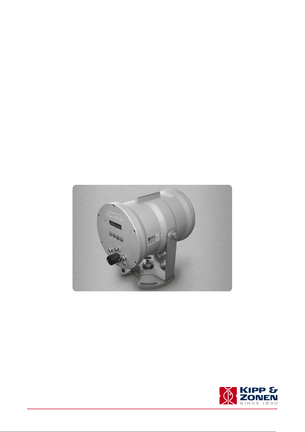
1.1 Product overview
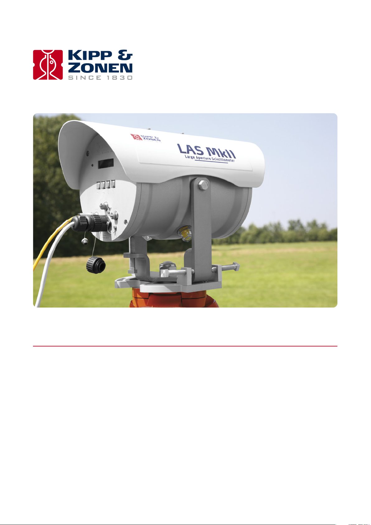
The LAS MkII Large Aperture Scintillometer is an optical instrument with a 150 mm diameter beam that is designed for measuring
2
the path-averaged structure parameter of the refractive index of air (C
the supplied 100 mm diameter aperture restrictors are fitted, the path length can be from 100 m to 1 km
LAS MkII uses a transmitter and receiver horizontally separated by several kilometres to measure intensity fluctuations in the
air known as scintillations. This is the same effect, but of much smaller amplitude, as the ‘shimmering’ of air over very hot or
cold surfaces that causes a mirage.
The scintillations seen by the instrument can be expressed as the structure parameter of the refractive index of air (C
light source of the LAS MkII transmitter operates at a near-infrared wavelength of 850 nm. At this wavelength the observed
scintillations are primarily caused by turbulent temperature fluctuations.
) over horizontal path lengths from 250 m to 4.5 km1. When
n
1
.
2
). The
n
2
Therefore, C
observations of air temperature, wind speed and air pressure to derive the free convection sensible heat flux (H
measurements obtained with the LAS MkII can be combined with temporally and spatially coherent meteorological
n
). An accessory
free
meteorological sensor kit is available for this purpose, which connects to the LAS MKII receiver.
The LAS MkII is self-contained. The system can be locally configured at the receiver with a display and menu keys and has
internal digital signal and data processing and data storage. When the data is exported to the included EVATION software
package running on a computer the surface sensible heat flux (H) can be calculated.
Compared to traditional point measurement systems, the LAS MkII operates at spatial scales comparable to the grid box size of
numerical models and the pixel size of satellite images used in meteorology, hydrology and water management studies. The LAS MkII
has important applications in energy balance and water balance studies, because the surface flux of sensible heat is linked to latent
heat flux (L
E) and evapotranspiration (ET). For these measurements a complete LAS MkII ET System is available.
v
This manual provides information related to the installation, maintenance, calibration, product specifications and applications
of the scintillometer.
If any questions should remain, please contact your local Kipp & Zonen representative or e-mail the Kipp & Zonen customer and
product support department at: support@kippzonen.com
Please go to www.kippzonen.com for information about other Kipp & Zonen products, or to check for any updates to this manual
or software.
1
The maximum usable path length depends upon the atmospheric conditions, the path lengths given are for ‘clear’ conditions (visibility 10-20 km). In general, it is
best to use the scintillometer at full aperture at path lengths down to 250 m, and the aperture restrictors for shorter paths. However, for field-scale measurements
at a range of distances up to 1 km it may be convenient to leave the restrictors fitted.
Instruction Manual - LAS MkII Scintillometer
9
Page 10
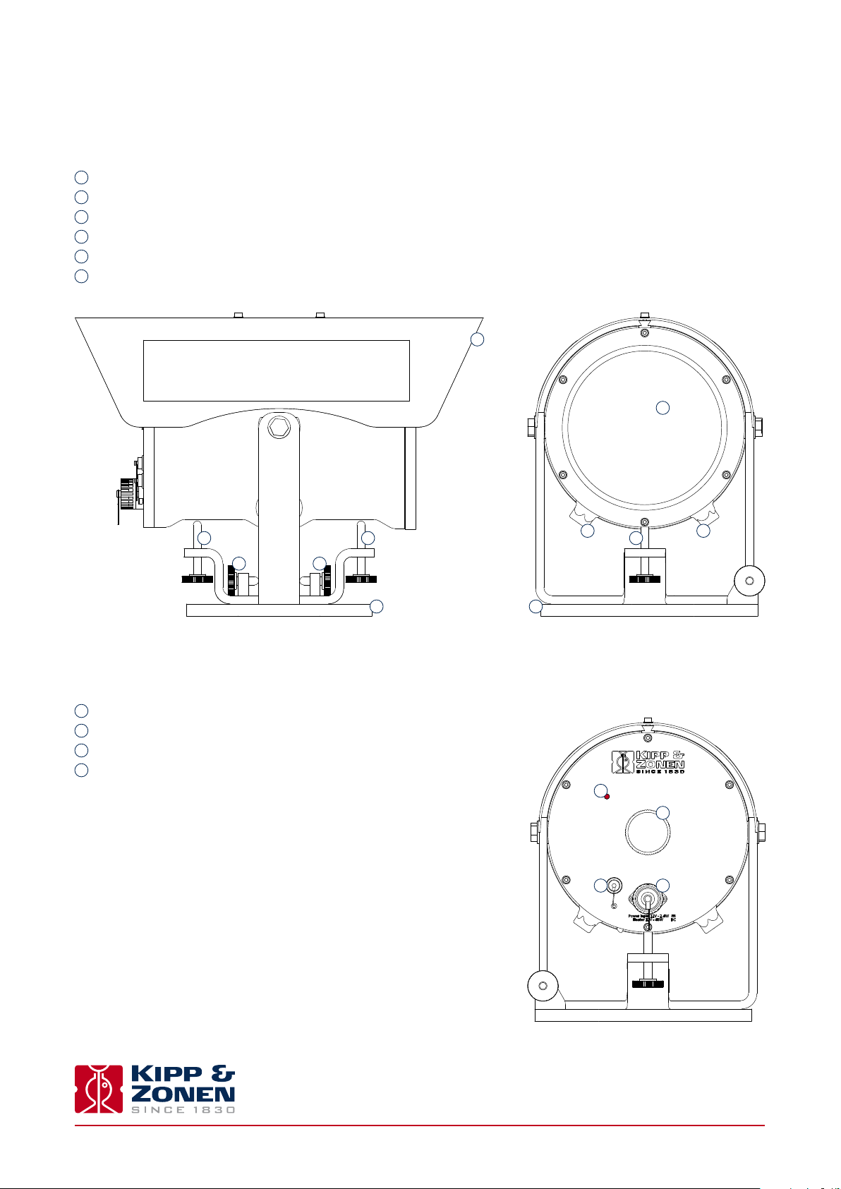
1.2 Key parts of the LAS MkII Scintillometer
1.2.1 Transmitter and receiver
The drawing shows the key common parts of the LAS MkII transmitter and receiver:
1
Sun shield fitted to the mounting for the alignment telescope
2
Tilt (vertical) adjustment screws
3
Pan (horizontal) adjustment screws
4
Transmitter window, with heater and Fresnel lens behind
5
Drying cartridges
6
Baseplate
1
4
2 22
3 3
1.2.2 Transmitter rear panel
The drawing shows the key parts of the LAS MkII transmitter rear panel:
1
Power indicator (red)
2
Transmitter power adjustment knob (remove screw-on cover)
3
Signal output connector (4-pin)
4
Power input connector (12 VDC)
5 5
66
1
2
3 4
Instruction Manual - LAS MkII Scintillometer
10
Page 11

.
1.2.3 Receiver rear panel
The drawing shows the key parts of the LAS MkII receiver rear panel:
Display
1
2
Power and status indicator (green)
3
Menu navigation keys
4
Meteorological sensor kit connector (8-pin)
5
Analogue signal connector (4-pin)
6
Power input connector (12 VDC)
7
Digital interface connector (8-pin)
12
3
4
7
5
6
Instruction Manual - LAS MkII Scintillometer
11
Page 12

Instruction Manual - LAS MkII Scintillometer
12
Page 13
2. Installation
.
Please follow the instructions in this section carefully for the mechanical and electrical installation of the LAS MkII scintillometer.
Do not turn on power to the transmitter or receiver until instructed to do so.
Ensure that fixings and mountings are securely tightened when instructed to do so.
2.1 Included with the product
Check the contents of the shipment for completeness (see below) and note whether any damage has occurred during transport. If
there is damage, a claim should be filed with the carrier immediately. In the case of damage and/or the contents are incomplete,
contact your local Kipp & Zonen representative or e-mail the Kipp & Zonen customer and product support department at:
support@kippzonen.com
Note The LAS MkII is rugged, but it contains sensitive optical and electronic parts. Please keep the original packaging
to safely transport the scintillometer to measurement sites or for other shipments.
The following items are included with the LAS MkII scintillometer:
LAS MkII transmitter with pan and tilt adjuster and baseplate
LAS MkII receiver with pan and tilt adjuster and baseplate
2 × alignment telescope with detachable mounting, adjusted for each transmitter and receiver
2 × sun shield with two fixing screws
2 × 100 mm diameter aperture restrictor with fixing kit, for transmitter and receiver
2 × 10 m cable with 4-pin plug for transmitter signal output and receiver analogue connections
1 x 10 m cable with 8-pin plug for receiver digital communication connections
2 x 10 m cable with 4-pin connector for 12 VDC power input
2 x 3 mm hexagonal Allen keys, for fitting the sun shields
2 x 4 mm hexagonal Allen keys, for fitting the telescopes
1 x CD-ROM containing EVATION software and a pdf file of this LAS MkII instruction manual
8 x spare desiccant packs
Instruction Manual - LAS MkII Scintillometer
13
Page 14
.
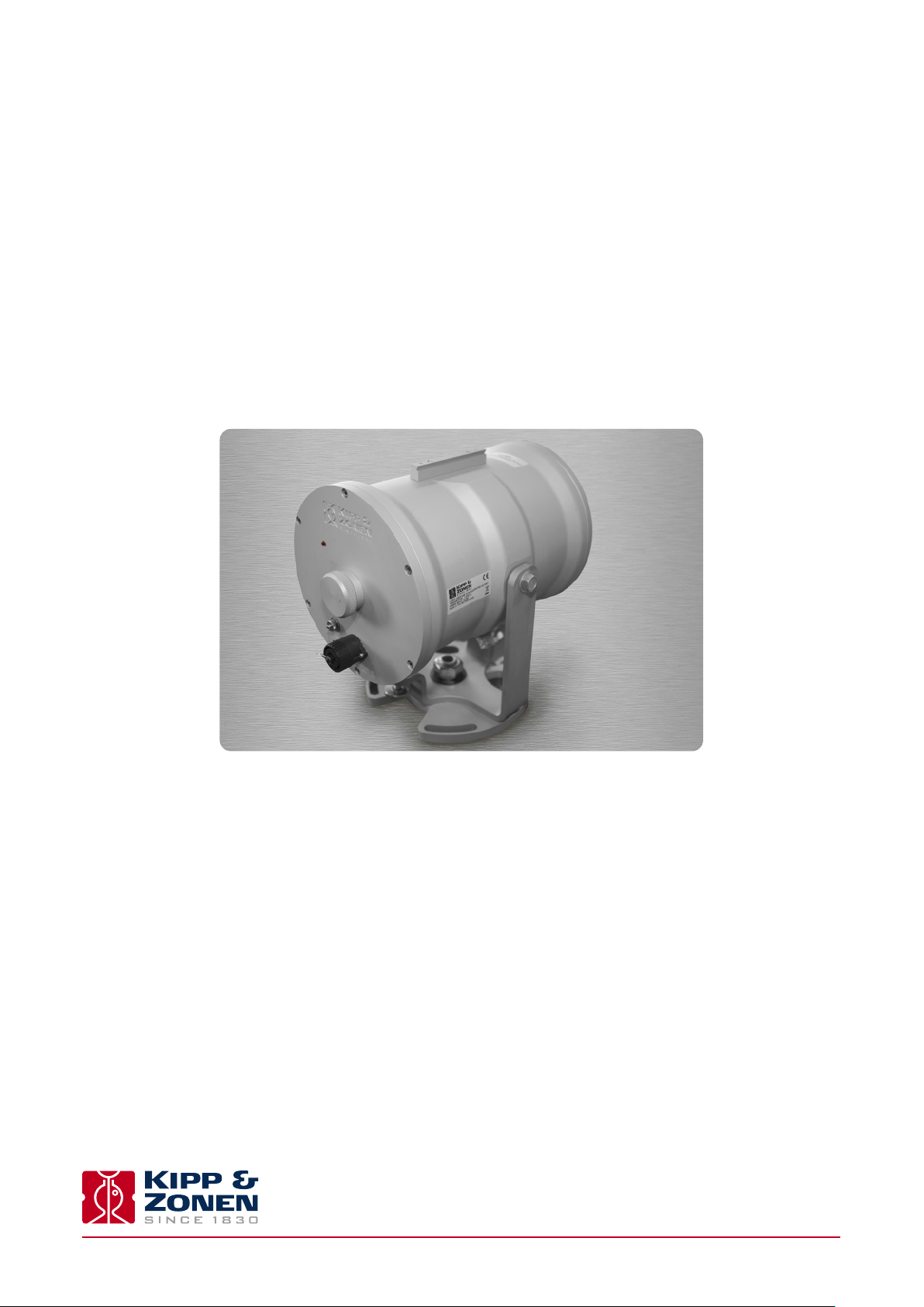
2.1.1 The transmitter
The transmitter housing contains a very efficient, eye-safe LED operating at 850 nm wavelength in the near-infrared region. The
LED mounting is axially adjustable to position it at the focus of a Fresnel collimating lens. The near-parallel beam is output
through a glass window with an aperture diameter of 150 mm. There is a self-regulating heater for the window that can disperse
rain, dew, frost and snow. Electronics pulse the LED at 6.5 - 7 kHz and the drive signals can be monitored on the signal output
connector.
There is a baseplate with rugged and easy to use pan and tilt adjustment. A mounting rail on the top of the housing is used to
fit the alignment telescope or the white heat shield. There are two drying cartridges containing desiccant to keep the transmitter
dry internally.
The transmitter is powered by 12 Volts DC.
Instruction Manual - LAS MkII Scintillometer
14
Page 15
.
2.1.2 The receiver
The beam from the transmitter enters the receiver through a glass window with an aperture diameter of 150 mm. There is a
self-regulating heater for the window that can disperse rain, dew, frost and snow. A Fresnel lens focusses the 6.5 - 7 kHz pulsed
radiation onto a very sensitive large-area photodiode detector with a thin-film optical filter that only transmits radiation in a
waveband around 850 nm, blocking ambient light from reaching the detector. The detector and filter assembly are axially
adjustable to position the detector at the focus of the lens.
Analogue electronics are tuned to the 6.5 - 7 kHz carrier wave and to the scintillation frequency band of 0.2 Hz to 400 Hz. These
signals are rectified and are available at the analogue signal connector. All the remaining electronics are digital. The system can
be locally configured at the receiver with a display and menu navigation keys and has internal signal and data processing and
storage. It can calculate and log Cn2 measurements and, with the accessory meteorological sensor kit connected, the sensible
heat flux (H) can be calculated and stored. External communication is via the digital interface connection.
There is a baseplate with rugged and easy to use pan and tilt adjustment. A mounting rail on the top of the housing is used to
fit the alignment telescope or the white heat shield. There are two drying cartridges containing desiccant to keep the receiver
dry internally.
The receiver is powered by 12 Volts DC.
Instruction Manual - LAS MkII Scintillometer
15
Page 16
.
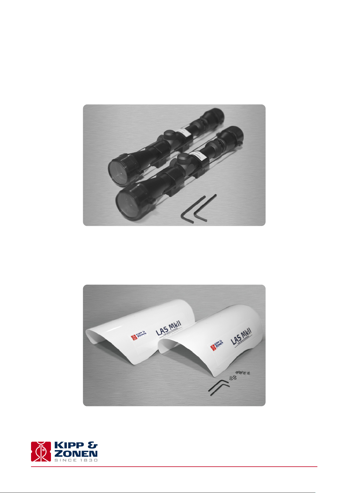
2.1.3 Alignment telescopes
Each transmitter and receiver has a telescope, individually adjusted to align with its optical axis, and each telescope is labelled
accordingly. These telescopes attach by clamps to mounting rails on the tops of the transmitter and receiver housings and enable
alignment of the transmitter and receiver at long path lengths. They are not completely weatherproof and should be removed after
alignment and replaced by the sun shields. A 4 mm hexagonal Allen key is supplied for the mounts of each telescope.
2.1.4 Sun shields
After alignment of the transmitter and receiver the telescopes should be removed and replaced by the sun shields. These are each
attached by two screws to mounting rails on the tops of the transmitter and receiver housings. A 3 mm hexagonal Allen key is
supplied for the fixing screws of each sun shield.
Instruction Manual - LAS MkII Scintillometer
16
Page 17
.
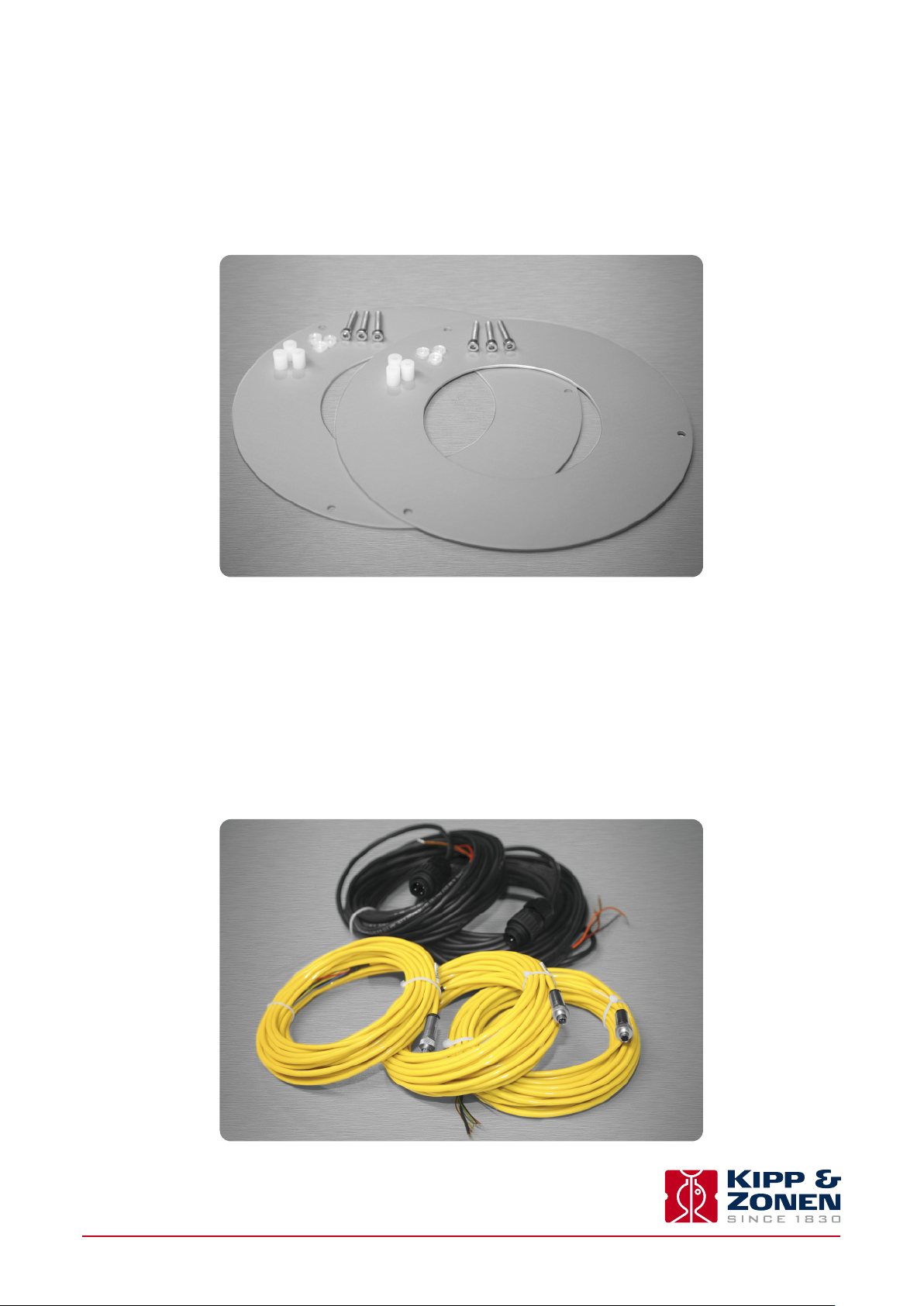
2.1.5 Aperture restrictors
The full beam aperture of 150 mm enables operation over path lengths from 250m to 4.5 km, depending upon the atmospheric
conditions. For shorter path lengths, from 100m to 1 km, restrictors with apertures of 100 mm are fitted in front of the windows of
the transmitter and receiver.
2.1.6 Power cables
Two 10 m long cables with 4-pin waterproof plugs are provided for the transmitter and receiver 12 Volt DC power inputs.
2.1.7 Signal cables with 4-pin plugs
Two 10 m long cables with 4-pin waterproof connectors are provided. One for the transmitter signal outputs, the other for the
receiver analogue signal connection.
2.1.8 Signal cable with 8-pin plug
One 10 m long cable with an 8-pin waterproof plug is provided for the receiver digital interface connection.
Instruction Manual - LAS MkII Scintillometer
17
Page 18
.
2.1.9 Allen keys
Two 3 mm hexagonal Allen keys are supplied for fitting the transmitter and receiver telescopes and two 4 mm hexagonal Allen keys
for fitting the sun shields.
2.1.10 CD-ROM
The supplied CD-ROM contains the EVATION software package and this manual as a pdf file.
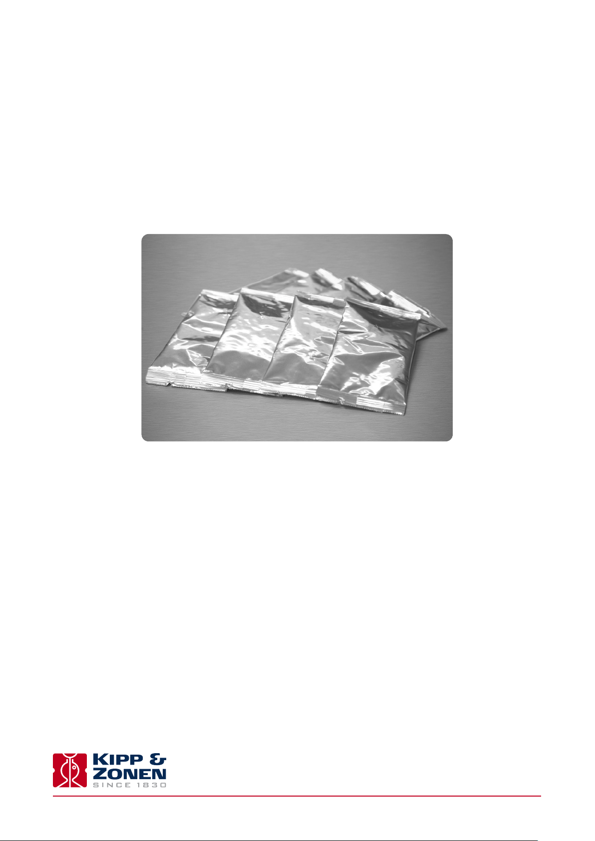
2.1.11 Desiccant packs
Eight spare packs of self-indicating silica gel desiccant are supplied for the drying cartridges of the transmitter and receiver.
2.2 tools required
In addition to the items supplied with the LAS MkII scintillometer, the following equipment is required for performing the installation:
• At least two people
• Stable mounting bases for the transmitter and receiver or tripods
• Printed copy of the manual, from the supplied CD-ROM
• Tape measure for determining the installation height
• 2 x radios or mobile ‘phones for communication between transmitter and receiver operators
• 2 x sets of mounting bolts and suitable wrenches
• 2 x sources of 12 Volts DC power
Instruction Manual - LAS MkII Scintillometer
18
Page 19
2.3 Location and support base
When choosing the location for scintillometer measurements care has to be taken that certain requirements are met.
2.3.1 Path orientation and avoiding direct sunlight
Avoid locating the transmitter and receiver where direct sunlight may be in their views. The Fresnel lenses will focus the light onto
the transmitting LED and the receiving optical filter and photodiode and there is a risk of damage due to overheating.
It is recommended to select a path that is approximately parallel to the Earth’s surface (i.e. horizontal) and has a north-south
orientation to avoid any problems caused at low sun angles. If this is not possible, pick an orientation where some obstruction in
the background (buildings, trees) blocks the direct sun.
Direct sunlight close to the optical axes of the transmitter and receiver may permanently damage optical parts.
In order to maximise the footprint of the measurement, it is recommended to select a path between the transmitter and receiver
which is perpendicular to the predominant wind direction.
Ensure that the optical path between the transmitter and receiver is free of any obstructions.
2.3.2 Minimum installation height to prevent saturation
When the scintillation intensity rises above a certain limit the theory, on which the scintillation measurement method is based,
2
is no longer valid. When this occurs, the relationship between the measured amount of scintillations (σ
2
parameter of the refractive index of air (C
In order to prevent saturation, C
2
must stay below a certain saturation criterion (S
n
only under weakly scintillating conditions. The dependence of C
measurement height (z
) and the path length (L) can be written as follows:
LAS
C
) fails. This phenomenon is known as saturation.
n
), i.e. the scintillometer can measure well
max
2
(λ, D, z
n
2
on the optical wavelength (λ), the aperture diameter (D), the
n
, L) S
LAS
max
The path length and the measurement height are the only variables that can be adjusted in order to keep C
) and the structure
lnI
2
below the saturation
n
criterion. A scintillometer installed at a height close the Earth’s surface; will see more scintillations than a scintillometer
installed high above the surface. As the path length increases more scintillation will be observed.
.
This means that over long distances (several kilometres) the scintillometer must be placed high above the surface in order to
prevent saturation. Over shorter distances (several hundred meters) the scintillometer can be installed closer to the surface.
2
Over dry areas the surface sensible heat flux is large, resulting in higher C
heat flux is small.
The graphs below show the minimum height of the LAS MkII for different surface conditions as a function of the path length. The
area above the curves in the figure is the so-called non-saturation zone. Below the curves saturation will occur. Based on the
user’s preferred path length, and the surface conditions of the area of interest, the user must install the LAS MkII scintillometer
at a height that lies in the non-saturation zone.
values than over wet surfaces where the sensible
n
Instruction Manual - LAS MkII Scintillometer
19
Page 20
Full 150 mm aperture
60
50
40
30
Height LAS [m]
20
10
0
0 500 1000 1500 2000 2500 3000 3500 4000 4500
Restricted 100 mm aperture
7
6
5
4
LAS [m]
h = 50 W/m²
h = 100 W/m²
h = 150 W/m²
h = 250 W/m²
h = 300 W/m²
h = 400 W/m²
No saturation
Saturation
Path length LAS [m]
h = 50 W/m²
h = 100 W/m²
h = 150 W/m²
h = 250 W/m²
h = 300 W/m²
h = 400 W/m²
No saturation
0.1 m-
3
Height
2
1
Saturation
0
0 100 300 500 700 900200 400 600 800 1000
Path length
0.1 m-
LAS [m]
.
For example, a LAS MkII installed over a relatively wet area (h ~ 100 W/m²) and a path length of 3 km must be installed at a
height of at least 12 m.
Ensure that the LAS MkII is operating in the ‘non-saturation’ zone.
Instruction Manual - LAS MkII Scintillometer
20
Page 21
.
2.3.3 Effective beam height
Determine the effective height of beam of the LAS MkII (z
from the structure parameter data is very sensitive to the height (see Appendix A). When the area is relatively flat and the beam
is parallel to the surface the effective height is easy to determine (z
The path-weighting function is symmetrical and bell-shaped having a centre maximum and tapering to zero at the transmitter
and receiver end. This means that the LAS MkII is most sensitive in the middle of its path. For situations where the area is not
flat, or for slanted paths, it is recommend to measure the height of the beam at several points along the path.
The figure below shows how the weighting function must be used in order to estimate the precise height of the beam above the
surface for non-flat areas. The effective height calculator in the EVATION software package can be used to find the effective
height, as described in Appendix E. For more information see Hartogensis et al, 2003
) along the path precisely. The surface sensible heat flux (H) derived
LAS
transmitter
= z
receiver
= z
).
LAS
1
.
70
60
Transmitter
50
Receiver
surface
beam - LAS
40
Height [m]
30
20
10
weighting function - LAS
0
0 0.1 0.2 0.3 0.4 0.5 0.6 0.7 0.8 0.9 1
Normalised position [-]
0.015
0.01
Weight [%]
0.005
0
The graphs above illustrate a LAS MkII path (beam) over a non-flat area. Based on the elevation map (surface) and the LAS
path-weighting function, an effective beam height of 46 m was calculated.
1
Hartogensis, O.K., Watts, C.J., Rodriguez, J-C. and De Bruin, H.A.R.: 2003, ‘Derivation of an Effective Height for Scintillometers: La Poza Experiment in Northwest Mexico’, J. Hydro-Meteorol. 4, 915-928.
.
2.3.4 Operation in the constant flux layer
2
In order to derive the surface fluxes of sensible heat from the scintillometer measurements (C
) we use the Monin-Obukhov Similarity
n
Theory (MOST) (see Appendix A). MOST is widely used in meteorology and is usually applied to the Surface Layer (SL) and hence is
sometimes called the Surface Layer Similarity. The SL is roughly the lowest 10% of the Planetary Boundary Layer (PBL).
Instruction Manual - LAS MkII Scintillometer
21
Page 22

.
The PBL is directly influenced by the earth’s surface and its depth varies between roughly 100m and 2 km. In general the PBL
increases during the day, when the Earth’s surface is heated by the sun, and decreases again during the night. Within the SL the
variation of fluxes (such as the sensible heat flux H and latent heat flux L
value at the surface.
Therefore, fluxes measured at a certain elevation in the SL can be considered as being representative of the exchange processes
occurring between the Earth’s surface and the atmosphere above. The SL can be further divided into the Roughness Sub-layer
(RS), influenced by the structure of the roughness elements (e.g. plants, trees, buildings etc.), and the Constant Flux Layer
where fluxes are assumed to be horizontally and vertically constant (due to turbulent mixing). This means that measurement
techniques that apply MOST for estimating surface fluxes can be applied only in the Constant Flux Layer.
Therefore the LAS MkII must be installed at a height such that it is located above the Roughness Sub-layer and is measuring
within the Constant Flux Layer.
The depth of the SL typically varies between 20 m and 100 m. The upper level strongly depends on the diurnal cycle of surface
heating and cooling and the presence of clouds. Like the PBL, the SL increases during the day as the surface is heated by the sun
and is maximum at sunset (~100 m), before it decreases again due to cooling of the surface at night (~20 m).
The height of the Roughness Sub-layer, and thus the lower level of the Constant Flux Layer, depends strongly upon the size, form
and distribution of the roughness elements. Usually, over tall vegetation, the height of the Roughness Sub-layer is taken to be
equal to three times the obstacle height (or roughness elements h).
E) is negligible with respect to the magnitude of their
v
In case the estimated height of the Roughness Sub-layer is below the minimum height to avoid saturation, use a height that
ensures the LAS MkII is in the non-saturation zone.
Ensure that the LAS MkII is measuring in the Constant Flux Layer and in the non-saturation zone.
Note More detailed information about the theory of the scintillation technique can be found in Appendix A.
Note A list of symbols and abbreviations can be found in Appendix B.
Instruction Manual - LAS MkII Scintillometer
22
Page 23
2.4 Mounting
The LAS MkII can only function properly when the transmitter and receiver are precisely optically aligned. By mounting the
scintillometer on a stable support, signal loss and regular re-alignment procedures will be avoided. Vibrations in the mounting
2
structure must be prevented, which can lead to overestimated C
bend and vibrate in the wind.
Mount the LAS MkII transmitter and receiver on stable and vibration-free supports.
Adjustable tripods are only suitable for short-term measurements. Where they are not on hard surfaces, a board should be used
to prevent the tripod legs sinking in and affecting the beam alignment.
If tripods are used, ensure that they cannot easily fall over and possibly damage the transmitter or receiver.
The pan and tilt adjusters of the transmitter and receiver have a baseplate. This has a central M16 thread to fit the mounting
bolts of industrial tripods, such as the accessory adjustable heavy-duty tripod package for the LAS MkII.
The baseplate has 4 slots for 10 mm bolts, on 184.2 mm diameter, which can be used for fixing the transmitter and receiver to a
customer-supplied support or to the accessory Kipp & Zonen tripod floor stand and/or height extension tube. The bottom view
of the baseplate is shown below.
values. This particularly applies to masts or towers that can
n
M16 threaded hole
Mounting slots for
4 x 10 mm bolts on
184.2 mm diameter
Instruction Manual - LAS MkII Scintillometer
23
Page 24
2.5 Electrical and data connections
There are two waterproof connectors located on the rear panel of the transmitter and four on the rear panel of the receiver.
2.5.1 Power connector
The transmitter and receiver are each provided with a 4-pin waterproof plug fitted to a 10 m long cable that is terminated in
tinned wires, for 12 Volts DC (nominal) power to the instrument and heater.
Transmitter and receiver power connector and cable
Pin number Wire colour Function Value
1 red instrument power + 9.6 to 18 VDC
2 orange heater power + 9.6 to 18 VDC
-
3 brown heater return
4 black instrument return
shield thick black cable screen housing ground
The LAS MKII transmitter and receiver must be grounded through the shield of the power connector (also connected
to pin 4) for protection against lightning and electrical interference.
0 V
-
0 V
The LAS MKII transmitter and receiver power inputs should be protected by fuses.
Instrument power +, 1 A normal or slow-blow type. Heater power +, 4 A slow-blow type.
2.5.2 Transmitter signal output connector
The transmitter is provided with a 4-pin plug for signal outputs, fitted to a 10 m long yellow cable that is terminated in tinned wires.
Transmitter signal connector and cable
Pin number Wire colour Function Value
1 red not connected
2 blue 6.5 - 7 kHz pulse + 0 to 8 V
0.5 duty cycle
3 green 6.5 - 7 kHz LED pulse + 0 to 2 V
0.5 duty cycle proportional to LED
power setting
-
4 yellow signal
shield thick black cable screen housing ground
0 V
Instruction Manual - LAS MkII Scintillometer
24
Page 25

.
2.5.3 Receiver Analogue signal connector
The receiver is provided with a 4-pin plug for analogue signal outputs, fitted to a 10 m long yellow cable that is terminated in
tinned wires.
Receiver analogue signal connector and cable
Pin number Wire colour Function Value Impedance
2
1 red Log UC
10
2 blue 6.5 to 7 kHz AC 0 to 1 V RMS 120 Ω
carrier signal + 100 % = 152 mV RMS 4700 pF
3 green demodulated carrier 0 to 2 V 680 Ω
signal (U
4 yellow signal
shield thick black cable screen housing ground
2.5.4 Receiver digital interface connector
The receiver is provided with an 8-pin waterproof plug for the digital communication interface, fitted to a 10 m long yellow cable
that is terminated in tinned wires.
signal + 0 to 2 V 680 Ω
n
) + 100 %= 606 mV 4700 pF
demod
-
0 V
-17
to 10
-12 m-2/3
4700 pF
Two communication modes can be selected, RS-232 or 4-wire RS-422 (default). The desired mode can be selected using the LAS MkII
configuration menu or by the control software.
Receiver digital interface connector and cable
Pin number Wire colour RS-232 function RS-422 function
1 red RXD RXD- (A)
2 blue CTS RXD+ (B)
3 green DSR do not connect
4 yellow RTS TXD+(Z)
5 grey TXD TXD- (Y)
6 brown DTR do not connect
7 white DCD do not connect
8 black digital ground digital ground
shield thick black cable screen cable screen
For permanent connection to a computer always use optically or galvanicly isolated adapters or converters at the
computer serial port to protect against damage caused by lighting.
Instruction Manual - LAS MkII Scintillometer
25
Page 26
.
2.5.5 Receiver meteorological sensor kit connector
The 8-pin connector marked ‘Sensors’ must only be used with the accessory meteorological sensor kit. The 12 VDC
output must not be used to supply other equipment.
Receiver meteorological sensor kit connector
Pin number Wire colour Function Value
1 red not connected
2 blue not connected
3 green not connected
4 yellow power supply 12 VDC output
for sensor kit do not ground!
5 grey temperature input 4 to 20 mA
6 brown air pressure input 4 to 20 mA
7 white wind speed input 4 to 20 mA
8 black sensors ground 0 V
shield thick black cable screen housing ground
The accessory meteorological sensor kit is supplied pre-wired with a 10 meter long yellow cable and waterproof connector and
will be automatically powered and recognised when plugged into the LAS MkII receiver.
Wind speed
Temperature
Pressure
Do not connect a computer to the sensor connector using the digital interface plug and cable. The 12 V power
output for the sensors may damage the computer serial port.
Junction Box
Instruction Manual - LAS MkII Scintillometer
26
Page 27

2.6 Aperture restrictors for short range applications
In case the LAS MkII is required to operate over short distances the aperture diameter of the transmitter and receiver can be
reduced to 100 mm using the supplied restrictors. The LAS MkII can then be used over path lengths from 100 m to 1 km.
To fit the restrictors proceed as follows and shown in the diagram below:
1. Remove 3 of the 6 retaining screws of the transmitter and receiver windows
2. Replace the screws by the nylon spacers
3. Secure the restrictors using the M4 x 25 mm cap-head screws and nylon washers
When using the restrictors, remember to set the aperture values in the LAS MkII configuration menu to 100 mm.
As the beam diameter becomes smaller so does the beam divergence. This means that the alignment of the 100 mm
LAS MkII may be more critical than for the full-beam 150 mm LAS MkII. It is recommended to use very stable
mounting constructions.
Cap screw M4 x 25 (3x)
Nylon washer (3x)
Nylon spacer (3x)
Instruction Manual - LAS MkII Scintillometer
27
Page 28

2.7 Using the display and key-pad
The waterproof display and menu navigation keys located on the rear panel of the LAS MkII receiver allow for complete instru-
ment configuration and control without the need for additional computers, cables and software. This section describes the basic
procedure for navigating through the menus, changing and confirming settings.
Note The complete menu structure of the LAS MkII scintillometer can be found in Appendix C.
Navigating through the LAS MkII menu structure is very straight-forward using the keys.
> MENU
1. RealTime Data
The keys are used to scroll through the (sub-) menus or to select or enter a value:
Scroll mode:
Up key Select next menu item
Down key Select previous menu item
Left key Go one menu level back
Right key Select displayed menu item
Edit mode
Up key Increment digit
Down key Decrement digit
Left key Select previous digit
Right key Select next digit
Confirm (edit mode)
Display shows Confirm Entry - Yes
Up or down key Cycles through options; Yes, No, Quit
Right key Completes selected action:
Yes - confirm changes and go back to menu
No - cancel and go back to edit mode
Quit - exit edit mode without changes
Instruction Manual - LAS MkII Scintillometer
28
Page 29

.
For example to change the path length setting from 110.0 m to 1250.0 m the following actions need to be performed:
2. path length
0110.0 m
2. path length
1110.0 m
2. path length
1110.0 m
2. path length
1210.0 m
2. path length
1210.0 m
Press 4x (to increment from 1 to 5)
2. path length
1250.0 m
Press 2x (to move cursor all the way to the right)
confirm entry
yes
confirm entry
NO
confirm entry
quit
To confirm changes and go back to menu
To cancel and go back to edit mode
To exit edit mode without changes
In order to keep this manual as concise as possible, this process will be shortened in the following way:
Main Menu → 2. Configuration → 1. Installation → 2. Path length → 1250.0 m → Confirm
Note To reduce power consumption and increase life-time, the receiver display is turned off if no keys are pressed for
4 minutes. Pressing any key turns the display on again.
Instruction Manual - LAS MkII Scintillometer
29
Page 30

2.8 Configuration for measurement
The table below shows the sub-menus contained within Menu 2, Configuration. These sub-menus require setting up before, or
during, installation. To configure the LAS MKII receiver before installation refer to the ‘power up receiver’ section 2.9.4.
Note The complete menu structure of the LAS MkII scintillometer can be found in Appendix C.
Sub-menu Sub-menu item Function Range Default
1. Installation 1. Aperture Set or show effective diameter 0 to 399.9 mm 149 mm
2. Path Length Set or show path length 0.0 to 7999.9 m 1184 m
3. Install Height Set or show installation height 0.0 to 4999.9 m 1.5 m
4. Z.Displ.Height Set or show zero displacement height 0.01 to 9.999 m 0 m
5. Bowen Ratio Set or show Bowen Ratio 0.01 to 9.999 2
6. Signal Gain Show signal strength and set gain 1x, 2x, 4x 1
7. Set Defaults Restore default configuration 0 = No, 1 = Yes 0 = No
8. << Back Back to higher menu
2. Advanced 1. Rel Humidity Set or show relative humidity 0 to 99.9% 50%
2. Heat capacity Set or show heat capacity of air 500.0 to 1999.9 1000
3. Bowen Ratio Set or show Bowen Ratio 0.01 to 9.999 2
4. Empir.Constant Set or show empirical constant 0 to 9.999 0.48
5. << Back Back to higher menu
3. Sensors 1. Air Temp Set or show air temperature -39.9 to 49.9 °C +17 °C
2. Air Pressure Set or show air pressure 0 to 1100 mBar 1012 mBar
3. Wind speed Set or show wind speed 0 to 40.0 m/s 2.2 m/s
4. Device Temp Set or show receiver temperature -39.9 to 49.9 °C N/A
5. << Back Back to higher menu
4. DataLogger 1. Set Date Set date yy/mm/dd ECT
2. Set Time Set time hh:mm:ss ECT
3. Wakeup Time Set or show time start measure & log hh:mm 99.99=Off
4. Sleep Time Set or show time stop measure & log hh:mm 99.99=Off
5. Log Interval Set data average and log interval 0 to 29999 s 600 s
6. Send Interval Set send interval of data to computer 0 to 29999 s 0=Off
7. << Back Back to higher menu
5. Interface 1. Set Default Restore default configuration Com 1
2. BaudRate Set or show baud rate 1200 to 38400 4800
3. Parity Set or show parity 0=none, 1=odd, 2=even 0
4. Databits Set or show number of databits 7 or 8 8
5. Interface Type Set or show interface type RS-232-C or RS-422 422
6. DeviceID Set device address 0 to 255 255
7. Restart Restart the receiver
8. << Back Back to higher menu
Note The Sensor sub-menu default values are used when the meteorological sensor kit is not connected. These values
can be changed by the user, within the ranges shown.
Note If a BaudRate is entered different to those listed, the receiver will select the nearest valid value.
Valid interface types are 232 and 422, if another number is entered the port will switch off.
Instruction Manual - LAS MkII Scintillometer
30
Page 31

.
2.8.1 Setting parameters to measure C
2
C
is measured using the following general algorithm:
n
2
n
2
C
n
= 1.12 σ
7/3L-3
2
D
lnI
Where; D is the aperture diameter of the LAS MkII, L is the distance between the transmitter and the receiver (the path length)
2
and σ
the measured variance of the natural logarithm of intensity fluctuations.
lnI
The parameters for aperture and path length must be set in the receiver.
Note Set the Aperture to the value stated on the Test and Final Inspection Certificate supplied with the instrument. The
typical setting is 149 mm.
2.8.2 Setting parameters to measure sensible heat flux
2
From C
data, together with wind speed, temperature, and an estimate of the topology and the displacement height; the surface
n
sensible heat flux (H) can be determined from by solving equations iteratively. See Appendix C for further information.
2
In addition to the parameters for measurement of C
the following additional parameters are required to measure surface sensi-
n
ble heat flux (H):
• Installation height
• Zero Displacement Height
• Bowen Ratio
• Temperature
• Pressure from meteorological sensor kit when connected
• Wind Speed
• Roughness Length
The surface sensible heat flux (H) can be calculated by a computer using the supplied EVATION software package, the data from
the LAS MkII and meteorological sensor kit and by inputting other parameters, such as the roughness length.
However, for most day-time (unstable) conditions and when the LAS MkII is installed relatively high above the surface (z
LAS MkII
> 20 m) the contribution of the friction velocity is relatively small. For these conditions the free convection method can be
applied.
Note that the free convection sensible heat flux (H
) calculated by this method is not as accurate as the standard method for H
free
because it does not allow for surface topography (roughness length, etc.).
See Appendix C for further information.
When the meteorological sensor kit is connected the LAS MkII can internally calculate and log the free convection sensible heat
free
).
flux (H
2.8.3 External sensors
When the meteorological sensor kit is connected the correct factory sensitivities and ranges are automatically selected.
When the kit is not connected, fixed values typical of the measurement location can be entered in sub-menu 3 of the configuration menu.
Instruction Manual - LAS MkII Scintillometer
31
Page 32

.
2.8.4 Data Logger
Configure the following data logger settings; date, time, sleep time, wakeup time, log-interval and send interval.
The wakeup time defines the start of the operational mode. When the operational mode is active the LAS is measuring and
logging data; the receiver heater is turned on when the temperature of the receiver is below the ‘operating temperature’ in the
heater menu.
The sleep time defines the start of the low power ‘sleep’ mode, during which there is no measurement and the receiver heater is
turned on only when the temperature of the receiver is below the ‘standby temperature’ in the heater menu.
The log interval defines the interval over which measurements will be averaged and then stored in the internal flash data memory.
The send interval defines the interval at which the current data values will be sent automatically to a computer.
2.8.5 Interface
Configure the following interface settings; baud rate, parity, data bits and interface type.
Instruction Manual - LAS MkII Scintillometer
32
Page 33

2.9 Installation and optical alignment
The alignment of the LAS MkII at the measurement site is an iterative process for establishing the optimum signal strength for
horizontal line-of-sight transmission. The different steps are summarized below. We recommend practicing the alignment
procedure at a short range (~ 250 m) before installation at longer distances.
The transmitter and receiver can be rotated around both vertical and horizontal axes. The coarse horizontal alignment (pan) can
be done by rotating the transmitter and receiver before the bolt(s) fixing the baseplate to the supporting structure is (are)
tightened. Fine pan adjustment is done with the two horizontal adjustment screws. For the vertical alignment (tilt) two vertical
adjustment screws are provided, one at the front and one at the rear.
Vertical fine adjustment (tilt)
Horizontal fine adjustment (pan)
2.9.1 Preparation for installation
Two people should carry out the alignment, one at the receiver and one at the transmitter. They must be able to communicate
either by radio, walkie-talkies or mobile telephones.
Note The final alignment should be carried out under conditions of clear or very clear visibility, i.e. visibility > 10 km.
The table below shows the typical variation in receiver signal strength over a path length of 3000 m for a nominal transmitter
power and receiver signal gain setting.
Visibility class Visibility range Nominal signal
Very clear 20 to 50 km 175 to 225 %
Clear 10 to 20 km 125 to 175 %
Hazey 4 to 10 km 75 to 125 %
Instruction Manual - LAS MkII Scintillometer
33
Page 34

.
2.9.2 Installing the transmitter and receiver
1. Install the transmitter and receiver of the LAS MkII at their selected positions.
2. The bolts used to fix the baseplates to the tripods or other supporting structures are fastened by hand, so that the transmitter
and receiver can still be turned around their vertical axes.
3. Clamp the telescopes to the rails on the tops of the transmitter and receiver using the 4 mm hexagonal Allen keys. Note that
the telescopes are factory-aligned for each transmitter and receiver and are marked appropriately with either ‘Transmitter’
or ‘Receiver’.
4. Adjust the transmitter both horizontally (pan) and vertically (tilt) such that the crosshairs of the telescope are centred on the
receiver window. Tighten the bolt(s) fixing the baseplate to the supporting structures (further adjustments can be done with
the pan fine adjustment screws).
5. Carry out the same procedure for the receiver relative to the transmitter.
2.9.3 Power up transmitter
1. Connect a suitable 12 VDC power supply to the transmitter and switch on the power. The red power indicator on the transmitter
rear panel will illuminate.
2. Unscrew the cover of the power adjustment knob and initially set the 10-turn dial (scaled from 0 to 1000) to maximum.
2.9.4 Power up receiver
1. Connect a suitable 12 VDC power supply to the receiver and switch on the power. The green power and status indicator on the
rear panel provides information on the operation of the LAS MkII receiver, as in the following table.
Green indicator function Status
Green indicator function Status
(0.2 sec on 0.8 sec off) The instrument is operational
Normal blinking
Normal blinking
Fast blinking
Fast blinking
Slow blinking The boot loader is running
Slow blinking The boot loader is running
Always on The boot loader is halted,
Always on The boot loader is halted,
no application is running
no application is running
Always off The power is switched off,
Always off The power is switched off,
the instrument has a hardware error,
the instrument has a hardware error,
or the supply voltage is too low
or the supply voltage is too low
(0.2 sec on 0.8 sec off) The instrument is operational
(0.2 sec on 0.2 sec off) A hardware error was detected
(0.2 sec on 0.2 sec off) A hardware error was detected
2. The display on the rear panel of the receiver will cycle through the following start-up messages (examples are shown):
• The serial number and production document
LASRX 12:0001
120-0371500-4
• The software release and hardware release
SOFTW.REL 2.00
HARDW.REL 1.2
• The communication parameters (interface type, baud rate, data bits, parity)
COM1 - RS422
4800/8/N
• The successful start-up message
Start Completed
NO ERRORS
Or ‘Check 12V Heater’ (this is only a warning that the heater is not set, it is not an error)
Instruction Manual - LAS MkII Scintillometer
34
Page 35

.
If a hardware error message occurs, try turning off the power and the restarting the receiver. If the error persists,
make a note of the code and contact support@kippzonen.com
3. A configuration error message will be displayed if one or more of the configuration parameters stored in the memory are not
correct. The following configuration error messages are defined:
Checksum Error
No Configuration
Setup Error
No Configuration
The SerialNumber
is not set
Configuration
error
the logfile is
cleared
The Idle mode is
set
the instrument
is idle
Note More detailed information about configuration errors and how to clear them is given in Appendix D.
1. At the receiver ensure that the LAS MKII is configured as described in section 2.8, in particular the path length, installation
height and aperture (100 mm or 149 mm).
2. At the receiver set the signal gain using the navigation keys as follows:
Main Menu → 2. Configuration → 1. Installation → 6. Signal Gain
Initially set the signal gain to 1 (this is the default value).
3. Return to the main menu and select
Main Menu → 1. View RealTime → 1. Signal Level
2.9.5 Transmitter optical alignment
Note It is very important to follow this procedure carefully because the data is not reliable when the edges of the beam
are to close to the receiver or transmitter aperture.
1. The person at the receiver observes the signal level and communicates the values to the person at the transmitter.
2. The person at the transmitter first slowly turns the transmitter horizontally (pan) left and right using the adjustment screws
until the maximum signal strength (as given by the person at the receiver) is reached.
3. There should be a ‘plateau’ region of approximately the same signal strength between the horizontal edges of beam. Find the
mid-point of this region, which will be the centre of the beam.
4. The transmitter then needs to be slowly adjusted vertically (tilt) up and down using the adjustment screws to find the mid-point
maximum signal strength, as in step 3.
5. The concept of the maximum signal ‘plateau is shown in the figure on the next page.
6. If the receiver signal strength is more than 200 % reduce the transmitter power for a reading of about 100 %. Optimise the
horizontal and vertical alignment for the maximum signal strength in the middle of the ‘plateau’ region. Each time the signal
strength is more than 200 % reduce the transmitter power for a reading of about 100 %.
Instruction Manual - LAS MkII Scintillometer
35
Page 36

.
7. Repeat steps 2 to 8 until the best transmitter optical alignment is achieved.
8. Tighten the transmitter adjustment screws, checking that the signal strength has not changed.
.
Left Right
Beam width
Center beam
> UDEMOD * 4
Signal level [mV]
0000.0 mV
0
2.9.6 Receiver optical alignment
Note It is very important to follow this procedure carefully because the data is not reliable when the edges of the beam
are too close to the receiver or transmitter aperture.
1. The person at the receiver observes the signal level and optimises the alignment.
2. First slowly turn the receiver horizontally (pan) left and right using the adjustment screws until the maximum signal strength
is reached.
3. As for the transmitter, there should be a ‘plateau’ region of approximately the same signal strength between the horizontal
edges of beam. Find the mid-point of this region, which will be the centre of the beam.
4. The receiver then needs to be slowly adjusted vertically (tilt) up and down using the adjustment screws to find the mid-point
maximum signal strength, as in step 3.
5. If the receiver signal strength is more than 200 % reduce the transmitter power for a reading of about 100 %. Optimise the
horizontal and vertical alignment for the maximum signal strength in the middle of the ‘plateau’ region. Each time the signal
strength is more than 200 % reduce the transmitter power for a reading of about 100 %.
6. Repeat steps 2 to 5 until the best receiver optical alignment is achieved.
7. Tighten the receiver adjustment screws, checking that the signal strength has not changed.
2.9.7 Finalise optical alignment
1. Adjust the transmitter power to give signal strength of 100 - 120 % and lock the knob with the small black tab. Make a note
of the dial setting for future reference.
Note It is possible that at path lengths of 3000 m or greater, and depending upon the visibility, a signal strength of
100 - 120 % is not achievable. The LAS MKII will operate correctly with signal strength of 25% or more. Do not increase
the receiver signal gain, as this also increases the noise and overall measurement performance is not improved.
Instruction Manual - LAS MkII Scintillometer
36
Page 37

.
2. Screw on the cover of the power adjustment knob. Hand-tighten only to avoid damaging the o-ring seal.
2
3. The optical alignment is now complete. Go back to the View RealTime menu and sub-menu 3 (C
). The LAS MkII should now
n
be measuring and logging data according to the configuration set in section 2.8.
.
Note It is possible that the transmitter or receiver is not now aligned with the centre of the crosshairs of its telescope.
This is due to a difference between the operating path length and the range at which the telescopes were adjusted
at the factory. Therefore never rely only on the telescopes during the alignment procedure! If desired, the crosshairs
of the telescopes can be adjusted using the instructions provided with them.
4. The telescopes can now be removed and the sun shields fitted to the transmitter and receiver with the fixing screws and the
3 mm hexagonal Allen keys. Store the telescopes carefully for future use.
Never (re-)align the LAS MkII transmitter and receiver using the telescopes only and do not swap the transmitter
and receiver telescopes. Always use the optical alignment procedure.
To avoid non-linearity of the detector and overload of the electronics, the signal strength is limited to a maximum
of 250 %. Above this the over-range value of 999% is shown.
Instruction Manual - LAS MkII Scintillometer
37
Page 38

Instruction Manual - LAS MkII Scintillometer
38
Page 39

3. Accessories
3.1 Meteorological sensor kit
The kit is supplied as a cross-arm with cables connected to a junction box, which has a 10 m long yellow cable fitted with a
waterproof connector. The junction box contains an air pressure sensor and has a sintered bronze ‘breather’ to the ambient air.
Wind speed and air temperature sensors are provided, which must be secured to the cross-arm (the fixing screws are already
fitted to the cross-arm) and then connected to the cables.
An aluminium pole, 2 m long, is supplied for supporting the cross-arm and junction box.
The meteorological sensor kit will be automatically powered and recognised when plugged into the LAS MkII receiver.
3.2 CVP 1 LAS MkII power supply
This is a weatherproof heavy-duty AC-DC power supply unit for outdoor use. One each is required for the transmitter and
receiver of the LAS MKII.
Wide AC input range, fully protected output 12 VDC at 3.5 A.
Operating temperature range -20 °C to +50 °C.
Pre-wired with 10 m long power output cable and connector for LAS MkII transmitter or receiver, and 5 m long AC power input
cable with IEC female plug.
3.3 Transit case
Foam-lined rugged transit case, for safe transport of LAS MkII. One each is required for the transmitter and receiver.
3.4 Adjustable heavy-duty tripod package
Aluminium folding tripod, adjusts up to 3 m height, includes base-frame for hard surfaces and fixing bolts for LAS MkII. Two
supplied, one each for transmitter and receiver, in a wood carrying case.
3.5 Tripod floor stand
For easy mounting and levelling of the LAS MkII, height 0.45 m. Very stable and rugged. As used with the Kipp & Zonen Brewer
spectrophotometer and 2AP sun tracker. One each is required for the transmitter and receiver.
3.6 Height extension tube
Bolts to the top of the tripod floor stand and extends the mounting height to a total of 1.05 m.
Instruction Manual - LAS MkII Scintillometer
39
Page 40

Instruction Manual - LAS MkII Scintillometer
40
Page 41

4. Software installation and configuration
.
The LAS MkII scintillometer can be configured in two ways; using the built-in display and keypad of the receiver or through the
included EVATION software package. Configuring the receiver using the display and navigation keys has been described in
section 2.8. This section describes the LAS MkII configuration using EVATION.
EVATION allows the LAS MkII user to derive the surface fluxes of sensible heat from recorded scintillometer data and additional
meteorological data, such as air temperature (T), air pressure (P), wind speed (u) and Bowen ratio (β).
If a complete LAS MkII ET System is available EVATION can also calculate the latent heat flux (L
E) and evapotranspiration (ET).
v
4.1 Installing the EVATION software package
4.1.1 System requirements
The minimum computer hardware requirements for EVATION are a 800 MHz Pentium computer running Windows™ XP or
Windows™ 7 (32-bit or 64-bit), 1 GB of RAM, 300 MB of free hard-disk space (excluding LAS MkII data) and a mouse.
4.1.2 Installation procedure
In order to install the EVATION software package, please select and run the file ‘EvationSetup.exe’ which is located on the CD-ROM
supplied with the instrument. The installer program will guide you through the installation process.
Note ‘Administrator’ rights on the computer may be required to install the software.
4.1.3 Using EVATION for the first time
When EVATION is started for the first time, the following screen is shown.
Since there is no previous LAS MkII data available, the software must be configured as follows.
Instruction Manual - LAS MkII Scintillometer
41
Page 42

.
4.1.4 Selecting a data folder
EVATION stores all scintillometer data and processing settings in a predefined folder structure.
Folder name Function
input All measurement data should be stored here
Data retrieved using the LAS MkII digital interface connection is placed here
output Repository of processed data
config Configuration setting files are stored in this folder
auxiliary Any intermediate or temporary data required by EVATION is stored in this folder
The first requirement for working with EVATION is selecting, or creating, a user-defined folder in which the above folder
structure is created.
In the main screen select the tab ‘File’ and then the menu option ‘Working directory’.
In case the selected folder is new or empty, in the following screen, click on ‘Yes’.
The required folder structure will now be created by EVATION.
4.2 Configuring the EVATION software package
Before EVATION can be used a number of parameters must be configured.
4.2.1 Scintillometer type
In the main screen select the tab ‘Configuration’ and then the menu option ‘Instrument’.
On the next screen, ‘LAS Configuration’, select ‘LAS type’.
This updated version of EVATION will also work with the original Kipp & Zonen LAS, both at full aperture and at restricted aperture
(0.1 m), and with the original X-LAS.
For the LAS MkII, select LAS II.
Instruction Manual - LAS MkII Scintillometer
42
Page 43

.
When LAS II is selected, the following options will become available; Communication, Installation and Instrument. For all other
LAS types these options are not available.
4.2.2 Communication
Select the serial communications port of the computer that the LAS MkII is connected to.
Set the baud rate, parity and number of databits to match the LAS MkII receiver settings (the default setting is 4800 bps with no
parity and 8 databits).
4.2.3 Installation
Configure the site-specific parameters.
Instruction Manual - LAS MkII Scintillometer
43
Page 44

.
Parameter Description
Effective height LAS For an even terrain with minimal changes in elevation along the path, the effective height of the
beam is relative to the ground
For an uneven terrain use the effective height calculator (see Appendix E)
Path length The distance between the transmitter and the receiver
Air temperature
Air pressure
Wind speed
Zero-displacement height See description in 4.2.4
Bowen ratio The ratio between the sensible and latent heat flux, H/LvE
Air density Calculated value
Air heat capacity Can be set to other than the default value if required
Empirical constant Only change from the default value for advanced applications
4.2.4 Roughness length and zero displacement height
The aerodynamic roughness length or surface roughness (z
the intensity of mechanical turbulence and the fluxes of sensible heat (H), latent heat (L
The roughness length depends on the surface, or terrain, characteristics. For example a grassy plain has a smaller roughness length
than an area with many trees and buildings. The surface roughness is loosely related to the typical height (h) of closely spaced
surface obstacles, often called roughness elements (e.g. waves of water, buildings, vegetation). It depends on the distribution, as
well as the height, of the roughness elements - as shown below for trees.
When unchecked values from the meteorological sensor kit will be used
When checked fixed user values can be entered
) is an expression for the irregularity of the Earth’s surface. It affects
0
E), and momentum, above the surface.
v
Dense:
- low roughness length (z0)
- high zero - displacement height (d)
Sparse:
- high roughness length (z0)
- low zero - displacement height (d)
dh
h
d
Instruction Manual - LAS MkII Scintillometer
44
Page 45

.
In the table below the eight different terrain classifications are given.
Class Name Roughness Landscape features
length m
1 Sea 0.0002 Open water, tidal flat, snow with fetch greater than 3km
2 Smooth 0.005 Featureless land, ice
3 Open 0.03 Flat terrain with grass or very low vegetation, airport runway
4 Roughly open 0.1 Cultivated area, low crops, obstacles of height h separated by at least 20 h
5 Rough 0.25 Open landscape, obstacles separated by ~15h
6 Very rough 0.5 Landscape with bushes, young dense forest, etc., separated by ~10 h
7 Closed 1.0 Open spaces comparable with h; e.g. mature forest, low-rise buildings
8 Chaotic > 2.0 Irregular distribution of large elements; e.g. city center, large forest with clearings
When the scintillometer is installed over natural landscapes which are mostly heterogeneous over a path length of several
kilometers we recommend using the table above for determining a representative roughness length.
If necessary focus on the area in the middle of the path of the scintillometer. In the case where the scintillometer is installed
over a relative homogeneous area, such as a dense agricultural field or forest, it is best to apply a simple approximation:
z0 = 0.1 h
If the area surrounding the scintillometer site consists of roughness elements that are packed very closely together, such as a
dense forest or a dense crop, the tops of those elements begin to act like a displaced surface. This is known as the
zero-displacement height.
The only proper way to derive the zero-displacement height is from wind profile data; but, there is a simple rule of thumb, using
the crop height:
d = 0.7 h
However, note that this estimate is not very accurate, especially when the crop or forest is not densely packed. When the roughness
elements are not closely packed it may be better not to use a zero-displacement height (i.e. d = 0).
Instruction Manual - LAS MkII Scintillometer
45
Page 46

.
4.2.5 Instrument
Parameter Description
Wakeup time The time of day when the receiver begins to measure and store values
Sleep time The time of day when the receiver stops measuring and storing values
Operating temperature If the receiver temperature drops below this temperature whilst measuring, the heater is switched on
Standby temperature If the receiver temperature drops below this temperature whilst sleeping, the heater is switched on
Warmup time The period of time that the heater is switched on before the wakeup time starts
Logging interval The interval for averaging data and then storing it in the data logger memory
Realtime interval The interval at which the LAS receiver automatically transmits data to a computer
After the configuration parameters have been set, any difference between the LAS MkII receiver settings and the settings in
EVATION will be checked at regular intervals by EVATION.
When a difference exists a message will be displayed asking if the configuration of the scintillometer needs to be updated to match
the EVATION settings.
If ‘OK’ is selected, the LAS MkII receiver is updated with the settings in EVATION. If ‘Cancel’ is selected, no settings in the receiver
are changed.
Instruction Manual - LAS MkII Scintillometer
46
Page 47

.
On the main screen the current settings in EVATION and in the LAS MkII receiver are displayed. Any differences between the
settings will be indicated by a green indicator next to the parameter.
green indicator
This screen presents two choices:
‘Update Computer’ : EVATION will be updated with the settings from the LAS MkII receiver.
‘Update Instrument’ : The LAS MkII receiver will be updated with the settings from EVATION.
After pressing an ‘Update button it will change to display ‘Stop Update’. It will remain active and EVATION will continuously check
for differences in the settings and will automatically update either EVATION or the LAS MkII, depending on which update button
was pressed, if any changes are made at either side. This process will continue until the ‘Stop Update’ button is pressed.
4.2.6 Data processing
In the main screen select the tab ‘Configuration’ and then the menu option ‘Process Data’. In this menu the parameters can be set
for processing the scintillometer data. In the case of the LAS MkII many settings are taken from the receiver. For all other types of
Kipp & Zonen scintillometer, most of these parameters must be manually entered here.
Instruction Manual - LAS MkII Scintillometer
47
Page 48

Parameter Description
Latitude The latitude of the installation site
Effective height LAS For even terrain along the scintillometer path,
the effective height is the height of the beam relative to the ground
For an uneven terrain please use the Effective Height Calculator
Height wind speed anemometer The height of the anemometer above the surface
Height upper temperature sensor The height of the upper temperature sensor above the surface
Height lower temperature sensor The height of the lower temperature sensor above the surface
Depth soil heat flux plates The depth in the ground of the sensors
Real path length The direct path length between the transmitter and receiver
Path length according to receiver The path length set on the receiver
Signal strength Receiver signal strength in mV
Instruction Manual - LAS MkII Scintillometer
48
Page 49

5. Operation and measurement
.
After completing the software installation and configuration the LAS MkII is ready for operation.
5.1 Collecting digital data
The data from the LAS MkII receiver can be obtained using the EVATION software. EVATION has the functionality to collect data
from the receiver’s internal data logger and the real-time data display.
.
5.1.1 Real-time data display data using EVATION
When the LAS MkII receiver is connected to a computer running EVATION, Select the ‘Real-time Data’ tab from the main screen.
A screen similar to the one below will be shown.
Diagnostic flags will light up in case
there is a warning or error message
from the scintillometer
This chart shows real-time data with time
These data fields show the real time
data as processed by the LAS MkII
receiver electronics
The time scale of the chart can be set
with a choice of linear or logarithmic
scaling, use the zoom button to view
details of measurement graphs.
The scales can be changed by choosing
between ‘Fixed Scale’ and ‘Auto Scale’.
If the receiver is not connected correctly,
or if communication parameters are not
configured, the communication status
field will display ‘Awaiting instrument
identification’
These fields show the real-time data as
processed by EVATION
Once the ‘Show Real-time Data’ button is pressed, the graph in the centre of the screen and the data fields will become active.
5.1.2 Downloading data from the internal data logger
Select the tab ‘Logger’.
Instruction Manual - LAS MkII Scintillometer
49
Page 50

.
Parameter Description
Read new Only new data is downloaded
Read all All data in the memory is downloaded
Manual start Download data at the user’s request
Automatic start Download new data records as soon as they are available in the receiver
Start download Start the data download process
Four options for setting the LAS MkII internal clock from a computer:
Local time without DST
Date and time settings
Local time with DST
Greenwich Mean Time
Manual time (user defined date and time)
Set Date Sets the LAS MkII receiver date from the choices above
Set Time Sets the LAS MkII receiver time from the choices above
Logger date and time The currently set date and time in the LAS MkII receiver
All downloaded data is automatically placed in the ‘Input’ folder used by EVATION.
5.1.3 Data logger memory capacity
The LAS MkII receiver is equipped with 32 MB (megabytes) of internal non-volatile flash memory. The storage capacity is 45,312
data records.
(UTC)
One record is written to the final memory after each averaging log interval, as set by the user in the LAS MkII data logger settings.
The formula below can be used to calculate the number of days of logging capacity, depending on the data logger settings:
T
Number of Days = 45,312 x x
Where: is the log interval in seconds
is the hours per day that the data logger is active, the period from wakeup to sleep
Example 1: T
Example 2: T
T
h
AVG
logger
= 300 s (5 minutes) log interval and h
AVG
Number of Days = 45,312 x = 157.3 daysx
= 60 s (1 minutes) log interval and h
AVG
Number of Days = 45,312 x = 94.4 daysx
= 24 h per day logging:
logger
= 8 h per day logging:
logger
AVG
24 x 3,600
300
24 x 3,6002424
60
24 x 3,600248
h
24
logger
Instruction Manual - LAS MkII Scintillometer
50
Page 51

5.2 Data file format
Three types of files are downloaded by EVATION from the LAS MkII internal memory:
• Data files
• Configuration change logs
• Error logs
This section describes the information and format of these file types. The file format is fixed and cannot be changed. The general
characteristics of each of the three files are:
Character format ASCII
Character format ASCII
Data delimiter Semi-colon ‘;’
Data delimiter Semi-colon ‘;’
Number of header rows 2
Number of header rows 2
- Row 1 Label with parameter description
- Row 1 Label with parameter description
- Row 2 Parameter unit
- Row 2 Parameter unit
Date/time format yyyy/mm/dd hh:mm:ss
Date/time format yyyy/mm/dd hh:mm:ss
In addition the first three columns of each file contain:
1. Date and time
2. Record number
3. Status flag
Note Data processing applications such as Excel® tend to re-format the way date and time stamps are displayed based
on local settings, and this may cause misunderstandings of the data.
The data file format is shown below.
Column
Header row 1: DateTime RecordNo StatusFlags Udemod UdemodSig Cn2 Cn2Sig Cn2Min Cn2Max Srt Hfree Devi ceTemp AirTemp AirPressure WindSpeed
Header row 2: [yyyy/mm/dd hh:mm:ss] [-] [-] [mV] [mV] [m^-2/3] [m^-2/3] [m^-2/3] [m^-2/3] [K^2/m^2/3] [W/m²] [°C] [°C] [mBar] [m/s]
Data row 9-11-2021 23:30 241 69 -9.3 -0.142 1.20E-12 2.85E-14 1.17E-12 1.22E-12 0.814 118 19 18 1013 3
Data row 9-11-2021 23:31 242 69 -9.3 - 0.142 1.20E-12 2.85E-14 1.17E-12 1.22E-12 0.814 118 19 18 1013 3
Data row 9-11-2021 23
Data row 9-11-2021 23:33 244 69 -9.3 -0.142 1.20E-12 2.85E-14 1.17E-12 1.22E-12 0.814 118 19 18 1013 3
Data row 9-11-2021 23:34 245 69 -9.3 -0.142 1.20E-12 2.85E-14 1.17E-12 1.22E-12 0.814 118 19 18 1013 3
Data row…. …….
1 2 3 4 5 6 7 8 9 10 11 12 13 14 15
:32 243 69 -9.3 -0.142 1.20E-12 2.85E-14 1.17E-12 1.22E-12 0.814 118 19 18 1013 3
The header rows identify the parameter names and units.
The number of data rows depends upon the data logger settings.
Instruction Manual - LAS MkII Scintillometer
51
Page 52

5.3 Collecting analogue data
2
The C
values can be computed from the output signal (U
n
2
) using the following equation:
C
n
2
U
(2.5• -17)
2
C
= 10
n
C
n
2
C
= structure parameter of the refractive index of air [m
n
2
= log scaled C
U
C
n
For example if U
2
signal [V]
n
2
= 0.5 V, then C
C
n
1 · 10
1 · 10
]
-2/3
1 · 10
value [m
2
n
1 · 10
Corresponding C
1 · 10
-12
-13
-14
-15
-16
2
= 1 · 10
n
-16 m-2/3
2
C
value vs. LAS analogue output
n
-2/3
]
-17
1 · 10
0 0.5 1 1.5 2.0
LAS analogue output [V]
Because of the different averaging intervals of the real-time analogue output signal C
2
interval-averaged U
values (typically 10 minutes), the latter will not yield the true interval-averaged C
C
n
recommend one of the following two options:
2
1. Measure the interval averages of U
2
correct interval-averaged C
2
= structure parameter of the refractive index of air [m
C
n
2
U
C
n
= variance of U
= log C
2
signal [V]
n
C
n
:
n
2
[V2]
and the variance of U
C
n
2
C
= 10
n
(2.5• -17+1.15 • )
2
2
(
σ
), and apply the following equation for deriving the
2
U
C
C
n
n
2
U
C
n
-2/3
]
2
values (1 second) and the logged
n
2
. Therefore we
n
Instruction Manual - LAS MkII Scintillometer
52
Page 53
.
2. Calculate C
10 minute averages) from the instantaneous C
data acquisition systems (~ 1·10
2
immediately after each measurement cycle (e.g. every 1 second, 1 Hz) and derive the interval-averaged C
n
-16
) The following calculation needs to be performed by the data logger:
1000
100
value
2
n
C
10
1
Corresponding PU
0.1
2
values. Because the C
n
U
10
2
PU
=
C
n
100
2
PU
vs. LAS analogue output
C
n
2
values are too small to store in most conventional
n
2
∧2.5
C
n
2
(e.g.
n
Afterwards the true C
0.01
0 0.5 1 1.5 2.0
2
values can be derived from PU
n
1000
100
]
-2/3
10
value [m
2
n
1
Corresponding C
0.1
LAS analogue output [V]
2
as follows:
C
n
2
C
n
vs. PU
2
C
n
0.01
0.01 10.1 10 100 1000
2
PU
[-]
C
n
Instruction Manual - LAS MkII Scintillometer
53
Page 54

5.4 Processing data files
EVATION can process data files retrieved from the LAS MkII receiver data logger, LAS MkII ET Systems and correctly formatted
data files from third party data acquisition systems.
5.4.1 Setting input parameters
In order to process the scintillometer data a number of parameters need to be set. Select the ‘Process Data’ option from the
Configuration menu.
On the first page, set all the parameters to match the installation. All parameters need to be filled in. In case certain parameters,
such as soil heat flux plates, are not present in the setup they can be ignored during data processing using options in a later step.
In the ‘Terrain’ tab enter values for roughness length and zero displacement height as described in section 4.2.4.
Leave the setting on the ‘Algorithm’ tab at the default Generic option.
Instruction Manual - LAS MkII Scintillometer
54
Page 55

.
In the ‘Input’ tab details on the data files must be selected.
If the data files have been generated by the Kipp & Zonen LAS MkII ET System and its COMBILOG data logger, check the ‘Standard
Input File’ box and the default ET System settings will be used.
If LAS MkII has been selected as the scintillometer model in section 4.2.1, the correct file format will be set automatically.
In case a propriety file format is used, please follow the instructions below:
Date and time format
Both the date and time need to be in a single column in the custom data file.
The letters indicating day, month and year, must be capitalised. For hours, minutes and seconds, use lower case letters. Example,
use the following setting ‘DD-MM-YYYY h:mm’
12-11-2010 8:00
12-11-2010 8:30
12-11-2010 9:00
12-11-2010 9:30
12-11-2010 10:00
12-11-2010 10:30
12-11-2010 11:00
Header Rows
Indicate the number of rows (usually at the top of the data file) which contain variables, names, units, etc.
Delimiter
Select the data delimiter; TAB, space, colon, semi-colon or comma.
Input, Columns, Value/Type
This allows selection of which data is present in the columns of the data file. The first column following the column containing
the date and time, has index number 1. In case a certain value is not present in the data file enter 0, and a default value can be
selected.
Instruction Manual - LAS MkII Scintillometer
55
Page 56

.
To check whether the settings are correct, press the ‘Quick Test’ button to select a data file to be viewed.
The spread-sheet screen below shows an overview of how the data is read based on the settings. In case the spread sheet is
empty, an error has been made in defining the date/time format or an incorrect assignment of column numbers.
Using the ‘Save’ button, the configuration for your data files can be saved. This is convenient, especially when processing data files
with varying formats or when a fresh installation of EVATION is required. The settings can be restored again using the ‘Load’ button.
Instruction Manual - LAS MkII Scintillometer
56
Page 57

.
5.4.2 Setting output parameters
In the ‘Output’ tab, the parameters which need to be included in the output files are chosen. See the image below for more
information.
Select the raw data to be included, if
present in the original data input file
The processed data can be output as
daily, weekly, monthly or yearly files;
the time resolution will be the same
as the input data
Select which of the processed parameters
will be included in the data output file
A second output file is automatically
created, which averages the data from
5 minutes to 1 day
Press ‘OK’ to complete the process.
5.4.3 Selecting a text viewer
In the ‘Program’ tab a default viewing program for opening text files can be defined. The default is the Windows Notepad
application.
5.4.4 Executing data processing
In order to start processing the data; ‘Set Start Date’ and ‘Set End Date’ in the EVATION main screen. EVATION will automatically
import any data within the data files in the ‘Input’ folder with a time stamp between the start and end dates.
Instruction Manual - LAS MkII Scintillometer
57
Page 58

.
Press the ‘Process’ button to start the data processing, the progress bar will indicate the current status.
When the process is finished, an overview is given of the resulting output files. When the files are selected, the graph will show
the data contained within them.
The processed data files are placed in the ‘Output’ folder.
Instruction Manual - LAS MkII Scintillometer
58
Page 59

5.5 Diurnal patterns
This section shows some typical day and night (diurnal) patterns for both C
2
and energy fluxes.
n
5.5.1 Diurnal C
The diurnal pattern of values for C
significant features are the two dips in C
2
patterns
n
2
differs depending on atmospheric conditions. However, for a typical pattern the most
n
2
values which occur around sunrise and sunset. These dips indicate the transition
n
between stable and unstable fluxes in the atmosphere.
-12
1 · 10
]
-2/3
-13
1 · 10
-14
1 · 10
stable stableunstable
-15
1 · 10
Structure parameter refr. index of air [m
0 1 2 3 4 5 6 7 8 9 10 11 12 13 14 15 16 17 18 19 20 21 22 23
sunrise
Time [30 min. interval]
Example of daily C
2
n
2
C
n
sunset
5.5.2 Diurnal energy flux patterns
2
As for C
completeness the C
, in general the energy fluxes also show some typical features, as illustrated below using the same data as in 5.5.1. For
n
2
values are shown on the right hand log-axis. Note that at night some of these fluxes may be negative,
n
particularly the net radiation and soil heat flux, as shown in Appendix A.
Example of daily fluxes
600
]
2
400
Fluxes [W/m
200
0 1 2 3 4 5 6 7 8 9 10 11 12 13 14 15 16 17 18 19 20 21 22 23
Time [30 min. interval]
Sensible heat flux (H)
Latent heat flux (LvE)
Net Radiation (Rn)
Soil heat flux (G)
2
C
(right log-scale)
n
1 · 10
1 · 10
1 · 10
1 · 10
1 · 10
1 · 10
-10
-11
-12
-13
-14
-15
]
-2/3
Structure parameter refr. index of air [m
Instruction Manual - LAS MkII Scintillometer
59
Page 60

Instruction Manual - LAS MkII Scintillometer
60
Page 61

6. Maintenance and recalibration
6.1 Internal calibration features
The LAS MkII receiver has built-in diagnostics and calibration features to ensure correct operation of the system. These
functions can be accessed using the navigation keys and display.
2
6.1.1 Checking C
Follow the following steps to check the internal processing of C
Main Menu → 2. Configuration → 1. Installation → 1. Aperture → set to 152 mm → Confirm Entry: YES
Then; 2. Configuration → 1. Installation → 2. Path Length → set to 1184 m → Confirm Entry: YES
Enter the Diagnostics menu and set ‘Gain’ to 10 Hz:
Main Menu → 4. Diagnostics → 1. Gain → set to 010 Hz → Confirm Entry: YES
Internally a reference signal is processed with the following characteristics:
Ratio high / low level of pulse : 2
Scintillation frequency : 10 Hz
processing
n
2
values.
n
This should yield a C
2
value on the display of 1.0 • 10
n
-12 m-2/3
± 0.5 %.
Note If the result is outside the limits please contact support@kippzonen.com for recalibration.
6.1.2 Electronics offset noise check
The electrical noise of the electronics can be checked as follows:
Main Menu → 2. Configuration → 1. Installation → 1. Aperture → set to 152 mm → Confirm Entry: YES
Then; 2. Configuration → 1. Installation → 2. Path Length → set to 1184 m → Confirm Entry: YES
Enter the Diagnostics menu and start the ‘Offset’ test:
Main Menu → 4. Diagnostics → 2. Offset
2
This procedure disconnects the detector from the input electronics and the C
-17 m-2/3
displayed. This should be < 1.0 • 10
.
measured as the result of electronics noise is
n
Note If the result is outside the limits please contact support@kippzonen.com for recalibration.
After either of these check be sure to return the configuration to the correct operational settings for aperture and
path length.
Instruction Manual - LAS MkII Scintillometer
61
Page 62

6.2 Maintenance and inspection intervals
To ensure that the quality of the measurements is of a high standard, care must be taken with the maintenance of the LAS MkII.
Regular cleaning of the transmitter and receiver windows and checking the optical alignment will prevent unnecessary signal
attenuation and data loss. Regularly check the desiccant to prevent moisture inside the transmitter and receiver. Periodically
check the condition of all cables and connectors.
Inspection / maintenance Weekly Monthly Quarterly
Inspection / maintenance Weekly Monthly Quarterly
Check signal strength X
Check signal strength X
Clean transmitter and receiver windows X
Clean transmitter and receiver windows X
Inspect desiccant cartridges for saturation X
Inspect desiccant cartridges for saturation X
Check optical alignment X
Check optical alignment X
Check Electrical stability X
Check Electrical stability X
Check data logger memory capacity X
Check data logger memory capacity X
Check cables and connectors X
Check cables and connectors X
X
Check mountings are secure
Check mountings are secure
Always keep power connected, and switched on, to the LAS MkII transmitter and receiver when they are placed
outside. The power dissipation helps to prevent internal condensation.
X
6.3 Inspecting and replacing desiccant cartridge
On a regular basis check the desiccant in the drying cartridges. This is a self-indicating silica-gel. When it requires replacement
the colour changes from orange to clear.
1. Locate the two desiccant cartridges in the undersides of the transmitter and receiver and inspect the colour of the beads. If
they are yellow they do not need replacing. If they are clear and transparent they need replacing with fresh desiccant.
2. To replace the desiccant unscrew the cartridges, if they are tight a 16 mm or 5/8” open-ended wrench / spanner can be used
to loosen them, then unscrew by hand.
16 mm
or 5/8”
Instruction Manual - LAS MkII Scintillometer
62
Page 63

.
3. Remove the caps from the ends of the cartridges and safely dispose of the used silica-gel. Refill with fresh desiccant, and refit
the end caps to the cartridges.
4. Make sure that the o-ring seals and their seats in the housing are clean, grease with Vaseline if it they are dry. Refit the drying
cartridges.
Note Screw in the drying cartridges hand-tight only, to avoid distorting the o-ring seals. Desiccant refill packs are
available from Kipp & Zonen. One pack is sufficient for one cartridge refill.
Instruction Manual - LAS MkII Scintillometer
63
Page 64

Instruction Manual - LAS MkII Scintillometer
64
Page 65

7. Specifications
.
Note Kipp & Zonen reserves the right to make changes to specifications without prior notice.
7.1 Specifications of LAS MkII transmitter
Parameter Value
Operating temperature -20 °C to +50 °C
Humidity 0 to 100 % RH, IP 65
Voltage 12 VDC nominal
Power 6 W maximum with heater off
54 W maximum with heater on, typical 26 W
Window heater Self-regulating at approx. +55 °C
Surge protection For transmitter power, but not for heater
Centre wavelength of transmitting LED 850 nm
Modulation frequency 6.5 to 7 kHz
Beam width Approx. 1 m at 100 m distance
Fresnel lens diameter and focal length 152 mm / 152 mm
Length 266 mm *
Width 229 mm *
Height 297 mm *
Weight 8.5 kg *
* Including pan and tilt assembly, but excluding sun shield or telescope
(9.6 to 18 VDC)
(duty cycle 0.5)
Instruction Manual - LAS MkII Scintillometer
65
Page 66

7.2 Specifications of LAS MkII receiver
Parameter Value
Operating temperature -20 °C to +50 °C
Humidity 0 to 100 % RH, IP 65
Voltage 12 VDC nominal
Power 3 W maximum with heater off
51 W maximum with heater on, typical 23 W
Window heater Self-regulating at approx. +55 °C
Surge protection For transmitter power, but not for heater
Centre wavelength of optical filter for photodiode detector 850 nm
Fresnel lens diameter and focal length 152 mm / 152 mm
Scintillation signal bandwidth 0.2 to 400 Hz
2
2
(U
, log C
Typical value signal 1
Typical value signal 2
Typical value signal 3
2
turbulent range 10
C
n
C
n
(6.5 - 7 kHz carrier) 0 to 1 V, 6.5 to 7 kHz, 0.5 duty cycle
(U
DEMOD
Noise level of electronics < 10
signal) 0 to 2 V
n
, signal strength I) 0 to 2 V
-17
to 10
-17 m-2/3
Length 266 mm *
Width 229 mm *
Height 297 mm *
Weight 8.5 kg *
* Including pan and tilt assembly, but excluding sun shield or telescope
(9.6 to 18 VDC)
-12 m-2/3
7.3 Specifications of LAS MkII scintillometer system
Parameter Value for LAS MkII Value with restrictors
Nominal aperture 150 mm 100 mm
Minimum path length 250 m 100 m
Maximum path length
Minimum height 1.5 m 1.5 m
Maximum height for C
Maximum height for H measurements Constant Flux Layer Approx. 100 m Approx. 100 m
(depends on atmospheric conditions) 4.5 km 1 km
2
(or turbulence) measurements no operational restriction no operational restriction
n
Instruction Manual - LAS MkII Scintillometer
66
Page 67

8. Trouble shooting
.
The LAS MkII is designed for long periods of operation with little operator maintenance. However, if a problem occurs that
cannot be corrected using the standard operating information supplied in the preceding sections of this manual, use the
information below to identify and solve the problem.
There are no user-serviceable parts within the LAS Mk II and the transmitter or receiver must not be opened
without the agreement and instruction of Kipp & Zonen.
8.1 Communication problems
Most problems with the LAS MkII after a successful installation are related to communication problems between the instrument
and a computer, often due to power interruptions or disconnecting cables whilst the EVATION software is running.
If this occurs, check that the port number is still correct. Close the software and turn off the computer. Turn off the power to the
LAS MkII receiver and disconnect the digital interface cable.
Reconnect the digital interface cable and turn on the power to the receiver. Wait a few minutes and then turn on the computer.
Restart EVATION.
8.2 Receiver status and error messages
Green indicator function Status
Normal blinking
Fast blinking
Slow blinking The boot loader is running
Always on The boot loader is halted, no application is running
Always off The power is switched off, the instrument has a hardware error,
or the supply voltage is too low
If a hardware error message occurs it will be shown on the receiver display, refer to section 2.9.4. Try turning off the power and
then restarting the receiver. If the error persists, make a note of the code and contact support@kippzonen.com .
If a configuration error message is displayed, one or more of the configuration parameters stored in the memory are not correct.
Check the receiver configuration settings.
If you cannot solve the problem by the steps in the following pages, please contact your Kipp & Zonen representative.
(0.2 sec on 0.8 sec off) The instrument is operational
(0.2 sec on 0.2 sec off) A hardware error was detected
8.3 Receiver has no signal
• Check there is 12 VDC power to the transmitter and receiver
• Check the windows are clean and that there is no internal condensation
• Check optical alignment using the telescopes
• Check for obstacles in the path of the beam
• Check the transmitter pulse and LED pulse are present
2
• Check the performance of the real-time C
calculations of the receiver as in section 6.1
n
If the problem persists contact support@kippzonen.com .
Instruction Manual - LAS MkII Scintillometer
67
Page 68

Instruction Manual - LAS MkII Scintillometer
68
Page 69

9. Customer support
.
If you require any support for your Kipp & Zonen product please contact your local representative in the first instance. The
information can be found in the ‘Contact’ section of our website at http://www.kippzonen.com/?page/74152/Contact.aspx
Alternatively, you can contact us directly at support@kippzonen.com .
Please include the following information:
• Instrument model
• Instrument serial number
• Details of the fault or problem
• Examples of data and log files
• Computer type and operating system
• Interfaces and power supplies used in the installation
• History of any previous repairs or modifications
• Pictures of the installation and site
• Overview of the local environment conditions
Kipp & Zonen guarantees that your information will not be shared with other organisations.
For details on the service options available please contact support@kippzonen.com .
Instruction Manual - LAS MkII Scintillometer
69
Page 70

Instruction Manual - LAS MkII Scintillometer
70
Page 71

Appendix A. Theory of the scintillation technique
.
When an electro-magnetic (EM) beam of radiation propagates through the atmosphere it is distorted by a number of processes.
These processes remove energy from the beam and lead to attenuation of the signal. The most serious mechanism that
influences the propagation of EM radiation is small fluctuations in the refractive index of the air (n). These refractive index
fluctuations lead to intensity fluctuations, which are known as scintillations.
A scintillometer is an instrument that can measure the ‘amount’ of scintillations by transmitting a beam of light over a horizontal
path. The scintillations ‘seen’ by the receiving part of the instrument can be expressed as the structure parameter of the refractive
2
index of air (C
ability of the atmosphere to transport scalars, such as heat, humidity and other species (dust particles, atmospheric gases).
For a Large Aperture Scintillometer, such as the LAS MkII, with equal transmitting and receiving apertures the relationship
between the measured variance of the natural logarithm of intensity fluctuations (σ
(Wang et al., 1978):
where D is the aperture diameter of the LAS MkII and L the distance between the transmitter and the receiver (i.e. the path
length). Typical values of C
), which is a representation of the ‘turbulent strength’ of the atmosphere. The turbulent strength describes the
n
2
) and the structure parameter is as follows
lnI
7/3L-3
2
D
lnI
2
lie between 10
n
-13
and 10
2
C
= 1.12 σ
n
-18 m-2/3
.
The graph below shows an example of the diurnal cycle of the structure parameter of the refractive index of air (C
2
) derived from
n
a LAS MkII on a sunny day with a path length of 4.4 km and an effective height of 40 m.
-13
1 · 10
-14
1 · 10
]
-2/3
[m
2
n
C
-15
1 · 10
stable stableunstable
-16
1 · 10
0 1 2 3 4 5 6 7 8 9 10 11 12 13 14 15 16 17 18 19 20 21 22 23
sunrise
2
values show a distinct drop around 6:00 and 18:00, sunrise and sunset, respectively. Around sunrise the atmosphere
The C
n
Time
sunset
changes from stable to unstable conditions and around sunset the atmosphere changes back from unstable to stable conditions.
In the atmosphere fluctuations in temperature (T), humidity (Q), and (to a lesser extent) pressure (P), cause air density fluctuations
2
and with it fluctuations in the refractive index of air (n). Therefore the structure parameter of the refractive index, C
decomposed into the structure parameters of temperature C
2
, humidity C
T
2
, and the covariant term CTQ as follows (neglecting
Q
, can be
n
pressure fluctuations) (Hill et al., 1980):
2
2
A
T
2
C
n
T
ATA
2
C
T
Q
C
QT
2
A
Q
2
C
++=
TQ
Q
22
Q
Instruction Manual - LAS MkII Scintillometer
71
Page 72

.
AT and AQ are functions of the beam wavelength and the mean values of temperature, absolute humidity, and atmospheric pressure
2
and thus represent the relative contribution of each term to C
spectrum A
and AQ are defined as follows (Andreas, 1988):
T
A
= -0.78⋅10
T
A
= -0.126⋅10
Q
. In the visible and near-infrared wavelength region of the EM
n
P
-6
+0.126⋅10-6RVQ
T
-6
RVQ
where R
conditions (P = 1⋅105 Pa, T = 288 K and Q = 0.012 kg m
than A
is the specific gas constant for water vapour (461.5 J K-1 kg-1). Typical values for AT and AQ, for ‘normal atmospheric’
v
the contribution of humidity related scintillations is much smaller than temperature related scintillations, i.e. the near-
Q
-3
), are -0.27⋅10-3 and -0.70⋅10-6, respectively. Because AT is much larger
infrared LAS MkII is primarily sensitive to temperature related scintillations. Therefore a simplified expression can be derived,
which makes it possible to derive C
β
is the Bowen ratio, which is a correction term for humidity related scintillations. The Bowen ratio is defined as the ratio
where
2
T
2
C
n
T
between the sensible heat flux (H) and latent heat flux (L
E, resulting in high β values (> 3). This means that the correction term in the latter equation is small. Over wet surfaces β is
L
v
2
from C
A
as follows (Wesley, 1976):
n
2 2
T
2
0.03
2
C
1+
T
-0.78⋅10-6P
2
C
or
β
n
E), i.e. β = H/LvE. When the surface conditions are dry H is larger than
v
T
2
2
1+
C
2
T
0.03
β
2
small (< 0.5), which means that a significant amount of scintillations are caused by humidity fluctuations, resulting in a large
correction.
Thus, when the surface conditions are very dry, C
2
C
n
when C
2
is known, the sensible heat flux (H) can be derived from similarity relationships that have been derived for C
T
2
is directly proportional to C
T
2
A
T
2
C
or
T
2
T
2
C
n
-0.78⋅10-6P
2
n
2
2
C
2
T
T
2
which
T
are based on the Monin-Obukhov Similarity Theory (MOST) (Wyngaard et al., 1971):
2 2/3
C
T
where d is the zero-displacement height and z
(Hartogensis et al., 2003). T
is the Obukhov length:
and L
MO
is a temperature scale defined as:
*
Instruction Manual - LAS MkII Scintillometer
z
- d z
LAS
T
LAS MkII
=
2
*
f
is the effective height of the scintillometer beam above the surface
T
=
*
L
MO
T
=
-H
ρ
cpu
gkvT
- d
LAS
L
2
u
T
*
*
MO
L
< 0
MO
*
72
Page 73

.
where ρ is the density of air (~1.2 kg m-3), cp the specific heat of air at constant pressure (~1005 J kg-1 K-1), kv the von Kármán
-2
constant (~0.40), g the gravitational acceleration (~9.81 m s
defined as follows for unstable (day-time, L
< 0) conditions:
MO
) and u* the friction velocity. The universal stability function fT is
z
- d
LAS
where c
= 4.9 and cT2 = 6.1,
T1
and for stable (night-time, L
where c
= 2.2 (see Andreas, 1988; De Bruin et al., 1993; Wyngaard et al., 1971).
T3
In order to derive H from c
f
T
< 0) conditions as:
MO
z
LAS
f
T
, the friction velocity (u*) is required. The friction velocity can be obtained from additional wind
T2
L
MO
L
MO
- d
= cT11 + c
= cT11 - c
speed data (u) and an estimate of the surface roughness (z
=
u
*
zu - d
ln - Ψ
z
O
where z
is the height at which the wind speed is measured and Ψm is the integrated stability function for momentum defined as
u
(for unstable day-time conditions):
LAS
L
LAS
-2/3
- d
MO
L
MO
- d
2/3
L
< 0
MO
L
> 0
MO
z
T2
z
T3
) (Panofsky and Dutton, 1984):
0
kvu
zu - d
m
+ Ψ
L
OM
z
O
m
L
OM
= 2ln
1 +
x
+ ln -2 arctan(x) +
2
z
Ψ
m
L
OM
1 +
2
2
x
π
L
< 0
MO
2
with:
1/4
x = 1 - 16
z
L
MO
and for (stable night-time conditions):
In summary, from C
z
Ψ
m
L
OM
2
data together with wind speed, temperature, and an estimate of the surface roughness and the displacement
n
= -5
z
L
> 0
MO
L
OM
height, the sensible heat flux can be determined from the above equations, which can be solved iteratively.
Instruction Manual - LAS MkII Scintillometer
73
Page 74

.
For most day-time (unstable) conditions and when the LAS MkII is installed relatively high above the surface (z
contribution of the friction velocity is relatively small. For these conditions the free convection method can be applied:
H
free =
ρ
cpb (
- d)
g
T
z
LAS
3/4
2
(
C
)
T
1/2
where b is an empirical constant:
3/2
b
(
1
=
c
kvc
0.48)
T1
T2
LAS MkII
> 20 m) the
This free convection approach provides a simpler method to determine H (in this case termed ‘H
knowing u
. In practical applications the free convection approach can provide reasonably accurate fluxes under unstable
*
conditions (day-time) when the scintillometer is installed relatively high above the surface (z
figure below.
100
H
H - free convection
80
60
40
Sensible heat flux (H) [W/m²]
’) directly from CT2 without
free
> 20 m), as shown in the
LAS MkII
20
0 1 2 3 4 5 6 7 8 9 10 11 12 13 14 15 16 17 18 19 20 21 22 23
Time [-]
Instruction Manual - LAS MkII Scintillometer
74
Page 75

.
Summary of the steps to derive surface sensible heat flux, H, from LAS MkII measurements:
Structure parameter of refractive index of air
Air temperature
T [K or °C]
Bowen ratio
B [ß]
2
-2/3
[m
]
C
n
Structure parameter of temperature
Air temperature
T [K or °C]
Zero-displacement height
d [m]
Gravitational acceleration
g [m/s²]
Wind speed
u [m/s]
Solved iteratively
Atmospheric pressure
P [Pa]
-2/3
[K2 m
]
C
T2
H [W/m²], the stability L [m],
the friction velocity u
and temperature scale T
Net radiation
*
Q
[W/m²]
Height LAS
Z-LAS [m]
Roughness length
[m]
z
o
Air density
ρ
[kg/m³]
Height wind speed
z-u [m/s]
Sensible heat flux
Latent heat flux or Evaporation
[m/s]
*
[K]
*
Soil heat flux
L
G [W/m²]
E [W/m²]
v
Summary of the steps to derive free convection sensible heat flux, H
Structure parameter of refractive index of air
Air temperature
T [K or °C]
Bowen ratio
B [ß]
Solved iteratively
2
-2/3
[m
]
C
n
Atmospheric pressure
Structure parameter of temperature
Air temperature
T [K or °C]
Zero-displacement height
d [m]
Air density
ρ
[kg/m³]
P [Pa]
-2/3
[K2 m
C
T2
Net radiation
*
Q
[W/m²]
, from LAS MkII measurements:
free
]
Height LAS
Z-LAS [m]
Gravitational acceleration
g [m/s²]
Sensible heat flux
H
[W/m²]
free
Soil heat flux
G [W/m²]
Latent heat flux or Evaporation
L
E [W/m²]
v
Instruction Manual - LAS MkII Scintillometer
75
Page 76

.
Finally, when additional net radiation (Q*) and soil heat flux (Gs) data are available, the latent heat flux LvE (or actual evaporation)
can be estimated applying the surface energy balance equation:
Q* = H + LvE + Gs
Below is an example of a time series of net radiation, soil heat flux, sensible heat flux and latent heat flux measurements.
700
600
500
400
300
200
Flux density [W/m2]
100
0
-100
0 1 2 3 4 5 6 7 8 9 10 11 12 13 14 15 16 17 18 19 20 21 22 23
Time [-]
Complete list of required data/information for deriving sensible heat flux (H):
2
• Mean of C
(derived from U
n
• Mean of signal strength (or U
• Variance of signal strength (or U
C
n
2
)
demod
)
demod
)
• Path length (L)
• Average (effective) beam height (z
LAS MkII
)
• Zero-displacement height (d)
• Air pressure (P)
• Air temperature (T)
• Wind speed (u)
• Bowen ratio (β)
• Height(s) of cup anemometer(s) (z
)
u
• Surface roughness length of source area for LAS MkII and wind speed measurements (z
Q*
G
s
H-LAS
LvE
)
o
Additional data required for deriving latent heat flux (L
• Net radiation
• Soil heat flux
Other useful meteorological data:
• Wind direction
• Rainfall
Instruction Manual - LAS MkII Scintillometer
v
E):
76
Page 77

Appendix B. List of symbols and abbreviations
.
A
T
A
Q
C
p
2
C
n
2
C
T
2
C
Q
d
D
f
T
g
G
s
H
H
free
I
L
E
L
v
L
MO
Pot
P
PU
C
Q
Q*
R
d
R
v
T
T
*
u
u
*
2
U
C
n
U
DEMOD
U
TH_T
z
LAS MkII
z
0
z
u
β
κ
v
λ
ρ
2
σ
2
σ
lnI
2 σ2
σ
U
DEMOD
2
σ
U
C
n
Ψ
m
.
wavelength dependent constants
wavelength dependent constants
heat capacity of air at constant pressure
structure parameter of the refractive index of air ( )
structure parameter of temperature
structure parameter of humidity
zero-displacement height
effective aperture diameter of receiver
universal stability function
gravitational acceleration
soil heat flux
surface sensible heat flux
free convection sensible heat flux
= I)
DEMOD
)
signal strength, or intensity (I = U
path length
latent heat flux (or evaporation)
Obukhov length
path length setting at transmitter power adjustment knob
air pressure
2
2
scaled C
n
2
(C
= PU
n
n
-15
2
• 10
)
C
n
absolute humidity
net radiation
specific gas constant for dry air
specific gas constant for water vapour
absolute air temperature
temperature scale
wind speed
friction velocity
(
)
U
2
2
signal [V] ( )
log C
n
C
2
= 10
n
demodulated signal [V] (U
-12
C
n
DEMOD
thermistor signal transmitter unit
(effective) height of beam/path
aerodynamic (surface) roughness length
height of wind speed measurements
Bowen ratio (β = H/LvE)
von Kármán constant
wavelength of beam radiation
density of air (at sea level !)
variance
variance of natural logarithm of intensity fluctuations, ln(I)
=
2
variance of U
I
variance of U
or intensity I
DEMOD
2
C
n
integrated stability function for momentum
C
2
n
= 10
(
U
.
[-]
[-]
-1
[~1005 J K
)
2
-12
C
n
-2/3
[m
2 m-2/3
[K
2 m-6 m-2/3
[kg
[m]
[m]
[-]
[~9.81 m/s
[W/m
[W/m
[W/m
[V]
[m]
[W/m
[m]
[-]
[Pa]
-2/3
[m
[kg/m
[W/m
[~287 J K
[~461.5 J K
[K]
[K]
[m/s]
[m/s]
[0 to 2 V]
[0 to 2 V]
[0 to 8 V]
[m]
[m]
[m]
[-]
[~0.40]
[850 x 10
[~1.2 kg/m
[-]
[-]
2
]
[V
2
]
[V
[-]
kg-1]
]
]
]
2
]
2
]
2
]
2
]
2
]
]
3
]
2
]
-1
kg-1]
-1
kg-1]
-9
m]
3
]
Instruction Manual - LAS MkII Scintillometer
77
Page 78

.
CFL
.
Constant Flux Layer
In general, in the lowest 10 % of the PBL the surface fluxes are constant with height and this part of the PBL is also
known as the Constant Flux Layer of the Surface Layer. Therefore fluxes measured in the SL can be considered as
being representative fluxes for the heat and mass exchange processes between the atmosphere and the surface.
LAS
MOST
PBL
RS
SL
Large Aperture Scintillometer
Monin-Obukhov Similarity Theory
A relationship describing the vertical behaviour of non-dimensionalised mean flow and turbulence properties within
the Surface Layer as a function of the Monin-Obukhov key parameters.
Planetary Boundary Layer
The PBL is the lowest region of the troposphere, which is directly affected by heating and cooling of the Earth’s
surface. In general the depth of the PBL varies between 100 to 2000 m. The depth of the PBL increases during the
day, when the surface is heated by the sun, and decreases during the night.
Roughness Sub-layer
Lowest part of the SL, in which the flow is influenced by individual roughness elements. Consequently, the SL can be
divided into the Constant Flux Layer and the Roughness Sub-layer. The height of the Roughness Sub-layer strongly
depends upon the height (size and form) of the roughness elements, but also upon the distribution. Usually, over tall
vegetation, 3 times the obstacle height is taken as the height of the Roughness Sub-layer.
Surface Layer
In general the SL begins at 3 times the vegetation height and has a typical depth of 20 m (at night) to 100 m (during
daytime conditions).
Instruction Manual - LAS MkII Scintillometer
78
Page 79

Appendix C. LAS MkII menu structure
.
Below is an overview of the menu structure of the LAS MkII scintillometer.
1. View RealTime Display real time data
1. Signal Level Display signal level as a percentage
2. Udemod Display demodulator voltage
3. C
4. C
5. H
6. Saturation Display saturation indicator
7. Device Temp Display temperature inside the receiver
8. Air Temp Display the air temperature (from the meteorological sensor kit)
9. Air Pressure Display the air pressure (from the meteorological sensor kit)
10. Wind Speed Display wind speed (from the meteorological sensor kit)
11. Air Density Display the calculated air density
12. Date Display date provided by the real time clock
13. Time Display time provided by the real time clock
14. «Back Go one submenu level back
2. Configuration Set or show stored configuration in EEPROM
1. Installation Set or show basic parameters
1. Aperture Set or show effective lens diameter (0 to 399.9 mm)
2. Path Length Set or show path length (0 to 7999.9 m)
3. Install Height Set or show installation height (0.0 to 4999.9 m)
4. Z.Displ.Height Set or show zero displacement height (0.0 to 199.99 m)
5. Bowen Ratio Set or show Bowen ratio (0.01 to 9.999)
6. Signal Gain Show signal strength and set gain (1x, 2x, 4x)
7. Set Defaults Restore default configuration in EEPROM (0=No, 1=Yes)
8. «Back Go one submenu level back
2
Display C
n
2
Display C
T
Display free convection sensible heat flux, H
free
2
n
2
T
free
2. Advanced Set or show advanced parameters
1. Rel Humidity Set or show relative humidity (0.0 to 99.9%)
2. Heat capacity Set or show heat capacity (500.0 to 1999.9)
3. Bowen Ratio Set or show Bowen ratio (0.01 to 9.999)
4. Empir.Constant Set or show empirical constant (0.0 to 9.999)
5. «Back Go one submenu level back
3. Sensors Set or show default values, enable or disable sensors
1. Air Temp Set or show default air temperature (-39.9 to 49.9 °C)
Enter 99.9 to enable external temperature sensor (ADC input 1)
2. Air Pressure Set or show default air pressure (650 to 1100 mBar)
Enter 9999 to enable external pressure sensor (ADC input 2)
3. Wind speed Set or show default wind speed (0.0 to 40.0 m/sec)
Enter 999 to enable external wind speed sensor (ADC input 3)
4. Device Temp Set or show temperature inside the receiver (-39.9 to 49.9 °C)
Enter 99.99 to enable the temperature sensor inside the receiver
5. «Back Go one submenu level back
Instruction Manual - LAS MkII Scintillometer
79
Page 80

.
4. Data Logger Set or show the data logger configuration
1. Set Date Set Date (yy/mm/dd)
2. Set Time Set Time (hh:mm:ss)
3. Wakeup Time Set or show time to start to measure and log (hh:mm, 99:99 =Off)
4. Sleep Time Set or show time to stop measure and log (hh:mm, 99:99 =Off)
5. Log Interval Set average & log interval of measurements (0 to 29999 s, 0=Off)
6. Send Interval Set interval to send data to a computer (0 to 29999 s, 0=Off)
7. «Back Go one submenu level back
5. Interface Set or show the configuration of digital interface Com 1
1. Set Default Restore default configuration of Com 1 (0=No, 1=Yes)
2. BaudRate Set or show baud rate (1200, 2400, 9600, 19200, 38400 bps)
3. Parity Set or show parity (0=none, 1=odd, 2=even)
4. Databits Set or show number of data bits (7 or 8)
5. Interface Type Set or show digital interface type (RS-232-C, RS-422, 0=Off)
6. DeviceID Set device address (0 to 255)
7. Restart Restart the receiver (0=No, 1=Yes)
8. «Back Go one submenu level back
3. Heater Set or show heater
1. Operating Temp Set or show operating mode switch-on temp. (0,0 to 49.9 °C)
2. Standby Temp Set or show sleep mode switch-on temp. (-39.9 to 49.9 °C)
3. Threshold Temp Set or show threshold temperature (0.0 to 19.9 °C)
4. Maximum Temp Set or show maximum temp. warning (0.0 to 49.9 °C)
5. «Back Go one submenu level back
4. Diagnostics Select diagnostics procedures
1. Gain Test gain at specified frequency (0.5 to 999Hz, 0=Off)
2. Offset Test offset
3. Analogue Output Test or set analogue output (0 to 2500 mV)
4. Sensor 1 Show input voltage sensor ADC input 1
5. Sensor 2 Show input voltage sensor ADC input 2
6. Sensor 3 Show input voltage sensor ADC input 3
7. Thermistor Show input voltage receiver temperature
8. Heater&Alarm Set heater and alarm output (0=OFF, 1=ON)
9. «Back Go one submenu level back
5. Device * indicated options are protected by a factory pin code
1. Enter Pin Enter PIN code (pin code)
2. Coldstart* Begin cold start procedure (option)
3. Set Date Set date (yy/mm/dd)
4. Set Time Set time (hh:mm:ss)
5. Serial Number* Set or show serial number (yy:nnnn)
6. H/W Release* Set or show hardware release (0 to 99, e.g. 20=V 2.0)
7. Lens Diameter* Set or show nominal lens diameter (20.0 to 399.9 mm)
8. Ref. Voltage* Set or show analogue o/p reference voltage (80 to 120 %)
9. Adjust Gain* Adjust gain at specified frequency (0 to 999 Hz, 0=Off)
10. Restart Restart the device (0=No, 1=Yes)
11. «Back Go one submenu level back
«Back Go to main menu level (0)
Instruction Manual - LAS MkII Scintillometer
80
Page 81

Appendix D. Configuration error messages
.
A configuration error message will be displayed if one or more of the configuration parameters stored in the memory are not
correct. The messages are explained as follows:
Checksum error
The EEPROM-signature was not found. The EEPROM -signature is not set when the EEPROM is empty or when the data stored is
lost or corrupted. If this error appears the EEPROM must be reconfigured.
Please contact support@kippzonen.com .
Setup error
The setup error is set when the serial number, calibration constants or device setup information is missing. The calibration
constants for the external I/O sensors and device setup information are configured by Kipp & Zonen. The device must be
reconfigured. When this error appears the firmware will automatically repair the contents of the EEPROM ; calibration constants
and device setup parameters are set to default values and the serial number is cleared.
Please contact support@kippzonen.com .
The serial number is not set
This error is set when the serial number is cleared. The device must be reconfigured.
Please contact support@kippzonen.com .
Configuration error
This error is set when some of the user configuration parameters are missing or set to default values.
Check all parameters (see configuration menu) and reconfigure the device, or upload all configuration parameters via the
EVATION software to the receiver.
The log file is cleared
This message is shown if the records stored in the log file are deleted, because the firmware is not able to retrieve valid information
from the internal flash data memory.
Idle Mode
When the IDLE MODE is set the instrument will not collect data and the baud rate is set to 115200 baud to make fast data
transfer possible.
To enter the idle mode: Press the left and up keys at the same time for at least 30 seconds.
The receiver display will show the message:
the idle mode is
set
When fast data transfer is in progress the instrument’s display alternates between the messages:
and
The Instrument
is transmitting
The Instrument
is idle
The receiver will stay in the idle mode whilst communication is in progress and will reset when there is no communication, or
when the firmware update or download is completed. To exit the idle mode press any navigation key when the message ‘The
Instrument Is Idle’ is shown.
Note Use the fast data transfer to collect data in the field, or to update the firmware, to prevent a laptop computer
battery running down before transfer is completed.
Instruction Manual - LAS MkII Scintillometer
81
Page 82

Instruction Manual - LAS MkII Scintillometer
82
Page 83

Appendix E. Effective height calculator
.
The accuracy of the fluxes of sensible heat and evapo-transpiration depend strongly upon the mean height of the LAS MkII
optical beam above the surface. In case the area is completely flat the average beam height can be easily derived from the
transmitter height and the receiver height.
In case the area is complex it becomes more difficult to determine the effective height of the beam. The EVATION software has
a special tool for this purpose; the effective height calculator.
The calculator needs the following input data:
• The elevation of the transmitter site
• The installation height of the transmitter above the ground
• The elevation of the receiver site
• The installation height of the receiver above the ground
• The elevation and position of a number of points along the beam (a cross-section over the optical path)
By entering this information into the effective height calculator the software provides the effective height of the LAS MkII beam,
which will be used in the processing of data into fluxes.
Use a table, such as that below, to collect a number of cross-section points. In this case the ‘Reference’ point is ground level at
the transmitter site.
Points in optical
path cross-section
Transmitter site, Tx (Reference)
Intermediate point 1
Intermediate point 2
Intermediate point 3
Intermediate point 4
Intermediate point 5
Intermediate point 6
Intermediate point 7
Intermediate point 8
Intermediate point 9
Receiver site, RX
Elevation with respect to
reference site ground [± m]
0
0
3
7.5
7.5
20
20
18
18
25
36
Horizontal distance
from reference site [m]
0
500
750
1000
2300
3000
3500
3700
4000
4500
4700 (Path Length)
Installation height of
LAS MKII with respect
to the site ground [m]
50
30
Instruction Manual - LAS MkII Scintillometer
83
Page 84

.
The effective height of the LAS beam can then be calculated as shown below.
Instruction Manual - LAS MkII Scintillometer
84
Page 85

Instruction Manual - LAS MkII Scintillometer
85
Page 86

Our customer support remains at your disposal for any maintenance or repair, calibration,
supplies and spares.
Für Servicearbeiten und Kalibrierung, Verbrauchsmaterial und Ersatzteile steht Ihnen unsere
Customer Support Abteilung zur Verfügung.
Notre service 'Support Clientèle' reste à votre entière disposition pour tout problème de
maintenance, réparation ou d'étalonnage ainsi que pour les accessoires et pièces de rechange.
Nuestro servicio de atención al cliente esta a su disposición para cualquier actuación de
mantenimiento, reparación, calibración y suministro de repuestos.
HEAD OFFICE
Kipp & Zonen B.V.
Delftechpark 36, 2628 XH Delft
P.O. Box 507, 2600 AM Delft
The Netherlands
T: +31 (0) 15 2755 210
F: +31 (0) 15 2620 351
info@kippzonen.com
SALES OFFICES
Kipp & Zonen France S.A.R.L.
88 Avenue de l’Europe
77184 Emerainville
France
Kipp & Zonen Asia Pacific Pte. Ltd.
10 Ubi Crescent Lobby E
#02-93 Ubi Techpark
Singapore 408564
Kipp & Zonen USA Inc.
125 Wilbur Place
Bohemia
NY 11716
United States of America
Go to www.kippzonen.com for your local distributor or contact your local sales office
T: +33 (0) 1 64 02 50 28
F: +33 (0) 1 64 02 50 29
kipp.france@kippzonen.com
T: +65 (0) 6748 4700
F: +65 (0) 6748 6098
kipp.singapore@kippzonen.com
T: +1 (0) 631 589 2065
F: +1 (0) 631 589 2068
kipp.usa@kippzonen.com
Passion for Precision
 Loading...