

Page 1

Instruction Manual
Large Aperture Scintillometer
LAS
Page 2

1
IMPORTANT USER INFORMATION
Reading this entire manual is essential for full
understanding of the proper use and safe operation of this product
Should you have any comments on this manual we will be pleased to receive them at:
Kipp & Zonen B.V.
Delftechpark 36
2628 XH Delft Holland
P.O. Box 507 2600 AM Delft Holland
Phone +31 (0)15 2755210
Fax +31 (0)15 2620351
Email info@kippzonen.com
Web www.kippzonen.com
Kipp & Zonen reserves the right to make changes to the specifications without prior notice.
WARRANTY AND LIABILITY
Kipp & Zonen guarantees that the product delivered has been thoroughly tested to ensure that it
meets its published specifications. The warranty included in the conditions of delivery is valid only if
the product has been installed and used according to the instructions supplied by Kipp & Zonen.
Kipp & Zonen shall in no event be liable for incidental or consequential damages, including without
limitation, lost profits, loss of income, loss of business opportunities, loss of use and other related
exposures, however caused, arising from the faulty and incorrect use of the product. User made
modifications can affect the validity of the CE declaration.
COPYRIGHT© 2006 KIPP & ZONEN
All rights reserved. No part of this publication may be reproduced, stored in a retrieval system or
transmitted in any form or by any means, without permission in written form from the company.
Manual version: 0706
Page 3

2
Throughout the manual symbols are used to indicate to the user important information. The meaning
of these symbols is as follows:
The exclamation mark within an equilateral triangle is intended to alert the user to the
presence of important operating, maintenance and safety information
Page 4

3
TABLE OF CONTENTS
IMPORTANT USER INFORMATION.......................................................................................1
WARRANTY AND LIABILITY .............................................................................................................. 1
COPYRIGHT© 2006 KIPP & ZONEN.................................................................................................. 1
TABLE OF CONTENTS...........................................................................................................3
LIST OF SYMBOLS.................................................................................................................5
SYMBOLS............................................................................................................................................ 5
ABBREVIATIONS ................................................................................................................................ 6
1. GENERAL INFORMATION .................................................................................................7
1.1 INTRODUCTION TO LAS-BET AND LAS-RET SYSTEMS.......................................................... 7
1.2 MANUAL ...................................................................................................................................... 10
2. TECHNICAL DATA............................................................................................................11
2.1 LAS / XLAS .................................................................................................................................. 11
2.2 WEATHER STATION AND SENSORS....................................................................................... 11
2.3 RF TELEMETRY LINK................................................................................................................. 12
3. INSTALLATION AND SET-UP ..........................................................................................13
3.1 DELIVERY ................................................................................................................................... 13
3.2 STEP BY STEP INSTALLATION PROCEDURE ........................................................................ 15
3.2.1 Site selection ......................................................................................................................... 15
3.2.2 Installing LAS / XLAS ............................................................................................................ 16
3.2.3 Power supply LAS / XLAS..................................................................................................... 16
3.2.4 Installing weather station....................................................................................................... 18
3.2.4.1 Site selection .................................................................................................................. 18
3.2.4.2 Installation of mast and mounting of sensors ................................................................. 19
3.2.4.3 Mounting enclosure, solar panel and connecting wires ................................................. 24
4. SOFTWARE.......................................................................................................................29
4.1 COMBILOG SUPPORT SOFTWARE.......................................................................................... 29
4.1.1 Setting communication parameters....................................................................................... 29
4.1.2 Original COMBILOG module settings and programs............................................................ 31
4.2 PCI-SWAP-BOX SOFTWARE..................................................................................................... 33
4.3 PCMCIA FLASH MEMORY CARD SOFTWARE (CardWare) .................................................... 34
4.3.1 Installing CardWare software ................................................................................................ 34
4.3.2 Reading PCMCIA Flash Memory Cards ............................................................................... 34
4.4 EVATION DATA PROCESSING SOFTWARE............................................................................ 35
4.4.1 Installing EVATION ............................................................................................................... 35
4.4.2 Installing Modified Algorithms ............................................................................................... 36
4.4.3 Getting started....................................................................................................................... 37
5. OPERATION ......................................................................................................................39
5.1 REAL-TIME MONITORING OF MEASUREMENTS.................................................................... 39
5.1.1 Via COMBILOG support software ......................................................................................... 39
5.1.2 Via display of COMBILOG .................................................................................................... 41
5.2 CALIBRATION COEFFICIENTS ................................................................................................. 41
5.3 DATA FILES ................................................................................................................................ 42
6. MAINTENANCE.................................................................................................................43
7. TROUBLE SHOOTING......................................................................................................45
Page 5

4
APPENDIX 1 – TESTING RF TELEMETRY LINK ................................................................46
APPENDIX 2 – DIP SWITCH SETTINGS RF MODEM .........................................................49
APPENDIX 3 – MOUNTING ANTENNAS .............................................................................51
APPENDIX 4 – SERIAL PORT CONNECTIONS ..................................................................53
APPENDIX 5 – INSTALLATION FORM ................................................................................ 55
APPENDIX 6 – INSPECTION PROCEDURE ........................................................................59
APPENDIX 7 – SETTING DATE / TIME COMBILOG ...........................................................65
APPENDIX 8 – FORMAT PCMCIA FLASH MEMORY CARDS ...........................................69
APPENDIX 9 – CONNECTION PLAN LAS-BET & LAS-RET ..............................................70
Page 6

5
LIST OF SYMBOLS
SYMBOLS
C
n
2
structure parameter of the refractive index of air [m
-2/3
] (
()
12
2
2
10−=
CN
U
n
C )
C
T
2
structure parameter of temperature [K2 m
-2/3
]
C
Q
2
structure parameter of humidity [kg2 m-6 m
-2/3
]
d zero-displacement height [m]
D aperture diameter of receiver and transmitter unit [m]
f
T
universal stability function [-]
g gravitational acceleration [∼9.81 m s
-2
]
G
s
soil heat flux [W m-2]
G
1
, HFP1 soil heat flux plate 1 [W m-2]
G
2
, HFP2 soil heat flux plate 2 [W m-2]
H sensible heat flux [W m
-2
]
L path length [m]
L
v
latent heat of vaporization [~2.45 × 10⁶ J kg-1 @ 20 oC]
L
v
E latent heat flux (or evaporation ET) [W m-2] [mm day-1]
(conversion [W m
-2
] ↔ [mm day-1]: 1 W m-2 = Lv/86400 ≅ 0.0353 mm day-1)
L
MO
Obukhov length [m]
Pot potentiometer path length setting at Path length knob [-]
P air pressure [Pa]
Press air pressure [hPa]
(conversion [Pa] ↔ [hPa]: 1 hPa = 100 Pa = 1 mbar)
PU
CN2
scaled C
n
2
[m
-2/3
] (C
n
2
= PU
CN2
⋅10
-15
)
Q absolute humidity [kg m
-3
]
Q* net radiation [W m
-2
]
R
d
specific gas constant for dry air [∼287 J K-1 kg-1]
RH relative humidity [%]
R
n
net radiation [W m-2]
R
v
specific gas constant for water vapour [∼461.5 J K-1 kg-1]
T absolute air temperature [K]
T+ air temperature upper level [
o
C]
T- air temperature lower level [
o
C][
(conversion K [Kelvin] ↔
o
C [Celsius]: × oC = × + 273.15 K)
T
*
temperature scale [K]
u wind speed [m s
-1
]
u
*
friction velocity [m s-1]
U
CN2
log C
n
2
signal [V] (
(
)
12
2
2
10−=
CN
U
n
C ) [-5 V to 0 V]
U
DEMOD
demodulated signal [V] (U
DEMOD
= I) [-1 V to 0 V]
WD wind direction [
o
]
z
LAS
(effective) height LAS or XLAS [m]
z
0
aerodynamic roughness length [m]
z
u
height wind speed measurements [m]
Page 7

6
β
Bowen ratio [-] (β = H/LvE)
λ wavelength of EM radiation (880 nm) [m]
ρ
density of air [kg m-3] [∼1.2 kg m-3 (at sea level (1013 hPa)!)]
2
σ
variance
2
ln I
σ
of natural logarithm of intensity fluctuations ( ln(I) ) [-]
22
IU
DEMOD
σσ
= of U
DEMOD
or intensity I [V2]
2
2CN
U
σ
of U
CN2
[V2]
ABBREVIATIONS
BET Basic Evapo-Transpiration system
(X)LAS (eXtra) Large Aperture Scintillometer
MOST Monin-Obukhov Similarity Theory
A relationship describing the vertical behavior of non-dimensionalized mean
flow and turbulence properties within the Surface Layer as a function of the
Monin–Obukhov key parameters.
PBL Planetary Boundary Layer
The PBL is the lowest region of the troposphere, which is directly affected by
heating and cooling of the earth surface. In general the depth of the PBL
varies between 100m to 2000m. The depth of the PBL increases during the
day, when the surface is heated by the sun and decreases during the night
due to radiative cooling.
RET Radio Evapo-Transpiration system
RS Roughness Sublayer
Lowest part of the SL, where the flow is influenced by individual roughness
elements. Consequently, the SL can be divided into the Constant Flux Layer
and the Roughness Sublayer. The height of the Roughness Sublayer strongly
depends on the height (size and form) of the roughness elements, but also on
the distribution. Usually, over tall vegetation 3 times the obstacle height is
taken as the height of the Roughness Sublayer.
SL Surface Layer
In general in the lowest 10% of the PBL the surface fluxes are constant with
height, this part of the PBL is also known as the Constant Flux Layer or
Surface Layer (SL). Therefore fluxes measured in the SL can be considered
as being representative fluxes for the heat and mass exchange processes
between the atmosphere and the surface. In general the SL varies between
20m to 100m and like the PBL increases during the day and decreases again
during the night.
Page 8

7
1. GENERAL INFORMATION
1.1 INTRODUCTION TO LAS-BET AND LAS-RET SYSTEMS
The LAS-BET and LAS-RET (ET stands for evapotranspiration) systems are scintillometer based
surface flux monitoring systems, specially intended for earth energy balance and water management
studies. Evapo-transpiration is an important term of the surface energy budget
sv
GELHQ ++=
*
[W m-2], (1)
where Q
*
(or Rn) is the available energy known as the net radiation, H the sensible heat flux, LvE the
latent heat flux and G
s
the soil heat flux. In some cases extra storage and/or advective terms can be
added to the surface energy balance. The evapo-transpiration (ET), which stands for the evaporation
(E) from bare soil and the transpiration (T) by vegetation, is linked to the latent heat flux (L
v
E) as
follows
v
v
L
EL
ET =
, (2)
where L
v
is the latent heat of vaporisation (the energy required to evaporate 1 kg of water, Lv ∼ 2.45 ×
10
6
J kg-1). This means that ET can be expressed as an energy flux (LvE in [W m-2], mostly used in
used in meteorology) or as a mass flux (ET in [mm day
-1
], mostly used in hydrology). Approximately 1
W m
-2
is equal to 0.0353 mm day-1. The latent heat flux or ET is an important term of the soil water
balance
outputinput −=∆S , (3)
where ∆S is the change of storage of water in the soil, which is the result of the amount of input into
the soil (e.g. due to rainfall or irrigation) minus the amount of loss of water (e.g. due to
evapotranspiration, surface-runoff or drainage).
The LAS-BET and LAS-RET have been developed to provide area-representative surface fluxes of
sensible heat (H) and latent heat (L
v
E). Most unique feature of the both systems is the line of sight
path-integrating capabilities of the (eXtra) Large Aperture Scintillometer (LAS / XLAS). This allows the
user to measure area-averaged surface fluxes of sensible heat at scales of 0.2 to 8 km, over both
homogenous and moderate heterogeneous areas. So far most traditional measurement techniques
(e.g. Eddy-Covariance method, Flux-Profile method, Bowen-ratio method and Lysimeters) are actually
point (in-situ) measurements and therefore less representative for large (natural and therefore
heterogeneous) areas.
Basically, the LAS-BET and LAS-RET system consist of two parts, namely a scintillometer (LAS or a
XLAS) and a weather station (developed by Theodor Friedrichs & Co). The structure parameter (C
n
2
)
measured by the LAS / XLAS and additional meteorological data (air temperature at 2 levels, wind
speed and air pressure) collected by the weather station are used to determine the surface flux of
sensible heat H. By adding a net radiometer and soil heat flux sensors, the latent heat flux can be
derived, via
sv
GHQEL −−= * , (4)
Page 9

8
i.e. LvE is the residual term of the energy balance. Both the LAS-BET and the LAS-RET system
provide L
v
E according to the latter step.
Although the LAS-BET and LAS-RET provide the same output (H and L
v
E) they differ in complexity
and flexibility. The LAS-BET comprises a LAS (or a XLAS), a number of meteorological sensors
(tower and arms are optional), a data logger and a software package. The data logger collects the
output from all sensors including the LAS / XLAS. Signal cables limit the distance between the data
logger and the sensors meaning that the LAS / XLAS receiver and the sensors must be roughly
located at the same site as the data logger.
LAS-T ransmitter
LAS-Receiver
Datalogger (Mas ter)
U
Cn2
and U
demod
RF Modem 2
RF Modem 1
U
Cn2
and U
demod
Wireless RF
communicat ion
LAS-system
Meteor ologic al tower and sens ors:
Compu ter with PC MCIA card read er and EV ATION
software
Datalogger (Slav e)
Field statio n
U
Cn2
,U
demod
and me teorol. da ta
(2 Mb Flash card or RS-232)
Net radiat ion
Soil heat f lux
Temper ature / humidity
Wind speed / dire ction
RS-485
RS-485
Wireless RF
communicat ion
Figure 1: Schematic overview of the LAS-RET system. This system consists of a LAS / XLAS
scintillometer, which is measured by a COMBILOG data logger (SLAVE). Using two RF radio modems the
data from the LAS (U
Cn2
and U
demod
) is transmitted to the central COMBILOG data logger (MASTER)
located at the weather station. Here all measured data is stored on a 2 Mb flash card. Once the data of the
Flash card has been stored on a computer the EVATION software processes the data to fluxes of sensible
heat and evaporation. The weather station comprises a 4 m tower and a number of sensors.
In order to improve the flexibility of installation, especially the site selection of the LAS / XLAS and the
meteorological tower, the LAS-RET system is equipped with a 2.4 GHz RF link. The RF link transmits
the signal output from the LAS / XLAS receiver to the main data logger of the meteorological station.
Page 10

9
This station comprises sensors, a mast with cross arms and cable guys, a data logger and a power
supply (battery and solar panel). In this way the user is able to place the meteorological station up to
5km away from the LAS / XLAS receiver, preferably near the centre of the path of the LAS / XLAS or
at another representative spot. The RF telemetry link operates at 2.4 GHz, which is license free
globally
1
. Extra advantage: all data including the signals of the LAS / XLAS are stored centrally at the
meteorological tower on a 2Mb PCMCIA flash card.
The data processing of the LAS-BET and LAS-RET systems is done by a software program, called
EVATION (stands for eva
potranspiration). This user-friendly program, developed by Kipp & Zonen,
processes the data to (daily) fluxes of sensible and latent heat. In Figure 1 an overview is shown of the
LAS-RET system. Figure 2 shows the LAS-BET system (without the RF telemetry link).
LAS-T ransmitt er
LAS-R eceive r
Datalogger (Master)
U
Cn2
and U
demod
LAS-system
Meteorol ogical sensors:
Computer with PCMCIA c ard reader and EVATION
software
Net r adiation
Soil heat flux
Tem perature / hu midit y
Wind speed / direction
U
Cn2
,U
demod
and m eteo rol. data
(2 Mb Flash card or R S-232)
Figure 2: Schematic overview of the LAS-BET system. This system consists of a LAS / XLAS
scintillometer and a number of meteorological sensors. All sensors (including the LAS) are measured by
1 COMBILOG data logger. The data is stored on a 2 Mb flash card. Once the data of the Flash card has
been stored on a computer, the EVATION software processes the data to fluxes of sensible heat and
evaporation.
1
Optional license free bands are: 915 MHz (US & Canada) and 922 MHz (Australia & Israel)
Page 11

10
Some LAS-BET and LAS-RET features are:
• Area-representative fluxes of sensible heat and (actual) evaporation (scale 0.2 km to 8 km
2
)
• RF telemetry link between LAS / XLAS receiver and weather station
3
. Advantages of the RF
link: the site selection of the weather station with respect to the LAS / XLAS is more flexible;
ALL data is centrally stored at one location (PCMCIA flash fard).
• (Optional) Switching power supplies with universal AC input and backup batteries provide
continuous operation in areas that have occasional net power drops.
• Solar battery powered weather station for flexible site selection
2
.
• Easy downloading of data using 2 Mb PCMCIA flash cards.
Some features of EVATION:
• Runs on Windows 98/NT/2000/ME/XP platforms
• User-friendly but offers also special tools for experts
• Handles multiple LAS-BET and/or LAS-RET set-ups
• Uses research-grade processing algorithms
• Handles multiple processing algorithms
4
• Built-in effective LAS / XLAS height calculator
• Data and flux averaging to daily means (e.g. ET in [mm day
-1
])
• Configurable output allows analysis of wide range of meteorological quantities (i.e. turbulent
surface fluxes, atmospheric stability, structure parameters)
• Automatic organizing of data files
1.2 MANUAL
This instruction manual is intended for customers who have purchased the LAS-BET or LAS-RET
system. It includes all the main information necessary to properly install and operate the systems.
More detailed information such as the operating specifications of a specific sensor/instrument can be
found in the separate delivered manuals.
2
Depending on atmospheric conditions
3
Applies to LAS-RET system only
4
Depending on LAS-BET / LAS-RET configuration
Page 12

11
2. TECHNICAL DATA
2.1 LAS / XLAS
The operating specifications of the LAS / XLAS can be found in the LAS instruction manual.
2.2 WEATHER STATION AND SENSORS
Table 1: Operating specifications of sensors. For detailed information see manuals of supplied sensors.
Note that the LAS-BET and LAS-RET system are not supplied with a relative humidity sensor. Instead a
default value is used of 50%.
COMBILOG 1020 Data logger
Operating temperature -30 oC to +60 oC
Voltage and power Nominal 12 VDC (~ 40 mA)
Analogue inputs 8 (16-bit)
Digital I/O 6
Interfaces RS-232/RS-485
Data storage - 256 kb internal RAM
- PCMCIA Flash Memory Card (2Mb)
Temperature sensor
Range -40
o
C to +60 oC
Output PT100 (4-wire)
Calibration Sensors are individually calibrated between
-20
o
C to 50oC with an accuracy of 0.01oC @ 0oC
Wind speed sensor
Operating temperature -25 oC to +80 oC
Range 0 – 60 m s-1
Voltage and power sensor
Voltage and power heater
Nominal 12 VDC (~2 mA)
Nominal 12 VDC (max 7 Watt)
Output Digital: 0 – 600 Hz (corresp.; 0 – 60 m s-1)
Wind direction sensor
Operating temperature -25 oC to +80 oC
Range 0 – 360o
Voltage and power sensor
Voltage and power heater
Nominal 12 VDC (~2 mA)
Nominal 12 VDC (max 7 Watt)
Output 8-bit Gray Code
Air pressure sensor
Operating temperature -25 oC to +70 oC
Range 600 – 1050 hPa
Voltage and power Nominal 12 VDC (~10 mA)
Output 0.3 – 4.9 VDC
Net radiation sensor (Kipp &
Zonen NR-Lite)
Operating temperature -30 oC to +70 oC
Range
± 2500 W m
-2
Output
± 25 mV
Soil heat flux sensor
Operating temperature -30 oC to +70 oC
Range
± 2000 W m
-2
Output
± 20 mV
Kipp & Zonen reserves the right to make changes to the specifications without prior notice.
Page 13

12
The LAS-BET and LAS-RET systems are not supplied with a relative humidity sensor. Instead a
default value is used (50%). Note that the uncertainties in RH have little effect on the sensible heat
flux and the evapotranspiration.
2.3 RF TELEMETRY LINK
Table 2: Operating specifications RF telemetry and antenna.
RF Modem 2.4 GHz (X24-019PKI-R)
Manufacturer MaxStream
(www.maxstream.net)
Operating
temperature
-40 oC to +85 oC
Frequency 2.4000-2.4835 GHz
(World wide license free)
Spread spectrum
type
Frequency hopping, Wide band
FM modulator
Interface RS-232/RS-485/RS-422
Voltage Nominal 12 VDC
Power ~200 mA (mode dependant)
Serial data
throughout
19.2 kbps
RF baud rate 20 kbps
Transmit power
output
50 mW (17 dBm)
Receiver sensitivity -102 dBm
Antenna
Operating
temperature
-45 oC to +70 oC
Frequency 2.4000 – 2.4835 GHz
Type Vagi (directional)
Gain 16 dBi
Impedance 50 Ohm
Range
∼ 5 km
Kipp & Zonen reserves the right to make changes to the specifications without prior notice.
Page 14

13
3. INSTALLATION AND SET-UP
3.1 DELIVERY
In general the delivery of the LAS-BET and LAS-RET includes the following items
5
:
Scintillometer
part:
LAS-BET LAS-RET
BET = Basic Evapo-Transpiration system
Flux station for measuring fluxes at field scale
LAS or XLAS scintillometer
• Telescopes
• 2× 5 m cable
• 2× sun / weather cover
Optional:
• 2× Power Box
for transmitter and
receiver, includes:
o AC/DC converter
o NET AC and power/signal
cables
• 2× Switching Power Box
for LAS
transmitter and receiver, includes:
o AC/DC converter with dual
output
o NET AC and power/signal
cables
o Battery (~85 Ah)
• Tripods
RET = Radio Evapo-Transpiration System
Flux station for measuring fluxes at kilometre scale
LAS or XLAS scintillometer:
• Telescopes
• 2× 5 m cable
• 2× sun / weather cover
• Stainless steel housing (protection class
IP65) containing:
o COMBILOG data logger
o Overvoltage protection
o 2.4 GHz RF modem, directional
antenna, mounting kit and cable
(~5 m)
Optional:
• 2× Power Box
for transmitter and
receiver, includes:
o AC/DC converter
o NET AC and power/signal
cables
• 2× Switching Power Box
for LAS
transmitter and receiver, includes:
o AC/DC converter with dual
output
o NET AC and power/signal
cables
o Battery (~85 Ah)
• Tripods
Kipp & Zonen reserves the right to make changes to the specifications without prior notice.
5
Depending on LAS-BET / LAS-RET configuration
Page 15

14
Weather station and/or sensors4
LAS-BET LAS-RET
BET = Basic Evapo-Transpiration system
Flux station for measuring fluxes at field scale
Meteorological sensors:
• Temperature sensor* (upper level)
• Temperature sensor* (lower level)
• Wind speed sensor
• Net radiation sensor (NR-Lite)
• Soil heat flux plates (2×)
• Stainless steel housing (Protection class
IP65) containing:
o COMBILOG data logger (plus 2
Mb PCMCIA Flash memory
cards)
o Overvoltage protection
o Barotransmitter
Optional:
• Aluminium mast (4 m) with cable guys,
grounding and sensor arms (similar to
LAS-RET)
RET = Radio Evapo-Transpiration System
Flux station for measuring fluxes at kilometre
scale
Meteorological station:
• Aluminium mast (4 m, with steel guys,
base plate and earth pins)
• Lightning rod and grounding rod
• U-shaped cross arm for:
o Wind direction sensor
o Wind speed sensor
• Two-sided cross arm (upper level) for:
o Temperature sensor*
o Net radiation sensor
• One-sided cross arm (lower level) for:
o Temperature sensor*
• Soil heat flux plates (2×)
• Stainless steel housing (protection
class IP65) containing:
o COMBILOG data logger (plus
2 Mb PCMCIA Flash memory
cards)
o Overvoltage protection
o Barotranmsmitter
o Solar controller
o Battery (~12V/85Ah)
o Solar panel (~100 Watt)
o 2.4 GHz RF modem,
directional antenna, mounting
kit and cable (~5 m)
*The air temperature sensors are individually calibrated (between –20oC to +50oC) and have an accuracy of 0.01oC @ 0oC in
order to determine the stability of the atmosphere.
Kipp & Zonen reserves the right to make changes to the specifications without prior notice.
Additional components
• Data logger support software (supplied on 1 CD)
• PCMCIA flash card reader (built-in version, installation software/drivers, supplied on 2
CD’s)
• Radio modem software xstreamCTU
(plus additional parts: ½-wave dipole antenna, loopback
adapter, null modem adapter (male-to-male), male & female RS-485/422 adapter, AC power
adapter, 9 volt battery adapter)
• EVATION software (supplied on 1 CD)
• Additional algorithms for EVATION
6
• Instruction manuals of supplied sensors and components
• 1 CD containing original COMBILOG programs with calibration coefficients, pdf file of
LAS-system manual, xstreamCTU software)
6
Depending on LAS-BET / LAS-RET configuration
Page 16

15
3.2 STEP BY STEP INSTALLATION PROCEDURE
3.2.1 Site selection
For the installation of the LAS-system it is important that the following aspects are taken into account
in order to have a reliable operational system:
The scintillometer (see also LAS instruction manual):
• Orientation optical path:
1)
it is advised to install the scintillometer such that the
orientation of the path is north-south to prevent direct sunlight into the
transmitter/receiver unit;
2)
Install the LAS in a way that the path is (near) horizontal
along the surface and that it is measuring within the constant flux layer and within the
saturation free region;
3)
The optical path must be free from obstacles, such as trees or
high buildings.
• Minimum height: depending on the surface conditions and the planned path length. First, the
effective height of the scintillometer should be high enough to avoid saturation of the signal.
For example high buildings, robust towers or surface topography can be used to mount the
scintillometer (see e.g. Figure 3). Second, for reliable flux derivations the LAS / XLAS must
measure within the so-called Constant Flux Layer of the Surface Layer (above the Roughness
Sublayer), where MOST is applicable. For further instructions the reader is referred to section
3.3 of the LAS instruction manual!
• Availability of net AC power (in case no solar-battery power is used).
The weather station:
• A spot that is representative for the area of interest, away from forest edges or other rough
surface elements.
• A spot, which is preferably near the centre of the path of the scintillometer (as the LAS / XLAS
is most sensitive in the centre of its path).
• Availability of net AC power (in case no solar-battery power is used).
• In case a RF telemetry link is used (based on RF modems and antennas) the installation
requirements of RF communication devices must be considered also. For detailed information
the reader is referred to APPENDIX 3 – MOUNTING ANTENNAS.
The site selection of the LAS / XLAS and weather station involves an iterative procedure:
1. Select a proper site for the LAS / XLAS (Transmitter and Receiver), such that the
observations of the instrument are representative for the area of interest, thereby taking into
account the installation requirements of the LAS / XLAS.
2. Select a representative site for the weather station, also taking into account the installation
requirements of the station (see above and section 3.2.4.1 Site selection).
3. Check the RF telemetry link (see APPENDIX 1 – TESTING RF TELEMETRY LINK)
a. Communication established → continue with step 4
b. Communication fails → go back to step 1 and/or 2
c. If one uses no RF telemetry link → skip step 3 and continue with step 4
4. Check scintillometer path for saturation and MOST applicability (see section 3.3 of LAS
instruction manual)
a. No saturation and in compliance with MOST → continue with step 4
b. Saturation is highly possible → go back to step 1
5. Install the weather station and the LAS / XLAS (and RF telemetry link)
→ go to next paragraph for further instructions
Page 17

16
Transmitter
Field station
Optical path
RF path
Receiver
H
L
v
E
Figure 3: Schematic picture of a scintillometer installed over a valley. The weather station is located in the
valley.
3.2.2 Installing LAS / XLAS
For reliable C
n
2
and flux (H and LvE) measurements it is important to meet the installation
requirements of the LAS / XLAS. These are:
o The LAS/XLAS must be placed on a robust and vibration free contruction.
o Avoid saturation of the signal by installing the LAS / XLAS at a minimum level (depends on
surface conditions and path length).
o Be certain that the LAS / XLAS is measuring in the Constant Flux Layer for reliable flux
derivations of the C
n
2
signal using MOST (depends on surface characteristics).
For detailed information the reader is referred to section 3.3.1, 3.3.2 and 3.4 of the LAS instruction
manual.
3.2.3 Power supply LAS / XLAS
Depending on the customer’s request the power supply of the LAS / XLAS can be as follows:
1. (Optional) Power Box (12VDC/3.5A, manufactured by Kipp & Zonen).
2. (Optional) Switching Power Box (12VDC/10.5A & 12VDC/0.5A, with built-in backup battery
(85Ah), manufactured by Kipp & Zonen,).
3. Alternative power supply (AC/DC converter, solar-battery power) with output specifications
that meet the requirements of the LAS / XLAS and additional components.
Page 18

17
LAS - ReceiverLAS - Tran smitter
Steel enclosure
U
Cn2
and
U
demod
sig nals
Signal s
12 VDC / ~0.5 A
12 VDC / ~3 A
(+ window heater)
12 VDC / ~0.3 A
12 VDC / ~4 A
max
(+ heaters)
12 VDC / ~ 0.2 A
12 VDC / ~ 3 A
(+ window heat er)
12 VDC
Figure 4: Required power supplies for LAS-BET system: 1 for the LAS-Transmitter and 1 for the LASReceiver + data logger and sensors.
LAS - Recei ver
LAS - Transm itter
Steel enclosure we ather station
U
Cn2
and
U
demod
signals
Signals
12 VDC
2.4 GHz
RF link
12 VDC / ~0.5 A
12 VDC / ~3 A
(+ window heater)
Solar p anel
(~100 W)
12 VDC / ~0.4 A
12 VDC / ~3.2 A
(+ window heat er)
12 VDC / ~0.2 A
12 VDC / ~3 A
(+ window heater)
Steel enc losure
Figure 5: Required power supplies for LAS-RET system: 1 for the LAS-Transmitter and 1 for the LASReceiver + data logger and RF modem. The weather station operates on solar-battery power.
Page 19

18
3.2.4 Installing weather station
3.2.4.1 Site selection
Selecting an appropriate site for the weather station is critical in order to obtain accurate data. In
general the site should be representative for the area of interest and away from the influence of
obstructions such as buildings, trees and other objects that might disturb the measurements (e.g.
sprinklers). Use as rule of thumb:
h10distanceminimum = (5)
where h is height of the obstacle(s).
Checklist: - Terrain must be free from obstacles that might influence the wind speed,
temperature and radiation measurements.
- Terrain must be flat. As the anchoring of the mast is based on 3 provided earth nails
the soil must be strong enough to keep the loads (also during rainy periods). If
one expects that this is not the case replace the anchoring by a concrete
foundation.
- A clear line-of-sight path between the antenna in the tower and the antenna at the
LAS-receiver site in order to have a reliable RF telecommunication link.
- The site must NOT be located near commercial transmitters as their powerful signal
can overwhelm the RF radio modem leading to communication problems.
It is strongly advised first to check whether the selected site meets all above-mentioned requirements
before installing the weather station.
Page 20

19
3.2.4.2 Installation of mast and mounting of sensors
The mast is pre-assembled, still horizontally on the ground in accordance with dimension sketch
shown in Figure 11. Hereby care has to be taken that the admissible clamping zone is not exceeded
(indicated by an upper and lower mark with red stripes in between for each section). The mast’s
nominal length is gained when clamping the sections at their lower marks. The base plate with its
centre pin is screwed to the lowest section’s bottom.
Figure 6: Clamping zone of mast sections are indicated by red stripes printed on the mast sections.
Sensor arms (a one-sided, a two-sided and an U-cross arm), sensors (temperature, relative humidity,
net radiation, wind speed and wind direction), lightning rod, antenna are equally pre-assembled
according to the individual system configuration (see Table 3 and Figure 7 to Figure 11). Connect the
antenna cable to the antenna and use self-amalgamating tape to prevent water entering the
connector. Use cable ties to fix all sensor cables to the mast/arms and lead them to the lower end of
the mast, where at a later stage the steel enclosure will be mounted.
Figure 7: Mast, sensors, cables and guys are pre-assembled before the mast is erected.
Page 21

20
Figure 8: Protect all antenna connectors from water using self-amalgamating tape.
The complete guys, consisting of 3 wires and 1 collar, incl. accessories, are supplied pre-assembled.
The lower guy ends are 0.3 m longer than theoretically required in order to balance the mast on an
uneven surface. Apart from that, a surface as plain and tight as possible should be selected for the
weather station! Two guy ends have to be equipped with a plain thimble, while the third one gets an
additional spanner, featuring a fine alignment after erection (see Figure 10).
After having defined the exact position of the mast, the mast is erected by two persons. While one
person holds the mast in upright position the second person can determine the precise locations
where the earth nails have to be driven into the soil (see Figure 9 and Figure 13). The nails should
have an angle of about 20
o
with respect to the vertical (Figure 11).
Figure 9: Determine the precise location of the nails using the guys.
The earth nail with additional spanner must be done as last. Before you determine the exact position
of the last earth nail, first set the spanner to maximum range so you have enough room for adjusting
the spanner for levelling the mast precisely (using a water balance). Finally, the base plate of the mast
can be fixed using 4 small nails and the mast can be grounded via the grounding rod.
Page 22

21
Figure 10: Fine adjustment of the spanner for levelling the mast.
Important: The wire tension has to be moderate and equal. By no means bending forces are
allowed to be applied to the mast!
Important: It is very important to check the anchoring for correct and tight position,
frequently. Especially after high wind speeds occurred. If the soil seems not to be tight
enough to keep the loads, the anchoring has to be replaced by concrete foundations. If
the load lengthens the wires, their length has to be readjusted. The wire condition has to
be checked frequently. Damaged wires have to be replaced at once!
48mm
50mm
60mm
55mm
4.0m
3.0m
1.7m
2.0m
20
o
Figure 11: Dimension sketch of 4 m mast. The earth nails should have an angle of about 20o with the
vertical.
Page 23

22
Important: The minimum distance between the upper and lower temperature sensor
should be at least 1.7 m in order to measure a reliable temperature gradient, with the
lower temperature at a height lower than 1m! When the sensors are positioned too
close to each other (or both installed too high) no distinctive diurnal temperature
gradient can be measured along the day. This will lead to misinterpretation of the
atmospheric stability by the EVATION software.
Table 3: Typical sensor height and orientation of sensors in the 4 m mast.
Sensor Typical
Height/depth
Arm Orientation/Direction
1 Wind speed (u)
± 4.4 m
U-cross arm -
2 Wind direction (WD)
± 4.2 m
U-cross arm -
3 Antenna
± 3.5 m
- To LAS-Receiver
4 Air Temperature (upper
level) (T
+
)
± 2.7 m
Two-sided cross arm Opposite of radiation sensor
5 Net radiation (Q* or Rn)
± 2.7 m
Two-sided cross arm South on N. Hemisphere
North on S. Hemisphere
6 Air Temperature (lower
level) (T
-
)
± 0.5 m
One-sided cross arm Below upper temperature
sensor (lower temp. sensor
must be lower than 0.8m! ;
distance between upper and
lower temp. sensor must be
at least 1.7 m!)
7 Soil heat flux plate 1 (G1
or HFP
1
)
0.003 – 0.03 m - At same side of mast as the net
radiation sensor
8 Soil heat flux plate 2 (G2
or HFP
2
)
0.003 – 0.03 m - At same side of mast as the net
radiation sensor
9 Air pressure (P) - Inside enclosure 9 Solar panel At the base of
the tower
Use extendable arms
and small pins
South on N. Hemisphere
North on S. Hemisphere
10 Enclosure for data
logger and power supply
At the base of
the tower
- Opposite of solar panel
Page 24

23
Lightning rod
Wind direction
Wind speed
Temperature
Net radiation
Steel housing
Temperature
Solar panel
Earth pin
Antenna
0.45m
1.2m
1.7m !!
~ 0.6m !!
Figure 12: Overview of 4 m mast equipped with sensors, antenna, solar panel and steel enclosure for data
logger, power supply (battery) and RF modem.
Page 25

24
120
o
Guys
Steel enclosure
T/RH sensor on 2-sided arm
Mast and
base plate
Net radiation sensor
Solar panel
Earth nails
Figure 13: 4 m mast seen from above, showing the orientation of the sensors, enclosure, arms and guys.
The last sensors that have to be installed are the soil heat flux plates. Place them at the same side of
the mast where the net radiation sensor is mounted, preferably at a spot that is not disturbed by
footsteps. Remember that the measurements should be representative for a large area! Do not
position the plates directly beneath the net radiation sensor, as they may disturb the net radiation
measurements. Depending on the soil type and the presence of vegetation the plates are buried at a
depth of about 0.03 m (bare soil conditions) or just beneath the surface at 0.003 m (fully covered soil).
In the latter case the amount of ‘missing’ flux is as small as possible. Note that plates at depths of 10
cm can underestimate the soil heat flux by more than 50%! Prevent that the plates are measuring in
air gaps or cracks (i.e. avoid air gaps between the soil and the plates)! When using more than 1 plate,
burry them at the same depth. It is safest to install plates at depth’s of > 3 cm from the side, to prevent
disturbance of the covering soil layer!
3.2.4.3 Mounting enclosure, solar panel and connecting wires
Once the mast (plus arms and sensors) is erected and levelled, the stainless steel enclosure plus the
solar panel can be fixed on the mast. The solar panel should be facing south (on Northern
hemisphere) or north (on Southern hemisphere) to have maximum insolation over the year. The solar
panel is partly fixed on the mast and partly on the ground using 2 earth nails such that it is tilted to
have maximum efficiency. Use the extendable legs of the solar panel to get the desired tilt angle.
Once the tilt angle is set, use the 2 earth nails to fix the legs on the ground.
The enclosure is best mounted opposite of the solar panel. All cables (signal, antenna and power)
enter the enclosure at the bottom through the cable ducts. Connect all sensor cables to the data
logger (via the over voltage protection, see Figure 15) according to the connection plan (see
APPENDIX 9 – CONNECTION PLAN) and the antenna cable to the RF modem via the adapter and
lightning arrestor). Finally, the power cable of the solar panel can be connected to the solar controller.
Ensure correct polarity (brown is + and blue is - )!!!
Page 26

25
Figure 14: The steel enclosure is fixed to the mast opposite of the solar panel that is facing south (or
north on southern hemisphere) and mounted as low as possible in order to leave enough flexibility for the
lower temperature sensor. Finally, the wires are led into the enclosure via the cable ducts.
Important: do not place the solar panel directly beneath the radiation sensor. Reflected solar
radiation from the solar panel to the radiation sensor will significantly disturb the
measurements.
Once the enclosure and the solar panel are properly fixed and all sensor cables are connected, the
battery can be placed inside the enclosure. Connect the battery-power cables of the solar controller to
the battery poles. Ensure correct polarity (brown is + and blue is - )!!! The data logger will
automatically start measuring.
Once again, check that everything is properly fixed in the mast (i.e. the levelling of the net radiation
sensor, the alignment/orientation of the antenna), preferably using a small portable ladder. Verify that
the sensors and the RF link are working properly (see section 5. OPERATION and APPENDIX 6 –
INSPECTION PROCEDURE) including the date and time setting of the COMBILOG data loggers. To
change date and time go to APPENDIX 7 – SETTING DATE / TIME COMBILOG. In case you have
multiple COMBILOG data loggers, check them all.
When the system is working properly roll up redundant signal, antenna and power cables and fix them
to the mast (between the solar panel and the enclosure) using cable ties. Do not lay the cables on the
ground as insects and small animals might damage the cables.
As final step we recommend to fill in the Installation Form of the LAS-system (see APPENDIX 5 –
INSTALLATION FORM). This Installation Form will be used to configure the EVATION software (see
Section 4.4 EVATION DATA PROCESSING SOFTWARE).
Site latitude
[o]
Tilt angle
[o]
0 – 10 10
11 – 20 Latitude + 5
21 – 45 Latitude + 10
46 – 65 Latitude + 15
> 65 80
Tilt angle
Solar panel
Ground
Page 27

26
Measurem ent
signal
Power terminal
with internal
fuse
Power/sig nal
cables
Over vol tage
protectio n
12 VDC Power
RS485
Antenn a cable
RF modem
Solar panel
Solar controller
with internal fuse
12 VDC Battery
plus external fuse
Adapter and
lightning arrestor
To PC
RS232
Steel enclosure weather station
‘Load’ (1 2 VDC)
Pressure sensor
Earthing
Sensors
Figure 15: Overview of steel enclosure of weather station with RF-Telemetry link (LAS-RET system). The
data from the LAS/XLAS is collected by the MASTER COMBILOG via the RF-telemetry link (i.e. via the RF
modem and the RS-485 port of the COMBILOG).
Measurem ent
signa l
Power terminal
with internal
fuse
Power/signal
cable s
Over voltage
protectio n
12 VDC Power
To PC
RS232
Steel enclosure
12 VD C power
Pressure sensor
Earthing
LAS- Receiver + Sensors
Figure 16: Overview of steel enclosure of LAS-BET system. The power source for the LAS-Receiver, data
logger and sensors must be 12 VDC.
Page 28

27
Figure 17: Operational weather station of LAS-RET system.
Page 29

28
Page 30

29
4. SOFTWARE
The software required for the LAS-BET / LAS-RET system consists of the following software
programs:
1. COMBILOG support software
To (re)configurate COMBILOG data loggers
2. PCI Swap-box Software
7
Drivers and manual for PCMCIA FLASH Memory Card reader
3. CardWare (PCCard Control)
To read PCMCIA FLASH Memory Cards
4. EVATION data processing software
To process data from the weather station (and LAS / XLAS) to surface fluxes
5. Modified algorithms for EVATION
8
4.1 COMBILOG SUPPORT SOFTWARE
The COMBILOG support software enables the user to communicate with the COMBILOG data
loggers, via the RS-232 interface. In this way the user can re-configure the data logger program,
monitor measurements real time, change date and time, and download data from the internal
memory
(NOT from the PCMCIA Flash card!). Note that the COMBILOG data loggers are pre-configured by
Kipp & Zonen and will automatically start measuring once connected to a power supply!
The installation of the COMBILOG support software is carried out as follows:
• Insert the installation CD into the selected drive (included in manual COMBILOG Data logger)
• In case the installation does not start automatically, invoke “SETUP.exe” on the COMBILOG
CD-ROM
• Follow the instructions given by the installation program
After successful installation a new program group called COMBILOG V×.×× (Icon:
) is created.
4.1.1 Setting communication parameters
Once the COMBILOG support software is started for the first time, the communication parameters
have to be configured in order to communicate with the COMBILOG data loggers. Click on
Communication and go to Parameters. A new window appears (see Figure 18). Set the
communication parameters as follows:
Interface Kind : RS-232 RF-modem
Parameters:
ComPort : COM1
Baudrate : 19200
Char Format : 8n1
Add. Timeout : 1000 ms
7
In case one uses a portable computer with built-in PCMCIA interface the SWAP-Box software is not required.
8
Depending on configuration LAS-BET / LAS-RET system
Page 31

30
Then click on OK. The software is now ready to communicate with the COMBILIOG data loggers.
Figure 18: Setting of communication parameters in COMBILOG software.
How to communicate with COMBILOG data loggers?
• Start the COMBILOG support software.
• Connect the PC to the (MASTER) COMBILOG data logger (= “weather station”) using the
connected RS-232 interface cable.
• Click on File and go to Scan Bus. The software will automatically scan for connected
COMBILOG data loggers.
• A list of found COMBILOG data loggers will appear on screen (see Figure 19). Depending on
the configuration mode of the COMBILOG data logger, i.e. MASTER or SLAVE, one or more
COMBILOG data loggers will appear on screen (typical names are “Weather Station” and/or
“LAS”). If the PC is connected to the RS-232 of the SLAVE, the MASTER data logger will not
be visible!
• The user can now select one of these data loggers to communicate with.
Figure 19: The COMBILOG software will scan the RS-232 interface for available COMBILOG data loggers.
Page 32

31
4.1.2 Original COMBILOG module settings and programs
Depending on the LAS-BET / LAS-RET configuration either 1 or 2 (or more) COMBILOG data loggers
are included in the system. The data logger(s) are pre-configured by Kipp & Zonen and will
automatically start measuring once connected to a power supply. If necessary the user can reconfigure the data loggers using the COMBILOG support software, e.g. when extra sensors are
connected. For further instructions the user is referred to the COMBILOG instruction manual and
COMBILOG support software. The original program(s) of each data logger can be found on the
supplied CD.
In general the main configuration of the COMBILOG data loggers of the LAS-systems is as follows:
A. LAS-system with RF telemetry link (= LAS-RET, see Figure 1)
A.1 Original configuration COMBILOG 1 (Type 1020, MASTER) (see Figure 20):
Location: Station-RET
Name: Kipp
Filter freq.: 50Hz or 60Hz rejection
Auto off: Disabled
LED: Enabled
Address: 1
Protocol: Profibus/ASCII
Baud rate: 19200
Char format: 8n1
Answer delay: 1 Char Timeout
Timeout: 1 s
A.2 Original configuration COMBILOG 2 (Type 1020, SLAVE) (see Figure 21):
Location: LAS-RET
Name: Kipp
Filter freq.: 50Hz or 60Hz rejection
Auto off: Disabled
LED: Enabled
Address: 2
Protocol: Profibus/ASCII
Baud rate: 19200
Char format: 8n1
Answer delay: 1 Char Timeout
Timeout: 1 s
Page 33

32
B. LAS system without RF telemetry link (= LAS-BET, see Figure 2)
B.1 Original configuration COMBILOG (Type 1020, MASTER) (see Figure 20):
Location: LAS-BET
Name: Kipp
Filter freq.: 50Hz or 60Hz rejection
Auto off: Disabled
LED: Enabled
Address: 1
Protocol: Profibus/ASCII
Baud rate: 19200
Char format: 8n1
Answer delay: 1 Char Timeout
Timeout: 1 s
Figure 20: COMBILOG module settings ‘Weather station’.
Page 34

33
Figure 21: COMBILOG module settings ‘LAS’.
4.2 PCI-SWAP-BOX SOFTWARE
The PCI-SwapBox software is part of the PCMCIA card reader package and is intended for desktop
computers that are not equipped with a PCMCIA card reader. The installation involves two steps: the
hardware installation of the reader in the desktop PC and the software installation of the drivers. For
further instructions the reader is referred to the PCI SwapBox installation CD.
Figure 22: PCI-SwapBox card reader for desktop computers.
Page 35

34
4.3 PCMCIA FLASH MEMORY CARD SOFTWARE (CardWare)
In order to read the PCMCIA flash memory cards using either a standard built-in PCMCIA card reader
(applies to most portable computers) or the PCI SwapBox reader (see section 4.2, applies to most
desktop computers), the user has to install the provided CardWare software. CardWare allows the
user to ‘use’ the PCMCIA flash memory cards as if they were normal floppy or hard disk drives.
4.3.1 Installing CardWare software
In most cases, the following quick install procedure is all you need to know about CardWare. Once
installed, CardWare automatically configures your system to recognize almost all PC Cards, with no
intervention needed on your part. If you have special installation requirements, see Chapter "Installing
CardWare" in the CardWare manual (see “CardWare2000_XP.pdf”) for a detailed description of the
process. To install the CardWare software:
1. Remove all PC Cards from your system.
2. Run the “CWMEM2K.exe” installation program from the CD and follow the prompts through
the first screens, clicking Next or Finish to move from screen to screen.
3. When the program ends, restart your system.
4. After entering the serial number you will get a fully functional version. The serial number is
delivered separately in the file “LICENCE.txt” (available on the same CD).
5. The software is installed now. CardWare should load and automatically detect insertion and
removal of PC Cards any time during system operation.
For details, see Chapter "Cardware Installation Options" in the manual (“CardWare2000_XP.pdf”).
Once the CardWare software is installed, the user can select during each booting sequence of the
computer between two configuration profiles, namely the original configuration or the CardWare
configuration. Select CardWare configuration when using the PCMCIA flash memory cards, otherwise
select original configuration (to avoid conflicts with i.e. memory sticks or other memory cards).
Figure 23: CardWare for Windows.
4.3.2 Reading PCMCIA Flash Memory Cards
To read PCMCIA cards proceed as follows:
• Start the computer and select from the boot option CardWare configuration. The computer is
now able to understand the special format of the PCMCIA cards.
Page 36

35
• Insert the PCMCIA card in the PCMCIA reader. The icon will appear in the task bar on
your computer.
• Go to this new disk via “My Computer” or via “Microsoft Explorer”. On this disk the file
COMBILOG.log can be found.
• Copy this file to the input subdirectory of your working directory in EVATION (see 4.4.3
Getting started) and rename the copied file (e.g. YYMMDD_STATION.log). Do NOT move,
delete or rename the COMBILOG.log file from the PCMCIA flash card!
• In order to avoid crashing of Windows, eject the PCMCIA flash card using the eject/unplug
hardware button in the task bar of your computer (
). An alternative option is to use PCCard
control software (see Figure 45 or Figure 46).
• In case the COMBILOG.log file is accidentally deleted or removed. Go to APPENDIX 8 –
FORMAT PCMCIA FLASH MEMORY CARDS for further instructions.
Important: The function Eject Card should be used before removing the card from the device!
Important: PCMCIA flash memory cards cannot be read without the CardWare software!
Important: Never move, delete or rename the COMBILOG.log file from the PCMCIA flash
memory card!
4.4 EVATION DATA PROCESSING SOFTWARE
4.4.1 Installing EVATION
Once the data from the PCMCIA flash cards are stored on the hard disk of the PC, the provided
EVATION software can process the collected data to fluxes of sensible heat and evaporation. The
EVATION software can organise and process data for multiple LAS-BET / LAS-RET stations (using
selectable working directories, which in turn consist of in/output and configuration directories).
Insert the EVATION CD-ROM in your PC to start the installation of EVATION. In case the installation
does not start automatically, invoke “SETUP.EXE” on the EVATION CD-ROM. All installed files reside
in the selected EVATION program directory. After successful installation a new program group called
EVATION is created. Start this program by clicking on the EVATION icon (
).
Page 37

36
Figure 24: EVATION – LAS EVApoTranspiratION software.
4.4.2 Installing Modified Algorithms
Depending on the configuration of the LAS-system, the user may have to install an additional modified
algorithm, which is required for the data processing to fluxes. EVATION is equipped with a default
algorithm, specially designed for the LAS-BET / LAS-RET systems. Depending on the requested
LAS-system and the supplied sensors this algorithm has been modified based on a compromise of
calculating reliable fluxes and user friendliness. Note that the output of the EVATION software (i.e.
calculation of the sensible heat flux H and/or latent heat flux L
v
E) is depending on the LAS-system
configuration.
Figure 25: Depending on the LAS-ET (RF) configuration the standard or modified algorithm is selected.
The installation of additional modified algorithms is done separately and is done only after successful
installation of the EVATION software. Modified algorithms can be found on separately delivered CD
Page 38

37
and are installed simply by clicking on ‘SETUP.EXE” and following the installation procedure. After
successful installation the user can select between the different algorithms in the configuration menu
of the EVATION software (see Figure 25).
Important: The use of an incorrect algorithm can lead to processing errors! Therefore
carefully check if the selected algorithm applies to your LAS-BET / LAS-RET system!
Depending on the delivered LAS-system a modified algorithm (on a separate CD) is included.
4.4.3 Getting started
EVATION is a user-friendly software program that allows the user to process LAS measurements to
surface fluxes of sensible heat and evaporation. Before the data of a LAS-system can be processed to
fluxes, first some configurations have to be set in EVATION. The configuration involves a number of
small steps (see Figure 26). First, a working directory (consists of an input subdirectory, an output
subdirectory and a configuration subdirectory) has to be selected or configured. In case one uses
more than 1 LAS-system, separate working directories have to be selected for each system. Once a
working directory is selected EVATION will create subdirectories labelled “input”, “output”, “config” and
“auxiliary”. Next the configuration of the LAS-system has to be entered in the EVATION software. This
is done via the configuration window. Here, various parameters have to be set, such as LAS-type,
sensor height (or depth), scintillometer path length, terrain characteristics (e.g. surface roughness),
required algorithm (see section 4.4.2 Installing Modified Algorithms and Figure 25), and configuration
of the output ‘flux’ files. To get familiar with EVATION we recommend first studying the help file before
continuing with EVATION. The help file can be viewed by clicking on help, and following contents.
Figure 26: EVATION configuration menu.
Page 39

38
Page 40

39
5. OPERATION
Once the LAS / XLAS and the weather station are installed and connected to a power source, the
data logger of the LAS-BET / LAS-RET system will automatically start measuring. All COMBILOG
data loggers are pre-configured by Kipp & Zonen start automatically when connected to a power
source. The actual measurements can be monitored using the display on the COMBILOG data logger
or via the COMBILOG support software on a computer that is connected to the COMBILOG’s RS-232
interface.
5.1 REAL-TIME MONITORING OF MEASUREMENTS
5.1.1 Via COMBILOG support software
Once a PC is connected to the COMBILOG data logger of the weather station ALL measurements
can be monitored real-time. After selecting either the “weather station” or “LAS” labelled data logger
(see 4.1.1 Setting communication parameters), the actual measurements can be viewed via the
Measure window (see Figure 27 and Figure 28). In Table 4 the range and units of all measurement
signals are given.
Figure 27: Real time monitoring of measurements of “weather station” (MASTER) data logger via the
COMBILOG support software.
Note that for the LAS-RET system the COMBILOG data logger at the weather station is the MASTER
data logger and the COMBILOG data logger at the LAS-receiver is the SLAVE data logger. This
means that a PC, which is connected to the MASTER (= “weather station”) data logger, can monitor
the measurements of both the MASTER as well as the SLAVE (= “LAS”) data logger. The MASTER is
“transparent”. When the PC is connected to the SLAVE data logger, the MASTER cannot be
monitored! The “transparent” mode of the MASTER allows reprogramming (and downloading of data)
of the SLAVE data logger via the RS-232 of the MASTER.
Page 41

40
Figure 28: Real time monitoring of LAS/XLAS measurements of “LAS” (SLAVE) data logger via the
COMBILOG support software (applies to LAS-RET system!).
Table 4: Symbol, measurement range and units of (optional) sensors of LAS-systems.
Sensors Symbol Unit Range
1 Air temperature upper level
(Derived from upper PT100)
T+
o
C -20 to +50 oC
2 Air temperature lower level
(Derived from lower PT100)
T-
o
C -20 to +50 oC
3 Relative humidity DRH %
Default @ 50 %
9
4 Air pressure Pres hPa 600 to 1050 hPa
5 Wind speed U m s-1 0 to 60 m s-1
6 Wind direction WD or DWD
o
0 to 360 o
7 Soil heat flux plate 1
G
1
or HFP1-sn×××
W m
-2
-200 to +200 W m-2
8 Soil heat flux plate 2
G
2
or HFP2-sn×××
W m
-2
-200 to +200 W m-2
9 Net radiation
Rn-sn×××
W m-2 -250 to +1500 W m-2
10 Resistance upper PT100
PT100-sn××× Ω 80 to 120 Ω
11 Resistance lower PT100
PT100-sn××× Ω 80 to 120 Ω
LAS/XLAS signals Symbol Unit Range
1 Scaled C
n
2
(= PUCn21000)
(C
n
2
= PUCn21000 * 1.10
-15
)
PUCn21000 m
-2/3
0.01 to 1000 m
-2/3
2 Standard deviation of PUCn21000 Std PUCn21000 m
-2/3
3 U
CN2
(expressed as a voltage)
()
12
2
2
10−=
CN
U
n
C
Cn2 V -5 to 0 V
4 Standard deviation of U
CN2
(expressed as a
voltage)
Std Cn2 V
5 Signal strength (U
Demod
) Demod mV -1000 to 0 mV
6 Standard deviation of signal strength (U
Demod
) Std Demod mV
9
The LAS-BET and RET system are not supplied with a humidity sensor. Instead a default value of 50% is used
(the default value can be easily altered).
Page 42

41
5.1.2 Via display of COMBILOG
The output of each channel can also be monitored on the display of the COMBILOG using the
“SELECT” press/rotary knob on the data logger. Simply by rotating the press/rotary the Main Menu
can be scanned, which includes the actual measurements of each sensor plus the units (see Figure
29).
Combilog 1020+
U 3.xx
Dat e: dd. mm.yy
Time: hh.mm. ss
LOG: 0 253k b
free: 2 7d
PCMCIA: 1904kb
free: 100d
Chan 1
xx [units]
Chan x
xx [units]
Figure 29: Main menu of COMBILOG to monitor the actual measurement output of each sensors (see
Chan. 1 to Chan. X). Description symbols:
3 …. Turn knob clockwise
4 …. Turn knob counter clockwise
5.2 CALIBRATION COEFFICIENTS
Some of the sensors of the LAS-BET / LAS-RET system are supplied with calibration certificates, e.g.
the radiation sensors, the soil heat flux plates and PT100 temperature sensors. The calibration
constants can be found in either the separate instruction manuals or in the original COMBILOG data
logger programs, which is programmed into the COMBILOG’s internal memory. The original
COMBILOG programs plus applied calibration constants are available on the supplied CD (see also
4.1.2 Original COMBILOG module settings and programs).
Page 43

42
5.3 DATA FILES
The data files of the COMBILOG data logger (via PCMCIA Flash Cards) are formatted as follows
(columns, separated by tabs):
1. Date
2. Time (= Begin-Time of interval !!!)
3. Air temperature upper sensor [T+,
o
C]
4. Air temperature lower sensor [T-,
o
C]
5. Relative humidity [DRH, default @ 50%]
6. Air pressure [P, hPa]
7. Wind speed [u, m s
-1
]
8. Wind direction [WD or DWD,
o
]
9. Soil heat flux (plate 1) [G
1
or HFP1, W m-2]
10. Soil heat flux (plate 2) [G
2
or HFP2, W m-2]
11. Net radiation [Q* or R
n
, W m-2]
12. Scaled C
n
2
[PU
CN2
, m
-2/3
]
13. Standard deviation of scaled C
n
2
[m
-2/3
]
14. Demod (= signal strength) [U
DEMOD
, mV]
15. Standard deviation of Demod [mV]
The number of columns (in this case 15) is constant and independent of the sensor configuration of
the LAS-system. In case fewer sensors are used dummy values are placed (-9999) in the ‘empty’
columns of the specific missing sensor. Note that the columns may not be interchanged! A more
detailed description of the data files and format can be found in the help file of the EVATION software.
Page 44

43
6. MAINTENANCE
To be certain that the quality of the measurements is of high standard, care must be taken with the
maintenance of the weather station. A visual inspection routine of the weather station, at regular
intervals (~2 weeks) is therefore highly recommended (for more information go to APPENDIX 6 –
INSPECTION PROCEDURE).
Page 45

44
Page 46

45
7. TROUBLE SHOOTING
The guidelines given in APPENDIX 6 – INSPECTION PROCEDURE help you to maintain the LASBET / LAS-RET system and if necessary to isolate “hardware” related problems such as:
• Power source problems of the weather station (e.g. short circuits, blown fuses, loose cables,
battery status, etc)
• Sensor problems of the weather station, such as the net radiation, soil heat flux, air pressure,
air temperature, wind speed and direction sensors (e.g. loose or damaged cables, dirt,
leveling, sensor failure etc).
• LAS / LAS related problems (e.g. power failure transmitter/receiver units, blown fuses,
misalignment, poor visibility, etc)
• RF telemetry problems between receiver and weather station (e.g. power failure, misalignment
antennas, cable/connector damages, RF modem failure, etc)
If necessary, consult the separate manual of a specific sensor for further information and instructions
to solve problems.
For “software” related problems, isolate which software program appears to give problems and consult
the available help files for further instructions.
If still no satisfactory answer/solution is found after reviewing this manual, the separate instruction
manuals and/or help files, please contact your supplier or Kipp & Zonen.
Page 47

46
APPENDIX 1 – TESTING RF TELEMETRY LINK
Requirements:
• 1 × (portable) computer (Windows 95/98/2000, NT or XP) with an available RS-232 serial port.
• 2 × XStream-PKG-R RF Modems configured in RS-232 mode (see APPENDIX 2 – DIP
SWITCH SETTINGS RF MODEM).
• 1 × standard 1:1 RS-232 cable with one 9-pin Sub-D male and one 9-pin Sub-D female
connector.
• 1 × serial loop-back adapter
• 2 × 9V battery clip and 9V battery (or 2 × power adapters).
• 2 × Yagi/Vagi antennas and antenna kits (cables, adapters and surge protection)
• XCTU configuration software
Installing the XCTU software:
• Double-click the “setup-XCTU.exe” file located in the “Software” folder of the included CD.
• Follow the prompts of the installation screens.
Hardware set-up:
1. Connect one RF modem (Radio1) to the PC serial port using the RS-232 cable.
2. Attach the serial loop-back adapter to the DB-9 serial connector of the second RF modem
(Radio2). The serial loop-back adapter configures Radio2 to function as a repeater by looping
serial data back into the radio for retransmission.
3. Check that both RF modems operate in RS-232 mode (see APPENDIX 2 – DIP SWITCH
SETTINGS RF MODEM).
4. Attach the directional Yagi/Vagi antennas (plus cables, adapters and lightning arrestors) to
Radio1 and Radio2. For mounting instructions of the antennas the reader is referred to
APPENDIX 3 – MOUNTING ANTENNAS.
5. Power Radio1 and Radio2 using the supplied power adapters or 9V battery clips.
Figure 30: Hardware set-up for RF communication test between Radio1 (located at weather station site)
and Radio2 (located at LAS-Receiver site).
Procedure for testing RF communication link between the selected sites of the weather station and the
LAS-Receiver:
1. Start the XCTU software program.
2. Select the PC Serial com port from the dropdown list that will be used to connect to Radio1
(see tab “Setup”). Generally COM1 is used. COM set-up should be as follows: Baud 19200;
Flow control: NONE; Data Bits: 8; Parity: NONE; Stop Bits: 1 (see Figure 31).
Page 48

47
3. Go to "Com Test" tab.
4. Check the box in the "RSSI" section to enable its display (Figure 32).
5. Choose the "Loop Back" option in the "Com Direction" section (Figure 32).
6. Click the "Start" button to begin the range test (Figure 32).
7. Monitor the signal strength indicator quality of sent/received data. If necessary move antennas
(re-align, height, position) for better signal strength.
Figure 31: Configuration COM port of PC.
Figure 32: Communication test of RF telemetry link.
Important: This radio equipment is approved only for mobile and base station transmitting
devices, separation distances of (i) 20 centimeters or more for antennas with gains < 6 dBi
or (ii) 2 meters or more for antennas with gains ≥ 6 dBi should be maintained between the
antenna of this device and nearby persons during operation. To ensure compliance,
operation at distances closer than this is not recommended.
Page 49

48
Page 50

49
APPENDIX 2 – DIP SWITCH SETTINGS RF MODEM
1. DIP Switches RF Modem
RS-485 operation (for communication with COMBILOG data loggers using RS-485 interface cable):
(2-Wire half duplex)
RS-232 operation (for communication with PC using RS-232 interface cable):
2. Advanced RF Modem configuration
While XStream-PKG-R RF modems operate out-of-box without configuration, you can use the
supplied Xstream-CTU configuration software to change the parameter settings of the RF modems
(default settings RF modem, see Figure 33) such as:
• Changing Interface baud rates
• Advanced addressing capabilities, such as DT and HP (see below)
• etc
In case two or more LAS-RET stations are operational within several kilometres and the user(s)
experience communication problems, the following settings can be modified:
• Module Address (DT): Used to set the Module Address of the module. Only modules with the
same Module Address can communicate.
• Network Number (HP): Adjusting the network number allows the module to hop on a different
hopping sequence. This allows independent networks of modules to operate in the same
vicinity.
Important: Be sure that data loggers that have to communicate with each other have the
same Module Address (DT) and same Network number (HP)!
Page 51

50
Figure 33: Configuration screen and default settings of supplied RF modems.
Page 52

51
APPENDIX 3 – MOUNTING ANTENNAS
Warning: Do not install antennas near power lines. Serious electrocution hazard exists. You
can be killed!
The supplied antenna for the radio modem at the LAS receiver side is a 16 dBi Vagi-type (2.4 GHz
system) directional antenna, specifically designed to transmit in one particular direction allowing long
range applications. The antennas can be mounted horizontally (horizontal polarization) or vertically
(vertical polarization) (see Figure 34). To have radio communication both antennas must have the
same polarization (in general vertically)!
Figure 34: Vagi in horizontal polarization (left) and in vertical polarization (right).
The antennas come with a standard N-female connector and can be connected to one end of the
supplied 5 m antenna cable (N-male at both sides). The other end has to be connected to the gas
discharge surge protector (N-female to N-female). The surge protector is an integral part of the
antenna installation to protect the radio modem from surges caused by lightning. The surge protector
has the ability to withstand multiple lightning strikes. Finally, using the N-male to RSPMA-male adapter
the RF modem can be connected. Note that due to power loss the antenna cable cannot be extended
to any desired length (use special coaxial 50 Ohm antenna cable with excellent electrical and
mechanical properties).
To mount the antenna at the LAS receiver side a universal antenna mounting system is supplied.
This mounting system allows the user a large variety of installation options for many different sites.
Important: During assembly and mounting avoid impact to antenna elements. Element
breakage could occur!
In order to have a reliable RF communication link it is highly recommended to consider the following
issues:
• The line-of-sight RF communication path must be clear of obstructions. For example buildings
and trees will decrease the communication range. If the antenna’s are mounted too close to
the ground too much of the Freznel zone will be obstructed by the earth (see Figure 35 and
Table 5). To avoid this problem the antennas should be mounted high enough of the ground.
As the RF link is longer (> 1km) these aforementioned issues become more important. We
recommend to use a LAS – weather station set-up according to Figure 3, where the LAS is
installed at a higher level than the weather station, creating an ideal RF communication link
with low interference of ground on the Freznel zone.
• The supplied antennas are 16 dBi directional antennas specially designed for long-range
applications. Directional antennas in line-of-sight set-ups must be precisely aimed (aligned)
and properly fixed to avoid communication problems during strong winds and the presence of
birds.
Page 53
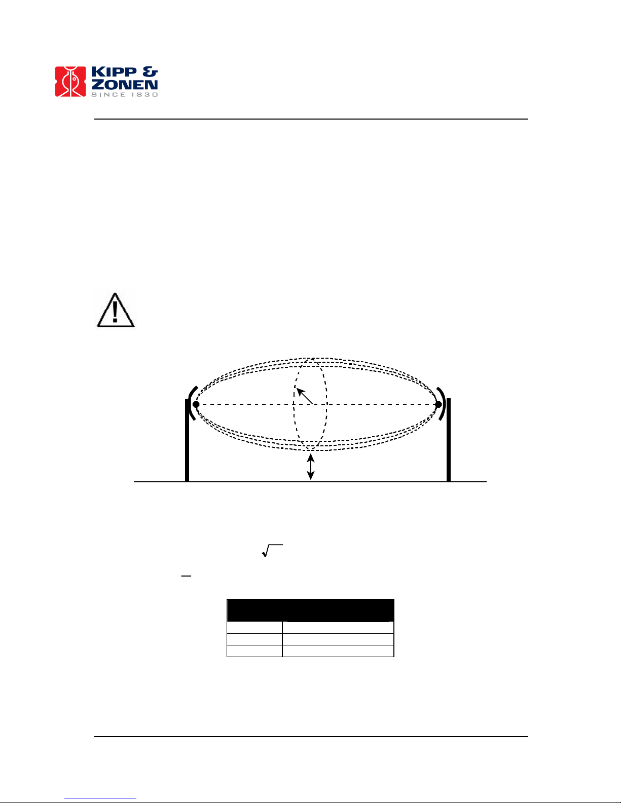
52
• It is NOT recommend placing the antennas near commercial transmitters as their powerful
signal can overwhelm the signal to communication problems! Low power emitters and
receivers may not be a problem.
• Do not mount the antennas near large metal objects. When metallic objects are to close to the
antenna it has the potential to interfere with the way the antenna radiates and may cause
undesirable results.
• The LAS-RET is supplied with 2 high performance antenna cables of 5 m each. Do not extend
the cables as they reduce the performance of the RF link (instead extend the RS-485 cables).
• Avoid rain inside the antenna connectors. Use self-amalgamating tape to waterproof all
connectors.
It is highly recommended to first test the RF link before installing the LAS / XLAS and weather station!
Important: This radio equipment is approved only for mobile and base station transmitting
devices, separation distances of (
1
) 20 centimeters or more for antennas with gains < 6
dBi or (
2
) 2 meters or more for antennas with gains ≥ 6 dBi should be maintained between
the antenna of this device and nearby persons during operation. To ensure compliance,
operation at distances closer than this is not recommended.
Freznel
zone
Figure 35: Shape of the Freznel zone between the antennas of the RF modems. The size of the Freznel
zone is determined by the path length and the frequency of the RF modems. The interference of the
ground with the central diameter of the Freznel zone must be small!
Table 5: Freznel zone diameters ( LF
λ
= , where F = Freznel zone, L = path length [m] and
λ
=
wavelength [m],
f
c
=
λ
, where c = speed of sound [3 × 10⁸ m s-1], f = frequency [Hz])
Distance Diameter Freznel zone
(2.4 GHz RF modems)
300 m 5.4 m
1.6 km 8.4 m
8 km 15.2 m
Page 54

53
APPENDIX 4 – SERIAL PORT CONNECTIONS
Figure 36: Standard RS-232 (DB-9) DCE connector and pin numbering.
1. Computer ↔ COMBILOG
Computer
(DB-9 Female)
COMBILOG
Pin 3 RX (RS-232 Receive)
Pin 2 TX (RS-232 Transmit)
Pin 5 Com (RS-232 Common)
2. Computer ↔ RF Modem (modem in RS-232 configuration)
Computer
(DB-9 Female)
RF Modem
(DB-9 Male)
Pin 1 Pin 1
Pin 2 Pin 2
Pin 3 Pin 3
Pin 4 Pin 4
Pin 5 Pin 5
Pin 6 Pin 6
Pin 7 Pin 7
Pin 8 Pin 8
Pin 9 Pin 9
Use the included standard RS-232 cable that comes with the RF Modems.
3. RF Modem (modem in RS-485 2-wire half duplex configuration) ↔ COMBILOG
RF Modem
(DB-9 Male)
COMBILOG
Pin 2 A (RS-485)
Pin 8 B (RS-485)
Power
RS485
RS232
Page 55

54
Page 56

55
APPENDIX 5 – INSTALLATION FORM
Important: It is highly recommend to fill this form immediately after the installation of the
LAS-system, as most of these parameters are required for the EVATION data processing
software!
Date: …………………… [Year/Month/Day]
Installed by: ……………………
Station name: …………………… (convenient to use in EVATION as working directory)
1. Weather station/sensors
Sensor S/N COMBILOG
Channel
[no]
Height/
depth
[m]
Orientation
[o]
GPS coordinates weather station: ……………………………….. [Latitude,
o
]
……………………………….. [Longitude,
o
]
……………………………….. [Elevation, m]
Height antenna in mast: ……………………………….. [m]
Mean vegetation height around weather station: ……………………………….. [m]
Page 57

56
2. LAS/XLAS
Serial number LAS/XLAS: ……………………
GPS coordinates LAS-Transmitter: …………………… [Latitude,
o
]
…………………… [Longitude,
o
]
…………………… [Height, m] (
10
)
…………………… [Elevation, m] (
11
)
“Current adjust” knob Transmitter: …………………… [-]
Mean vegetation height at LAS-Transmitter site: …………………… [m]
GPS coordinates LAS-Receiver: …………………… [Latitude,
o
]
…………………… [Longitude,
o
]
…………………… [Height, m] (
8
)
…………………… [Elevation, m] (
9
)
Average signal strength Receiver (acc. to analogue meter): …………………… [-]
Short range/Long range knob set to: short / long
Mean signal strength at Receiver (U
DEMOD
): …………………… [mV]
“Path length” Potentiometer setting Receiver (Pot
LAS/XLAS
): …………………… [-]
This corresponds to a distance of: …………………… [m]
(See LAS Instruction Manual section 3.8 for conversion units to meters)
Exact path length (according to a GPS or map): …………………… [m]
Distance LAS-Receiver to Weather station: …………………… [m]
= Path length RF Telemetry link
(according to a GPS or map)
Height antenna at LAS-Receiver site: …………………… [m]
Mean vegetation height at LAS-Receiver site: …………………… [m]
10
Height of LAS above the ground
11
Height of the area above sea level (this information can be obtained from maps)
Page 58

57
3. Effective height LAS / XLAS
The accuracy of the fluxes of sensible heat and evaporation depends strongly on the mean height of
the LAS above the surface. In case the area is completely flat the average beam height can be easily
derived from the Transmitter height and the Receiver height. In case the area is very complex (such
as shown in Figure 37) it becomes more difficult to determine the effective height of the LAS / XLAS.
The EVATION software has a special tool that helps the user to determine the effective height
(“Effective height calculator”). The “effective height calculator” needs the following input data:
transmitter installation height, receiver installation height, the elevation of the transmitter and receiver
site, and the elevation plus position of a number of points along the optical path of the LAS (i.e.
EVATION needs a cross section of the LAS setup over the area). By entering this information in the
“Effective height calculator” the software gives you the effective height of the LAS, which finally will be
used in the actual data processing to fluxes. An example is shown in Table 6 and Figure 37. You can
use the table below for collecting a number of points to determine the effective height of your LAS
setup.
Distance to
reference
[m]
Elevation
[m]
1
2
3
4
5
6
7
8
9
10
11
12
13
14
15
16
17
18
19
20
21
22
23
24
25
26
Page 59

58
Table 6: Example of the cross section of a LAS set-up. These data points are used in EVATION to
determine the effective height of the LAS (see Figure 37).
Elevation in
respect to
reference1
[m]
Distance from
reference
[m]
Height of LAS in
respect to surface
[m]
Transmitter site
(here taken as
reference) = TX
0 0 50
2
Int. point 1 0 500
Int. point 2 3 750
Int. point 3 7.5 1000
Int. point 4 7.5 2300
Int. point 5 20 3000
Int. point 6 20 3500
Int. point 7 18 3700
Int. point 8 18 4000
Int. point 9 25 4500
Receiver site =
RX
36 47003 304
1
Can be negative values with respect to the reference point
2
Installation height transmitter unit
3
Path length LAS / XLAS
4
Installation height receiver unit
1
2
3
4
5
6
7
8
9
Beam
’Reference’
Receiver
Transmitter
Figure 37: Determination of effective LAS height based the LAS set-up and cross section of the area.
Page 60

59
APPENDIX 6 – INSPECTION PROCEDURE
Every time one visits the weather station and the LAS (preferably at a 2 week interval) it is
recommended to follow the inspection procedure given here:
1. Check the power supply of the weather station (Solar panel and battery)
Check if the green LED labelled “RUN” of the COMBILOG data logger is activated. If so the
display of the COMBILOG should show the actual date and time and the real time
measurements of all sensors.
In case the COMBILOG is NOT responding check the power supply. First, check the LED
information of the solar controller (see error messages (left LED 1, Table 7) and state of
charge battery (right LED 2, Table 8)).
Table 7: Status and color left LED 1 of Solar Controller (error messages).
LED 1 Status Load Action
Green
flashing
All OK - No reset
Red-green
flashing
Load current is too high Disconnected Switch of or disconnected users,
remove error, reconnect users
Red-yellow
flashing
Module current is too
high
Disconnected Automatically, when over current does
no longer exist
Constant red Controller is over heated
(> 85
o
C)
Disconnected Automatically, when temperature has
decreased
Yellow
flashing
Battery voltage is too
high (> 15 VDC)
Disconnected Automatically, when voltage has fallen
Red flashing Battery voltage is too
low (< 10.5 VDC)
Disconnected Automatically, when voltage is
increased again
Table 8: Status and color of right LED 2 of Solar Controller (SOC).
LED 2 Level State Of Charge
battery (SOC)
Comments
Green 1 100 % (battery full) 2 90 % 3 80% 4 70 % 5 60 % Yellow 6 50 % 7 40 % Pre-Warning: load is about to be disconnected (LED 2 is
fast flashing)
8 30 % Load is disconnected (SOC < 30 %)
Load will be connected again when SOC = 50%)
9 20% Red 10 0% (battery empty) -
In case the solar controller is operational, the battery is in good condition (SOC > 50 %) and
the load is connected, but the data logger and sensors are not functioning check the fuse
located at the overvoltage protection unit (see Figure 38, location 1).
When the solar controller is not operational (all LED’s are switched off) check the fuses
located in front of the solar controller and the fuse located at the plus pole of the battery (see
Figure 38, location 2 and 3).
Page 61

60
Check the wiring both inside and outside the enclosure when fuses are broken. Finally,
replace the fuses by new ones.
Measureme nt
signal
Power terminal
with interna l
fuse
Power/sig nal
cables
Over voltag e
protection
12 VDC Power
RS485
Antenna c able
RF modem
Solar pane l
Solar controller
with internal fuse
12 VDC Battery
plus externa l fuse
Adapter and
lightning arrestor
To PC
RS232
Steel e nclosur e weathe r station
‘Load’ (1 2 VDC)
Pressure sensor
Earthing
Sensors
1
2
3
Figure 38: Location of fuses in enclosure of LAS-RET (1: Power terminal; 2: Solar
controler; 3: Battery).
Measur ement
signal
Power terminal
with internal
fuse
Power/signal
cables
Over voltag e
protection
12 VDC Power
To PC
RS232
Steel e nclosure
12 VDC power
Pressu re sensor
Earthing
LAS- Receiver + Sensors
1
Figure 39: Location of fuses in enclosure of LAS-BET (1: Power terminal).
2. Check data logger date and time
To change data/time see APPENDIX 7 – SETTING DATE / TIME COMBILOG for instructions
or the COMBILOG instruction manual.
3. Check sensor output
When all sensors of the weather station are operational the red LED “ERR” of the COMBILOG
is switched OFF. In case one of sensors of the weather station is malfunctioning the red LED
Page 62

61
is ON. The output of each channel can be visualized on the display of the COMBILOG using
the “SELECT” press/rotary knob on the data logger. Table 4 shows a typical range for each
sensor of the LAS-system. Check if the output of the sensor lies within the given range.
If one of the station’s sensors is defect or malfunctioning the value –9999 is shown on the
display. This applies for every sensor except for the wind speed sensor. In case this sensor is
malfunctioning 0 m s
-1
is displayed. Since 0 m s-1 can occur the LED “ERR” will not respond.
Therefore, check the wind speed on the display and verify this by looking at the rotations of
the sensor itself. If one of the LAS channels shows –9999 check the LAS (see step 8). If the
LAS channels show ‘no answer’ check the RF telemetry link (see step 4).
Combilog 1020+
U 3.xx
Dat e: dd. mm.yy
Time: hh.mm. ss
LOG: 0 253k b
free: 2 7d
PCMCIA: 1904kb
free: 100d
Chan 1
xx [units]
Chan x
xx [units]
Figure 40: Main menu of COMBILOG, includes the actual sensor output of all sensors (see Chan.
1 to Chan. ×). Description symbols:
3 …. Turn knob clockwise
4 …. Turn knob counter clockwise
Note: For LAS-RET customers who are using the RF telemetry link: the LED “ERR” does not
apply to the LAS / XLAS! Always check the LAS / XLAS signals manually by inspecting the
demod and C
n
2
values on the display (or on site).
4. Check the RF telemetry link and RF modems
Check if the RF modem is operational by looking at the LED indicators at the front side of the
modem (Table 9).
Table 9: Status and LED indicators RF modem.
LED’s Good radio
communication
Failing radio
communication
RF modem off
Yellow (serial data out) Flashing Off Off
Green (serial data in) Flashing Off Off
Red (power/TX
indicator)
On/Flashing On Off
Page 63

62
The RF telemetry link can also be verified by looking at the LAS / XLAS channels on the
display of the COMBILOG. If the LAS channels say ‘no answer’ the RF link is not working. If
this is case check:
• The connectors and antenna cables (also at LAS receiver site). Verify that all connectors
have no water leakages (if necessary use ‘self-amalgamating’ tape to make the
connectors waterproof) and check the condition of the antenna cables (damages).
• Check the condition and orientation of the antennas. Note that the antennas are
directional antennas, which means that a slight miss-alignment of the antenna can
lead to communication failure!
• Intensive rainfall, fog or high objects (trees, in particularly when the leaves are wet),
commercial communication towers can also disturb the communication link.
• Check the power source of the RF-modem. No power means no RF-communication. In
necessary replace broken fuses (and solve short-circuit problems) (see Figure 38).
5. Clean sensors, check signal/power cables and connectors
Check the physical condition of all sensors to prevent malfunctioning (radiation sensor, wind
direction, wind speed, air temperature, relative humidity). If necessary, clean sensors and
remove any dirt (e.g. dust, spider webs and droppings). Check the condition of all cables and
wires (also inside the stainless steel housing), including the various connections (over voltage
protection and data logger. Finally check the leveling of the radiation sensor and the mast (see
next step).
6. Check the condition of the tower, guys, spanner and anchoring
Important: The wire tension has to be moderate and equal. By no means bending forces are
allowed to be applied to the mast!
Important: It is very important to check the anchoring for correct and tight position,
frequently. Especially after high wind speeds occurred. If the soil seems not to be tight
enough to keep the loads, the anchoring has to be replaced by concrete foundations. If
the load lengthens the wires, their length has to be readjusted. The wire condition has to
be checked frequently. Damaged wires have to be replaced at once!
7. Download the data from the COMBILOG: a) replace the PCMCIA Flash Card b) connect a
computer to the RS-232 interface of the COMBILOG.
a) For replacing the PCMCIA Flash Card proceed as follows:
• Remove the ‘full’ PCMCIA card from the COMBILOG
• Insert the new PCMCIA card in the COMBILOG
When the display shows: “FLASH card not empty”
• Rotate the press/rotary knob on the data logger, “FLASH card: Append data?” or
“FLASH card: Delete Card?” will appear. Select “FLASH Card: Delete card?” and
press the knob briefly to confirm, the FLASH card will be deleted and new data (plus
header) will be stored in the empty FLASH card (this will take about 16 seconds).
When nothing happens:
• First, enable the press/rotary knob of the data logger.
Page 64

63
For safety reasons the press/rotary knob of the data logger is disabled (automatically done by
the COMBILOG data logger), meaning that part of the configuration menu cannot be accessed.
In order to enable this knob, go to “COMBILOG 1020+” of the main menu by rotating the
press/rotary knob. Press the knob briefly. The configuration menu will be accessed. Rotate the
knob until “Input disabled” appears on the display. Again press the knob briefly. Rotate the
knob again until “Input < enable >” appears and press the knob briefly. The knob is now
enabled to modify all settings of the data logger manually. Go back to the main menu, by
pressing the knob for about 1 second, you will return to the main menu (“COMBILOG 1020+”
appears). Note that the knob will be disabled again after 30 seconds if no operations are
performed on the knob.
• Second, delete the FLASH card.
Go to “PCMCIA: ……. kb; free: ……. d” of the main menu by rotating the press/rotary knob.
Press the knob briefly. On the display appears “Flash Card delete?”. Press the knob briefly to
confirm. The FLASH card will be deleted and new data (plus header) will be stored in the empty
FLASH card (this will take about 16 seconds).
• To read the ‘full’ PCMCIA Flash using a computer. Go to 4.3.2 Reading PCMCIA
Flash Memory Cards.
b) Downloading data via RS-232 interface:
When using PCMCIA Flash Cards this option CANNOT be used!
• Connect the PC to the RS-232 interface of the COMBILOG.
• Start the COMBILOG support software.
• Scan for available COMBILOG data loggers.
• Click on Utilities → Read Logger and follow instructions.
8. Check the LAS / XLAS
First check the output of the LAS signals (i.e. C
n
2
signal (= Cn2 or PUCn21000) and signal
strength (= Demod or U
DEMOD
) on the display of the COMBILOG (see step 3) at the weather
station.
a) The display shows ‘no answer’:
This message indicates that either the power supply of the RF modem is broken down or the
problem lies in the RF communication link. Check the following:
• The connectors and antenna cables (at both sites). Verify that all connectors have no
water leakages (if necessary use ‘self-amalgamating’ tape to make the connectors
waterproof) and the status of the cables.
• Check the condition, direction and orientation of the antennas. Note that the
antennas are directional antennas, which means that a slight miss-alignment of
the antenna leads to RF communication failure!
• Intensive rainfall, fog or high objects (trees, in particularly when the leaves are wet),
commercial communication towers can also disturb the communication link. Verify
whether the RF links is operational during clear sky conditions.
• Check the power source of the RF-modem. No power means no RF-communication.
In necessary replace broken fuses (and solve short-circuit problems) (see Figure 38).
b) The display shows –9999:
This means that the power supply of the RF modem is working fine. The problem is likely
related to power source or signal strength problems of the LAS / XLAS. Proceed as follows:
Page 65

64
• Check the power source of the transmitter, the status of the transmitter unit (see
“power” LED) and the current through the LED (via current adjust knob and BNC
socket). For further information see the LAS instruction manual.
• Check the power source of the receiver and the status of the receiver unit (see
“power” LED). Perform a calibration check of the electronics. For further information
see the LAS instruction manual.
• Check the windows of both the transmitter and receiver unit. Dust, water droplets and
icing on the windows lead to signal attenuation. Regularly clean the windows and if
necessary turn the window heater on.
• Check the transmitter and receiver units for water leakage and internal condensation
on the lenses and windows, as this can also lead to signal attenuation (and even
corrosions of the electronics!). Although the housing of the both the transmitter and
receiver unit are sealed with O-rings (plus silicagel packages and RH-indicator),
improper closure of the back panel and a loose cable plug can lead to water leakage
and as a result to internal condensation problems. If necessary replace the silicagel
packages by new ones (see RH-indicator on rear window). See LAS manual for
further information.
• The alignment of the LAS (for further instructions see section 3.7 of the LAS / XLAS
instruction manual). An unstable mounting construction for the LAS can regularly lead
to a misalignment of the LAS.
c) The display shows realistic values:
This indicates that the LAS is working fine. Check if the signal strength (= Demod or U
demod
) is
stable and similar to the value when the LAS was installed and optically aligned. In theory the
signal strength should be stable. Except during conditions of rain, fog, or low visibility the
signal can drop to zero. In case the visibility conditions are good but the signal strength has
dropped significantly, check the following:
• Check the windows of both the transmitter and receiver unit. Dust, water droplets and
icing on the windows lead to signal attenuation. Regularly clean the windows and if
necessary switch the window heater on.
• Check the transmitter and receiver units for water leakage and internal condensation
on the lenses and windows, as this can also lead to signal attenuation (and even
corrosions of the electronics). Although the housing of the both the transmitter and
receiver unit are sealed with O-rings (plus silicagel packages and RH-indicator),
improper closure of the back panel and a loose cable plug can lead to water leakage
and as a result to internal condensation. If necessary replace the silicagel packages
by new ones (see RH-indicator on rear window). See LAS manual for further
information.
• The alignment of the LAS (for further instructions see section 3.7 of the LAS / XLAS
instruction manual). An unstable mounting construction for the LAS can regularly lead
to a misalignment of the LAS.
Page 66

65
APPENDIX 7 – SETTING DATE / TIME COMBILOG
There are two ways to change the date/time of the COMBILOG data logger. First, by using the
COMBLOG support software. Second, manually using the press/rotary knob on the COMBILOG data
logger.
1. Automatically using the COMBILOG support software
Figure 41: Synchronize date/time of the COMBILOG data logger using the PC date/time.
First check the PC date and time before synchronizing the data logger data and time.
2. Manually using press/rotary knob
The press/rotary knob on the data logger allows the user to modify the settings of the data logger
manually. By turning/pressing the knob the several menu items can be selected in order to modify the
COMBILOG settings, such data/time, scan interval etc.
The following symbols are used for the operations:
3 …. Turn knob clockwise
4 …. Turn knob counter clockwise
3 …. Press knob briefly (confirmation)
× …. Press knob for approximately 1-second minimum (abortion)
The instructions below plus details are also found in the COMBILOG instruction manual.
Page 67

66
Combilog 1020+
U 3.xx
Date: dd.mm.yy
Time: hh.mm. ss
LOG: 0 253kb
free: 2 7d
PCMCIA: 1904kb
free: 100d
Chan 1
xx [units]
Chan x
xx [units]
Servi ce mode
normal
Weather station
Adr. : 1 19 200N
Auto. off: OFF
LEDs: ON
Scan Rate: 4s
Averaging: 10m
Display Contrast
adjust?
Inpu t
disable
Combilog 1020+
U 3.xx
Figure 42: Main menu (left) and Configuration menu (right) of COMBILOG data logger.
Step 1: Enable the press/rotary knob of the data logger
For safety reasons the press/rotary knob of the dat alogger is disabled (automatically done by the
COMBILOG data logger), meaning that part of the configuration menu cannot be accessed. In order to
enable this knob, go to “COMBILOG 1020+” of the main menu by rotating the press/rotary knob. Press
the knob briefly. The configuration menu will be accessed. Rotate the knob until “Input disabled”
appears on the display (see Figure 42). Again press the knob briefly. Rotate the knob again until
“Input < enable >” appears and press the knob briefly. The knob is now enabled to modify all settings
of the data logger manually. Go back to the main menu, by pressing the knob for about 1 second, you
will return to the main menu (“COMBILOG 1020+” appears).
Note that the knob will be disabled again after 30 seconds if no operations are performed on the knob.
Inpu t
< disable >
Inpu t
< enable >
Inpu t
disable
Figure 43: Lock/Unlock of the press/rotary knob of the COMBILOG data logger.
Page 68

67
Step 2: Setting of date / time
Go to “Date: YY.MM.DD / Time: HH.MM.SS” in the main menu and press the knob briefly. Select
between “Set Date” and “Set Time” (rotate knob). By pressing the knob briefly the date/time can be
changed. Once the date/time is correct, press the knob briefly to confirm.
Set Da te?
Set Ti me?
Auto. off: OFF
LEDs: ON
Scan Rate: 4s
Aver aging: 10m
Date: dd.mm.yy
Time: hh.mm. ss
Figure 44: Setting of date and time of COMBILOG data logger.
Page 69

68
Page 70

69
APPENDIX 8 – FORMAT PCMCIA FLASH MEMORY CARDS
To format a Flash Memory Card for COMBILOG data loggers follow the following steps:
1. Insert the PCMCIA flash memory card into your card reader.
2. Start CardWare software (PCCard Control).
3. Go to taskbar Cards and click on Open MCView Main Window.
Figure 45: The memory Cards Viewer MCView is a control utility that enables special memory card
operations to format Flash Memory Cards for usage in the COMBILOG.
4. Select Erase Card from the Raw Access menu.
5. After the card has been erased, write the predefined image data to the card using the Write
Raw Data function (Go to Raw Access menu and select Write Raw Data…). The image files
are available on the installation CD (sub directory image files) and are named accordingly to
the size of the card (i.e. select the 2 Mb).
6. After writing the image, the file “00000001.FIL” is available on the file list. This file should be
renamed to “COMBILOG.LOG”, before the card is used with the COMBILOG data logger.
(Click the right mouse button to the file name and choose Rename).
Important: The function Card Stop (see Figure 45) or Eject Card (via Open MCView, see
Figure 46) should be used to eject/unplug the card before removing the card from the
device/computer!
Figure 46: Eject/unplug the PCMCIA flash card from your computer via MCView window.
Page 71

70
APPENDIX 9 – CONNECTION PLAN LAS-BET & LAS-RET
Figure 47: Connection plan LAS-BET system.
Page 72

71
Page 73

72
Figure 48: Connection plan weather station LAS-RET system.
Page 74

73
Figure 49: Connection plan scintillometer LAS-RET system.
Page 75

0353 200 1001
HE AD OFFICE
Kipp & Zonen B.V.
Delftechpark 36, 2628 XH Delft
P.O. Box 507, 2600 AM Delft
The Netherlands
T: +31 (0) 15 2755 210
F: +31 (0) 15 2620 351
info@kippzonen.com
Kipp & Zonen France S.A.R.L .
7 Avenue Clément Ader
ZA Ponroy - Bâtiment M
94420 Le Plessis Trévise
France
T: +33 (0) 1 49 62 41 04
F: +33 (0) 1 49 62 41 02
kipp.france@kippzonen.com
Kipp & Zonen Asia Pacifi c Pte. Ltd.
81 Clemenceau Avenue
#04-15/16 UE Square
Singapore 239917
T: +65 (0) 6735 5033
F: +65 (0) 6735 8019
kipp.singapore@kippzonen.com
Kipp & Zonen U.K. Ltd.
P.O. Box 819,
Lincoln, Lincolnshire
LN6 OWY
Un
ited Kingdom
T: +44 (0) 1522 695 403
F: +44 (0) 1522 696 598
kipp.uk@kippzonen.com
Kipp & Zonen USA Inc.
125 Wilbur Place
Bohemia
NY 11716
United States of America
T: +1 (0) 631 589 2065
F: +1 (0) 631 589 2068
kipp.usa@kippzonen.com
SA LES OFFI CES
Go to www.kippzonen.com for your local distributor or contact your local sales office
Our customer support remains at your disposal for any maintenance or repair, calibration,
supplies and spares.
Für Servicearbeiten und Kalibrierung, Verbrauchsmaterial und Ersatzteile steht Ihnen unsere
Customer Support Abteilung zur Verfügung.
Notre service 'Support Clientèle' reste à votre entière disposition pour tout problème de
maintenance, réparation ou d'étalonnage ainsi que pour les accessoires et pièces de rechange.
Nuestro apoyo del cliente se queda a su disposición para cualquier mantenimiento o la
reparación, la calibración, los suministros y reserva.
Passion for Precision
 Loading...