

Page 1
COMBILOG 1022
Data Logger
Hardware Manual Version 1.04
Page 2

Issue: 22.01.2010
Technical data are subject to change!
Hardware Manual COMBILOG 1022
2
Page 3

Copyright 1995-2010, Theodor Friedrichs & CO
(Germany).
Copyrights: Operating instructions, manuals and software are
subject of copyright. Copying, duplication, translation, conversion into any electronic medium or any machine readable form,
as a whole or in parts, is not permitted, with the exception of
making a back-up copy of the software for saving purposes, insofar as this is technically feasible and is recommended by our
company. Contraventions will lead to compensation.
Limitation of Liability: No liability is assumed by Theodor
Friedrichs for damages and/or injury resulting from use of
equipment supplied by this company. In no event will Theodor
Friedrichs be liable for indirect or consequential damages whatsoever resulting from loss of use, data or profits arising out of
connection with the use of performance of Theodor Friedrichs
products. Theodor Friedrichs products are not designed, intended, or authorized for use as components and medical systems, or other applications indeed to support or sustain life, or
for any other application in which the failure of the Theodor
Friedrichs product(s) could create a situation where personal
injury or death may occur.
Any claims against Theodor Friedrichs in connection with the
hardware and software products described in this manual can
exclusively be based on the guarantee regulations. Any further
claims are excluded, in particular Theodor Friedrichs does not
give any guarantee as to the correctness of the contents of this
manual. Changes are subject to alteration and can be executed
any time without advanced notice.
Trade Marks: Without going into details, we want to point out
the usage of indications and entered trade marks, in particular
the indications and trade marks of Microsoft Corporation, In-
ternational Business Machines Corporation and Intel Corporation.
________________________________________
Hardware Manual COMBILOG 1022
3
Page 4

Hardware Manual COMBILOG 1022
4
Page 5

CHAPT ER S UR VE Y
Page
1 GENERAL PRELIMINARY REMARKS...............10
2 SYSTEM DESCRIPTION........................................12
3 INSTALLATION.......................................................19
4 SIGNAL PROCESSING..........................................28
5 FUNCTIONAL DESCRIPTION..............................34
6 DISPLAY / MENU OPERATION...........................60
7 DATA STORAGE.....................................................74
8 MASTER FUNCTION..............................................81
9 INITIATION AND TEST..........................................84
10 STRUCTURE OF THE BUS TOPOLOGY...........86
11 COMMUNICATION..................................................99
12 WEBSERVER.........................................................144
13 SPECIFICATIONS.................................................147
14 SIMPLIFIED DRAWINGS....................................154
Hardware Manual COMBILOG 1022
5
Page 6

TABLE O F CO NT EN TS
Page
1 GENERAL PRELIMINARY REMARKS...............10
1.1 About this Manual....................................................................10
1.2 Important Notice......................................................................10
1.3 Contact for Inquiries................................................................11
2 SYSTEM DESCRIPTION........................................12
2.1 System Overview.....................................................................12
2.2 Range of Application...............................................................13
2.3 Features..................................................................................15
2.4 Configuration Software............................................................17
3 INSTALLATION.......................................................19
3.1 Mounting / Fixing.....................................................................19
3.2 Protective System....................................................................19
3.3 Ambient Temperature..............................................................20
3.4 Front panel / Pin Assignment..................................................20
3.5 Connection .............................................................................22
3.6 Power Supply..........................................................................23
3.7 Bus Connection.......................................................................25
3.8 Sensor Connection..................................................................26
3.9 Several Sensors at one Data Logger......................................27
3.10 Module Jack............................................................................27
4 SIGNAL PROCESSING..........................................28
4.1 Analogue Inputs.......................................................................28
4.2 Digital Inputs/Outputs..............................................................28
4.3 Power Switch...........................................................................29
4.4 Internal Reference Voltage, Offset- and Drift Correction.........30
4.5 Internal Processing..................................................................31
4.6 Scan Rate and Power Consumption.......................................32
4.7 Signal Processing....................................................................33
Hardware Manual COMBILOG 1022
6
Page 7

5 FUNCTIONAL DESCRIPTION..............................34
5.1 Analogue Input Channel..........................................................35
5.1.1 Voltage Measurement.............................................................36
5.1.2 Current Measurement..............................................................38
5.1.3 Resistance Measurement........................................................40
5.2 Digital Input Channel...............................................................45
5.2.1 Digital Status Recording..........................................................46
5.2.2 Frequency Measurement.........................................................47
5.2.3 Progressive Counter................................................................49
5.3 Digital Output Channel............................................................50
5.3.1 Digital Status Output:...............................................................50
5.4 Arithmetic Channel..................................................................52
5.5 Setpoint Channel.....................................................................58
5.6 Alarm Channel.........................................................................58
5.7 Serial Channel.........................................................................58
5.8 Threshold Values.....................................................................58
5.9 Error Handling.........................................................................59
6 DISPLAY / MENU OPERATION...........................60
6.1 Display and Operation.............................................................60
6.2 Menu Items..............................................................................60
6.3 SD-Card...................................................................................72
6.3.1 Remove Card..........................................................................72
6.3.2 Firmware Update.....................................................................73
7 DATA STORAGE.....................................................74
7.1 General Remarks to Data Storage..........................................74
7.2 Modes of Data Storage............................................................74
7.3 Storage Medium......................................................................75
7.4 Internal Data Storage..............................................................76
7.5 External Data Storage with SD Card.......................................78
8 MASTER FUNCTION..............................................81
8.1 Master Function.......................................................................81
Hardware Manual COMBILOG 1022
7
Page 8

9 INITIATION AND TEST..........................................84
9.1 Before Connecting the Device.................................................84
9.2 After Connecting the Device....................................................84
9.3 Configuration of the Data Logger............................................84
10 STRUCTURE OF THE BUS TOPOLOGY...........86
10.1 Bus Interface...........................................................................87
10.2 Bus Structure...........................................................................88
10.3 Transmission Speed and Line Length.....................................89
10.4 Bus Cable................................................................................90
10.5 Bus Plug..................................................................................91
10.6 Bus Termination......................................................................92
10.7 Shielding..................................................................................94
10.8 PC Bus Connection.................................................................95
10.9 Potential Equalization..............................................................96
10.10 Adjustment of Address and Baud Rate...................................96
11 COMMUNICATION..................................................99
11.1 Bus Interface...........................................................................99
11.2 Bus Protocol............................................................................99
11.3 Data Format...........................................................................100
11.4 Output Format.......................................................................101
11.5 Transmission Sequence........................................................104
11.6 ASCII protocol.......................................................................106
11.6.1 Telegram Format for the ASCII Protocol...............................106
11.6.2 Instruction Set in the ASCII-Protocol.....................................109
11.7 PROFIBUS protocol..............................................................116
11.7.1 Telegram Format for the Profibus Protocol...........................116
11.7.2 Instruction Set in the PROFIBUS-Protocol............................120
11.8 MODBUS protocol.................................................................128
11.8.1 Telegram Format for the MODBUS-RTU Protocol................128
11.8.2 Instruction Set in MODBUS-RTU Protocol............................129
11.9 Sample Program....................................................................140
11.10 Autocall Function...................................................................141
Hardware Manual COMBILOG 1022
8
Page 9

11.11 Modem Connection...............................................................143
12 WEBSERVER.........................................................144
12.1 General..................................................................................144
12.2 System Info............................................................................144
12.3 System Log............................................................................144
12.4 Data View..............................................................................144
12.5 Data Logger...........................................................................145
12.6 Configuration / Login.............................................................145
12.7 Single Channel Configuration................................................145
12.8 Power Switch.........................................................................145
12.9 Serial Channel.......................................................................145
12.10 Logger Configuration.............................................................146
12.11 Password...............................................................................146
12.12 Protocol.................................................................................146
12.13 Logout....................................................................................146
13 SPECIFICATIONS.................................................147
13.1 Power Supply........................................................................147
13.2 Signal Inputs/Outputs............................................................147
13.3 Signal Processing..................................................................147
13.4 Analogue Inputs (8 per Module)............................................148
13.5 Digital Inputs/Outputs (6 per Module)....................................149
13.6 Interfaces...............................................................................149
13.7 Operating Conditions.............................................................151
13.8 Electromagnetic Compatibility...............................................151
13.9 Shell.......................................................................................152
13.10 Circuit....................................................................................152
13.11 Accessories / Notice for Orders.............................................152
14 SIMPLIFIED DRAWINGS....................................154
14.1 Front View.............................................................................154
Hardware Manual COMBILOG 1022
9
Page 10

1 GENERAL PRELIMINARY REMARKS
1.1 About this Manual
The manual contains all important information concerning the
function, installation and initiation of the data logger
COMBILOG 1022.
The description of the configuration software for the
COMBILOG-System is available as Online-Help within the configuration software COMBILOG.EXE.
1.2 Important Notice
Make sure to use the data logger COMBILOG 1022 exclusively
in accordance with the notices, technical data and operating
conditions mentioned in this manual. In case of inexpert handling or wrong application possible disturbances, measuring errors, effects on or from other appliances and facilities as well
as possible endangering of human lives or tangible assets cannot be excluded!
Therefore if you have not yet operated the data logger
COMBILOG 1022, you should first of all study this manual
thoroughly. While initiating or operating the appliance or in
case service is required always observe the notices given in
this manual.
Please note further that there are other special regulations to
be observed in case of application in potentially explosive surroundings (EExe, EExi, ...). These, however are not subject of
Hardware Manual COMBILOG 1022
10
Page 11

this manual, which only explains the general use of the data
logger COMBILOG 1022.
1.3 Contact for Inquiries
In case of inquiries concerning the data logger
COMBILOG 1022 please contact your local distributor or
directly Theodor Friedrichs & Co. GmbH.
Hardware Manual COMBILOG 1022
11
Page 12

2 SYSTEM DESCRIPTION
2.1 System Overview
The COMBILOG 1022 is a data logger with compact
design, combined with integrated LC-display and memory slot
suitable for SD cards.
This data logger was developed for meteorological, hydrological and environmental measuring systems, but it is equally suitable for countless further applications in industrial production.
The COMBILOG 1022 features high performance, compact
design (SMD components), low power consumption and moderate price.
The data logger is equipped with 8 analogue and 6 digital
measuring channels; further channels for numeric calculation
may be configured. Four serial interfaces RS232, RS485, USB
and Ethernet are built-in, featuring communication via ASCII,
PROFIBUS or MODBUS. Data storage is achieved by internal
Flash or SD memory card, optionally.
„SELECT“ switch and 4-line LCD on the front panel allow to
enter or modify a number of different modes and functions,
such as scan rate and averaging time, as well as offset or gain.
The COMBILOG 1022 can easily be mounted on a 35 mm
standard rail using its „snap-in“ clamp and is therefore suitable
for control cabinet installation or similar.
Thanks to its low power consumption, battery supplied systems
are possible, whereby the use of a solar panel enables any extension of measuring period.
Hardware Manual COMBILOG 1022
12
Page 13

For applications like outdoor use there is a version with stainless steel housing available, as well as various other accessories.
Configuring of the data logger is accomplished by means of an
easy to handle WINDOWSTM 98 / ME / NT / 2000 / XP software.
2.2 Range of Application
As described under (2.1), the most varying measurement tasks
can easily be accomplished by means of the COMBILOG 1022.
Some typical applications are e.g. measurement of temperature via resistance thermometers (Pt100), operation with combined sensors with current- or voltage output (e.g. wind speed
measurement with DC generator) or position measurement and
weight measurement by displacement transducers and force
transducers. With these applications the data logger
COMBILOG 1022 supports measuring methods with 2-, 3- and
4-wire technique. The signal processing required in accordance
with the sensors used, such as gain, linearisation, offset correction etc. can be adjusted individually by software. An external amplifier is not required.
The digital signal inputs can be used, for example, to connect
switches, initiators, digit emitters and oscillators. Thus status
indications can be collected and tasks like e.g. position measurements, displacement measurements, angular measurements, frequency measurements and timings can be carried
out. Furthermore special 8-bit-Graycode-transmitters can be
connected.
Special calculations of measured values are possible by arithmetic channels. In case the 8 analogue and 6 digital inputs are
not sufficient, other modules can be connected to the data
Hardware Manual COMBILOG 1022
13
Page 14

logger via the RS485 bus. In this case the COMBILOG is used
as a bus master to read the measured values from the slave
modules.
All data can be transmitted via the integrated RS485 communication interface to a subsequent control (PLC) or to a computer (PC). Up to 127 modules can be connected with the twowire line over distances of several km. At the same time the
communication interface features programming and configuring
the individual application from a PC.
If the data logger COMBILOG 1022 is not integrated in a bus,
an additional RS232-interface is available for the user. This interface allows only a point-to-point connection up to max. 20 m
(65 feet), but all functions of the RS485-interface remain available.
Furthermore the data logger can send messages in case of
user definable conditions automatically via modem or SMS.
A configuration program is included (requires Microsoft
WINDOWS 98,ME,NT,2000, XP).
Hardware Manual COMBILOG 1022
14
Page 15

2.3 Features
Function:
Measurement inputs for all common types of sensors for I,
U and R.
Several different sensors can be connected simultan-
eously
Measured values monitored by programmable thresholds
Detection of sensor errors
Detection of communication errors
Programmable error handling
Calculation of average values, minima, maxima, standard
deviation and other arithmetic functions
7 MByte Flash internal data storage, extendible with ex-
ternal SD card
Inputs and outputs:
8 analogue inputs (for 2-, 3- and 4-wire connection)
6 digital inputs/outputs (I/O ports), configurable
Power supply:
Power supply: +10 ... +30 VDC
All connections protected against excess voltage, excess
current and reverse polarity
Battery operation is possible due to low power consump-
tion
Display and operation:
LED-status indication for digital inputs/outputs
LED-status indication for malfunction and operation (ERR /
RUN)
Hardware Manual COMBILOG 1022
15
Page 16

LED-status indication for the ethernet interface
LC-display (4 x 16 characters) and push-/turn knob for op-
eration
Measured value processing:
Linearisation, scaling and conversion into physical units
Option to adjust, modify or reset the processing paramet-
ers individually
Master function to retrieve data from external modules
Programmable averaging
Automatic message transmission via modem or SMS
Non-volatile storage for program, parameters and data
Configuration:
Configurable with PC-software under
WINDOWS™ 98 / ME / NT / 2000 / XP
Menu-guided sensor selection in plain text
Free configuration of up to 32 channels
Data base for the most common sensors
Definition of user-specific sensors
Setting of type and principle of measurement
Display of pin assignment
Input of linearisation
Alarm settings
Programmable error handling
Arithmetic combination of sensor channels
Configurable measuring rate and averaging interval
Configuration on file (offline-operation)
Configuration via bus (online-operation)
Programming:
Allocation of address and baud rate via bus
Password to save the configuration and the data memory
Synchronizing of date and time with the host PC
Hardware Manual COMBILOG 1022
16
Page 17

Communication:
Integrated RS 485, RS 232, USB and Ethernet communic-
ation interface
Autonomous function independent of subsequent systems
Definition of the transmission protocol (ASCII and
PROFIBUS or MODBUS)
Definition of the telegram format (baudrate and parity)
Definition of the output format
(field length / decimals / unit)
Simple instruction set
Shell:
Compact structural shape
Attractive design
Fast mounting
Snap-on mounting on DIN rail 35 mm / 1.4 inch
Protection IP20
Plug-in screwed terminals
Module jack, ground connection
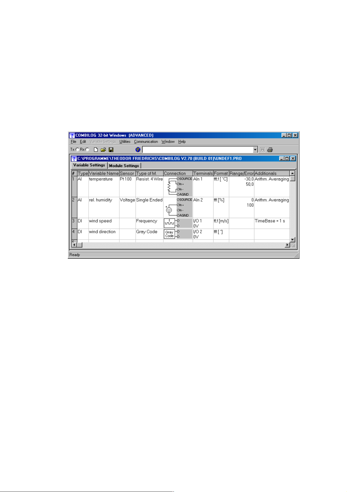
2.4 Configuration Software
The COMBILOG 1022 is delivered with a configuration software for MS WINDOWS 98/ME/NT/2000/XP. This software allows the individual configuration of the data logger.
Measuring channels are defined as variables in a variable
table.
Predefined sensors can be selected from the integrated database. The linearisation of the sensor signals will be performed
automatically. Additional sensors can be defined.
Additional parameters like scan rate, averaging interval, data
recording, error handling, automatic message generation, master function etc. are configurable. A password enables protection of the configuration and the stored data. Instantaneous
measured values can be watched directly.
Hardware Manual COMBILOG 1022
17
Page 18
In case a software update for the data logger is necessary, the
configuration program provides a download function, that
sends the new program to the logger.
Communication is supported via standard interface (RS232),
telephone or GSM modem or TCP/IP protocol.
Example for a configuration:
Hardware Manual COMBILOG 1022
18
Page 19

3 INSTALLATION
3.1 Mounting / Fixing
The data logger COMBILOG 1022 has a snap-on mounting for
installation on standard profile rails 35 mm (1.4 inch) according
to DIN EN 50022.
Installation on the DIN rail is performed by means of the four
straps on the rear side of the data logger. First push the two
straps on the bottom behind the notch of the DIN rail and then
press the data logger on the DIN rail until the two straps on the
top snap in.
In order to take the data logger off the DIN rail slide the module
lateral off the rail or in case it is not possible lift the data logger
slightly so that the straps on the top get off the notch and the
data logger can be taken off easily by pulling.
Attention: Refer to protection earth hints in chapter 3.5!
3.2 Protective System
The data logger has an IP20 protective system. For outdoor installations data logger COMBILOG 1022 can be installed in a
stainless housing type 9920, thus featuring IP66 standard.
Hardware Manual COMBILOG 1022
19
Page 20
3.3 Ambient Temperature
The admissible ambient temperature for the data logger
COMBILOG 1022 is -45 °C to +85 °C. The admissible ambient
temperature for the LC-Display is between -20°C and +60°C
and becoming very slow below 0°C.
Attention: For certain memory card types, differing temperat-
ure ranges have to be considered.
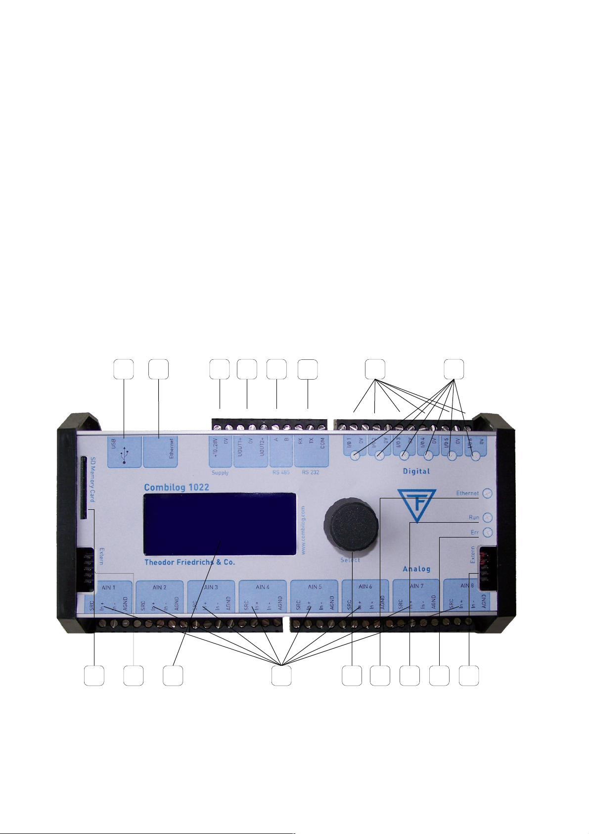
3.4 Front panel / Pin Assignment
The front panel of the data logger COMBILOG 1022 shows following elements:
Figure 3.1 Front panel
Hardware Manual COMBILOG 1022
1
14 12 11 10 9
87
6
5432
1516 139
20
Page 21
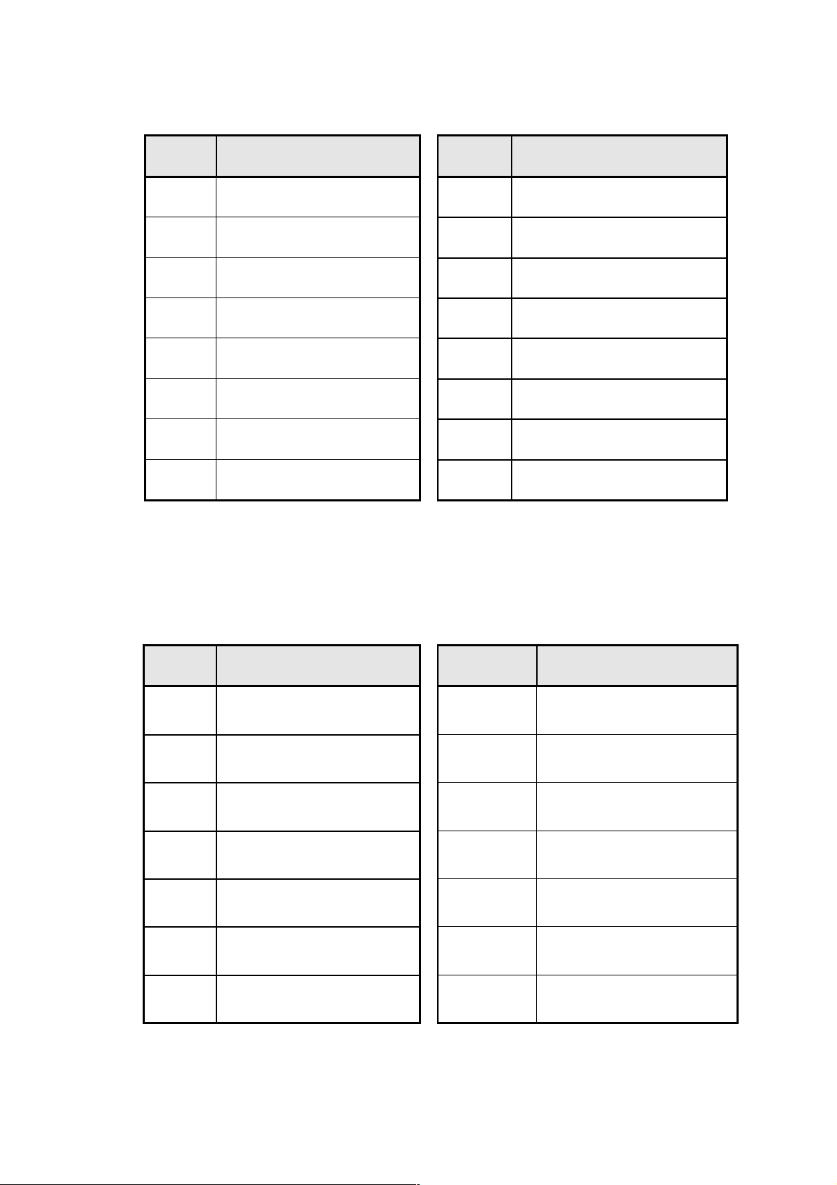
Description of the parts:
Number Description Number Description
1 USB
9
Module jack connection
2 Ethernet 10 LED ERR (red)
3 Voltage supply 11 LED RUN (green)
4 Power switch 12 Ethernet Link / Traffic
5 RS485 13 Press/rotary knob
6 RS232
14
8 analogue inputs
7 6 digital I/Os
15
LC-display
8 Status-LEDs for digital I/Os
16
Interface for memory card
Table 3.1 Description of the parts on the front of the device
Pin assignment:
Terminal Assignment Terminal Assignment
+10..30V Voltage supply + I/O + Digital I/O 1…6
0V Voltage supply - 0 V Ground for digital I/Os
A RS485-bus interface A SOURCE Source output
B RS485-bus interface B In+ Analogue input +
RX RS232 receive In- Analogue input -
TX RS232 transmit
AGND
Ground for analogue input
COM RS232 ground
UOUT 1 / 2
Power switch output
Table 3.2 Pin assignment
Hardware Manual COMBILOG 1022
21
Page 22

3.5 Connection
Connection: plug-in screw terminals
Nominal cross section: 1.5 mm² (0.02 square inch)
unifilar/fine-strand (AWG 16)
Length of wire stripping : 6 mm (0.2 inch)
Alternatively available: LP-terminals (spring loaded)
(upon request)
Protection earth: 6.3mm series tabs at rear
side of housing
The best way to pull off the screw terminals is to use a small
screwdriver, placed as a lever between terminal and the front
of the data logger.
Not more than 2 leads should be connected with one clamp. In
this case the leads should have the same conductor cross section.
Note: Wire connection is only allowed during power off.
Note: In order to avoid influences from noise on the sensor sig-
nals shielded wires should be used for the power supply, the
bus connection and the signal lines.
ATTENTION: Before final installation, a suitable protection
earth cable with terminal has to be connected to the ground
connector at the back of the data logger. Assure that the connection has a low impedance after mounting.
Hardware Manual COMBILOG 1022
22
Page 23
3.6 Power Supply
Figure 3.2 Connection of the distribution voltage
Voltage range
+10 ... +30 VDC
Power input
0.1 W typical (up to 1.1W maximum, depending on config-
uration)
Internal protector (reversible)
excess current 0.5 A M
excess voltage
Hardware Manual COMBILOG 1022
U+
U-
Versorgungsspannung
Power Supply
23
Page 24

Non-regulated DC voltage between +10 and +30 VDC is sufficient for the power supply of the data logger COMBILOG 1022.
The input is protected against excess voltage and current and
against reverse polarity. The power consumption remains approximately constant over the total voltage range, due to the integrated switching controller.
Due to its low current consumption (max. 110 mA at 12 VDC)
the data logger can also be remote-fed via longer lines. Several
data loggers can be supplied parallel within the admissible
voltage range, considering the voltage drop in the lines. The
supply lines can also be installed in one common cable, together with the bus line, if required.
In order not to charge the data logger’s supply voltage unnecessarily, a separate power supply for sensors with a large current requirement is recommended.
Hardware Manual COMBILOG 1022
24
Page 25

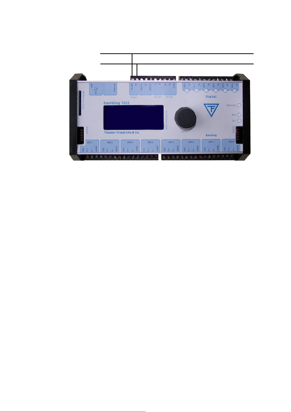
3.7 Bus Connection
In general the data logger is connected to the bus by applying
the signal leads A and B of the incoming bus cable and A' and
B' of the outgoing bus cable together to one terminal on the
module (figure 3.3).
Alternatively the bus can also be connected by a "stub cable"
as shown in figure 3.4.
Owing to the removable terminal, the bus connection to other
data loggers remains valid, even if one data logger is replaced
by another.
Figure 3.3 Connection of the data logger to the bus
Note: When connecting the logger to the bus, the two bus interfaces A and B must not be interchanged.
Note: The stub cable should be as short as possible, not
longer than 30 cm (12 inch).
Hardware Manual COMBILOG 1022
25
Page 26
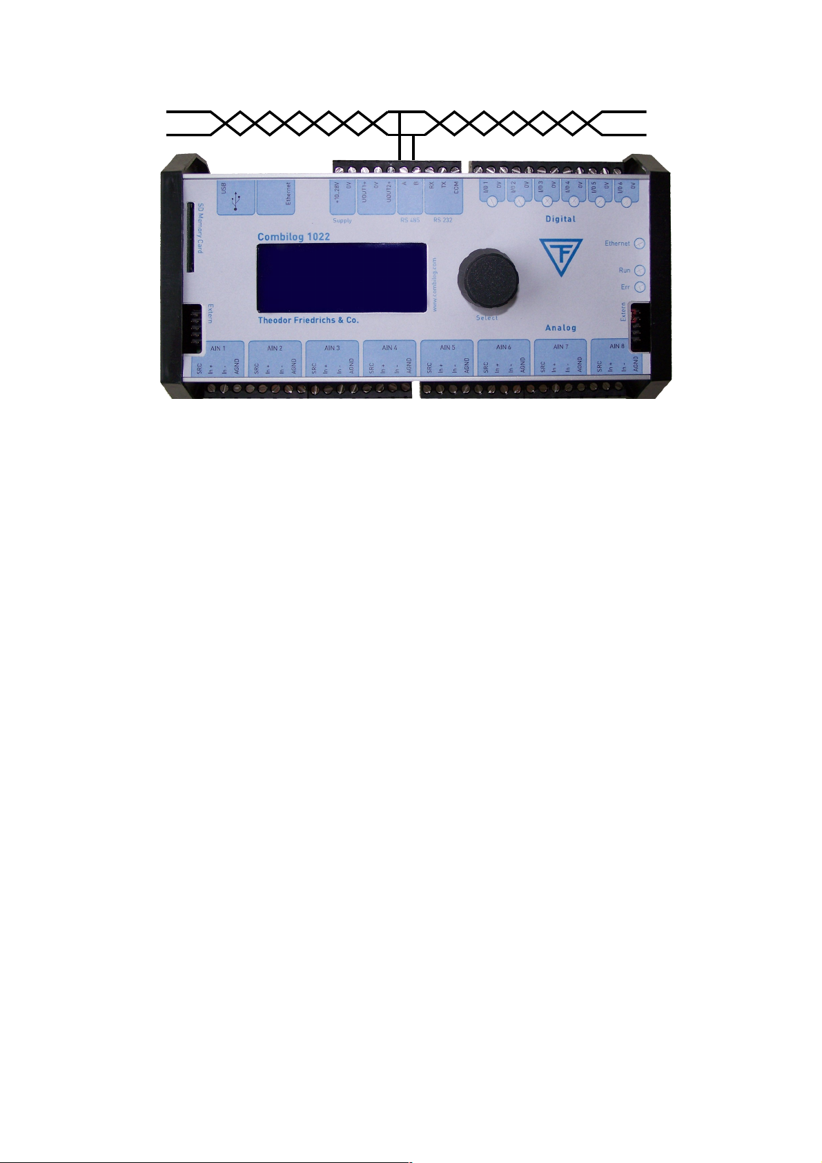
Figure 3.4 Connection of the data logger to the bus by a stub cable
3.8 Sensor Connection
The analogue and digital signal inputs and outputs are wired
according to measurement task, to the transducer (sensor) that
is used, and to the number of connected sensors. The pinout
arrangements for the various types of measurement are described in chapter 5. The respectively valid pin assignment is
determined by means of the configuration software.
Since the digital outputs are "passive" the processing of external elements always requires an external current supply. In case
of larger loads this should be independent of the data logger
supply.
At the connection of inductive loads a connection with a diode
is required in order to prevent possible damages by induced
voltage.
Hardware Manual COMBILOG 1022
26
Page 27

Following devices can be connected directly to the digital outputs: signal lamps, small relays, switching relays for larger
loads, acoustic signal installations, buzzer respectively beeper
etc., as long as the connected loads are not exceeding the values described in the technical data chapter 12.
3.9 Several Sensors at one Data Logger
The data logger COMBILOG 1022 can simultaneously receive
and process sensor signals from several different sensors. As
many sensors can be connected as there are analogue and digital signal inputs and outputs available (14 sensors max.;
8 analogue and 6 digital sensors).
3.10 Module Jack
The data logger COMBILOG 1022 has a bus connection facility
on the left and on the right side of the housing, featuring interconnection of the +10…30 VDC supply and the bus signal, for
several COMBILOG.
This kind of bus connection and of power supply is particularly
advantageous if several data loggers are mounted on one common profile rail side by side. In this case the connection via the
terminals can be dropped, except for one module.
Note: If some COMBILOG 1022 are connected using the mod-
ule jacks, the supply power has to be provided using the screw
terminals. The power supply via the module jacks has to be
used only for expansion modules.
Hardware Manual COMBILOG 1022
27
Page 28

Note: It is necessary to take care that the current at the Module
Jack is not higher than permitted. Thus, the power supply
preferably should be led to the centre of the module line. For
the same reason a 100 mA self resettable fuse protects the
module connector of the COMBILOG 1022 against short circuits.
The permanent current drawn from the module connector shall
not be higher than 100 mA.
Hardware Manual COMBILOG 1022
28
Page 29

4 SIGNAL PROCESSING
The data logger COMBILOG 1022 has eight analogue inputs
and six digital inputs/outputs. Several different sensor signals
as well as digital inputs and digital output signals can be connected and processed simultaneously.
4.1 Analogue Inputs
The analogue inputs serve to collect sensor signals, or to acquire control values respectively. They are particularly designed to measure voltages, currents and resistances.
There are 8 equal analogue inputs, each input can be configured individually.
Note: Overloads of more than ± 10 VDC will lead to false
measuring results in the according analogue input channel.
Overloads of more than ± 15 VDC will also have influence on
the measuring accuracy of the other input channels!
4.2 Digital Inputs/Outputs
The six digital inputs/outputs of the data logger can be configured - independent of each other - as inputs or as outputs.
The current status (in/out) is signalized by one LED each.
Hardware Manual COMBILOG 1022
29
Page 30
As inputs the I/Os can be used for collecting feed-back signals,
for measuring frequencies, as counters or for receiving special
serial 8-bit-Graycode signals. Status information can be issued
by the outputs. Thereby host-controlled or process-controlled
status outputs are possible.
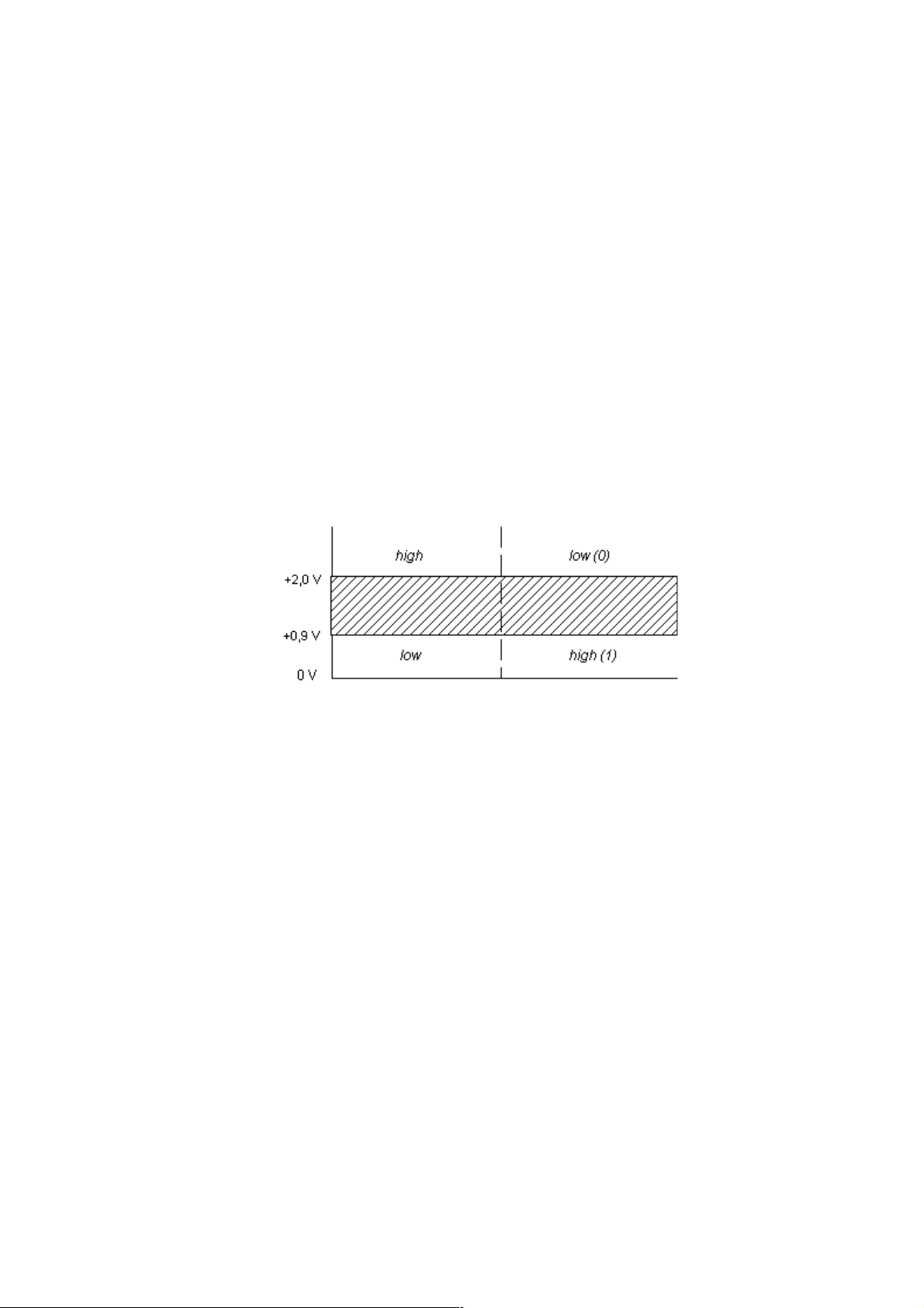
The digital inputs have an excess voltage protection (transil diodes), with nominal threshold 30 V. Input voltages between
2.0 VDC and 30 DC are interpreted as logic LOW ("0"), input
voltages lower than 0.9 V as logic HIGH ("1"). The maximum
input current is 1.5 mA.
Figure 4.1 Definition of signal levels and logic levels
The outputs are open-collector type with a maximum voltage of
30 VDC and a maximum current of 100 mA.
4.3 Power Switch
The data logger Combilog 1022 has two power switches which
act as voltage supplies for external sensors.
A power switch can be assigned to an analogue channel and
configured with a lead time (see chapter Power Switch ).
The supply is switch on with a configurable time before the selected analogue input channel will be measured.
Hardware Manual COMBILOG 1022
Signal level Logical level
30
Page 31

4.4 Internal Reference Voltage, Offset- and Drift Correction
An internal reference voltage serves to adjust the entire analogue signal processing automatically.
Especially for measurement of extreme low voltages, currents
and resistances, the configuration software features an additional compensation of temperature drift. With current- and
voltage measurement, this is realized by an internal offset
measurement. The measured offset is subsequently applied to
correct the measured values. For Maximum accuracy with current measurement (temperature drift less than 25 ppm/K) it is
recommended to accomplish the measurement via an external
shunt with a correspondingly low temperature coefficient (< 5
ppm/K). For this purpose, the input channel has to be configured as a voltage input.
For resistance measurement, a drift correction requires an additional input channel which has to be equipped with a suitable
reference resistance. This resistance should have a low temperature coefficient (< 5 ppm/K). In the configuration table, this
channel has to be defined as a reference channel with resistance input for drift correction, whereby the nominal value of this
resistance (at 20°C) has to be indicated.
Using the above described methods, the analogue inputs can
almost completely be kept free from temperature drift.
Hardware Manual COMBILOG 1022
31
Page 32

4.5 Internal Processing
Next to collecting the analogue input signals, the analogue multiplexer at the input of the circuit collects the internal reference
voltage. All these values are then transmitted to the programmable amplifier PGA, where the signals are amplified according to the kind and type of the connected sensors and then
supplied to the A/D converter.
The A/D converter digitalises all incoming signals with a definition of 16 bit and at a rate that can be preset for the module by
the user. The Sigma-Delta-procedure used for the A/D-conversion guarantees a high accuracy and a high linearisation. The
A/D-converter processes an integrated amplifier with the amplifier stages of 1, 2, 4, 8, 16, 32 and 64. For very small signals,
the module switches to an additional amplifier with amplifier
stages of 100, 200, 800 and 3200. The amplification in alignment with the accuracy and resolution of the calculated measuring values results from the selection of the measuring range
which will be configured by assistance of the configuration software.
This software also configures the ADC internal low pass filter,
depending on the mains frequency and desired ADC frequency
(selectable between 10 and 400 Hz). Standard configuration for
the low pass filter is 50 Hz.
The microprocessor µP now edits the measuring signal in digital form.
First the processor linearises and scales the signal and holds it
ready for transmission via bus in programmable units. Further
the processor monitors the measured values for excess of
freely programmable threshold values. Thus a monitoring of
Hardware Manual COMBILOG 1022
32
Page 33

failure or breaking of the sensing element or short-circuit can
also be realised. The data logger can be activated - by means
of appropriate configuration - to provide a corresponding signal
at the digital I/O in case of alarm. The digital I/Os are directly
addressed and monitored respectively by the microprocessor
µP.
Hereafter an arithmetical averaging of the values is carried out.
The average interval is the same for each channel and is adjustable in steps of 0.5, 1, 2, 3, 4, 5, 10, 15, 20 and 30
seconds, 1, 2, 3, 4, 5,10, 15, 20, 30 minutes, resp. 1, 2, 3, 4, 6,
8 and 12 hours. The calculated average values are finally
stored in the memory.
The special user program, the data for configuration, linearisation and scaling etc. that are required by the processor µP for
all tasks are retentively stored in a EEPROM.
The timing control of the data processing is realised by an internal real time clock buffered by Gold cap capacitor.
4.6 Scan Rate and Power Consumption
The A/D-converter digitalizes every signal at a rate that can be
preset by the user. The scan rate can be selected between
0.25 sec. and 1 hour. In this selected time period all configured
channels are scanned and processed correspondingly. The
power consumption of the data logger COMBILOG 1022 depends on this scan rate. Between the measuring cycles the
data logger will be set into a so-called “Sleep-Mode“. During
this mode the data logger needs only about 20 mA with supply
for the serial lines being active.
Note: A scan rate of 0.25 s causes an unsignificant higher variation of instantaneous values but does not affect the averaging.
Hardware Manual COMBILOG 1022
33
Page 34

4.7 Signal Processing
Arithmetical averaging is carried out using several measuring
values. The averaging interval, which is the same for all channels, can be set to one of the values 0.5, 1, 2, 3, 4, 5, 10, 15,
20, 30 seconds or 1, 2, 3, 4, 5, 10, 15, 20, 30 minutes or 1, 2,
3, 4, 6, 8, 12 hours respectively. The calculated values are finally stored in the memory.
With the configuration software the kind of averaging is selectable: Normal averaging or averaging of wind direction (consideres the discontinuity at NORTH). For counter variables not
the average, but the number of pulses is calculated.
A change of the average interval can be initiated by certain program conditions, thus featuring temporary higher time resolution of measured signals.
Hardware Manual COMBILOG 1022
34
Page 35

5 FUNCTIONAL DESCRIPTION
The data logger COMBILOG 1022 has a total of 32 logical
channels for the collection, processing and output of various
kinds of sensor information. These 32 channels can be configured as:
Analogue Input Channel
Digital Input Channel
Digital Output Channel
Arithmetic Channel
Setpoint Channel
Alarm Channel
For each channel various kinds of channel information and processing functions can be determined. The table in appendix C
gives a survey of the channel set-ups with the data logger
COMBILOG 1022. The channel set-ups are carried out by
means of the configuration software.
Hardware Manual COMBILOG 1022
35
Page 36

5.1 Analogue Input Channel
The Analogue Input Channel collects and processes the signals of the most common types of sensors. A large number of
standardised sensors is already stored in the COMBILOG internal sensor data base. Further sensors can be added by the
user.
Following measuring principles are provided:
Voltage measurement
Current measurement
Resistance measurement
Temperature measurement with thermocouples
For each of these principles the data logger COMBILOG 1022
offers several types of measurement. For voltage measurement the types of measurement single-ended and differential
can be used. Currents up to 25 mA are directly measured by
the data logger. Current measurements of more than 25 mA
can be carried out by measuring voltage drop at an external
shunt. Resistance measuring can be carried out in 2-, 3- and 4wire technique.
Each analogue input channel can be assigned an individual
sample rate (see chapter Single Channel Configuration ).
Hardware Manual COMBILOG 1022
36
Page 37

5.1.1 Voltage Measurement
Two methods are available for voltage measurement: singleended and differential measurement.
With the single-ended type the voltage to be measured is connected between an analogue input (In+) and analogue ground
(AGND). Differential measurements are realized by using two
analogue inputs (In+ and In-). Measuring range is between 0
and ±10 V.
Note: With differential measurements both voltages have to be
within 10 V referred to AGND (Common-Mode-Range).
It is recommended to connect the In- to A
GND
with a high ohmic
resistance.
Hardware Manual COMBILOG 1022
37
Page 38
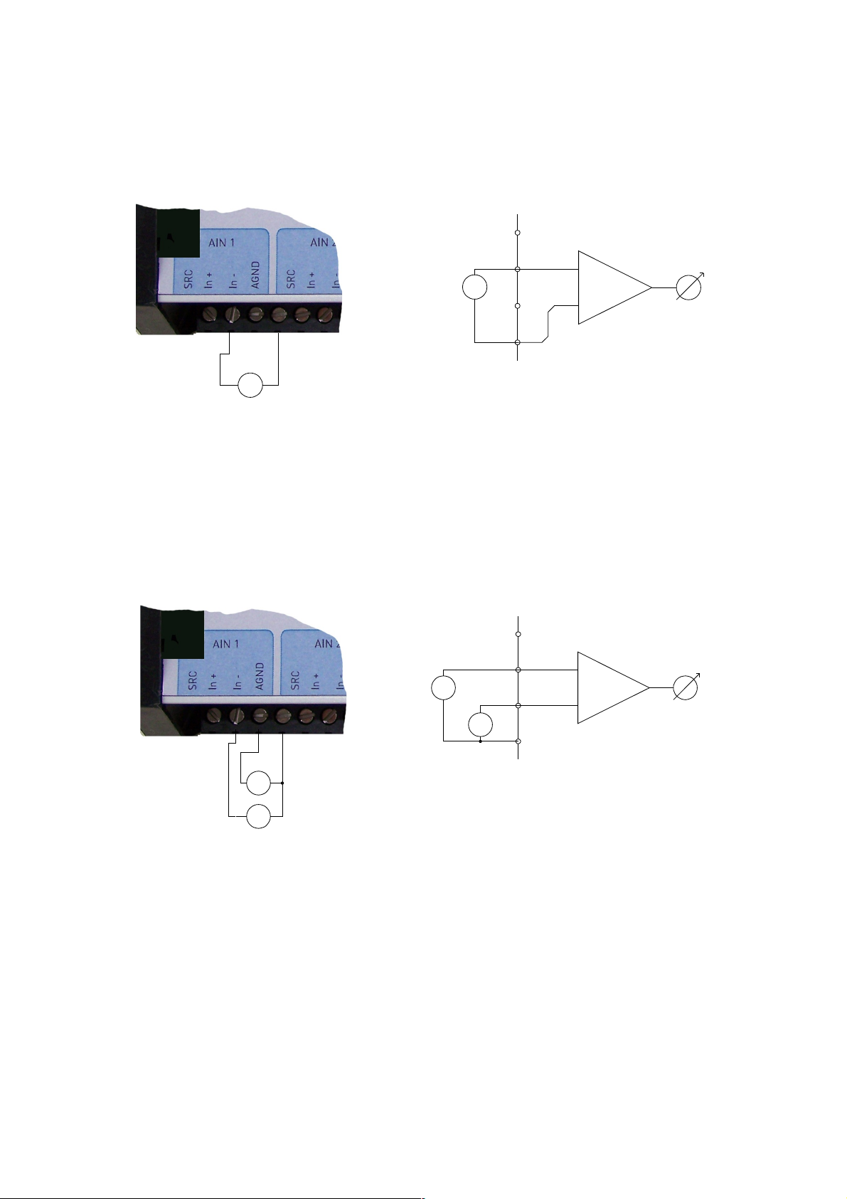
Voltage Measurement
Figure 5.1 Voltage measurement - single-ended
Figure 5.2 Voltage measurement - differential
Hardware Manual COMBILOG 1022
Source
IN+
IN-
AGND
=
+
-
U1
U
U = U1
=
+
-
Anschlussschema Schaltung
Source
IN+
IN-
AGND
=
U
U = U2-U1
Anschlussschema Schaltung
= =U1U2
=
U1
U2
CircuitConnection scheme
Connection scheme Circuit
38
Page 39

5.1.2 Current Measurement
For current measurement the current source is connected
between an analogue input (In+) and analogue ground (A
GND
).
The load required for measurement is controlled by an internal
resistor R
int
to 100 Ω. The power capacity of this shunt is lim-
ited to 125 mW. This results in a measuring range of 25 mA
maximum.
Higher currents can be measured by means of an external resistor which is connected parallel to the current source to the
analogue signal input and analogue ground (A
GND
). The power
capacity of this external shunt has to be adapted to the current
source to be measured, so that the voltage occurring at the
analogue input does not exceed +10 V. The analogue input is
configured as voltage input. The voltage has to be divided by
R
ext
.
Note: The precision of the current measurement with external
shunt depends on the precision of the resistor being used.
Note: The input resistance of the current measurement channel depends on the current to measure!
Hardware Manual COMBILOG 1022
39
Page 40

Current Measurement
Figure 5.3 Current measurement with internal shunt
Figure 5.4 Current measurement with external shunt
Hardware Manual COMBILOG 1022
Source
IN+
IN-
AGND
I
U
I = U / Rint
Anschlussschema Schaltung
Rint
Source
IN+
IN-
AGND
I
U
I = U / Rext
Anschlussschema Schaltung
Rext
Rext
Connection scheme Circuit
Connection scheme Circuit
40
Page 41

5.1.3 Resistance Measurement
Resistance measurement is carried out by means of voltage
measurement at a resistor, measuring the resulting voltage
drop. The constant current required for the resistance measurements is provided by the internal supply of the data logger.
For this purpose the sensor module connects a supply point internally with the analogue measurement input via a reference
resistor Ro. The voltage drop Uo via resistor Ro is required as a
reference for further signal processing by the module. The resistance value of the sensor can be calculated from the input
signals Ui as a multiple of the reference resistor Ro. Measuring
range is between 0 and 20 kΩ.
Note: The data logger COMBILOG 1022 supports resistance
measurement in 2-, 3- and 4-wire technique. With resistance
measurement in 2-wire technique the supply lines cause an additional voltage drop, thus distorting the measuring result and
influencing the measuring accuracy. Therefore it is necessary
to pay attention especially with resistance measurement in 2wire-technique. Wires with impedance as low as possible
should be used. Make sure that the leads are well connected to
the data logger and the sensor. With resistance measurement
using 3-wire technique the potential on the supply lines will be
subtracted by software. Therefore 2 measurements are necessary, resulting in double measuring time. With resistance
measurement in 4-wire technique the drop of potential is picked
up directly at the sensor, so that the measuring results are not
influenced by the supply lines.
Hardware Manual COMBILOG 1022
41
Page 42

Resistance Measurement
Figure 5.5 Resistance measurement in 2-wire technique
Figure 5.6 Resistance measurement in 3-wire technique
Figure 5.7 Resistance measurement in 4-wire technique
Hardware Manual COMBILOG 1022
Source
IN+
IN-
AGND
U
Rx = U/U0 * R0,
Anschlussschema Schaltung
Rx
Rx
Messwiderstand
RL
RL R0
=
U0
Rx = 2 * RL
Source
IN+
IN-
AGND
U1
Rx = (U1/U0-2*U2/U0) * R0,
Anschlussschema Schaltung
Rx
Rx
Messwiderstand
RL
RL R0
=
U0
U2
Rx = 0
Source
IN+
IN-
AGND
U2 - U3
Rx = (U2 - U3)/U0 * R0,
Anschlussschema Schaltung
Rx
Rx
Messwiderstand
RL
RL R0
=
U0
Rx = 0
Connection scheme Circuit
Connection scheme Circuit
Connection scheme Circuit
42
Page 43

Temperature Measurement with Thermocouple
Thermocouples consist of two “thermoelectric wires” made of
different materials (e.g. platinum and platinum rhodium) that
are welded to each other at one end. If the contact and the other ends of the thermoelectric wires have different temperatures,
a “thermoelectric voltage” Uth appears at the contact of both
thermoelectric wires. This voltage is largely proportional to the
temperature difference. It can be measured and used for
temperature measurement purposes. With data logger
COMBILOG 1022 the thermoelectric voltage is measured
differentially.
Since thermocouples can only measure a temperature difference (difference between temperature to be measured and
temperature at the connecting terminals on the sensor
module), a terminal temperature (internal cold junction compensation, TC
int
) or a known temperature reference (external
cold junction compensation, TC
ext
) also have to be determined.
With measurement of temperature with internal cold junction
compensation an additional temperature sensor is necessary to
measure the temperature ϑ
k
at the “cold” terminal. A special
cold junction terminal is available, where a Pt100 temperature
sensor is integrated directly in the terminal block. The temperature of the test point is determined on basis of linearization
trace to ϑ
x
= Lin(Ux+Lin
-1
ϑ
k
).
Hardware Manual COMBILOG 1022
43
Page 44

If the temperature is measured by external cold junction compensation, a second thermocouple of the same type is required, which is connected in series with the first one. The polarity is selected so that the thermoelectric voltages subtract
each other. The second thermocouple is set to a fixed refer-
ence temperature ϑr (mostly ϑ
r
= 0°C). The data logger then
calculates the temperature at the measuring position by means
of the linearisation curve as ϑ
x
= Lin(Ux+Lin
-1
ϑ
r
). The data log-
ger will be informed about the reference temperature ϑ
r
via the
configuration software (“cold junction temperature”).
Hardware Manual COMBILOG 1022
44
Page 45

Temperature Measurement with Thermocouple
Figure 5.8 Temperature measurement with internal cold junction
compensation by special terminal clamp ICJ 104
Figure 5.9 Temperature measurement with external cold junction
Hardware Manual COMBILOG 1022
Source
IN+
IN-
AGND
U1
ϑ
x = Lin (U2 + Lin-1 ϑk), ϑk = Lin (U1)
Anschlussschema Schaltung
1M
Ω
ϑ
k
R0
=
U0
U2
ϑ
x
ϑ
x
zusätzliches
Kaltstellenmodul
Source
IN+
IN-
AGND
ϑ
= Lin (U1 + Lin-1 ϑp)
Anschlussschema Schaltung
1M
Ω
ϑpϑ
1M
Ω
ϑ
p
ϑ
U1
Connection scheme Circuit
Connection scheme Circuit
45
Page 46

5.2 Digital Input Channel
The following functions can be realized by means of the Digital
Input Channel:
Digital status recording
Frequency measurement
Counter
8 bit Graycode transducers, Type 4122 / 4123
8 bit status input, with additional (external) module
The above mentioned functions are based on incremental
measurements except the digital status and Graycode recording. Incremental measuring means to count while measuring.
Pulses are counted e.g. from wind speed sensors.
Furthermore it is possible to connect up to 6 sensors with a
serial 8 bit Graycode output to the COMBILOG 1022, e.g. wind
direction sensor type 4122 / 4123.
By means of an external module type 1025 8 bit status signals
can be measured at each input. This module converts the 8 bit
into a serial signal, and the COMBILOG will compose it to 1
byte again.
Hardware Manual COMBILOG 1022
46
Page 47

5.2.1 Digital Status Recording
For the acquisition of digital status information (on/off,
closed/open, left/right, etc.) the signal fed to the digital input is
collected and is held ready for further processing in the data
logger COMBILOG 1022 or for transmission via bus.
The digital input is set (switch closed) as long as the signal
voltage remains under the threshold value of 1.0 V. The digital
information can be scanned as 1/0 information via bus.
Figure 5.10 Digital status recording
I/O 1
status
"0" "1" "0" "1"
signal diagram:
Hardware Manual COMBILOG 1022
Anschlussschema Schaltung
0V
I/O
+ 10V .. 30V
Connection scheme
Signal diagram:
Circuit
47
Page 48

5.2.2 Frequency Measurement
With frequency measurements the data logger counts the pulses within a certain time interval at the digital input. The user
can preset this time interval by setting the time base (TB) in the
range between 0.1 sec and 10 sec. The frequency is calculated
by the sensor module from the number of pulses and the time
base TB as:
frequency f =
number of impulses per time interval TB
length of time intervall TB
Hz
With frequency measurements always the negative signal edge
(1 -> 0) is counted.
The lower the frequency f, the larger the interval between two
pulses, and the larger the time base TB has to be. On the other
hand the updating of the measured value decreases with an increasing time base. Thus the time base should be selected so
as to make TB ≈ 1/fu, fu being the lowest frequency respectively
the smallest change in frequency to be determined by the data
logger. The error with frequency measurements thus amounts
to ∆f = fu = 1/TB.
Note: The high-end frequency for the frequency measurement,
i.e. the highest frequency to be measured. It is 4000 Hz.
Hardware Manual COMBILOG 1022
48
Page 49

Frequency Measurement
Figure 5.11 Frequency measurement
I/O 1
time base
TB TB TB
counting
1 2 3 1 2 3 1 2 3 1
measurand
(TB = 5 sec)
signal diagram:
- high level:
TB TB TB
1 2 1 1 2
- low level:
0,6 Hz 0,6 Hz 0,6 Hz
0,4 Hz 0,2 Hz 0,4 Hz
pulse
I/O 1
time base
counting
measurand
(TB = 5 sec)
pulse
Hardware Manual COMBILOG 1022
Anschlussschema Schaltung
0V
I/O
+ 10V .. 30V
f
f
Connection scheme
signal diagram:
Circuit
49
Page 50

5.2.3 Progressive Counter
When configuring a digital input as a progressive counter the
data logger COMBILOG 1022 constantly monitors the digital
input for a signal variation. If a negative signal edge (1 -> 0) occurs at the input, the current result is increased by 1.
The values may range from -2
31
to +(231-1) (about -2.1 to +2.1
billion). Above +231-1 the counting continues with -231. The values can be reset to zero via the bus interface or internally after
the procedure of the averaging interval.
Note: The maximum counting rate is 2400 Hz.
Note: After a voltage cut-off the counter is reset to zero.
Figure 5.12 Progressive Counter
+1 +1 +1 +1 +1
n+1 n+2 n+3 n+4 n+5
signal diagram:
I/O 1
counting
counting
measurand
pulse
Hardware Manual COMBILOG 1022
Anschlussschema Schaltung
0V
I/O
+ 10V .. 30V
Connection scheme Circuit
50
Page 51

5.3 Digital Output Channel
5.3.1 Digital Status Output
The digital output channel supports:
digital status output, host-controlled
digital status output, process-controlled
Via the digital inputs/outputs I/O 1 to I/O 6 on the data logger
COMBILOG 1022 digital status can be output in digital form,
according to the configuration. A typical case of application
would be e.g. the local output of an acoustic or optical signal in
case a limiting value is exceeded or undershot by a measured
value.
All outputs are open-collector.
The supply voltage can range from 10 up to 30 VDC. It has to
be either supplied externally or taken from the power supply of
the data logger.
The status of the digital output can be scanned as 1/0 information via bus.
With the host-controlled digital status output, the digital output
is set according to the status information received by the data
logger via bus.
With the process-controlled output of status information the
data logger monitors measured values, resp. sensor channels
from excess of default threshold values. The digital output is
set if one or several threshold conditions are fulfilled.
Hardware Manual COMBILOG 1022
51
Page 52

The thresholds can be freely defined by the user. The user can
also preset the logical signal level (see also the configuration
software COMBILOG.EXE).
Thus it is possible to activate a digital output depending on a
specified time or periodically. This can be realized in connection with an arithmetic channel, that can calculate the time or a
time interval from the internal real time clock. A typical application is to switch off a modem after a specified time to reduce
the power consumption of battery powered systems.
Figure 5.13 Digital status output
I/O 1
status
"0" "1" "0" "1"
signal diagram:
Hardware Manual COMBILOG 1022
Anschlussschema Schaltung
I/O
U+
Connection scheme Circuit
52
Page 53

5.4 Arithmetic Channel
By means of the arithmetic channel sensor channels and constants can be connected with each other via arithmetic operations. The result is allocated to the arithmetic channel. The formula can contain up to 20 operands. The calculation is performed with a stack depth of 20. The value is handled as a
4-byte floating point format with 24 significant bits according to
IEEE, standard 754. The full scale is –1037 to +1037.
A typical application for the arithmetic channel is e.g. the determination of a value that cannot be measured directly, but
calculated from other values (e.g. power as a product of
voltage and current). Or the arithmetic channel is used for further mathematical preparation of a measuring signal, in order
to obtain a particular desired format, linearisation or similar.
Special functions for which the existing commands are not sufficient, can be carried out by a user specific download program
for the COMBILOG 1022. For this case, some implemented
special functions can be used for assistance.
To integrate a serial channel the special function 1 is to be
used. The serial channel converts an ASCII telegram into a
float value. Two variants are possible to chose, constant length
or variable length. With constant length the conversion starts at
startposition and ends at startposition + length. With variable
length the conversion starts at startposition and ends at the first
delimiter character.
Should the conversion be unsuccessful the default value will be
taken.
The call to special function 1 is defined as:
Hardware Manual COMBILOG 1022
53
Page 54

spez1(INTERFACE; TYPE; START; VAR; DEFAULT)
• INTERFACE
• 1: RS232
• 2: RS485
• TYPE
• 1: constant length
• 2: variable length
• START: start position (starting with '0')
• VAR
• for TYPE = 1: value length
• for TYPE = 2: delimiter character (ASCII value)
• DEFAULT: on error this is value will be returned
In defining more than one arithmetic channel with this function
you can extract more than one value from one ASCII telegram.
To convert a variable value with start position 10, delimiter #,
interface RS485 and default value –1 from
“Value:_0023,6697#END” the call to spez1() should be
spez1(2; 2; 10; 35; -1) and the result is 3.6697.
With special function spez2() some special meteorological values can be calculated. The following functions are defined:
●spez2(air pressure; height; 1);
Calculates the air pressure on sea level out of air pressure at
given height.
●spez2(app_wind; fair_wind; wind_angle; 2);
Calculates the true wind speed out of apparent wind, fair wind
and the enclosed angle.
●spez2(temperature; radiance_balance; saturation_deficit ;
wind_speed; 3);
Calculates the evaporation acc. to Penman-Monteith.
Hardware Manual COMBILOG 1022
54
Page 55

Note: The calculation time of an Arithmetic Channel is
min 0.2 ms. The overall calculation time is the sum of the times
of all operands in the formula plus 0.2 ms. This has to be taken
into account when calculating the sample rate.
Hardware Manual COMBILOG 1022
55
Page 56

Arithmetic Operators
operations abbreviation time
Addition + 0.26 ms
Subtraction - 0.26 ms
Multiplication * 0.26 ms
Division / 0.26 ms
Modulo % 0.24 ms
Truncate value trunc 0.16 ms
Minimum value min 0.16 ms
Maximum value max 0.16 ms
Absolute value abs 0.16 ms
Square root sqrt 0.26 ms
Exponential function to base e exp 0.56 ms
Logarithm to base e In 0.26 ms
Logarithm to base 10 log 0.26 ms
Sine sin 0.44 ms
Cosine cos 0.44 ms
Tangent tan 0.66 ms
Inverse sine arcsin 0.70 ms
Inverse cosine arccos 0.70 ms
Inverse tangent arctan 0.62 ms
Lowest value from a selection Low 0.30 ms
Highest value from a selection high 0.30 ms
X
Y
power 1.64 ms
Integrator integ 0.18 ms
Differentiator deriv 0.18 ms
Read from external module read
Write to external module write
Time /seconds of the day) SecondsOfDay 0.18 ms
Sample rate SampleTime 0.18 ms
Free space on SD-Card SDSpace 0.20 ms
Hardware Manual COMBILOG 1022
56
Page 57

Free space in RAM RAMSpace 0,1 ms
Application specific function 1 spec 1
1)
Application specific function 2 spec 2
1)
Application specific function 3 spec 3
1)
Application specific function 4 spec 4
1)
1)No specification available as the time depends to the specific function and the program.
Table 5.1 Arithmetic operators and processing times
The times given in the above table are based on an operating frequency of 48 MHz.
Remarks:
Division (/)
When dividing by zero, the positive full scale (+1037) will be
assigned to the Arithmetic Channel if the numerator is
positive and the negative full scale (-1037) will be assigned
if the numerator is negative.
Square root (sqrt)
The square root of a negative number is zero.
Logarithm to Base e (In)
For a value ≤ 0 the negative full scale will be assigned to
the Arithmetic Channel.
Logarithm to Base10 (log)
For a value ≤ 0 the negative full scale will be assigned to
the Arithmetic Channel.
Arc functions (sin, cos, tan)
The arc values must be taken in radians (2π = 360°). If
calculating the tangent, the positive full scale will be as-
signed to the Arithmetic Channel for the arc value
2
π
and
the negative full scale for the arc value -
2
π
.
Inverse functions for sin (arcsin), cos (arccos), tan
(arctan)
Hardware Manual COMBILOG 1022
57
Page 58

The results of the inverse functions are given in radians
(2π = 360°). At the function arcsin the value +
2
π
will be
assigned to the Arithmetic Channel for a value >1 and the
value –
2
π
will be assigned for a value <-1. At the function
arccos the value 0 will be assigned to the Arithmetic
Channel for a value >1 and the value will be assigned for a
value <-1.
Minimum and maximum of a channel value (min, max)
With this function the minimum and maximum value of a
channel appeared since the last reset has been triggered
off can be determined (“pull-pointer-function”). The result
value can be reset to the actual value of the measured
channel via the bus or at the end of the average interval.
The functions read and write enable the data logger to re-
ceive measured values from other modules connected to
the same bus, resp. to send values to them (master function)
Note: Logic combinations, e.g. if-then relations, are not yet
possible respectively would require a user-specific software
(upon request).
Hardware Manual COMBILOG 1022
58
Page 59

5.5 Setpoint Channel
This channel features transmission of values via bus to the
data logger COMBILOG 1022. The values are allocated to the
setpoint-channel and are thus at the disposal of the data logger
for further processing.
A typical application for the setpoint-channel is e.g. the dynamic variation of control thresholds.
5.6 Alarm Channel
The Alarm Channel has the same features as the process-controlled digital output channel, the only difference is that the
status information is not output locally at the digital output, but
can only be scanned via the bus.
5.7 Serial Channel
The serial channel output transmits the ASCII formatted strings
of the logging channels onto the configured interface. The serial channel function can be configured using the build in web
page (see chapter 12.9)
5.8 Threshold Values
The user can preset the conditions for process-controlled digital status output on the data logger and for the output of an
alarm signal via bus. This is carried out by means of the configuration software COMBILOG.EXE.
Hardware Manual COMBILOG 1022
59
Page 60

5.9 Error Handling
The data logger COMBILOG 1022 can detect independently
certain defects, which are result of a line break, short-circuit or
communication interrupt, for example. For these defects the
user can preset a certain behaviour for the data logger via the
configuration software.
In case of a sensor failure the last valid value can be maintained, set to the corresponding limits or set to a default value.
Furthermore the COMBILOG 1022 can send messages via modem or SMS automatically to report errors or other conditions,
e.g. if the data memory capacity becomes zero.
Hardware Manual COMBILOG 1022
60
Page 61

6 DISPLAY / MENU OPERATION
6.1 Display and Operation
The data logger COMBILOG 1022 has a display with 4 lines of
16 characters each, in order to allow the indication of the
measured values of each channel. Furthermore the settings of
the data logger can be recalled and changed if desired (therefore the input by the press/ rotary knob must be unlocked; refer
to the corresponding section 6.2 “Menu Items“)
The operation is performed via the combined press/rotary knob
at the right side of the display. By turning the knob the menu
items or informations can sequentially be indicated. A confirmation or a call of a function is performed by pressing the knob.
6.2 Menu Items
In the following diagrams all display pictures with the corresponding operation steps are indicated. Following symbols are
used for the operation steps:
Symbols:
turn the knob clockwise
turn the knob counter clockwise
press the knob briefly (confirmation)
press the knob for approx. 1 second minimum
(abortion)
Hardware Manual COMBILOG 1022
61
Page 62

Main menu
Note: The number, designation and indication of the measured
value of the channels depend on the configuration.
Hardware Manual COMBILOG 1022
62
Page 63

Configuration menu
Note: If the push/turn selection knob is pressed at any point in
the configuration menu for about 1 second you will return to the
initial position in the main menu.
Hardware Manual COMBILOG 1022
63
Page 64

Setting of the display backlight
Note: The value of the display backlight can be set in steps
from 0 % to 100 %. With low values the display will be set dark
and with the value 100 % it will be set to maximum brightness.
Hardware Manual COMBILOG 1022
64
Page 65

Setting the scan rate and the averaging interval
Configuration menu
Note: The scan rate determines after which time interval the
measured values of the channels will be measured again. Scan
rate is selectable between 0.5 s and 1 h.
At “Averaging“ the averaging interval can be set. It determines
the time interval for the averaging of the measured values. Averaging interval is selectable between 1s and 12h.
In the example the measured values will be measured again
every 10 seconds and after 60 seconds the average value will
be calculated (here by means of 6 measured values).
Hardware Manual COMBILOG 1022
65
Page 66

Setting of the Automatic Switch Off and the
LED Display
Configuration menu
Note: With the automatic switch off function the data logger
can be set to the saving mode if no operation is made by the
press/ rotary knob in a certain time interval (30 seconds). In
this case the display will be set off until a further operation
takes place.
If “LEDs“ is set to ON the LED-display is switched on and the
two LEDs RUN and ERR on the front of the data logger show
the actual operating state (mode) of the data logger. With the
selection OFF the LEDs will be switched off.
Hardware Manual COMBILOG 1022
66
Page 67

Setting of the Baud Rate and the Address
Configuration menu
Note: Possible values for the baud rate are 2400, 4800, 9600,
19200 and 38400 bps. Additionally to the baud rate the parity
can be set . Possible values are N (no parity), E (even parity)
and O (odd parity).
For the address a value between 1 and 127 can be set.
Hardware Manual COMBILOG 1022
67
Page 68

Lock or unlock the press/rotary knob input
Configuration menu
Normally the changing of configuration parameters by the
press/rotary knob is locked (disabled). To change the parameter the press/rotary knob must be unlocked (enabled).
Note: If no operation is performed at the data logger for approx. 30 seconds it will return to the main menu and the
press/rotary knob input will automatically be locked.
Hardware Manual COMBILOG 1022
68
Page 69

Network settings
If the powersave feature for the ethernet interface is enabled
no connection can be established using this interface.
Due to the relatively high power consumption it is essential for
low power applications like mobile battery powered systems to
have the ethernet powersave function enabled.
The IP, gateway and netmask selection modifies the selected
address. The flashing number is actually selected for modification. Rotating the knob counts the number up or down while
pressing the knob selects the next number.
Hardware Manual COMBILOG 1022
69
Page 70

Channels settings
In order to change the values the press/rotary knob must be
pressed. Thereby a cursor will be set on the first character of
the value. Pressing the knob again moves the cursor one character to the right. The value at the place of the cursor can be
altered by turning the knob. Clockwise (=upwards) or counterclockwise (=downwards).
Note: Depending on the type of channel different settings can
be made.
(1) the definition of offset and factor is possible for the ana-
logue input channel, the digital input channel and the digital output channel. These settings are used to convert the
measurement value from the unit of the measured value to
the unit of the measurement display.
(2) For the setpoint channel a setpoint value can be defined
if this is allowed by the configuration software
COMBILOG.EXE. This value can be used by the data log-
ger for further processing (e.g. for the arithmetic channel).
For the arithmetic channel and the alarm channel no settings
can be made.
Hardware Manual COMBILOG 1022
70
Page 71

Display and delete the data memory
Main menu
The display shows the number of stored datasets and the maximum capacity of the data memory. The fourth line shows the
approximate time until the data memory is filled. This time is
displayed in days (d) or hours (h) and is calculated by the data
logger assumed that the average interval is constant.
Hardware Manual COMBILOG 1022
71
Page 72

Setting of the date and time
In order to change the date and the time the press/rotary knob
must be pressed when the time
(1)
respectively date
(2)
is displayed. For this purpose a cursor will be set on the first character of the date respectively time indication. Pressing the knob
again will move the cursor one character to the right. The value
at the place of the cursor can be altered by turning the knob.
Note: The time will be stopped if the press/rotary knob is
pressed in the main menu, date and time display. The time will
continue running if the date or time setting is confirmed by
pressing the knob.
Hardware Manual COMBILOG 1022
Configuration
Date / Time
Time change?
Combilog 1022
Date / Time
02.01.2009
00:05:10
Configuration
Date / Time
Date change?
Change+
Change-
Change+
Change-
Configuration
Date / Time
02.01.2009
Configuration
Date / Time
00:05:10
(2)
(1)
72
Page 73

6.3 SD-Card
If a SD-card is inserted into the card slot an additional menu
item is displayed in the main menu. Choosing this menu item
one can update the firmware of the data logger or eject the SDcard.
Hardware Manual COMBILOG 1022
SD-Card
>remove card
update files
Main menue
>SD-Card
Data recorder
Auto Powerdown
FIRMWARE
UPDATE
AND
RESTART
Change +
Change -
Change+
Change-
Do you want to
update with:
COMBL.BIN
[Yes/No]
Updatefiles
COMBL.BIN
73
Page 74

6.3.1 Remove Card
If a SD-card is configured as logging destination the card has
to be logged off of the system before removing it. Otherwise
written data can be lost.
For card removal you choose this menu item. The card will be
logged out of the system without any further question.
6.3.2 Firmware Update
Using the menu item 'update files' one can start the firmware
update procedure. Therefore a special firmware update file
must reside in the directory 'updates' on the SD-card.
After choosing ' update files' all files in the directory 'updates'
are presented for selection.
Selecting one file starts the update procedure after a security
question. If the file contents for some reason seems to be corrupted, the firmware update stops. If there was no error during
file checking the data logger starts the reprogramming and
starts a system reboot during which the new image is written
into the program flash.
Warning:
As a firmware update is a critical process a backup of all logged
data and of the configuration is highly recommended!
Hardware Manual COMBILOG 1022
74
Page 75

7 DATA STORAGE
7.1 General Remarks to Data Storage
The COMBILOG 1022 is able to store the calculated mean values. Data storage with the COMBILOG 1022 can be accomplished in three different manners:
Internal flash: 7 MByte are available as circulated buffer for
data recording.
External SD card: The records are continuously stored on this
card.
Internal flash and external SD-card: The records are stored
in parallel in the internal flash and on the external SD-Card.
7.2 Modes of Data Storage
No data storage
In this mode the COMBILOG 1022 operates as measuring
module, processes measuring values and sends the results to
a PC upon command.
Continuous data storage
This is the normal operation of the data logger. The measured
values, selected for storage, are continuously written to internal
or external memory, with the preset averaging interval.
Hardware Manual COMBILOG 1022
75
Page 76

Conditional data storage
Measured values are stored in the memory as long as a condition defined by the configuration program is valid (e.g. a
threshold is exceeded).
Conditional data storage with zoom function
In this mode two time bases for data recording are available.
The selection between these time bases depends on a condition selected by the configuration program.
7.3 Storage Medium
The COMBILOG 1022 has 3 storage modes.
● Flash: storage only in internal Flash
● SD-Card: storage only on external SD-Card
● Flash & SD-Card: data will be stored on both mediums
NOTE: The storage medium can be configured on the website.
Have a look at section webserver.
Hardware Manual COMBILOG 1022
76
Page 77

7.4 Internal Data Storage
The COMBILOG 1022 is delivered with 8 MByte flash memory.
For data recording 7 MByte memory are available as circular
memory (first in, first out). If the memory is read out, at first the
oldest record will be output and the corresponding space is enabled.
The data memory can be read out via one of the serial interfaces. Communication commands are described in chapter
11.8.
Every record consists of a length information, date, time and
measured values.
L Time M1 M2 ... Mx S1 S2 … Sx
L Length of record (2 Byte)
Time Date and time of record (8 Byte)
M1 First measured value (4 Byte)
M2 Second measured value (4 Byte)
Mx Last measured value (4 Byte)
S1 First external channel (only with master function)
S2 Second external channel
Sx Last external channel
Hardware Manual COMBILOG 1022
77
Page 78

Memory demand for one record:
Number of bytes = 8 + 4 * number of measured values
The duration of data recording until the data memory is filled
can be calculated by the following formula:
86400*)*48(
*1024² * 7
n
M
d
+
=
d = duration of data recording in days
n = number of values to be stored (without date and time)
M = averaging interval in seconds
Example:
Storage of eight measured values per minute.
Number of Bytes = 8 + (4 * 8) = 40 bytes per record
Memory demand per day = 24 * 60 * 40 = 57600 Bytes
At 7 MBytes internal flash 7 * 1024² * 60 / (40 * 86400) = 127,4
days can be recorded.
Hardware Manual COMBILOG 1022
78
Page 79

7.5 External Data Storage w ith SD Card
The data will be stored in a file on the SD Card. The name of
the file depends of store mode. Three different modes of file
storage:
Day file
Every day a new file will be created with the name consists of
day, month and year.
Example: 02062008.csv
This file contained data from 2. June 2008
Month file
Every month a new file will be created with the name consists
of month and year.
Example: 062008.csv
This file contained data from June 2008
Continues file
New data will be append to the file.
The name of the file: cl_log.csv
The file contain also additional information about channel configuration.
If the memory card is filled, no further data will be recorded.
Data recording is performed in ASCII format. A separation
mark (";" or tabulator) and the decimal character ("." or ",") is
selectable by the user.
Note: The data logger can write data to pre-formatted memory
cards only. The data logger supports the FAT 32 file system.
Hardware Manual COMBILOG 1022
79
Page 80

Theodor Friedrichs & Co. delivers pre-formatted memory cards,
that can directly used for the COMBILOG.
Structure of the data file:
Ident Friedrichs
V2.01 V4.01
Location COMBILOG
Serial No 123456
Sample Rate 1
Slowest 1
Fastes 1
Store Rate 60
Date Time Variable 1 Variable 2 ... Variable n
02.06.2008 12:01:48 3.45 1.28 ... 3.44
02.06.2008 12:01:48 3.45 1.28 ... 3.44
02.06.2008 12:01:48 3.45 1.28 ... 3.44
02.06.2008 12:01:48 3.45 1.28 ... 3.44
Structure of a record:
T Time T M1 T M2 T … T Mx T S1 T S2 T … Sx CR LF
T Separation mark (Tabulator or “;“)
Time Date and time of the data record
(DD.MM.YY HH:MM:SS)
M1 First measured value
M2 Second measured value
Mx Last measured value
S1 First external channel
S2 Second external channel
Sx Last external channel
CR Carriage Return
LF Line Feed
Hardware Manual COMBILOG 1022
80
Page 81

Note: With the Configuration program a ”;” or a “TAB” (ASCII
09hex) can be selected as delimiter and a “:” or a “;” is selectable as decimal point.
Memory demand for one record:
NumBytes = 20 + field length (M1) + 1 + field length (M2) + 1…
+ field length (Sx) +1
NumBytes = 20 + number of measured values * (8 +1)
(fixed field length of 8 characters)
Example:
Storage of eight measured values per hour:
NumBytes = 20 + 8 *(8 + 1) = 92 bytes per record
Memory demand per day = 24 * 92 = 2208 bytes
Following equation can be used:
86400**l
Mk
d
=
d = period of data recording in days
k = capacity of the memory card in byte
l = length of one data set in byte
M = average interval in seconds
Hardware Manual COMBILOG 1022
81
Page 82

8 MASTER FUNCTION
8.1 Master Function
The two interfaces and the master function of the
COMBILOG 1022 allows a configuration of a complex
measurement system. In such a system with activated master
function the data logger as master is able to read out the other
bus users (slaves)
This feature is used to extend the number of inputs and outputs
of the COMBILOG 1022 in case the 8 analogue inputs and
6 digital inputs/outputs of the data logger are not sufficient.
Other COMBILOG 1022 can be connected to the RS-485 interface as slaves. The master data logger reads out the measured
values (actual instantaneous values only!) of the slave modules
automatically via the bus and stores them in its memory . By
this method complex systems to record up to 92 channels can
be realised easily.
The advantage of this master function is a flexible distribution
of a number of inputs and outputs and the sensors can be located in an area over some kilometres. The data storage is central in the master data logger.
These data can be read out directly via the RS232 interface or
via telephone or GSM modem.
Arrangement of such a measurement system with
COMBILOG 1022 and slave modules is described by following
steps:
Hardware Manual COMBILOG 1022
82
Page 83

Configure all slave modules with the same bus parameters
as the master data logger (same protocol type, same baud
rate and parity). All modules must have different modules
addresses.
Connect the master data logger via RS232 with the host
PC and start the configuration program.
Set the bus parameter for the master function with module
settings. Baud rate is selectable between 2400 and 38400
bps and independent of the settings of the RS232 interface.
Select all values to be measured by the master data log-
ger by defining the module address and the channel number of the corresponding slave module. Up to 60 external
channels can be selected.
Connect all slave modules with the master via the RS485
bus. After downloading the configuration to the master
data logger the data transmission between master and
slave modules is started.
Note, that the configuration of slave modules is not possible
after activating the master function.
All collected slave values will be added to the normal dataset,
that is defined by the logging function of the master. No further
calculation (averaging etc.) is executed. If averaging is necessary, use the read function of the arithmetic channel!
The scan rate corresponds to the “Logging Interval”
Within one RS485 bus system, only one COMBILOG 1022 can
be defined as master.
Hardware Manual COMBILOG 1022
83
Page 84

Figure 8.1 Example Master Slave System
Hardware Manual COMBILOG 1022
Host-Rechner
RS232
Busmaster
Adresse 01
Slave
Adresse 02
Slave
Adresse 03
Sensoren Sensoren
Sensoren
84
Page 85

9 INITIATION AND TEST
9.1 Before Connecting the Device
Before connecting the supply voltage to the data logger
COMBILOG 1022, once again check all connections. Watch
that the supply voltage never exceeds 30 VDC.
9.2 After Connecting the Device
After connecting the supply voltage the data logger displays the
current operating state on the two LEDs at the front of the
device (if the LED-display has not been switched off). The
meanings of the LEDs are given in table 9.1 on the following
page.
If the module was switched off for a longer time, the settings of
date and time should be checked and corrected if necessary
(see chapter 6.2).
9.3 Configuration of the Data Logger
Before entering into operation the data logger has to be programmed and configured as to its specific application. In most
cases the programming has already been carried out on delivery (see status of RUN-LED and ERR-LED, table 9.1). The
configuration has to be carried out by the user by means of the
configuration software COMBILOG.EXE on a PC. The installation procedure is described in APPENDIX E.
Hardware Manual COMBILOG 1022
85
Page 86

RUN
(green LED)
ERR
(red LED)
meaning
off
The supply voltage has been selected too low or
the power supply cannot supply the required
power.
off flash
The data logger is in the monitor mode. A valid
program has not yet been loaded; the appliance is
not yet ready for operation.
on
There is a sensor error detected. Possible causes
may be: 1. wrong configuration, 2. line break or
short circuit, 3. measured value too high or too
low.
flash flash
The data logger is in the download mode. Cur-
rently a program or a configuration is transmitted
to the data logger.
on
off
The supply voltage has been connected correctly.
There is no error. Data transmission to the module
via bus is not active.
on
There is a sensor error detected. Possible causes
may be: 1. wrong configuration, 2. line break or
short circuit, 3. measured value too high or too
low.
short off X
A telegram has just been dispatched from the
data logger via the bus to a control system or to a
PC.
Table 9.1 Assignment of LED functions (flash frequency approx. 1Hz)
Hardware Manual COMBILOG 1022
86
Page 87

10 STRUCTURE OF THE BUS TOPOLOGY
The coupling of the data logger COMBILOG 1022 to a communication bus is performed via an integrated RS485 interface.
The second interface, the RS232 computer interface, is only
usablein order to build point-to-point connections for a distance
of max. 20 m (65 feet). At the COMBILOG 1022 the same data
will permanently be given out. Only the physical characteristics
of the two interfaces are different whereas only those of the
RS485 are appropriate in order to build a bus topology. The
RS485 bus topology is characterized by the following features:
Bus interface:
RS485, half duplex
Bus topology:
line pattern, closed at both ends by the characteristic impedance, stub cable to the party max. 30 cm (12 inch).
Bus medium:
shielded, twisted pair cable
Transmission speed:
ASCII-protocol:
● 2400 Bit/s
● 4800 Bit/s
● 9600 Bit/s
● 19200 Bit/s
● 38400 Bit/s
Hardware Manual COMBILOG 1022
87
Page 88

Line length:
depends on the transmission speed, max. 1.2 km (0.75
miles) per bus segment, max. 4.8 km (3 miles) via a physical bus string with 3 repeaters.
Number of bus users:
max. 32 bus users per bus segment, max. 127 bus users
via a physical bus string.
10.1 Bus Interface
The bus interface in the data logger is an RS485 interface. Its
advantages compared with RS232 connections are a larger
number of users, its higher transmission speed, its higher immunity from interferences and the extended line length.
transmission speed
1 K 10 K 100 K
187,5 K
1 M 10 M
[bps]
10 m (32.5 ft)
100 m (325 ft)
1000 m (3.250 ft)
1200 m (3.900 ft)
transmission
600 m (1.950 ft)
RS 232
RS 422
RS 485
route
Figure 10.1 Interrelation between transmission speed and line length
Hardware Manual COMBILOG 1022
88
Page 89

10.2 Bus Structure
The bus structure is a line structure where each bus segment
will be blanked off with characteristic impedance on both ends.
Branches can be build up over a bi-directional signal amplifier,
so called repeater. Other than that branches are not permitted
(no tree topology). The max. stub to a user is not allowed to exceed 30 cm (12 inches).
The following figures show a few examples for a possible setup of bus topologies. The meaning of the symbols is: : bus
user, : repeater and : bus termination.
.....
Figure 10.2 Simple line structure
.....
.....
.....
Figure 10.3 Extended line structure
Hardware Manual COMBILOG 1022
89
Page 90

: :: :
...
Figure 10.4 Line structure with branches
The RS485 interface permits the simultaneous connection and
operation of a maximum of 32 bus users per bus segment. Further bus segments can be constituted via bi-directional repeaters, and thus the number of bus users can be extended to max.
127.
10.3 Transmission Speed and Line Length
The transmission speed with the data logger COMBILOG 1022
can be adjusted between 2,400 baud and 38.4 kbps. The permissible line lengths are reduced with increasing transmission
speed. At the given transmission speeds these line lengths are
about 1,200 m (3,900 feet) per bus segment. With 3 repeaters
topologies with a dimension of max. 4.8 km (3 miles) can be
set up.
Hardware Manual COMBILOG 1022
90
Page 91

Note: These specifications refer to bus cables with a conductor
cross section of 0.22 mm² and a permissible signal attenuation
of max. 6 dB referred to the overall length. According to previous experience the line length can be twice as long if a twowire circuit with a conductor cross section of at least 0.5 mm² is
used.
10.4 Bus Cable
For setting up a bus topology a shielded twisted pair with at
least two leads and the following electric characteristic values
should be used:
characteristic impedance : 100 ... 130 Ω at f > 100 kHz
operating capacity : max. 60 pF/m
conductor cross section : min. 0.22 mm² (AWG 24)
attenuation : max. 6dB referred to the
overall length
Hardware Manual COMBILOG 1022
91
Page 92
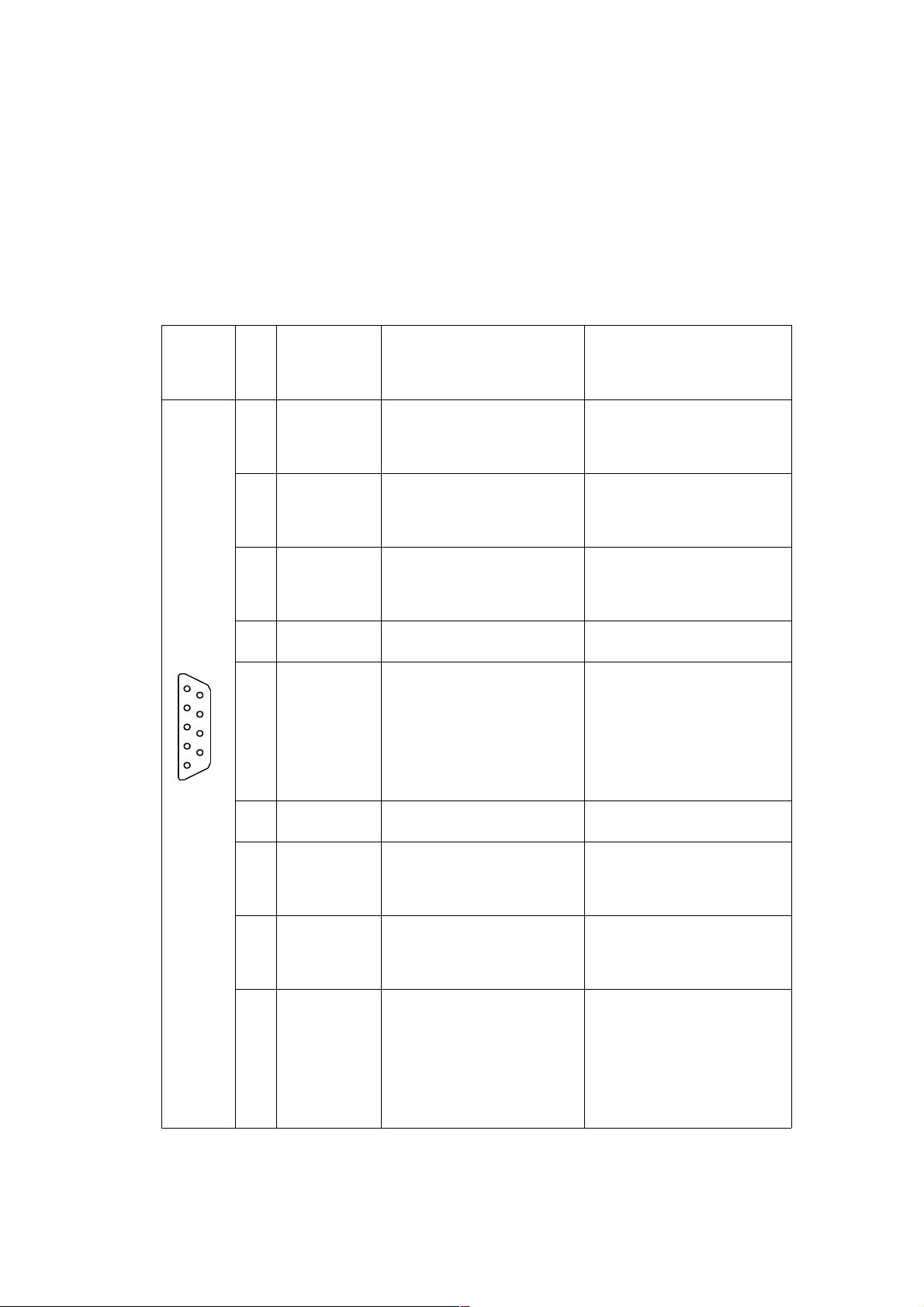
10.5 Bus Plug
For installing the bus cable and the bus interface, 9-channel
D-sub miniature plugs and sockets are used. The pin assignment for the RS485 connection according to PROFIBUS/MODBUS specification is given in table 10.2.
plug Pin RS485-
notation
meaning
Profibus
meaning
Modbus
1
5
6
9
DB 9
1 Shield, protective
Ground
2 RP, Reserved for
Power
VP, positive 5...24 V
D.C. Power Supply
3 RxD/TxD-P, Receive /
Transmit Data-P
PMC, Port Mode Con-
trol
4 CNTR-P, Control-P
5 B / B´ DGND, Data Ground B/B´, transceiver ter-
minal 1, V1 voltage
( V1 > V0 für binary 1
[OFF state] )
6 VP, Voltage Plus
7 RP, Reserved for
Power
8 C / C´ RxD/TxD-P, Receive /
Transmit Data-N
C/C´, signal and power
supply common
9 A / A´ CNTR-N, Control-N A/A´ transceiver termin-
al 0, V0 voltage
( V0 > V1 for binary 0
[ON state] )
Table 10.2 Pin assignment D-sub miniature plug according to PROFIBUS /
MODBUS
Hardware Manual COMBILOG 1022
92
Page 93

Only signal leads A and B (and Shield) are absolutely obligatory for a (shielded) connection. All others can be installed together with these signal leads if required.
10.6 Bus Termination
In order to avoid signal reflections on the bus, each bus segment has to be blanked off at its physical beginning and at its
end with the characteristic impedance. For this purpose, a terminating resistor Rt is installed between the bus leads A and B.
In addition to that the bus lead A is connected via a pull-down
resistor Rd to ground (Data Ground) and the bus lead B is connected via a pull-up resistor Ru to potential (VP). These resistors provide a defined quiescent potential in case there is no
data transmission on the bus. This quiescent potential is level
high.
Figure 10.5 Bus termination
Note: The numbers in brackets in figure 10.5 indicate the pin
number for the connection via the 9-channel D-sub miniature
plug.
Hardware Manual COMBILOG 1022
VP
DGND
Ru
Rt
Rd
VP = +5V
Ru = 390
Ω
± 2%, min ¼ Watt
Rd = 390
Ω
± 2%, min ¼ Watt
Rt = 390
Ω
± 2%, min ¼ Watt
B
A
B (3)
A (8)
Profibus-
Bezeichnung
CombilogKlemmen-
bezeichnung
watt
watt
watt
reference
reference
93
Page 94

The bus termination can be carried out in various ways.
It can either be carried out via external resistors and a separate
power supply, independent of the module, according to figure
10.5. In this case we recommend to use the indicated resistors
for the bus termination.
Or the bus termination is connected with the bus users at the
beginning and at the end of a bus line. Most of the RS485 connections for controls, computers, repeaters, interface converters, etc. offer this option.
Also with data logger COMBILOG 1022 this option is given. Via
the bus termination plug which is available as accessory and
installed at the right or left port on the front side of the device,
the bus termination at this module can be additionally connected. Two jumpers which connect the bus with the bus termination in the data logger are integrated in the bus termination
plug.
Figure 10.6 Bus termination on the COMBILOG 1022
Note: Instead of the bus termination module separate jumpers
can also be used for the bus termination. In this case, please
Hardware Manual COMBILOG 1022
VP
DGND
Ru
Rt
Rd
A
B
94
Page 95

make absolutely sure that the jumper clips are installed as indicated, and that the bus leads or the bus termination are not
short-circuited by mistake!
10.7 Shielding
In case of increased interference we recommend to use shielded bus cables. In this case, a shielding should also be carried
out for the cables from power supply and for the signal cables.
There are varying experiences and recommendations concerning the kind of shield connection. In general the shield should
be connected with the protector ground (not data ground!) at
each bus connection. If necessary the shield should be earthed
additionally several times along the course of the cable. With
smaller distances, e.g. with stub cables, the immunity from
noise often is improved if the shield is only applied to the stub
cable exit.
Figure 10.7 Earthing of the bus line shield on the COMBILOG 1022
Hardware Manual COMBILOG 1022
Isolierung
Schirmgeflechtzentrale Erdung
Central earth in point
braided shield
isolation
95
Page 96

Bus parties such as controls (PLCs), computers (PCs), repeaters and interface converters, a.s.o., mostly offer the possibility
of applying the shield directly to the appliance or to separate
shield rails. The shield rails offer the advantage of preventing
possible interfering signals from being led to the appliance via
the shield. These are already branched off before via the protector ground.
The COMBILOG housing has no direct shield terminals. The
shield of the bus cable can be earthed e.g. by so-called shield
clamps.
Note: The shield must not be connected to bus interfaces
A or B!
Note: The shield should always be connected to earth in a
large surface, low-inductive manner.
10.8 PC Bus Connection
The bus interface of the data logger is based on the RS485
standard. Since most of the hosts are "only" equipped with
RS232 interfaces, an interface converter or a plug-in board with
RS485 drivers is required for conversion purposes.
Theodor Friedrichs offers a compact interface converter.
Furthermore a repeater module is available from
Theodor Friedrichs. This module can be used as a repeater or
as a converter. It also enables to connect the necessary bus
termination with a switch. The repeater/converter has a snapon mounting for installation on standard profile rails (DIN rail)
35 mm (1.4 inch) according to DIN EN 50022.
Hardware Manual COMBILOG 1022
96
Page 97

10.9 Potential Equalization
The difference between the actual physical voltage potentials
DGND of all connections with the bus must not exceed ±7 Volt.
If this cannot be guaranteed, an equalization has to be
provided. For most of the connections this means that the
minus connection of the power supply has to be fed-through as
a compensating line from connection to connection.
10.10 Adjustment of Address and Baud Rate
Before a control unit (PLC) or a computer (PC) can interchange
data with a data logger via the bus, address and baud rate for
the data logger have to be defined. Following hints have to be
considered:
All devices have to be adjusted to the same baud rate.
Within the bus topology the same address must not ap-
pear twice.
bus parameter ASCII-protocol /
MODBUS-Protocol
PROFIBUS-protocol
address 1 ..... 127 1 ..... 126
2,400 bps -
baud rate 4,800 bps -
9,600 bps 9,600 bps
19,200 bps 19,200 bps
38,400 bps -
Table 10.3 Setting variants for address and baud rate
for the data logger COMBILOG 1022
Hardware Manual COMBILOG 1022
97
Page 98

If no other specifications are made on delivery, the data logger
has address 1 and baud rate 19,200 bps, no parity as default.
The adjustment can be changed via bus by means of the configuration software COMBILOG.EXE:
Adjustment via bus by means of the configuration soft-
ware:
The condition for adjusting address and baud rate via bus is
that there are no different data loggers with the same address
on the bus. Otherwise the bus connection has to be disconnected or the supply voltage has to be interrupted for the duration
of the adjustment with those data loggers having the same address as the data logger that is to be newly adjusted. The data
logger to be newly adjusted does not necessarily have to be
set to the same baud rate as the PC, as the adjustment procedure is accomplished as described below:
The adjustment or modification of address and baud rate via
bus is always carried out together with the loading of a
new configuration by means of the configuration software
COMBILOG.EXE. The download is carried out as described in
the online help for the configuration software. The LEDs at the
front indicate which data logger is being newly adjusted at the
moment. If the LED ERR changes from "off" to "flash", a new
program is just being transmitted to the data logger. The values
are taken over as soon as the data transmission via bus has
been successfully completed.
Note: The address “0” is reserved for transmission via
PROFIBUS. This address can therefore not be assigned to a
logger.
Hardware Manual COMBILOG 1022
98
Page 99

Note: The address “127” is reserved for broadcast transmis-
sion in the PROFIBUS-protocol (Level 2) and may only be assigned for these cases.
Adjustment via Interface, RS232 by means of the configur-
ation software:
In addition to the bus interface RS485, the data logger
COMBILOG 1022 has an RS232 computer interface. By means
of the configuration software COMBILOG.EXE addresses can
be assigned and bus parameters can be adjusted via the
RS232 interface similarly as when using the RS485 interface.
Hardware Manual COMBILOG 1022
99
Page 100

11 COMMUNICATION
11.1 Bus Interface
The bus interface of the data logger is an RS485 interface according to the specifications of the EIA-RS485 USA standard.
The host interface is an RS232 interface according to the specifications of the EIA-RS232.
11.2 Bus Protocol
The following protocols are available for the data logger
COMBILOG 1022:
ASCII-protocol
PROFIBUS-protocol (Level 2) according to
DIN 19245, part 1
MODBUS-RTU-protocol according to
PI-MBUS-300 Rev. D
The ASCII protocol can be operated simultaneously with the
PROFIBUS or the MODBUS protocol. The binary protocols
PROFIBUS and MODBUS can only be used exclusively. You
can select the desired binary protocol through a web page.
The ASCII protocol and the PROFIBUS protocol will be delivered as standard.
Hardware Manual COMBILOG 1022
100
 Loading...