

Page 1
CNR 4
Net Radiometer
Instruction Manual
Page 2
1
IMPORTANT USER INFORMATION
Reading this entire manual is recommended for full understanding of the use of this product.
The exclamation mark within an equilateral triangle is intended to alert the user to the presence of important
operating and maintenance instructions in the literature accompanying the instrument.
Should you have any comments on this manual we will be pleased to receive them at:
Kipp & Zonen B.V.
Delftechpark 36
2628 XH Delft
P.O. Box 507
2600 AM Delft
The Netherlands
+31 15 2755 210
info@kippzonen.com
www.kippzonen.com
Kipp & Zonen reserve the right to make changes to the specifications without prior notice.
WARRANTY AND LIABILITY
Kipp & Zonen guarantees that the product delivered has been thoroughly tested to ensure that it meets its published
specifications. The warranty included in the conditions of delivery is valid only if the product has been installed and
used according to the instructions supplied by Kipp & Zonen.
Kipp & Zonen shall in no event be liable for incidental or consequential damages, including without limitation, lost
profits, loss of income, loss of business opportunities, loss of use and other related exposures, however caused,
arising from the faulty and incorrect use of the product.
User made modifications can affect the validity of the CE declaration.
COPYRIGHT
©
2014 KIPP & ZONEN
All rights reserved. No part of this publication may be reproduced, stored in a retrieval system or transmitted in any
form or by any means, without permission in written form from the company.
Manual version: 1409
Page 3
2
DECLARATION OF CONFORMITY
According to EC guideline 89/336/EEC 73/23/EEC
We: Kipp & Zonen B.V.
Delftechpark 36
2628 XH Delft
The Netherlands
Declare under our sole responsibility that the product
Type: CNR 4
Name: Net Radiometer
And
Type: CNF 4
Name: Ventilation Unit
To which this declaration relates is in conformity with the following standards
Imissions EN 50082-1 Group standard
Emissions EN 50081-1 Group standard
EN 55022
Safety standard IEC 1010-1
Following the provisions of the directive
Page 4

3
CONTENTS
IMPORTANT USER INFORMATION ................................................................................................................................... 1!
DECLARATION OF CONFORMITY ..................................................................................................................................... 2!
CONTENTS ................................................................................................................................................................................. 3!
1! GENERAL INFORMATION ............................................................................................................................................ 4!
1.1! Connecting the CNR 4 ............................................................................................................ 5!
1.1.1! The difference between temperature and sensor connection ........................................... 5!
1.1.2! The radiometer Sensor connector (S) ............................................................................... 5!
1.1.3! The radiometer Temperature connector (T) ..................................................................... 7!
1.1.4! The (optional) CNF 4 connector ....................................................................................... 8!
1.1.5! Using the CNR 4 calibration factors ................................................................................. 8!
1.1.6! Using the CNR 4 measuring Net Radiation ....................................................................... 9!
1.1.6.1! Measuring Solar radiation with the pyranometer ........................................................................... 9!
1.1.6.2! Measuring Far Infrared radiation with the pyrgeometer ................................................................ 9!
1.1.6.3! Measuring the CNR 4's body temperature ..................................................................................... 9!
1.1.6.4! Calculation of the albedo for solar radiation ............................................................................... 12!
1.1.6.5! Calculation of the Net Solar radiation ......................................................................................... 12!
1.1.6.6! Calculation of the Net (total) radiation ........................................................................................ 13!
2! CNR 4 PROPERTIES ..................................................................................................................................................... 16!
2.1! Properties of the CNR 4 Net-Radiometer ............................................................................... 16!
2.1.1! Specifications of the CNR 4 ........................................................................................... 17!
2.2! Properties of the pyranometer .............................................................................................. 17!
2.2.1! Specifications of the pyranometer ................................................................................. 18!
2.2.2! Spectral properties of the pyranometer ......................................................................... 20!
2.2.3! Directional / Cosine response of the pyranometer ......................................................... 20!
2.3! Properties of the pyrgeometer .............................................................................................. 22!
2.3.1! Window heating offset .................................................................................................. 22!
2.3.2! Water deposition on the pyrgeometer window ............................................................... 22!
2.3.3! Specifications of the Pyrgeometer ................................................................................. 22!
2.3.4! Spectral properties of the pyrgeometer ......................................................................... 24!
2.3.5! Directional / Cosine response of the pyrgeometer ......................................................... 24!
2.4! Properties of the CNF 4 (optional) ventilation unit ................................................................ 25!
2.4.1! CNF 4 specifications ...................................................................................................... 25!
2.5! Properties of the Pt-100 and thermistor ................................................................................ 26!
3! CALIBRATION ................................................................................................................................................................ 27!
3.1! Calibration of the pyranometers ........................................................................................... 27!
3.2! Calibration of the pyrgeometers ........................................................................................... 27!
3.3! Recalibration of pyranometers and pyrgeometers ................................................................. 27!
3.4! Checking the Pt-100 and Thermistor .................................................................................... 27!
4! INSTALLATION AND MAINTENANCE ................................................................................................................... 28!
4.1! Replacing the drying cartridge ............................................................................................. 28!
4.2! Replacing the Ventilator Filter .............................................................................................. 29!
5! TROUBLE SHOOTING .................................................................................................................................................. 30!
5.1! Testing the pyranometer ...................................................................................................... 30!
5.2! Testing of the pyrgeometer .................................................................................................. 30!
5.3! Testing the Pt-100 ................................................................................................................ 31!
5.4! Testing the thermistor ......................................................................................................... 31!
5.5! Testing the Heater ............................................................................................................... 31!
5.6! Testing the Ventilator .......................................................................................................... 31!
6! CMB 1 OPTIONAL MOUNTING BRACKET ........................................................................................................... 32!
7! DELIVERY ........................................................................................................................................................................ 34!
8! RECALIBRATION SERVICE ......................................................................................................................................... 35!
Page 5

4
1 GENERAL INFORMATION
The CNR 4 is a 4 component net radiometer that measures the energy balance between incoming short-wave
and long-wave Far Infrared (FIR) radiation versus surface-reflected short-wave and outgoing long-wave radiation.
The CNR 4 net radiometer consists of a pyranometer pair, one facing upward, the other facing downward, and a
pyrgeometer pair in a similar configuration. The pyranometer pair measures the short-wave radiation. And the
pyrgeometer pair measures long-wave radiation. The upper long-wave detector of CNR 4 has a meniscus dome. This
ensures that water droplets role off easily and improves the field of view to nearly 180°, compared with a 150° for a
flat window. All 4 sensors are integrated directly into the instrument body, instead of separate modules
mounted onto the housing. Each sensor is calibrated individually for optimal accuracy.
Two temperature sensors, a Pt-100 and Thermistor, are integrated for compatibility with every data logger. The
temperature sensor is used to provide information to correct the infrared readings for the temperature of the
instrument housing. Care has been taken to place the long-wave sensors close to each other and close to the
temperature sensors. This assures that the temperatures of the measurement surfaces are the same and accurately
known. This improves the quality of the long-wave measurements.
The design is very light in weight and has an integrated sun shield that reduces thermal effects on both long-wave
and short-wave measurements. The cables are yellow with waterproof connectors as used with all our new
radiometers. The mounting rod can be unscrewed for transport, like the CNR 2.
An optional ventilation unit with heater is designed as an extension of the sunshield and can be fitted new to the
CNR 4 or retro-fitted later. The ventilation unit CNF 4 is compact and provides efficient air-flow over the domes and
windows to minimize the formation of dew and reduce the frequency of cleaning. The integrated heater can be used
to melt frost.
The CNR 4 specifications when used with CNF 4 comply with the WMO classification of Good Quality
The Net Radiometer, CNR 4, is intended for the analysis of the radiation balance of Solar and Far Infrared radiation.
The most common application is the measurement of Net (total) Radiation at the earth's surface.
The CNR 4 design is such that both the upward facing and the downward-facing instruments measure the energy
that is received from the whole hemisphere (180 degrees field of view). The output is expressed in Watts per square
meter. The total spectral range that is measured is roughly from 0.3 to 42 micrometers. This spectral range covers
both the Solar Radiation, 0.3 to 3 micrometers, and the Far Infrared radiation, 4.5 to 42 micrometers.
Chapter 1 describes how to operate the CNR 4, giving separate attention to the use of the individual pyranometers
and pyrgeometers. More about the physics of the pyranometer and pyrgeometer can be found in chapter 2.
The CNR 4 radiometers all have individual calibration factors. As opposed to the CNR 1 they are not made equal.
The advantage is that the individual sensitivities are more accurate then when made equal with shunt and series
resistors.
For quality assurance of the measurement data, we recommend the recalibration of the CNR 4 as part of a regular
maintenance schedule every two years. More about calibration can be found in chapter 3.
The CNR 4 is intended for continuous outdoor use. It is weatherproof. The materials used in Pyranometer and
pyrgeometer are robust. Contrary to most competitive instruments, plastic domes are not used. Therefore the CNR
4 requires very low maintenance. For optimal results however, proper care must be taken. More about maintenance
can be found in chapter 4. Chapter 5 can be consulted if a problem with the CNR 4 is suspected; this chapter
addresses trouble shooting.
The general user should read chapter 1 and chapter 4.
Page 6
5
1.1 Connecting the CNR 4
1.1.1 The difference between temperature and sensor connection
CNR 4 has several output signals: two voltages for the pyranometers, two voltages for the pyrgeometers, and two
temperature sensors as standard: a 4 wire Pt-100 connection and a 2 wire connection for the 10k thermistor.
Depending on the used data logger one of the temperature sensors can be used.
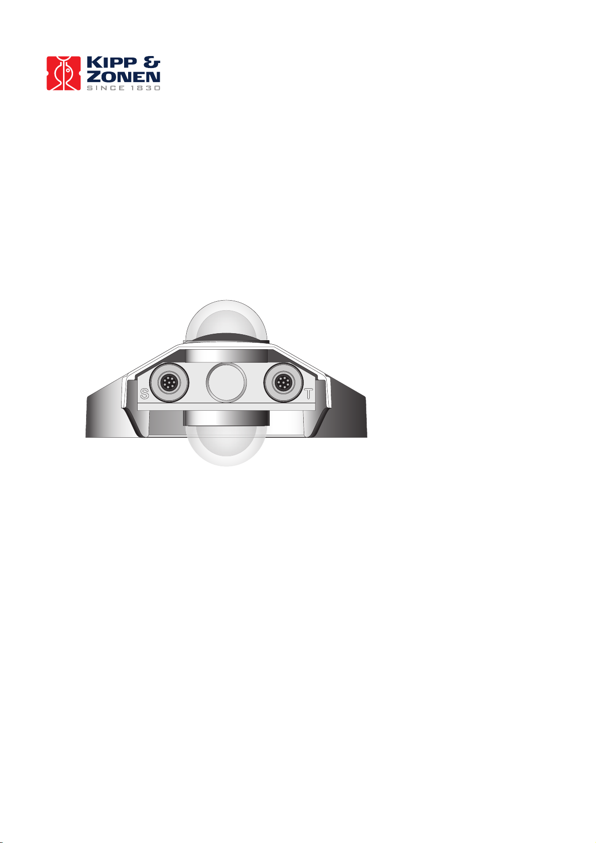
The connector with the 4 sensor outputs is indicated with an S on the back of the CNR 4, the temperature connector
is indicated with a T. The sensor connector has 8 pins and 8 wires are coming out of the cable on the other end.
The Temperature connector has also 8 pins but only 6 wires are coming out of the cable.
Exchanging the connectors will not damage the CNR 4. To prevent mix up of the cables after installation it is
advised to mark the cables with a permanent marker or tape showing also S and T.
Figure 1.1 Back of the CNR 4 with the connector for sensor outputs on the left, the temperature connector on the
right and mounting rod in the middle.
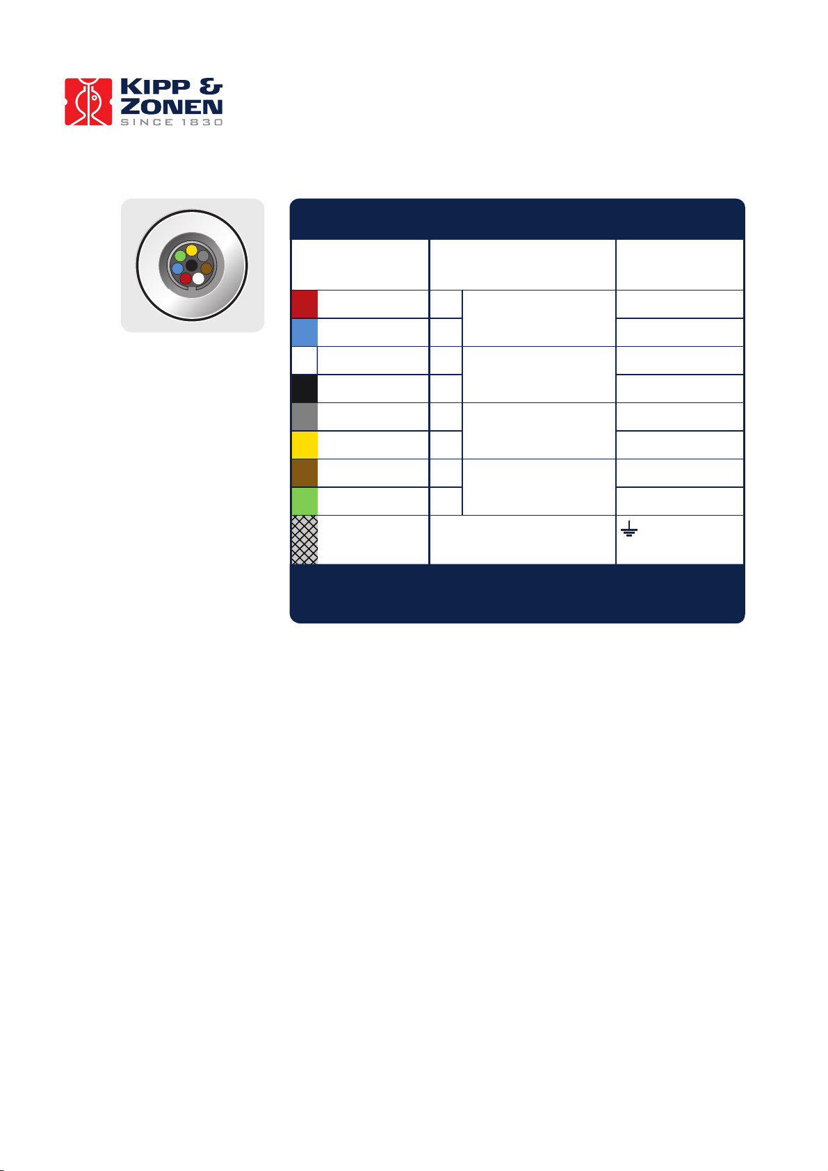
1.1.2 The radiometer Sensor connector (S)
CNR 4 sensor connector carries the signals for the two pyranometers and two pyrgeometers. The pin numbers and
wire colours are indicated in the diagram below. The shield of the cable is twisted together and covered with a black
sleeve. If the CNR 4 (rod) is grounded to the mast it is advised not to connect the shielding on the data logger side.
This might cause ground loops and offsets in the signal.
Page 7
6
Figure 1.2 The sensor connections of the CNR 4. The sensor has four mV outputs, 2 for the pyranometers and 2 for
the pyrgeometers
Ground *
Erde
Terre
Tierra
Red
Rot • Rouge • Rojo
Wire
Kabel
Fil
Cable
White
Weiss • Blanc • Blanco
Brown
Braun • Brun • Marrón
Black
Schwarz • Noir • Negro
Grey
Grau • Gris • Gris
Function
Funktion
Fonction
Función
Pyranometer Upper
Oben • Supérieur • Superior
Pyranometer Lower
Unten • Inférieur • Más bajo
Pyrgeometer Upper
Oben • Supérieur • Superior
Pyrgeometer Lower
Unten • Inférieur • Más bajo
Blue
Blau • Bleu • Azul
Connect with
Anschluss an
Relier à
Conectar con
Yellow
Gelb • Jaune • Amarillo
Green
Grün • Vert • Verde
Housing
Gehäuse
Boîte
Cubierta
Shield
Abschirmung
Protection
Malla
+ Hi
+ Hi
+ Hi
+ Hi
-
Lo
-
Lo
CNR 4 NET RADIOMETER • SENSOR
8 WIRE CABLE • 8-ADRIGES KABEL • CÂBLE 8 FILS • CABLE DE 8 CONDUCTORES
-
Lo
-
Lo
+
-
-
-
-
+
+
+
* Connect to ground if radiometer not grounded
Mit Erde verbinden, wenn das Radiometer nicht geerdet ist
Reliez à la terre si le radiomètre n'est pas connecté
Conectar a tierra si el radiómetro no lo está
1
2
345
6
7
8
1
2
7
8
5
4
6
3
Page 8
7
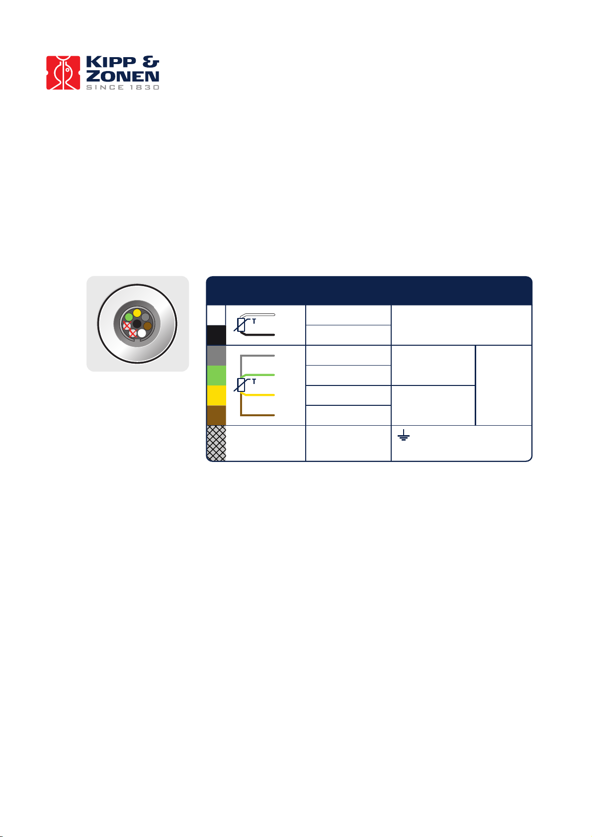
1.1.3 The radiometer Temperature connector (T)
The temperature connector of the CNR 4 carries the signals for the PT-100 and Thermistor. The PT-100 and
Thermistor have identical accuracy, the reason for selecting one or the other is mainly the data logger involved. The
Pt-100 temperature sensor has 4 wires, two for the measuring current and two for measuring the voltage over the
resistor (100 Ohm @ 0 °C) . In this way the measurement accuracy is minimally affected by the cable length. The
thermistor has a higher impedance of 10 kOhm and is therefore less influenced by cable length but has no
compensation for it. The shield of the cable is twisted together and covered with a black sleeve. If the CNR 4 (rod)
is grounded to the mast it is advised not to connect the shielding on the data logger side. This might cause ground
loops and offsets in the signal.
Figure 1.3 The temperature connections of the CNR 4. The instrument has one (4-wire) Pt-100 output and a
Thermistor with a 2-wire connection.
CNR 4 NET RADIOMETER • TEMPERATURE
6 WIRE CABLE • 6-ADRIGES KABEL • CÂBLE 6 FILS • CABLE DE 6 CONDUCTORES
7
8
5
3
4
6
Grey
Grau • Gris • Gris
Combined
Kombiniert
Combiné
Combinado
Pt-100
Standard
Standard
Etalon
Estándar
Combined
Kombiniert
Combiné
Combinado
Brown
Braun • Brun • Marrón
Green
Grün • Vert • Verde
Yellow
Gelb • Jaune • Amarillo
White
Weiss • Blanc • Blanco
Thermistor
Standard
Standard
Etalon
Estándar
Black
Schwarz • Noir • Negro
1
2
345
6
7
8
Ground *
Erde
Terre
Tierra
Housing
Gehäuse
Boîte
Cubierta
Shield
Abschirmung
Protection
Malla
Page 9
8
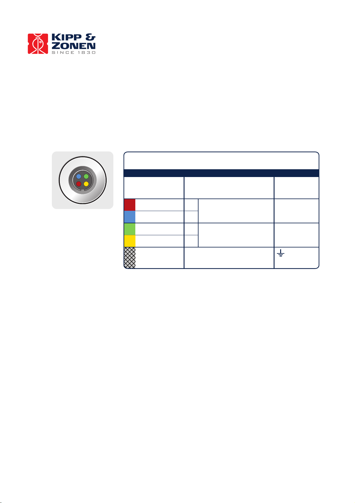
1.1.4 The (optional) CNF 4 connector
The optional ventilator CNF 4 for the CNR 1 has separate wires for heating and ventilation. In case the heater is
used also the ventilator should be active. The other way around the ventilator can be used without heating. When
the ventilation unit is mounted later on the CNR 4, the extra bottom plate mounts to the bottom of the CNR 4. The
(S) and (T) cables run on both sides of the ventilator to the back of the CNF 4 housing. The extra cover that comes
with the CNF 4 slides under the CNR 4 cover. The 4 pins connector on the back of the CNF 4 is shown below. The
CNR 4 without CNF 4 is supplied with an extra serial number label. This can be used to put on the bottom of the
CNF 4 when mounted (later) on the CNR 4.
Figure 1.3 The heater and ventilator connections of the CNF 4.
1.1.5 Using the CNR 4 calibration factors
The pyranometer generates a mV signal that is simply proportional to the incoming solar Radiation. The conversion
factor between voltage, V, and Watts per square metre of solar irradiance E, is the so-called calibration constant C
(or sensitivity).
For each pyranometer E = V/C (1.1)
When using the pyrgeometer, you should realise that the signal that is generated by the pyrgeometer represents the
exchange of Far Infrared (thermal) radiation between the pyrgeometer and the object that it is facing. This implies
that the pyrgeometer will generate a positive voltage output, V, when it faces an object that is hotter than its own
sensor housing, and that it will give a negative voltage signal when it faces an object that is colder. This means that
for estimating the Far Infrared radiation that is generated by the object that is faced by the pyrgeometer, usually the
sky or the soil, you will have to take the pyrgeometer temperature, T, into account. This is why a the temperature
sensors are incorporated in the CNR 4's body near the pyrgeometer sensing element, and has therefore the same
temperature as the pyrgeometer sensor surface. The calculation of the Far Infrared irradiance, E, is done according
to the following equation:
For the pyrgeometer only E = V/C + 5.67⋅10-8*T4 (1.2)
In this equation C is the sensitivity of the sensor. Please bear in mind that T is in Kelvin, and not in Celsius or
Fahrenheit.
Red
Rot • Rouge • Rojo
Wire
Kabel
Fil
Cable
Green
Grün • Vert • Verde
Yellow
Gelb • Jaune • Amarillo
Function
Funktion
Fonction
Función
5 Watt ventilator 12 VDC
Ventilator • Ventilateur • Ventilador
10 Watt heater 12 VDC
Heizung • Chauffage • Calentador
Blue
Blau • Bleu • Azul
Connect with
Anschluss an
Relier à
Conectar con
+
-
-
+
2
4
1
3
CNF 4 VENTILATION UNIT
(OPTIONAL • OPTION • OPTION • OPCIONAL)
4 WIRE CABLE • 4-ADRIGES KABEL • CÂBLE 4 FILS • CABLE DE 4 CONDUCTORES
Ground *
Erde
Terre
Tierra
Housing
Gehäuse
Boîte
Cubierta
Shield
Abschirmung
Protection
Malla
1
2
3
4
Page 10

9
1.1.6 Using the CNR 4 measuring Net Radiation
In the CNR 4 all components are measured separately. This implies that you should connect all individual
radiometers and one of the temperature sensors. The two pyranometers will measure the solar radiation, both
incoming and reflected, the two pyrgeometers will measure the Far Infrared radiation. For proper analysis of the
pyrgeometer measurement results, they must be temperature corrected using the temperature measurement. The
following paragraphs describe how you should treat the instrument, and how different parameters like net Solar
radiation, net Far Infrared radiation, soil temperature, sky temperature, and Net (total) radiation can be calculated.
Because all radiometers have different sensitivities it is not possible to interconnect the outputs to get the total Net
Radiation.
1.1.6.1 Measuring Solar radiation with the pyranometer
Measuring with a pyranometer can be done by connecting two pyranometer wires, + and -, to a voltmeter. Incidental
light results in a positive signal. The pyranometer mounting plate and ambient air should be at the same
temperature, as much as possible. Conversion of the voltage to irradiance can be done according to equation 1.1.
This is sometimes done in the data logging system itself, sometimes during evaluation in the user's software.
Measuring with the upward-facing pyranometer, the so-called global (solar) radiation is measured. The downwardfacing pyranometer measures the reflected solar radiation. When calculating the Net radiation, the Reflected
radiation must be subtracted from the global radiation. See 1.1.6.5.
1.1.6.2 Measuring Far Infrared radiation with the pyrgeometer
A measurement with the pyrgeometer can be performed by connecting two pyrgeometer wires, + and -, to a voltmeter. A signal radiating from a source which is warmer than the pyrgeometer results in a positive signal.
To measure the Far Infrared irradiances with the two pyrgeometers, separately the Pt-100 output is required. The
formula 1.2 is used to calculate the Far Infrared irradiance of the sky and of the ground.
With the downward-facing pyrgeometer, you would generally measure the Far Infrared radiation that is emitted by
the ground. In contrast, the upward-facing pyrgeometer is generally used to measure the Far Infrared radiation from
the sky. As the sky is typically colder than the instrument, you can expect negative voltage signals from the upwardfacing pyrgeometer.
1.1.6.3 Measuring the CNR 4's body temperature
The CNR 4 has two temperature sensors built in as standard. The main reason to choose between the Pt-100 or the
Thermistor is the connected data logger.
Some data loggers have inputs for thermistors some only for thermistors some have both.
Check carefully the correct sensor regarding to the data logger. There is no difference in accuracy.
The Pt-100 however can be used in 4 wire mode as is therefore compensated for longer wires.
The Thermistor has itself higher impedance (10k) and is less susceptible for longer wires, but can not be
compensated for it.
To obtain a signal from the Pt-100, a current of about 1 mA is fed through two wires on either side of the PT-100.
The voltage that is generated must be measured using the other pair of wires which are connected in parallel with
the PT-100.This is known as a 4-wire measurement. Measuring in this manner eliminates errors during measurement, which would be produced by additional wire length. Some systems have a 3-wire connection. In this case omit
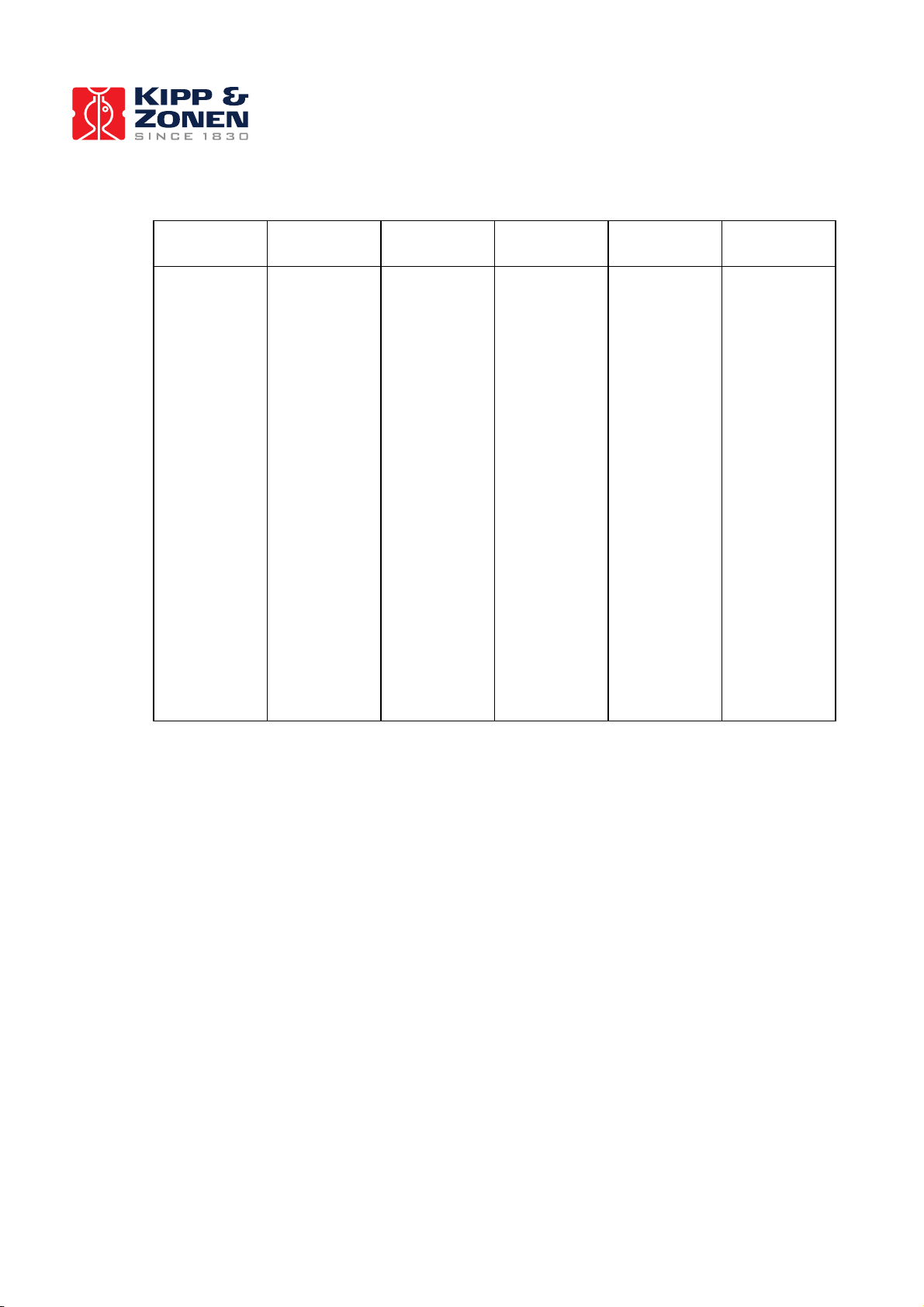
one current lead and follow the instructions of your measurement system manual. Table 1.1 states the Pt-100
resistance values as a function of temperature. Please note that for use in formula 1.2, you must use Kelvin, not
degrees Celsius or Fahrenheit. Most data acquisition systems have standard readout and conversion for Pt-100's. .
The thermistor resistance values as a function of temperature are indicated in table 1.2.
Page 11
10
Temperature
[EC]
Resistance
[Ω]
Temperature
[EC]
Resistance
[Ω]
Temperature
[EC]
Resistance
[Ω]
-30
-29
-28
-27
-26
-25
-24
-23
-22
-21
-20
-19
-18
-17
-16
-15
-14
-13
-12
-11
-10
-9
-8
-7
-6
-5
-4
-3
-2
-1
88.22
88.62
89.01
89.40
89.80
90.19
90.59
90.98
91.37
91.77
92.16
92.55
92.95
93.34
93.73
94.12
94.52
94.91
95.30
95.69
96.09
96.48
96.87
97.26
97.65
98.04
98.44
98.83
99.22
99.61
0
1
2
3
4
5
6
7
8
9
10
11
12
13
14
15
16
17
18
19
20
21
22
23
24
25
26
27
28
29
100.00
100.39
100.78
101.17
101.56
101.95
102.34
102.73
103.12
103.51
103.90
104.29
104.68
105.07
105.46
105.85
106.24
106.63
107.02
107.40
107.79
108.18
108.57
108.96
109.35
109.73
110.12
110.51
110.90
111.28
30
31
32
33
34
35
36
37
38
39
40
41
42
43
44
45
46
47
48
49
50
51
52
53
54
55
56
57
58
59
111.67
112.06
112.45
112.83
113.22
113.61
113.99
114.38
114.77
115.15
115.54
115.93
116.31
116.70
117.08
117.47
117.85
118.24
118.62
119.01
119.40
119.78
120.16
120.55
120.93
121.32
121.70
122.09
122.47
122.86
Table 1.1 Resistance values versus temperature in °C of the CNR 4's Pt-100.
The Pt-100 complies with the class A specifications of DIN.
Page 12
11
Temperature
[EC]
Resistance
[Ω]
Temperature
[EC]
Resistance
[Ω]
Temperature
[EC]
Resistance
[Ω]
-30
-29
-28
-27
-26
-25
-24
-23
-22
-21
-20
-19
-18
-17
-16
-15
-14
-13
-12
-11
-10
-9
-8
-7
-6
-5
-4
-3
-2
-1
135200
127900
121100
114600
108600
102900
97490
92430
87660
83160
78910
74910
71130
67570
64200
61020
58010
55170
52480
49940
47540
45270
43110
41070
39140
37310
35570
33930
32370
30890
0
1
2
3
4
5
6
7
8
9
10
11
12
13
14
15
16
17
18
19
20
21
22
23
24
25
26
27
28
29
29490
28150
26890
25690
24550
23460
22430
21450
20520
19630
18790
17980
17220
16490
15790
15130
14500
13900
13330
12790
12260
11770
11290
10840
10410
10000
9605
9227
8867
8523
30
31
32
33
34
35
36
37
38
39
40
41
42
43
44
45
46
47
48
49
50
51
52
53
54
55
56
57
58
59
8194
7880
7579
7291
7016
6752
6500
6258
6026
5805
5592
5389
5193
5006
4827
4655
4489
4331
4179
4033
3893
3758
3629
3504
3385
3270
3160
3054
2952
2854
Table 1.2 Resistance values versus temperature in °C of the CNR 4's thermistor.
Relatively small errors occur when the CNR 4 is not in thermal equilibrium. This happens for example when the
heater is on, or when the sun is shining. When the heater and ventilator are on, the largest expected deviation
between real sensor temperature and Pt-100 or thermistor reading is less than 0.5 degree.
The internal temperature sensors will not give a good indication of ambient air temperature; at 1000 Watts per
square meter Solar Radiation, and no wind, the instrument temperature can rise a few degrees above ambient
temperature. This will not affect the readings of the CNR 4
The offsets of both pyranometers and pyrgeometers might be larger than 5 Watts per square meter if large
temperature gradients are forced on the instrument (larger than 5 K/hr). This happens for example when rain hits
the instrument. The occurrence of this can be detected using the temperature sensor readout. It can be used as a
tool for quality assurance of your data.
Page 13

12
1.1.6.4 Calculation of the albedo for solar radiation
The albedo is the ratio of incoming and reflected Solar radiation. It is a figure somewhere between 0 and 1. Typical
values are 0.9 for snow, and 0.3 for grassland. To determine albedo, the measured values of the two pyranometers
can be used. The pyrgeometers are not involved, as they do not measure Solar radiation. Do not use measured
values when solar elevation is lower than 10 degrees above the horizon. Errors in measurement at these elevations
are likely and thus yielding unreliable results. This is due to deviations in the directional response of the
pyranometers.
Albedo = (E lower pyranometer) / (E upper pyranometer) (1.3)
In the above formula, E is calculated according to formula 1.1.
Albedo will always be smaller than 1. Checking this can be used as a tool for quality assurance of your data. If you
know the approximate albedo at your site, the calculation of albedo can also serve as a tool for quality control of
your measured data at this specific site.
1.1.6.5 Calculation of the Net Solar radiation
Net Solar radiation is the incoming Solar Radiation minus the reflected solar radiation. It equals the solar radiation
that is absorbed by the earth's surface.
Net Solar radiation = (E upper pyranometer) - (E lower pyranometer) (1.4)
In this formula E is calculated according to formula 1.1.
Net Solar radiation will always be positive. Checking this can be used as a tool for quality assurance of your
measured data.
Calculation of the Net Far Infrared radiation, soils temperature and sky temperature
Net Far Infrared radiation is, like Net Solar radiation, the part that contributes to heating or cooling of the earth's
surface. In practice most of the time, Net Far Infrared radiation will be negative.
Net Far Infrared radiation = (E upper pyrgeometer) - (E lower pyrgeometer) (1.5)
In this formula E is calculated according to formula 1.2. From this equation the term with T cancels.
The E measured with the pyrgeometer, actually represents the irradiance of the sky (for the upward- facing
pyrgeometer) or the ground (for the downward-facing pyrgeometer). Assuming that these two, ground and sky,
behave like perfect blackbodies (actually this is only in theory), you can calculate an effective "Sky temperature" and
an effective "Ground temperature".
Sky temperature = ((E upper pyrgeometer)/ 5.67⋅10-8)
1/4
(1.6)
Ground temperature = ((E lower pyrgeometer)/ 5.67⋅10-8)
1/4
(1.7)
As a rule of thumb, for ambient temperatures of about 20 degrees Celsius, you can say that one degree of
temperature difference between two objects results in a 5 Watts per square metre exchange of radiative energy
(infinite objects):
1 degree of temperature difference = 5 Watts per square metre (rule of thumb)
Page 14
13
1.1.6.6 Calculation of the Net (total) radiation
The Net radiation, NR, can be calculated using all 4 sensor measurement results:
NR = (E upper pyranometer) + (E upper pyrgeometer) - (E lower pyranometer) - (E lower pyrgeometer)
(1.8)
Where E is the irradiance that is calculated for the pyranometer according to equation 1.1, for the pyrgeometer
according to equation 1.2. the terms with T cancel from this equation.
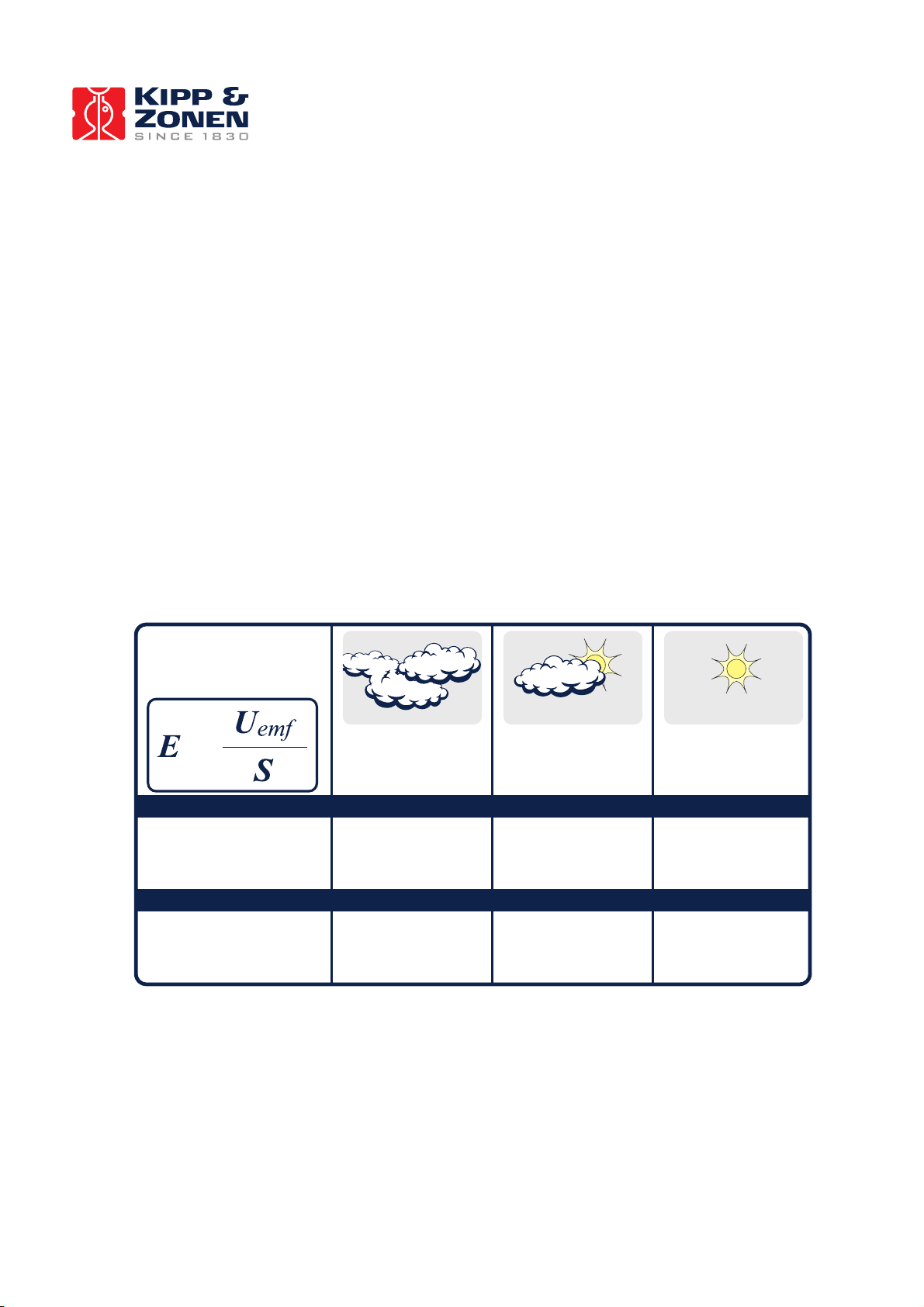
1.2 CNR 4 Performance under different conditions
Below, table 1.3, shows an indication of what you might typically expect to measure under different meteorological
conditions. The first parameter is day and night. At night, the Solar radiation is zero. The second column indicates if
it is cloudy or clear. A cloud acts like a blanket, absorbing part of the Solar radiation, and keeping Net Far Infrared
radiation close to zero. The third parameter is ambient temperature. This is included to show that the "sky
temperature" (column nine) tracks the ambient temperature. Under cloudy conditions this is logical; cloud bases will
be colder than the ambient temperature at instrument level, the temperature difference depends roughly on cloud
altitude.
Under clear sky conditions it is less obvious that sky temperature "adjusts" to the ambient temperature. This can
roughly be attributed to the water vapour in the air, which is a major contributor to the Far Infrared radiation.
Fig. 1.2.1 Different measurement conditions and signals
Fully clouded
Sunny, partly clouded
Clear and Sunny
Values calculated using:
Werte, errechnet aus Formel:
Calcul des valeurs à l'aide:
Utilizar valores calculados:
Upper
Oben • Supérieur • Superior
Lower
50 ... 120 W/m²
0 ... 50 W/m²
120 ... 500 W/m²
50 ... 200 W/m²
500 ... 1000 W/m²
200 ... 400 W/m²
Unten • Inférieur • Más bajo
Bewölkt
Très nuageux
Totalmente Nublado
Sonnig, teils bewölkt
Ensoleillé, un peu nuageux
Parcialmente nublado
Klarer Himmel und sonnig
Clair et ensoleillé
Cielo despejado
=
0 ... -10 W/m²
-25 ... 25 W/m²
-10 ... -50 W/m²
-25 ... 25 W/m²
-50 ... -150 W/m²
-25 ... 25 W/m²
Upper
Oben • Supérieur • Superior
Lower
Unten • Inférieur • Más bajo
Pyranometer
Pyrgeometer
Page 15

14
Typical graphs for the pyrgeometers
Figure 1.2.2 partly clouded day for the upper pyrgeometer
Figure 1.2.3 clear day for the downward facing pyrgeometer
Upper%pyrgeometer,%%day%with%alterna3ng%cloud%fields%%%
%
"#$%&'(&)&$*!!+,&(-!.!/&012342)#!56.(78! 9&("!:/;!<<=>?!5@A8!
Upwelling%signal%(downward%facing)%pyrgeometer%
%
B#$%&'(&)&$*!+C&(-!.!1&012342)#!56.(78!
9&("!'-!201)$D(&0)!5@A8!
Page 16

15
It is assumed that when ambient temperature varies, the Net Far Infrared radiation remains roughly the same,
independent of ambient temperature. The resulting measured values of the pyrgeometer's and pyranometer's are
stated in columns 4 to 7. These are indicative figures only, they depend strongly on other circumstances; the
pyrgeometer results, of course, change with the sensor temperature. This is indicated in column 8. During the day,
the Pt-100 reading may rise due to solar heating, up to 10 degrees above ambient temperature. During the night,
the sensor temperature may be lower than the ambient temperature due to Far Infrared radiative cooling. The latter
two effects do not influence the end result of the calculations of Sky T and ground T. Therefore they are not taken
into account in the table. Actually in column 4 you might expect to see "0 to -50" for all positions that are showing
"0", in column 5 the "0" values may in reality be "-20 to +20". The resulting sky temperature is indicated in column
9. Under cloudy conditions this sky temperature is equal to ambient temperature. Under clear conditions the sky
temperature is lower than the ambient temperature.
The ground temperature in column 10 is assumed to be equal to the ambient temperature. In practice it may be
higher during the day, due to solar heating. Ground temperature may be lower than ambient during the night, due
to Far Infrared radiative cooling. The sky and the ground temperature can be calculated from the measured values
of the sensors using formulas 1.6 and 1.7.
day
night
Cloudy
clear
+20 ºC
- 20 ºC
pyrgeo
Up
pyrgeo
low
pyrano
up
pyrano
low
Pt 100
thermistor
sky T
ground
T
d
cloud
20
0
-20 - 20
0-500
0-150
20
20
20 d cloud
-20
0
-20 - 20
0-500
0-150
-20
-20
-20 d clear
20
-100*
-20 - 20
0-1300
0-400
20
1*
20 d clear
-20
-100*
-20 - 20
0-1300
0-400
-20
-53*
-20 n cloud
20
0
-20 - 20 0 0
20
20
20 n cloud
-20
0
-20 - 20 0 0
-20
-20
-20 n clear
20
-100***
-20 - 20
0** 0 20
1***
20 n clear
-20
-100***
-20 - 20
0** 0 -20
-
53***
-20
Table 1.2.2 Typical output signals of CNR 4 under different meteorological conditions. Explanation can be found in
the text.
* Values may suffer from the so-called window heating offset; the sun heats the pyrgeometer window causing a
measurement error of + 10 Watts per square metre (maximum).
** Values may suffer from negative Infrared offsets, caused by cooling off of the pyranometer dome by Far Infrared
radiation. The maximum expected offset value is 15 Watts per square metre.
*** Values may suffer from dew deposition. This causes the pyrgeometer-up values to rise from -100 to 0 Watts per
square metre.
1.3 Quality assurance of data
Because of the fact that separate sensors are used in the CNR 4, there are possibilities to check the quality of the
data by analysing the signals. For this, you can use the measurement results of the temperature, the albedo and the
net-solar radiation. If the values that are obtained for these quantities exceed certain values, this can be an
indication that something is wrong. For more details we refer to the paragraphs 1.2, table 1.2.1 and 1.2.2.
Page 17

16
2 CNR 4 PROPERTIES
The CNR 4 consists of two pyranometers, for measuring solar radiation, and of two pyrgeometers for measuring Far
Infrared radiation. Two temperature sensors are available as standard, a Pt-100 and thermistor. The optional
ventilation unit CNF 4 is described in chapter 2.5
2.1 Properties of the CNR 4 Net-Radiometer
The properties of CNR 4 are mainly determined by the properties of the individual sensors. Generally the accuracy
of CNR 4 will be higher than that of competitive Net-Radiometers. The main reasons are that the solar radiation
measurement performed by the pyranometer is accurate, and offers a traceable calibration. Also the optionally
integrated ventilation and heating improve the accuracy significantly. Due to the fact that the Net Solar radiation
can be very intense, 1000 Watts per square metre compared to a typical -100 for the Net Far Infrared radiation, the
accuracy of the solar measurement is very critical. Wind corrections, as applied by less accurate competitive
instruments are not necessary. The robustness of the materials used implies that CNR 4 will not suffer from damage
inflicted by birds. Figure 2.1 depicts a drawing of CNR 4. From a spectral point of view, the pyranometer and
pyrgeometer are complementary. Together they cover the full spectral range: The pyranometer from 0.3 to 3
microns, and the pyrgeometer from 4.5 to 42 microns. The gap between these two produces negligible errors.
Figure 2.1 The dimensions of the CNR 4 with CNF 4 ventilation unit, side view
Figure 2.2 The dimensions of the CNR 4 with CNF 4 ventilation unit, top view
405 mm 347 mm
Page 18

17
2.1.1 Specifications of the CNR 4
General specifications
Environmental
0 - 100% RH (Relative Humidity)
Definition
Intended for continuous outdoor use
Bubble level sensitivity
< 0.5º (bubble half inside ring)
General Construction
Sensor
Thermopile
Receiver paint
Carbon Black
Desiccant
Silica gel (replaceable)
Housing materials
Anodized Aluminum body
Cable Connectors
Binder series 712
Cable (2 cables)
Color Yellow, Poly Urethane, Halogen free, UV blocking
Cable length (2 cables)
m
10 (standard), 25, 50 (optional)
Weight
kg
0.85 (without cables)
Shock / vibration
IEC 721-3-2-2m2
Operating temperature
°C
-40 to +80
CE according to EC guideline 89/336/EEC 73/23/EEC
Environmental protection
IP 67
2.2 Properties of the pyranometer
The pyranometer consists of a thermopile sensor and a glass dome both integrated in the CNR 4 body. The
thermopile is coated with a black absorbent coating. The paint absorbs the radiation, and converts it to heat. The
resulting heat flow causes a temperature difference across the thermopile. The thermopile generates a voltage
output. The thermopile and the resistor determine most electrical specifications. The absorber paint and the dome
determine spectral specifications. The thermopile is encapsulated in the housing in such a way that its field of view
is 180 degrees, and that its angular characteristics fulfil the so-called cosine response.
Page 19

18
2.2.1 Specifications of the pyranometer
Pyranometers Specification
Unit
Value (All indicated values are absolute values)
Spectral range
nm
300 - 2800 (50% points)
Definition
Instrument sensitivity within a specific spectral range
Sensitivity
µV/ W/m²
10 to 20
Definition
Calibration factor
Impedance
Ω
20 to 200, typically 50
Definition
Typical resistance measured at the output
Response time
s
< 18 (95% response)
Definition
Sensor response time
Non-linearity
%
< 1 (from 0 to 1000 W/m2 irradiance)
Definition
Maximum deviation from the responsivity at 500 W/m2 due to any
change of irradiance within the indicated range.
Temperature dependence of
sensitivity
%
N/S (- 40 °C to -10°C)
< 4 (- 10 °C to +40 °C)
N/S (+40 ºC to +80 ºC)
Definition
Maximum error due to any change of instrument temperature within
the indicated temperature interval.
Tilt error
%
< 1
Definition
Maximum deviation from the responsivity when tilted at any angle
and at 1000 W/m² irradiance .
Zero offset A
W/m²
< 15 (0 to -200 W/m² / IR net irradiance)
Definition
Caused by cooling of the dome due to sky radiation
Zero offset B
W/m²
< 3 (at 5 K/h temp. change)
< 1 (with CVF 4 installed)
Definition
Response to change in ambient temperature.
Field of view:
Upper detector
Lower detector
180º
150º (due to lower sun shield. To prevent illumination at low zenith
angles)
Definition
Sensor opening angle
Directional error
W/m²
< 20 (angles up to 80° with 1000 W/m² beam radiation)
Definition
Combined zenith and azimuth error from 0°- 80° with 1000 W/m²
beam radiation
Page 20

19
Irradiance:
W/m²
0 to 2000
Definition
Measurement range
Non-stability
%
< 1
Definition
Maximum change of sensitivity per year, percentage of full scale
Spectral selectivity
%
< 3% (350 – 1500 nm spectral interval)
Definition
Deviation of the product of spectral absorption and spectral
transmittance from the corresponding mean within the indicated
spectral range
Uncertainty in daily total
%
< 5 (95 % confidence level)
Definition
Achievable uncertainty
International standards
WMO
ISO
Good quality
First Class
Instrument calibration
Indoors, side by side against reference CMP 3 pyranometer
according to ISO 9847:1992 annex A.3.1
Page 21

20
2.2.2 Spectral properties of the pyranometer
The spectral properties of the pyranometer are mainly determined by the properties of the absorber paint and the
glass dome. These are depicted in figure 2.3
Figure 2.3 The spectral sensitivity of the pyranometer in combination with the spectrum
of the sun, under a clear sky.
2.2.3 Directional / Cosine response of the pyranometer
The measurement of solar radiation falling on a surface (also called irradiance or radiative flux) requires three
assumptions: The surface is spectrally black, i.e. that it absorbs all radiation from all wavelengths. Its field of view is
180 degrees. The directional properties are similar to that of a blackbody. Another way of expressing these
directional properties is to say that the sensor has to comply with the cosine response.
A perfect cosine response will show maximum sensitivity (1) at an angle of incidence of 0E (perpendicular to the
sensor surface) and zero sensitivity at an angle of incidence of 90E (radiation passing over the sensor surface).
Between 90 and 0 degrees, the sensitivity should be proportional to the cosine of the angle of incidence. Figure 2.4
shows the behaviour of a typical pyranometer. The vertical axis shows the deviation from ideal behaviour,
expressed in percentage of the ideal value.
Page 22

21
Figure 2.4 The directional response, or cosine response, of the pyranometer:
On the horizontal axis, the zenith angle is shown (0E zenith angle equals 90E angle of incidence).
The vertical axis shows the deviation from the ideal cosine behaviour expressed in percents.
Page 23

22
2.3 Properties of the pyrgeometer
The pyrgeometer consists of a thermopile sensor and a silicon window integrated in the CNR 4 body. The
thermopile is coated with a black absorbent coating. The paint absorbs the radiation and converts it to heat. The
resulting heat flow is converted to a voltage by the thermopile. Most electrical specifications are determined by the
thermopile and the resistor.
Spectral specifications are determined by the absorber paint and the window. The window serves both as
environmental protection and as a filter. It only transmits the relevant Far Infrared radiation, while obstructing the
Solar radiation. The upper thermopile has a dome shaped window so that its field of view is 180 degrees, and that
its angular characteristics fulfil the so-called cosine response as much as possible, in this field of view. It causes
water droplets to run of more easily.
The field of view of the lower pyrgeometer is 150 degrees. It is limited due to the use of a flat window. This does
not produce a large error because the missing part of the field of view does not contribute significantly to the total,
and is compensated for during calibration.
There is no international standard that classifies pyrgeometers. Pyrgeometers have two specific properties that
deserve special attention. The first is the so-called window-heating offset; the second is the influence of water
deposition on the window.
2.3.1 Window heating offset
The window heating offset is a measurement error that is introduced by the heating of the pyrgeometer window by
the sun. It only occurs during the day. During a sunny day, the upper pyrgeometer will suffer from this. This error
can be reduced by shading or ventilating. On a sunny windless day with a solar irradiance of 1000W/m2, an error of
6 Watts per square meter can be expected. The window will absorb part of the solar radiation and will heat up. As a
result of this heating, heat will irradiate towards the thermopile. This results in an error source, in the Infrared
range. This error is neglected, however, in the net radiation calculation this is justified because the solar radiation is
always dominant when this error occurs. Due to its construction the window heating offset in the CNR 4 is
extremely small compared with other instruments.
2.3.2 Water deposition on the pyrgeometer window
The second specific error source of a pyrgeometer is the substantial measurement error introduced as the result of
water deposition on the window. Water will completely obstruct the transmission of Far Infrared radiation. Water
deposition will occur when it rains, snows, or when dew is deposited.
In the case of rain or snow, the resulting error is not very significant, mainly due to the fact that under these cloudy
conditions, the pyrgeometer signal will be close to zero anyway. The cloud base temperature is generally close to
ambient temperature. The conditions under which dew can form are much more likely to produce significant errors.
A typical situation occurs at night, with a cloudless sky, low wind speeds, and high humidity (so-called clear,
windless nights). Under these conditions, the upward-facing pyrgeometer signal is large, typically -100 Watts per
square metre. When dew occurs, this reading can drop to zero, resulting in a 100 Watts per metre square error.
Generally speaking this kind of error is too large, and if possible it should be avoided. Ventilation and heating can
prevent dew deposition with the CNR 4's optional CNF 4. Heating will keep the instrument window above the dew
point and ventilation will keep the domes clean from rain and snow.
2.3.3 Specifications of the Pyrgeometer
The output of the pyrgeometer is a small voltage, in the mV range. It is proportional to the temperature difference
between the pyrgeometer and the object that it faces. This implies that for calculation of the absolute quantity of
Far Infrared radiation, that is emitted by the sky or the ground you also need to take the pyrgeometer temperature
into account. This temperature is measured by a Pt-100 that is incorporated in the body of CNR 4. The calculation of
the Far Infrared irradiance is described in chapter 1.
Pyrgeometer Specification
Unit
Value
Spectral range
µm
4.5 to 42 (50% points)
Page 24

23
Definition
Instrument sensitivity within a specific spectral range
Sensitivity
µV/W/m²
5 to 15
Definition
Calibration factor
Impedance
Ω
20 to 200, typically 50
Definition
Typical resistance measured at the output
Response time
s
< 18 (95% response)
Definition
Sensor response time
Non-linearity
%
< 1 (from -250 to +250 W/m2 irradiance)
Definition
Maximum deviation from the responsivity at -100 W/m2 due to
any change of irradiance within the indicated range.
Temperature dependence of
sensitivity
%
N/S (- 40 °C to -10°C)
< 4 (- 10 °C to +40 °C)
N/S (+40 ºC to +80 ºC)
Definition
Maximum error due to any change of ambient temperature with
the indicated interval.
Tilt error
%
< 1 deviation when tilted at any angle off horizontal.
Definition
Maximum deviation from the responsivity at angular tilt with
1000 W/m² beam.
Window heating offset
W/m²
< 6 (0 to 1000 W/m² / solar irradiance)
Definition
Caused by heating of the dome due to solar radiation
Field of view:
Upper detector
Lower detector
180º
150º
Definition
Sensor opening angle
Net irradiance range:
W/m2
-250 to +250
Definition
Measurement range
Non-stability
%
< 1
Definition
Maximum change per year, percentage of full scale
Spectral selectivity
%
< 5 (8 – 14 µm spectral range)
Definition
Deviation of the product of spectral absorption and spectral
transmittance from the corresponding mean within the indicated
spectral range
Environmental
humidity 0 - 100% RH
Definition
Intended for continuous outdoor use
Uncertainty in daily total
%
< 10 (95 % confidence level) Indoor calibration
Definition
Achievable uncertainty
Temperature sensor
Thermistor and Pt-100
International standards
WMO
ISO
Standards are not available
Instrument calibration
Indoors, side by side against reference CG(R) 3 pyrgeometer
On request outdoors, side by side against reference CG(R) 4
pyrgeometer
Page 25

24
2.3.4 Spectral properties of the pyrgeometer
The spectral properties of the pyrgeometer are mainly determined by the properties of the absorber paint and the
silicon window. The silicon window is coated on the inside with an interference filter, which blocks the solar
radiation. The spectral characteristics of the pyrgeometer are depicted in figure 2.5
Figure 2.5 The spectral sensitivity of the pyrgeometer window: Theoretically it equals the spectral selectivity of
the total instrument.
2.3.5 Directional / Cosine response of the pyrgeometer
The measurement of the Far Infrared radiation falling on a surface (also called irradiance or radiative flux) requires
that the sensor has to comply with the cosine response.
A perfect cosine response will show a maximum sensitivity of (1) at an angle of incidence of 0E (perpendicular to
the sensor surface) and zero sensitivity at an angle of incidence of 90E (radiation passing over the sensor surface).
Between 90 and 0 degrees, the sensitivity should be proportional to the cosine of the angle of incidence.
0
50
100
1 10 100
Transmittance [%]
Wavelength [µm]
FIR WINDOW TRANSMITTANCE
Page 26

25
2.4 Properties of the CNF 4 (optional) ventilation unit
The ventilator and heaters purpose is to prevent dew deposition on the pyrgeometer and pyrgeometer window, and
thus increase measurement accuracy and reliability. Using the ventilator and heater will have negligible effect on the
pyranometer reading.
Generally these errors are small relative to the errors that would have been caused by water deposition. More
information for the pyrgeometer on this can be found in chapter 2.3.2
2.4.1 CNF 4 specifications
CNF 4 specifications
Unit
Value
Ventilation
W
5 W @ 12 VDC
Voltage
V
8 … 13.5 VDC
Heater
W
10 W @ 12 VDC (15 Ohm)
Weight
kg
0.5 kg (CNR 4 + CNF 4 = 1.35 kg) without cables
Operating temperature:
°C
-40 to +80
There is one major reason for heating and ventilation: avoiding water deposition on the pyrgeometer window and
on the pyranometer dome. In case of dew deposition on the pyrgeometer window, the dew will ultimately obstruct
the Far Infrared radiation completely, causing a signal close to zero. In the case of rain, this will probably not lead
to significant errors, because with an overcast sky the signal is close to zero anyway. The case of dew deposition is
far more significant. Dew deposition will probably take place under conditions with large Far Infrared irradiation
from the pyrgeometer detector to the clear sky, typically minus (-) 100 Watts per metre square. Under conditions
where clouds or wind are present, dew is less likely to occur. A situation where dew depositing on the window of
the pyrgeometer, causing a signal of -100 Watts per square metre to drop to zero, is certainly significant. If
ventilation and heating can avoid this, it certainly should be done because all errors that are described above are
much smaller than the gain in accuracy of 100 Watts per metre square.
For decisions about heating you can make the following diagram:
12 VDC, 6 VA
available?
not available
Do not heat
available
consider options below
Clock and relay
available?
not available
heat all day, all night
available
heat from 1 hour before
sunset until one hour after
sunrise.
The nominal power for the heater is 10 VA. In case of snow or frost you might also consider heating at a higher
level than the usual. Heating at 20 VA will melt snow in most cases. 20 VA can be reached at 24 Volt. If lower
voltage is available, you might consider heating at a lower power. The 10 VA is designed for extreme conditions. 5
VA (at 6V) is sufficient for moderate conditions.
Time needed for reaching a stable instrument temperature when heating is about 60 minutes.
Page 27

26
2.5 Properties of the Pt-100 and thermistor
The Pt-100 is a common temperature sensor. Essentially it is a resistor that is temperature dependent. The Pt-100
complies with the specifications of DIN, class A. A table stating the resistance values can be found in chapter
1.1.6.3
Alternatively the thermistor, (nominal value is 10k Ohms at 25 degrees Celsius) can be used. A table stating the
resistance values can be found in table 1.1 The thermistor has a much larger resistance value than the Pt-100, also
the change in resistance with respect to temperature, in absolute terms, is greater. Therefore the cable resistance
can be neglected, and only a 2-wire connection is used for the thermistor measurement, contrary to the 4-wire
connection of the Pt-100.
The accuracy of both temperature sensors is equal and the selection to use one or the other mainly depends on the
possibilities of the connected data logger or data acquisition system.
Page 28

27
3 CALIBRATION
3.1 Calibration of the pyranometers
The primary standard for pyranometers is the World Radiometric Reference. Reference pyranometers that are used
at Kipp & Zonen are calibrated using the primary standard.
The Kipp & Zonen pyranometer calibration is traceable to the World Radiometric Reference.
Further reference conditions are as follows: temperature 20 degrees Celsius, irradiance 500 Watts per metre square,
in the horizontal position. Each pyranometer has an individual calibration factor.
These factors can be found on the calibration certificate, included with the instrument and on the label applied on
the instrument itself.
3.2 Calibration of the pyrgeometers
There is no primary standard for pyrgeometer measurements.
The pyrgeometers in the CNR 4 are calibrated relative to the reference that is present at Kipp & Zonen.
In turn this reference has been calibrated against the World Reference at WMO in Davos
3.3 Recalibration of pyranometers and pyrgeometers
We suggest recalibration for all sensors, pyranometers, and pyrgeometers to be performed every two years by an
authorised Kipp & Zonen calibration facility, or as an alternative, by letting a higher standard run parallel to it over a
two-day period and then comparing the results. For comparison of pyranometers, you should use a clear day. For
comparison of pyrgeometers, you should compare night time results.
3.4 Checking the Pt-100 and Thermistor
Please check the reliability of the Pt-100 / Thermistor measurement by doing a parallel measurement with the other
temperature sensor. If this is not possible it can be done by temporarily attaching a stick-on type thermocouple to
the CNR 4's body, and then subsequently comparing the readout of the thermocouple with the readout of the Pt-100
/ Thermistor. The discrepancy, assuming that the thermocouple has a +/- 0.2 degrees accuracy, should be within
+/- 0.7 degrees. If it is greater, the deviating temperature sensor should be replaced.
Page 29

28
4 INSTALLATION AND MAINTENANCE
For measurement of the Net Radiation, it is most important that the instrument is located in a place that is
representative of the entire region that you wish to study.
When installed permanently, the net radiometer should be attached to its mounting platform with the rod that is
attached to its body.
When installed on a mast, the preferred orientation should be such that no shadow is cast on the Net Radiometer at
any time during the day. In the Northern Hemisphere this implies that the Net Radiometer should be mounted south
of the mast.
It is suggested that the CNR 4 is mounted at a height of at least 1.5 metres above the surface, to avoid shading
effects of the instruments on the soil and to promote spatial averaging of the measurement. If the instrument is H
metres above the surface, 99% of the input of the lower sensors comes from a circular area with a radius of 10 H.
Shadows or surface disturbances with radius < 0.1 H will affect the measurement by less than 1%.
The Net Radiometer should be installed horizontally, using the level on the body of the CNR 4.
For installation in buildings or in solar energy applications, you will often have to mount the CNR 4 parallel to the
surface that is being studied. This may be in a tilted, or a vertical position. The sensitivity of the radiometers will be
affected, but only in a minor way. This is specified as the so-called tilt effect. From the specifications in chapter
2.2.1 and 2.3.3 you can see that the tilt effect (this is change in sensitivity) remains within 1 %.
4.1 Replacing the drying cartridge
The Net Radiometer is an all-weather instrument.
Once installed it needs little maintenance. It is suggested that you clean the windows and domes as part of a
regular routine, using water or alcohol. The drying cartridge needs to be replaced every 2 years. The 3 screws for
the plastic cover and the 6 screws for the base plate need to be removed using a screwdriver with a Philips tip size
PH1. Under the base plate the drying cartridge is located. The (black) rubber ring as indicated in the picture below
must be in place to keep the compartment sealed.
Figure 4.1 Replacing the drying cartridge
Page 30
29
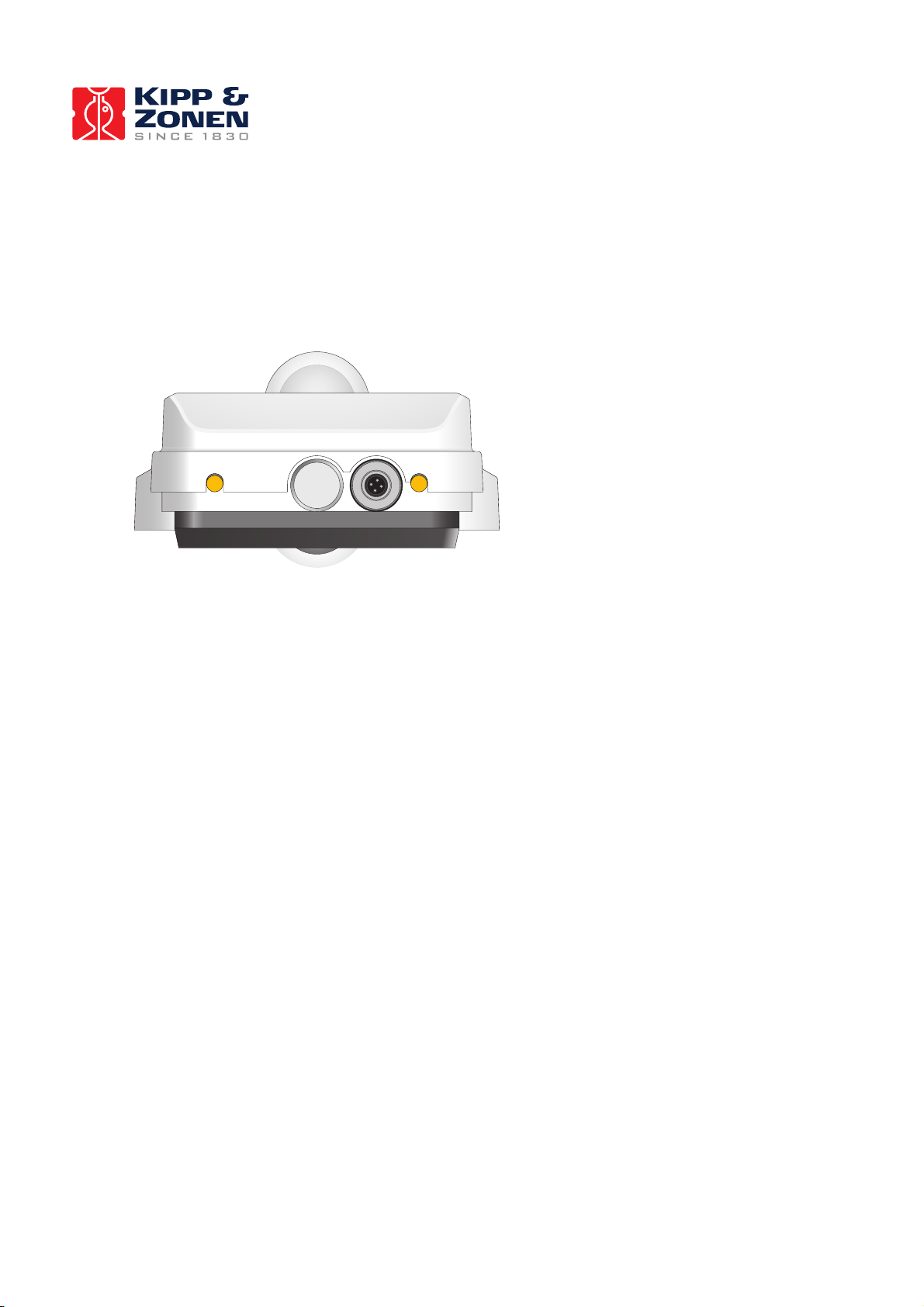
4.2 Replacing the Ventilator Filter
The CNF 4 ventilation unit has a filter that can be checked and if required cleaned or replaced. The cover of the
ventilator cover (black part in picture below) can be removed by just pulling it down from the CNR 4. The filter
needs to be checked for dust and particles every 6 – 12 months. It can be cleaned by simply washing it in clean
water or it can be replaced by a new one. To remount the cover and filter just click it back on the ventilator.
Fig 4.2 Back of CNF 4 with filter cover
Page 31

30
5 TROUBLE SHOOTING
This chapter describes what to do if there appears to be a problem. The following chapters give individual
information for checking the pyranometer, pyrgeometer, the temperature sensors and the ventilation unit with
heater.
All connections to the CNR 4 are made with connectors and cables that can be separated from the main instrument.
Check at all times that these connectors are properly attached and screwed to the body of the CNR 4.
If there is no clue as to what may be the problem, start performing the following "upside-down test", which is a
rough test for a first diagnosis. It can be performed both outdoors and indoors. Indoors, a lamp can be used as a
source for both Solar and Far Infrared radiation. Outdoors you should preferably work with a solar elevation of more
than 45 degrees (45 degrees above horizon) and of course under stable conditions (no large changes in solar
irradiance, preferably cloudless) :
1. Measure the output in the normal position. Record the measured values when the signals have stabilised,
i.e. after about 3 minutes.
2. Rotate the instrument 180 degrees, so that the upper and the lower sensors are now in the reverse
orientation as to the previous position.
3. Measure the output once more. Record the measured values when the radiometers have stabilised.
4. The calculated radiation for the sensors in the rotated position should be equal in magnitude, only differing
in sign. In a rough test like this, deviations of +/- 10 % should be tolerated. If deviations greater than this are
encountered, the following tests might help.
5.1 Testing the pyranometer
As a first test we recommend that you check the sensor impedance. It should have a nominal value between 20 and
200 Ohm. Zero, or infinite resistance indicates a failure in hardware connection.
Before starting the second test measurement, let the pyranometer rest for at least five minutes to let it regain its
thermal equilibrium. For testing, set a voltmeter to its most sensitive range setting. Darken the sensor. The signal
should read zero. Bear in mind that the response takes about one minute. Small deviations from zero are possible;
this is caused by thermal effects like touching the pyranometer with your hand. The latter effect can be
demonstrated by deliberately heating the pyranometer with your hand. Another cause might be the zero offset of
the data logger. When this is the case, the same offset will also be present when the data logger is short-circuited
with a 200 Ohm resistor. This is an amplifier error from the data logger. This amplifier error should not be larger
than 5 Watts per square meter. If the amplifier error is within specifications, proceed with the third test.
In the third test the sensor should be exposed to light. The signal should be a positive reading. Set the voltmeter
range in such a way that the expected full-scale output of the pyranometer is within the full-scale input range of the
voltmeter. The range can be estimated on theoretical considerations. (When the maximum expected radiation is
1500 Watts per square metre, which is roughly equal to normal outdoor daylight conditions, and the sensitivity of
the pyranometer is 15 µV per Watt per square metre, the expected output range of the pyranometer is 1500 times
15 which is equal to 22500 µV, or 0.0225 Volts). You can calculate the radiation intensity by dividing the
pyranometer output (0.0225 volts) by the calibration factor (0.000015 volt per watt per square metre). Still no faults
found? Your pyranometer is probably doing fine.
5.2 Testing of the pyrgeometer
It is assumed that the data logger (amplifier) circuit is the same as the one used for pyranometer, and that its zero
offset is no more than a few watts per square metre, let us say 5 Watts per square metre just as an example, (see
test in 5.1).
Page 32

31
The CNR 4 body and ambient air should be at the same temperature as much as possible. Let the pyrgeometer rest
for at least five minutes to regain its thermal equilibrium. Set the voltmeter to its most sensitive range. To test if the
pyrgeometer is working properly, we suggest putting your hand in front of the pyrgeometer. The thermal radiation
will cause pyrgeometer to generate a positive voltage when the hand's surface temperature is higher than the
pyrgeometer temperature. The pyrgeometer will generate a negative voltage if the hand is colder. The signal is
proportional to the temperature difference (see the rule of thumb of 1.1.6.5). The radiation that is emitted by the
hand can be calculated by dividing the pyrgeometer output by the calibration factor, and subsequently correcting
for the temperature, according to equation 1.2. Still no faults found? Your pyrgeometer is probably doing fine.
5.3 Testing the Pt-100
Using a meter, which measures resistance, you can check the operation of the Pt-100. If connected properly, the
resistance of two opposite wires of the Pt-100 should be measured. The value can be read in the table 1.1 and
should be above 100 Ohms (cable resistance should measure about 0.1 ohms per metre cable). When in doubt the
thermistor resistance (temperature) can be checked as well for reference
5.4 Testing the thermistor
Using a meter, which measures resistance, you can check the operation of the thermistor. If connected properly, the
resistance of two wires of the thermistor should be measured. The value can be read in the table 1.2 and should be
around 10.000 Ohms for 25 °C. (cable resistance should measure about 0.1 ohms per metre cable). When in doubt
the Pt-100 resistance (temperature) can be checked as well for reference
5.5 Testing the Heater
The optional CNF 4 consists of a heater and ventilator. Using a meter, which measures resistance you can check the
operation of the heating resistor. The value should be around 15 Ohm. (Cable resistance should measure about 0.1
ohms per metre cable).
Using a meter, which measures resistance, you can check the operation of the heater. If connected properly, the
resistance of two opposite wires of the heater should measure about 8 ohms (this includes the cable resistance for
the standard 10-meter cable). The cable resistance should measure about 0.1 ohms per metre cable. An infinite
resistance reading indicates the likelihood of a broken wire, or cable.
5.6 Testing the Ventilator
The impedance of the ventilator motor can be checked to tested for reference The value should be around 30 Ohms
(cable resistance should measure about 0.1 ohms per metre cable). In this case a correct value is measured this
does not guarantee proper operation. It is possible the ventilator is stalled by an object blocking the fan. This can
be checked by removing the cover and filter and inspecting the rotation of the fan by hand.
Page 33

32
6 CMB 1 OPTIONAL MOUNTING BRACKET
The CMB 1 mounting bracket is ideal for mounting the CNR 4 to a pole or wall. The stainless steel construction
ensures a durable fixation to almost any object. The top U bolts allow rotation of the CNR 4 rod, while the extra
screw under the front U bolt allows the rod to tilt. All mounting material for fixation to a horizontal or vertical pole
is included. The 2 different sized pairs of U bolts allow for pole sizes between 22 mm and 60 mm. Wall mounting
bolts and or plugs are not included.
Fig 7.1 CMB 1 mounting bracket with mounting material
Page 34

33
Fig 7.2 CMB 1 mounting examples with CNR 4, albedometer and pyranometer
Page 35

34
7 DELIVERY
Check the contents of the shipment for completeness (see below) and note whether any damage has occurred
during transport. If there is damage, a claim should be filed with the carrier immediately. In this case, or if the
contents are not complete, your dealer should be notified in order to facilitate the repair or replacement of the
instrument.
The CNR 4 Net-Radiometer delivery will include the following items:
A delivery includes: One CNR 4
One mounting rod
Two cables
Two drying cartridges
Four calibration values on 2 calibration sheets (long and short wave)
One CD with instruction manual
Optional CNF 4 One CNF 4 mounted to the CNR 4
One (4 wire) cable
Unpacking
Keep the original packaging for later shipments (e.g. recalibration)!
Although all sensors are weatherproof and suitable for harsh ambient conditions, they do partially consist of
delicate mechanical parts. It is recommended to use the original shipment packaging to safely transport the
equipment to the measurement site.
Page 36

35
8 RECALIBRATION SERVICE
Pyranometers, UV-meters, pyrgeometers, Net radiometers & Sunshine duration meters
Kipp & Zonen solar radiation measurement instruments comply with the most demanding international standards.
In order to maintain the specified performance of these instruments, Kipp & Zonen recommends calibration of their
instruments at least every two years.
This can be done at the Kipp & Zonen factory. Here, recalibration to the highest standards can be performed at low
cost. Recalibration can usually be performed within four weeks. If required, urgent recalibration can be
accomplished in three weeks or less (subject to scheduling restrictions). Kipp & Zonen will confirm the duration of
recalibration at all times. Please note that special quantity recalibration discounts are available.
Please contact us at:
Kipp & Zonen B.V. (head office)
Delftechpark 36
2628 XH DELFT
The Netherlands
Contact: Kipp & Zonen Calibration
Phone: +31 15 2755 210
Fax: +31 15 2620 351
Website: http://www.kippzonen.com
E-mail: info@kippzonen.com
Page 37

Our customer support remains at your disposal for any maintenance or repair, calibration,
supplies and spares.
Für Servicearbeiten und Kalibrierung, Verbrauchsmaterial und Ersatzteile steht Ihnen unsere
Customer Support Abteilung zur Verfügung.
Notre service ‘Support Clientèle’ reste à votre entière disposition pour tout problème de
maintenance, réparation ou d’étalonnage ainsi que pour les accessoires et pièces de rechange.
Nuestro servicio de atención al cliente esta a su disposición para cualquier actuación de
mantenimiento, reparación, calibración y suministro de repuestos.
HEAD OFFICE
Kipp & Zonen B.V.
Delftechpark 36, 2628 XH Delft
P.O. Box 507, 2600 AM Delft
The Netherlands
T: +31 (0) 15 2755 210
F: +31 (0) 15 2620 351
info@kippzonen.com
SALES OFFICES
Kipp & Zonen France S.A.R.L.
7 Avenue Clément Ader
ZA Ponroy - Bâtiment M
94420 Le Plessis Trévi
France
Kipp & Zonen Asia Pacific Pte. Ltd.
81 Clemenceau Avenue
#04-15/16 UE Square
Singapore 239917
Kipp & Zonen USA Inc.
125 Wilbur Place
Bohemia
NY 11716
United States of America
Go to www.kippzonen.com for your local distributor or contact your local sales office
se
T: +33 (0) 1 49 62 41 04
F: +33 (0) 1 49 62 41 02
kipp.france@kippzonen.com
T: +65 (0) 6735 5033
F: +65 (0) 6735 8019
kipp.singapore@kippzonen.com
T: +1 (0) 631 589 2065
F: +1 (0) 631 589 2068
kipp.usa@kippzonen.com
Passion for Precision
 Loading...