

Page 1
Instruction Manual
CMP series • Pyranometer
CMA series • Albedometer
Page 2

Instruction Manual - CMP/CMA series
2
Page 3

Important User Information
.
Dear customer, thank you for purchasing a Kipp & Zonen instrument. It is essential that you read this manual completely for a
full understanding of the proper and safe installation, use, maintenance and operation of your new CMP series pyranometer or
CMA series albedometer.
We understand that no instruction manual is perfect, so should you have any comments regarding this manual we will be
pleased to receive them at:
Kipp & Zonen B.V.
Delftechpark 36, 2628 XH Delft, - or
P.O. Box 507, 2600 AM Delft,
The Netherlands
T: +31 (0) 15 2755 210
F: +31 (0) 15 2620 351
support@kippzonen.com
www.kippzonen.com
Warranty and liability
Kipp & Zonen guarantees that the product delivered has been thoroughly tested to ensure that it meets its published specifications.
The warranty included in the conditions of delivery is valid only if the product has been installed and used according to the
instructions supplied by Kipp & Zonen.
Kipp & Zonen shall in no event be liable for incidental or consequential damages, including without limitation, lost profits, loss
of income, loss of business opportunities, loss of use and other related exposures, however incurred, arising from the incorrect
use of the product.
Modifications made by the user may aect the instrument performance, void the warranty, or aect the validity of the CE
declaration or other approvals and compliances to applicable International Standards.
Copyright © 2013 Kipp & Zonen B.V.
All rights are reserved. No part of this publication may be reproduced, stored in a retrieval system or transmitted, in any form
or by any means, without authorisation by Kipp & Zonen.
Kipp & Zonen reserves the right to make changes to this manual, brochures, specifications and other product documentation
without prior notice.
Manual document number: V1311
st
Publication date: 1
November 2013
Instruction Manual - CMP/CMA series
3
Page 4

Instruction Manual - CMP/CMA series
4
Page 5
Declaration of Conformity
.
We Kipp & Zonen B.V.
Delftechpark 36, 2628 XH Delft
P.O. Box 507, 2600 AM Delft
The Netherlands
Declare under our sole responsibility that the products:
Models CMP 3, CMP 6, CMP10, CMP 11, CMP 21 and CMP 22
Type Pyranometer
and
Models CMA 6 and CMA 11
Type Albedometer
to which this declaration relates are in conformity with European Harmonised Standards as published in:
Official Journal of the EC, Issue: C246 (05-10-2005)
The compliance of the product has been based on:
Emissions EN 61326-1:2000
Immunity EN 61326-1:2000
Safety EN 61010-1:2001
Radio part NA
following the provisions of the directives (if applicable):
EMC-directive 2004/108/EC
Electrical safety 2005/95/EC
st
Delft, 1
B.A.H. Dieterink
President
Kipp & Zonen B.V.
November 2013
Instruction Manual - CMP/CMA series
5
Page 6

Instruction Manual - CMP/CMA series
6
Page 7

Table of Contents
.
Important User Information
.
3.........................................................................................................................................................................................
.
3
Declaration of Conformity
Table of Contents
1 Introduction
1.1 Product overview
1.1.1 The pyranometer and albedometer
1.1.2 International Standards
1.2 The CMP 3 pyranometer
1.3 The CMP10 pyranometer
1.4 The CMP 6, CMP 11, CMP 21 and CMP 22 pyranometers
1.5 The CMA 6 and CMA 11 albedometers
2 Installation
2.1 Included with the product
2.2 Tools required
2.3 Location and support
......................................................................................................................................................................................................................
....................................................................................................................................................................................................................
........................................................................................................................................................................................................................
.......................................................................................................................................................................................................................
...............................................................................................................................................................................................
...............................................................................................................................................................................................................
...............................................................................................................................................................................
......................................................................................................................................................................................................
.................................................................................................................................................................................................
..............................................................................................................................................................................................
......................................................................................................................
................................................................................................................................................................
..........................................................................................................................................................................................
.......................................................................................................................................................................................................
2.4 Installation for measurement of horizontal global irradiance
2.4.1 Location
2.4.2 Mounting
2.4.3 Orientation
2.4.4 Levelling
2.4.5 Securing
2.4.6 Fitting the connector and cable
2.4.7 Fitting the sun shield
2.5 Installation for measurement of tilted global irradiance
......................................................................................................................................................................................................................................
....................................................................................................................................................................................................................................
................................................................................................................................................................................................................................
.....................................................................................................................................................................................................................................
.....................................................................................................................................................................................................................................
.....................................................................................................................................................................................
..........................................................................................................................................................................................................
...................................................................................................................
2.6 Installation for measurement of reflected global irradiance
2.7 Installation for measurement of albedo
..........................................................................................................................................................
2.8 Installation for measurement of horizontal diffuse irradiance
2.9 Electrical connections
2.9.1 Pyranometer connections
2.9.2 Albedometer connections
2.9.3 Grounding
2.9.4 Radiation signal output
2.9.5 Temperature signal output
....................................................................................................................................................................................................................................
....................................................................................................................................................................................................
..................................................................................................................................................................................................
...................................................................................................................................................................................................
.......................................................................................................................................................................................................
................................................................................................................................................................................................
.......................................................................................................
...........................................................................................................
......................................................................................................
5
7
9
9
9
10
11
11
12
12
13
13
14
14
14
14
15
16
16
16
16
16
16
17
17
18
18
18
19
19
19
19
3 Accessories
3.1 Diffuse radiation measurement
3.2 Ventilation
3.3 Mountings
3.4 Glare screen kit
3.5 Cables
3.6 AMPBOX
4 Operation and measurement
4.1 Data collection
.........................................................................................................................................................................................................................................
.....................................................................................................................................................................................................................
..............................................................................................................................................................................
..............................................................................................................................................................................................................................
...............................................................................................................................................................................................................................
...................................................................................................................................................................................................................
.....................................................................................................................................................................................................................................
........................................................................................................................................................................
.....................................................................................................................................................................................................................
4.2 Key parts of CMP and CMA series radiometers
4.2.1 Dome(s)
4.2.2 Detector
4.2.3 Housing
4.2.4 Drying Cartridge
4.2.5 Cable and Connector
.......................................................................................................................................................................................................................................
.......................................................................................................................................................................................................................................
........................................................................................................................................................................................................................................
.....................................................................................................................................................................................................................
.............................................................................................................................................................................................................
............................................................................................................................................
7
21
21
21
21
21
21
21
23
23
23
25
25
25
26
26
Page 8

.
.
5 Maintenance and Re-calibration
5.1 Daily maintenance
5.2 Monthly maintenance
5.3 Yearly maintenance
5.4 Calibration
5.4.1 Calibration principle
5.4.2 Calibration traceability to the WRR
...............................................................................................................................................................................................................................
.............................................................................................................................................................................................................
......................................................................................................................................................................................................
...........................................................................................................................................................................................................
.............................................................................................................................................................................................................
.............................................................................................................................................................................
..............................................................................................................................................................
.
27
27
27
27
27
28
28
6 Specifications
6.1 Optical and electrical
6.2 Dimensions and weight
7 Trouble shooting
7.1 Output signal not present or incorrect
7.2 Frequently asked questions
8 Customer support
9 Keyword index
.................................................................................................................................................................................................................
.....................................................................................................................................................................................................
.................................................................................................................................................................................................
........................................................................................................................................................................................................
..............................................................................................................................................................
.......................................................................................................................................................................................
......................................................................................................................................................................................................
...............................................................................................................................................................................................................
Appendix A. Pyranometer physical properties
A.1 Spectral range
A.2 Sensitivity
A.3 Response time
A.4 Impedance
A.5 Non-linearity
A.6 Tempearture dependence
A.7 Tilt error
A.8 Zero offset type A
A.9 Zero offset type B
A.10 Operating temperature
A.11 Field of view
A.12 Directional response
A.13 Maximum irradiance
A.14 Non-stability
A.15 Spectral selectivity
A.16 Environmental
A.17 Uncertainty
..........................................................................................................................................................................................................................
..................................................................................................................................................................................................................................
.............................................................................................................................................................................................................................
...................................................................................................................................................................................................
.......................................................................................................................................................................................................................................
...................................................................................................................................................................................................................
...................................................................................................................................................................................................................
........................................................................................................................................................................................................
..............................................................................................................................................................................................................................
.............................................................................................................................................................................................................
.............................................................................................................................................................................................................
..............................................................................................................................................................................................................................
................................................................................................................................................................................................................
..........................................................................................................................................................................................................................
.................................................................................................................................................................................................................................
.......................................................................................................................................
29
29
29
31
31
31
33
35
37
37
37
37
37
37
38
38
38
39
39
39
39
39
39
40
40
40
Appendix B. Pyranometer classification to ISO 9060:1990(E)
Appendix C. 10kΩ Thermistor specifications
Appendix D. Pt-100 specifications
.......................................................................................................................................................................
...........................................................................................................................................
.......................................................................................
Using this table
Click on any item in the table of contents to be taken directly to the relevant page.
Click on the Kipp & Zonen logo at the bottom of any page to be taken back to the table of contents.
8
41
43
45
Page 9
1. Introduction
.
Throughout this manual the following symbols are used to indicate to the user important information.
General warning about conditions, other than those caused by high voltage electricity, which may result in physical
injury and/or damage to the equipment or cause the equipment to not operate correctly.
Note Useful information for the user
1.1 Product overview
According to International Standard ISO 9060:1990 and the World Meteorological Organisation (WMO) a pyranometer is the
designated type of instrument for the measurement of hemispherical (global or diuse) solar radiation integrated over the
wavelength range from 0.3 to 3 m (300 to 3000 nm). All pyranometers within the CMP series are compliant with one of the
classes specified by the international standard.
The albedo of a surface is the extent to which it diusely reflects short-wave radiation from the sun in the wavelength range from
300 to 3000 nm. It is the ratio of the reflected radiation to the incoming radiation and varies from 0 (dark) to 1 (bright). As an
indication, albedo is about 0.15 for grass, 0.5 for dry sand and 0.8 for fresh snow.
CMA series albedometers consist of two pyranometers. The upper measures incoming global solar radiation and the lower
measures solar radiation reflected from the surface below. When the two signal outputs have been converted to irradiance in W/m²,
the albedo can be simply calculated.
This manual, together with the instruction sheets, provide information related to the installation, maintenance, calibration,
product specifications and applications of the CMP series pyranometers and CMA series albedometers.
If any questions should remain, please contact your local Kipp & Zonen representative or e-mail the Kipp & Zonen customer and
product support department at: support@kippzonen.com
Please go to www.kippzonen.com for information about other Kipp & Zonen products, or to check for any updates to this manual.
1.1.1 The pyranometer and albedometer
The CMP series instruments are high quality radiometers designed for measuring short-wave irradiance on a plane surface
(radiant flux, W/m²) which results from the sum of the direct solar radiation and the diuse sky radiation incident from the
hemisphere above the instrument. The CMA series also measures the amount of the incoming radiation which is reflected by the
surface below.
There are six models in the CMP series; CMP 3, CMP 6, CMP10, CMP 11, CMP 21 and CMP 22; and two models in the CMA series,
CMA 6 and CMA 11.
To achieve the required spectral and directional characteristics CMP series pyranometers and CMA series albedometers use
thermopile detectors and glass domes. They have built-in bubble levels and the pyranometers have adjustable levelling feet.
Snap-on sun shields reduce solar heating of the housings. Albedometers have a mounting rod fitted and an integral glare-
shield to prevent direct sunlight from below the horizon entering the lower pyranometer. The waterproof connectors have
gold-plated contacts.
The instruments are normally delivered with a waterproof plug pre-wired to a high quality signal cable, typically this is 10 m
long but other lengths are available. The instruments can also be ordered with a plug only, for the user to fit their own cable.
Instruction Manual - CMP/CMA series
9
Page 10

.
CMP pyranometers and CMA albedometers do not require power to operate. Radiation falling onto the sensing element produces
a small analogue output voltage.
CMP 3 is smaller and lighter than the other CMP series pyranometers. It features a 64-junction thermopile sensing element with
a highly absorptive and spectrally flat black coating to capture incoming radiation and convert it to an electrical signal. This
detector is protected by a high quality glass dome which is 4 mm thick. The housing is completely sealed.
CMP 6 uses the same sensing element as CMP 3 but has improved performance due to the double glass dome construction and the
increased thermal mass of the larger housing. The glass used has better transmission of ultraviolet radiation than the CMP 3 glass.
The two high quality concentric domes, 2 mm thick, reduce directional error and improve thermal isolation. The radiometric
levelling is more accurate and CMP 6 has a drying cartridge with replaceable desiccant.
CMP10 and CMP 11 have a 32-junction thermopile sensing element which features faster response, better linearity and a wider
measurement range than the CMP 3 and CMP 6. CMP10 and CMP 11 have built-in temperature compensation. The CMP10 has
internal desiccant that lasts for 10 years and the CMP 11 has a removable drying cartridge.
CMP 21 is similar to the CMP 11 but has individually optimised temperature compensation and a sensor is fitted to monitor the
housing temperature. Each instrument is supplied with its own temperature and directional response for post-processing of
recorded data by the user. A Pt-100 temperature sensor can be ordered instead of the standard 10 kΩ thermistor.
CMP 22 has all the features of CMP 21 but uses two 4 mm thick very high quality quartz domes for a wider spectral range and reduced
thermal osets. Because of the high optical quality and refractive index of these domes the directional error is greatly reduced.
CMA 6 is an albedometer comprised of two CMP 6 sensing element and dome assemblies in a single housing with two signal
outputs on one signal connector.
CMA 11 uses two of the same sensing elements as fitted to the CMP 11 pyranometer, for similarly improved performance over the CMA 6.
Features and specifications of the CMP and CMA instruments are explained later in this manual.
1.1.2 International Standards
CMP 3 exceeds the requirements of ISO 9060:1990 for a Second Class Pyranometer.
CMP 6 and CMA 6 are fully compliant with the requirements of ISO 9060:1990 for a First Class Pyranometer.
CMP10, CMP 11 and CMA 11 are fully compliant with the requirements of ISO 9060:1990 for a Secondary Standard Pyranometer.
CMP 21 and CMP 22 significantly exceed the requirements of ISO 9060:1990 for a Secondary Standard Pyranometer.
CMP series pyranometers and CMA series albedometers are calibrated in accordance with Annex A.3 of ISO 9847 ‘Calibration of
Field Pyranometers by Comparison to a Reference Pyranometer’. Annex A.3 refers to ‘Calibration Devices Using Artificial Sources’.
Calibrations are traceable to the World Radiometric Reference (WRR) in Davos, Switzerland.
CMP series pyranometers comply with IEC 60904-1 ‘Photovoltaic devices - Part 1: Measurement of Photovoltaic Current-Voltage
Characteristics’.
Instruction Manual - CMP/CMA series
10
Page 11
1.2 The CMP 3 pyranometer
glass dome
detector
housing
1.3 The CMP10 pyranometer
sun shield
fixed foot
sun shield
connector
bubble level
adjustable feet
outer glass dome
inner glass dome
detector
bubble level
connector
desiccant
fixed foot
housing
adjustable feet
Instruction Manual - CMP/CMA series
11
Page 12
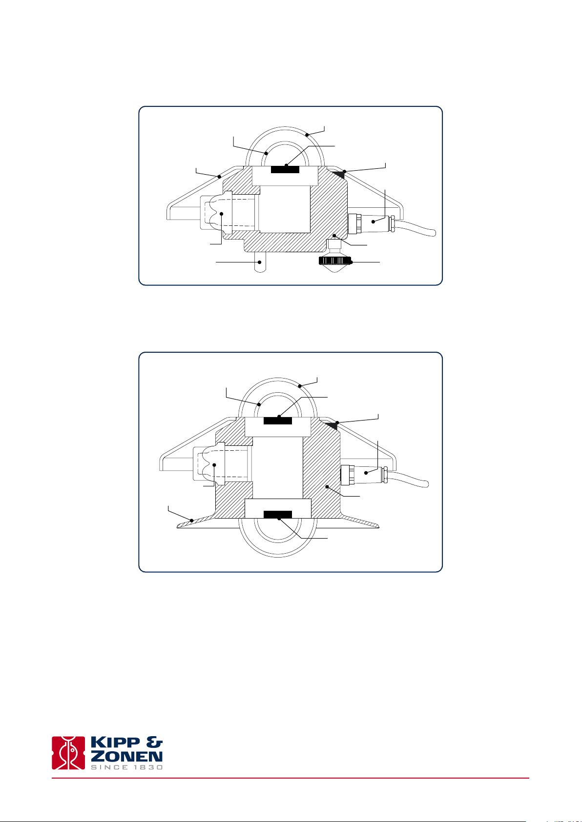
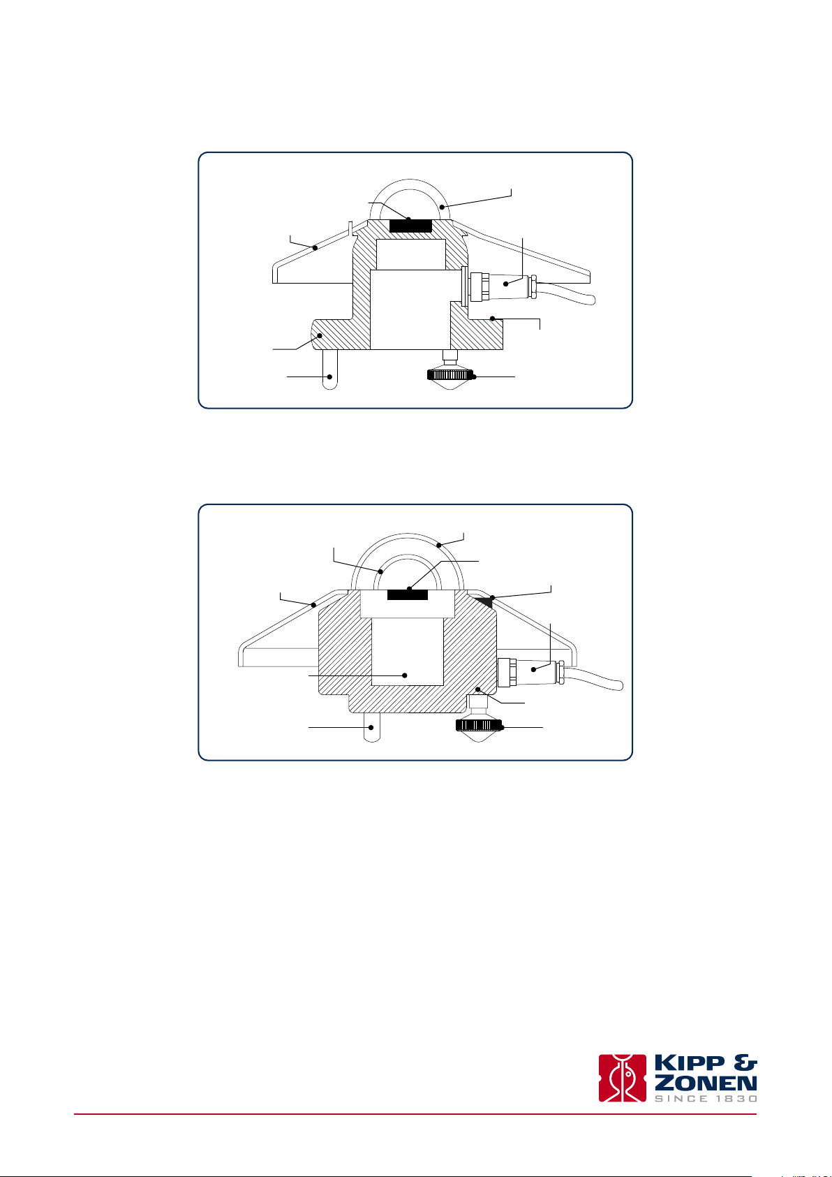
1.4 The CMP 6, CMP 11, CMP 21 and CMP 22 pyranometers
inner glass dome
sun shield
drying cartridge
fixed foot adjustable feet
1.5 The CMA 6 and CMA 11 albedometers
inner glass dome
outer glass dome
detector
bubble level
connector
housing
outer glass dome
upper detector
bubble level
drying cartridge
integral glare screen
connector
housing
lower detector
Instruction Manual - CMP/CMA series
12
Page 13
2. Installation
.
Please follow the instructions in this section carefully, and also refer to the instruction sheets, for the correct mechanical and
electrical installation of the CMP and CMA series radiometers.
2.1 Included with the product
Check the contents of the shipment for completeness (see below) and note whether any damage has occurred during transport. If
there is damage, a claim should be filed with the carrier immediately. In the case of damage and/or the contents are incomplete,
contact your local Kipp & Zonen representative or e-mail the Kipp & Zonen customer and product support department at:
support@kippzonen.com
Although all CMP and CMA radiometers are weather-proof and suitable for use in harsh environmental conditions, they have
some delicate mechanical parts. Please keep the original packaging for safe transport of the radiometer to the measurement
site, or for use when returning the radiometer for calibration.
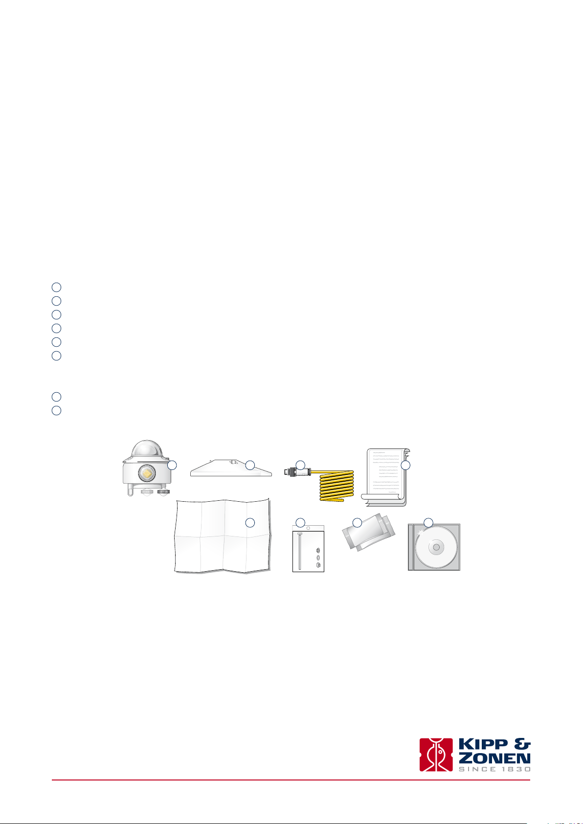
The following items are included with CMP series pyranometers:
1
Pyranometer
2
Sun shield
3
Cable, pre-wired with connector (2, 4 or 8 pins) or connector only for customer cable
4
Calibration certificate (with temperature response and directional response for CMP 21 and CMP 22)
5
Instruction sheet
6
Pyranometer fixing kit CMP 3; 2 each of stainless steel M5 x 30, M5 x 40 and M5 x 50 mm screws, nut, flat washer
Pyranometer fixing kit CMP 6, CMP10, CMP 11, CMP 21 and CMP 22; 2 each of stainless steel M5 x 80 mm screw, nut, flat
washer, nylon insulation ring
7
2 Dessicant bags,
CD-ROM with product documentation
8
except for CMP 3 (which is sealed) and CMP10 (desiccant lasts for 10 years, will be renewed every factory re-calibration)
1
2
5
3
6
2x
2x
2x
2x
7
4
8
Instruction Manual - CMP/CMA series
13
Page 14
.
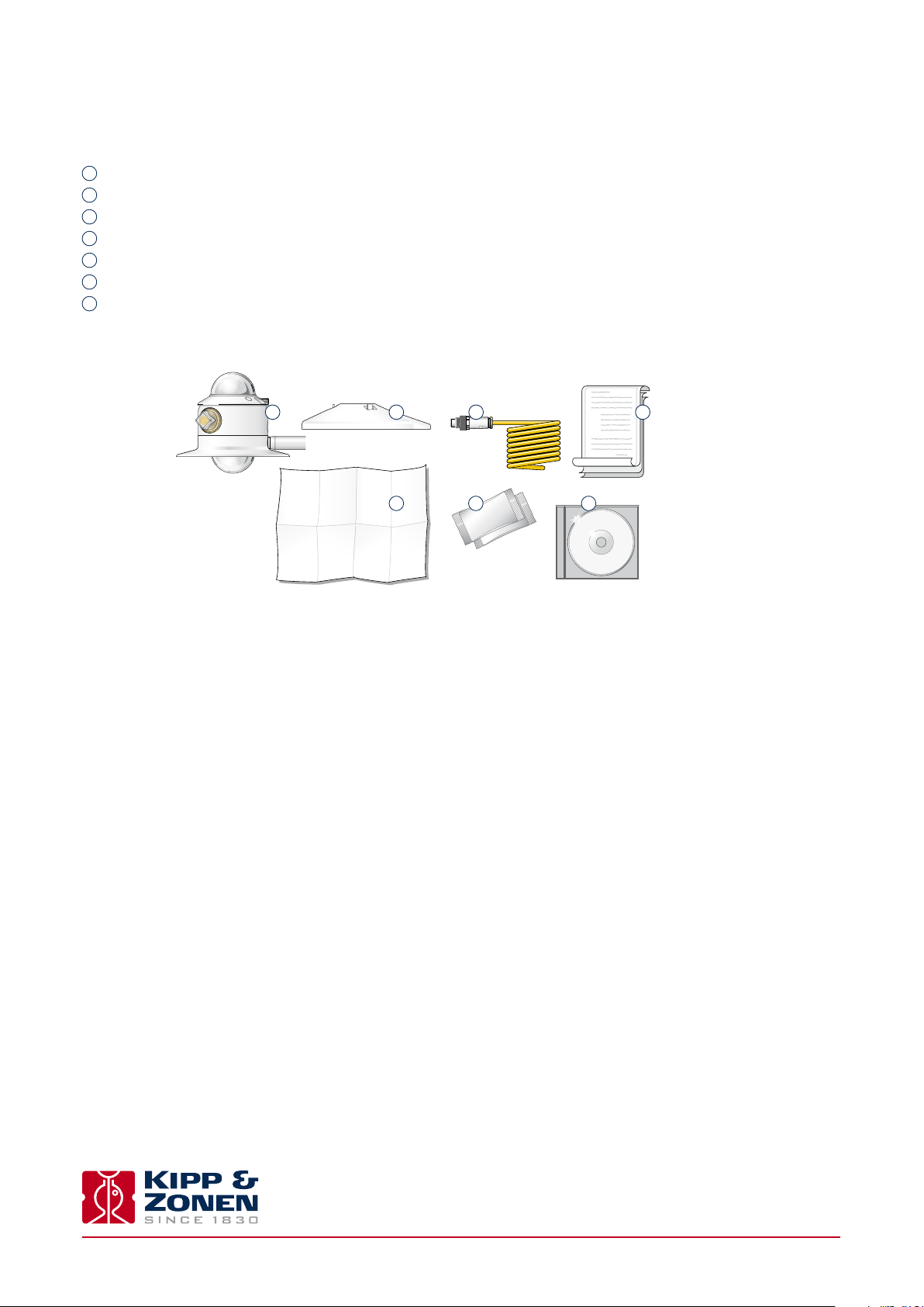
The following items are included with CMA series albedometers:
Albedometer with permanently fitted mounting rod
1
2
Sun shield
3
Cable, pre-wired with connector (4 pins) or connector only for customer cable
4
Calibration certificate
5
Instruction sheet
6
2 Dessicant bags
7
CD-ROM with product documentation
1
2
5
3
6
7
4
2.2 Tools required
The tools required to fit a CMP series pyranometer to a support are a 4 mm (M5 socket head screw) Allen key and an 8 mm (M5
nut) wrench/spanner. Tools required for the CMA series albedometers depend upon how the mounting rod will be attached to a
mast or wall (fittings are not included). Normally, the drying cartridge should be hand-tight, but a 16 mm or 5/8" open-ended
wrench/spanner can be used to loosen it.
2.3 Location and support
The Instruction sheets contain all the outline information necessary for the correct installation of the radiometers. Further
details for specific types of installation and application are given later in this section.
Check the condition of the desiccant and replace before installation, if necessary; for example after a long storage period.
Not required for CMP 3. The CMP10 internal desiccant is operational 10 years after the last calibration date as mentioned on
the instrument label and calibration certificate.
2.4 Installation for measurement of horizontal global irradiance
The following steps must be carefully taken for optimal performance of the instrument.
2.4.1 Location
Ideally, the site for the radiometer should be free from any obstructions to the hemispherical view from the plane of the sensing
element. If this is not possible, the site should be chosen in such a way that any obstruction over the azimuth range between
earliest sunrise and latest sunset should have an elevation not exceeding 5 ° (the apparent sun diameter is 0.5 °)
Instruction Manual - CMP/CMA series
14
Page 15

This is important for an accurate measurement of the direct solar radiation component. The diuse solar radiation is less
influenced by obstructions near the horizon. For instance, an obstruction with an elevation of 5° over the whole azimuth range
of 360 ° decreases the downward diuse solar radiation by only 0.8%.
It is evident that the radiometer should be located in such a way that a shadow will not be cast upon it at any time (for example
by masts). Note that hot exhaust gas (> 100 °C) from ventilation ducts will produce some radiation in the spectral range of the
radiometer and cause an oset in the measurements. The radiometer should be distant from light-coloured walls or other
objects likely to reflect sunlight onto it, or emitting short-wave radiation.
The radiometer should be readily accessible for cleaning the outer dome, checking that it is level and inspecting the desiccant.
2.4.2 Mounting
The CMP pyranometer is provided with two holes for 5 mm screws. Two each of stainless steel screws, washers and nuts are
provided in the fixing kit, and two nylon insulation rings (except for CMP 3). The pyranometer should first be secured lightly with
the screws to a solid and stable mounting stand or platform, as shown below. The nylon insulators are important to prevent
corrosion between the stainless steel screws and the aluminium pyranometer housing (they are not supplied with CMP 3, where
mounting through the base flange is less critical).
The mounting stand temperature may vary over a wider range than the air temperature. Temperature fluctuations of the
pyranometer body can produce oset signals, therefore it is recommended to isolate the pyranometer thermally from the
mounting stand by placing it on its three feet. However, ensure that there is a good electrical contact with the ground to conduct
away currents in the cable shield induced by lightning.
M5 x 80 mm screw (2x)
Nylon insulation rings (2x)
h
>10 x h
max. 100 m
Ø 5.2 mm (2x)
Flat washer (2x)
Nut (2x)
65 mm
Note After recalibration and/or reinstallation ensure that the nylon insulators are refitted.
>1 MΩ Impedance
mV
Instruction Manual - CMP/CMA series
15
Page 16

.
CMA albedometers are fitted with a mounting rod with a flat on the top surface that is pre-aligned with the horizontal axis of the
radiometer. The rod is 16 mm diameter and extends approximately 300 mm beyond the sun shield. The CMB 1 mounting bracket
can be used for fixing the mounting rod to a mast, pole or wall. Also refer to the requirements in 2.6 and 2.7 for the measurement
of reflected radiation and albedo.
CMP 3 has an accessory mounting rod which screws into the base flange of the pyranometer. The rod is 12 mm diameter and
300 mm long and can be used with the CMB 1 mounting bracket.
CMF 1 and CMF 2 mounting fixtures for unventilated or ventilated (respectively) CMP series pyranometers have similar mounting
rods to the albedometers and can also be used with the CMB 1.
2.4.3 Orientation
In principle no special orientation of the instrument is required, although the World Meteorological Organisation (WMO) recommends
that the signal lead (connector) is pointed towards the nearest pole, to minimise heating of the electrical connections. This is also
where any mounting pole, or other support, should be located in order that shadows do not fall on the instrument.
2.4.4 Levelling
Accurate measurement of the global radiation requires proper levelling of the detector surface. Level the instrument by turning
the two adjustable feet to bring the bubble of the spirit level centrally within the marked ring. For easy levelling, first use the
screw nearest to the spirit level.
Note It is ideal that the bubble should be completely within the marked ring. However, in fact, the pyranometer is level
within the specified accuracy when the bubble is at least half within the ring.
2.4.5 Securing
Fix the pyranometer tightly with the two stainless steel bolts. For albedometers tighten the mounting rod fixings. Ensure that
the radiometer maintains the correct levelled position when it is secured.
.
2.4.6 Fitting the connector and cable
Locate the plug correctly in the radiometer socket, it only fits one way, and push it in. Screw the plug locking ring hand-tight.
Over-tightening may damage the waterproof seal. Secure the cable so that it cannot blow in the wind or cause a shadow on the
instrument.
Note The cable should be arranged with a curve below the instrument so that water drips o, rather than running along
the cable up to the connector.
2.4.7 Fitting the sun shield
Finally, clip on the sun shield to prevent excessive heating of the radiometer body. The bubble level is visible through the top
of the sun shield for routine checks and the shield ‘tail’ helps to protect the connector.
2.5 Installation for measurement of tilted global irradiance
When a pyranometer is mounted on a large flat tilted surface the temperature of this surface can rise considerably (more than
10 °C) above air temperature. It improves the measurement accuracy when the body is thermally isolated by its feet from the
surface. This promotes thermal equilibrium between the dome(s) and the housing and decreases zero osets. It is advised to
pre-adjust the levelling feet on a horizontal surface for easy mounting of the instrument parallel to the inclined surface.
Instruction Manual - CMP/CMA series
16
Page 17

.
For accurately and securely fixing a pyranometer at an angle to a surface an adjustable tilt mounting kit is available. See Accessories
in chapter 3.
2.6 Installation for measurement of reflected global irradiance
In the inverted position the pyranometer measures reflected global radiation. The
height above the surface (H) depends upon its roughness. The WMO recommends
a height of 1 m to 2 m above a uniform surface covered by short grass.
The mounting device should not interfere significantly with the field of view of
the instrument. The mounting plate above the pyranometer prevents excessive
heating of the housing by downwards solar radiation. CMF 1 or CMF 2 mounting
fixtures can be used. The accessory glare screen kit has an angle of 5 ° and is
fitted to the pyranometer to prevent direct illumination of the domes by the sun
at sunrise and sunset. It does not fit the CMP 3.
Thermal oset signals generated in the pyranometer are 5 times more significant
in the measurement of reflected radiation due to the lower irradiance level.
The mast shown intercepts a fraction D/2πS. of the radiation coming from the
ground. In the most unfavourable situation (sun at zenith) the pyranometer
shadow decreases the signal by a factor R²/H².
R S
H
Pyranometer
Glare screen (white)
D
Mast (black)
Equator
As a guide, a black shadow below the pyranometer with a radius of 0.1 x H decreases the signal by 1%, and 99 % of the signal
will originate from an area with a radius of 10 x H.
2.7 Installation for measurement of albedo
An albedometer consists of two identical pyranometers that measure the
incoming global solar radiation and the radiation reflected from the surface
below. Albedo is the ratio of the two irradiances, and varies from 0 (dark) to
1 (bright).
Two CMP 3’s can be mounted back to back with the standard fixing kit, and
the accessory mounting rod screwed into one of them, to make a second
class albedometer.
For two of the larger CMP pyranometers a mounting fixture is required. The
CMF 1 is used for unventilated pyranometers and the CMF 2 for ventilated
instruments. The glare screen kit should be fitted to the lower pyaranometer.
The requirements for installation of the upper pyranometer are the same as
for horizontal global irradiance. The requirements for installation of the
lower pyranometer are the same as for reflected global irradiance.
Albedo
mounting plate
R S
H
Sun shield (white)
Pyranometers
Glare screen (white)
D
Mast (black)
Equator
The same principles apply to the CMA 6 and CMA 11 albedometers, which already have an upper sun shield and an integrated
lower glare screen and mounting rod.
Instruction Manual - CMP/CMA series
17
Page 18

2.8 Installation for measurement of horizontal diffuse irradiance
For measuring the diuse radiation from the sky, the direct solar radiation
must be blocked from the pyranometer dome(s).
A static shadow ring can be used to intercept the direct solar radiation. This
requires frequent manual adjustment as the sun’s arc in the sky changes. At
times the shadow ring also intercepts a significant proportion of the diuse
sky radiation. Therefore, post-processing of the recorded data is necessary to
correct for this.
Sun
Pyranometer
Equator
Sun
Shadow ring
Mount
Kipp & Zonen produces a universal shadow ring, model CM 121, which is
suitable for use at all latitudes.
Shadow ball
Pyranometer
The alternative to a shadow ring is to use a two-axis automatic sun tracker,
such as one of the Kipp & Zonen SOLYS 2 or 2AP. The sun tracker uses location
and time information to calculate the position of the sun and point at it
accurately under all weather conditions.
Shading assembly
Sun tracker
The sun tracker can be fitted with a small sphere mounted on an articulated
shading assembly. The shadow of the sphere is adjusted to cover the
pyranometer dome(s) completely and it will then be shaded correctly
throughout the year without adjustment.
2.9 Electrical connections
As standard CMP pyranometers and CMA albedometers are supplied with a waterproof connector pre-wired to 10 m of high quality
yellow cable with 2, 4 or 8 wires and a shield covered with a black sleeve. Longer cables of 25 m and 50 m length are available as
options and 100 m on special request. The colour code of the wires and the connector pin numbers are shown below and on the
instruction sheets.
Note Where the cable needs to be longer than 50 m, the AMBOX 4 to 20 mA signal amplifier is recommended.
2.9.1 Pyranometer connections
CMP 3, CMP 6, CMP10 and CMP 11 are fitted with a 2-pin connector and 2-wire shielded cable. CMP 21 and CMP 22 are fitted with
a 4-pin connector and 4-wire shielded cable, the 2 extra connections are for the standard 10kΩ thermistor temperature sensor
signal. CMP 21 and CMP 22 with the optional Pt-100 temperature sensor are fitted with an 8-pin connector and 8-wire shielded
cable, two wires are not used.
RADIATION SIGNAL
Wire Function Connect with
Red + + (Hi)
1
Blue
2
Shield
- -
Housing Ground
(Lo)
Thermistor (CMP 21 and CMP 22)
3
4
Pt-100 (Optional for CMP 21 and CMP 22)
4
6
3
5
Instruction Manual - CMP/CMA series
Green
Yellow
Yellow
Brown
Green
Grey
Combined
Combined
Thermistor
Pt-100
18
Page 19

.
2.9.2 Albedometer connections
CMA 6 and CMA 11 are fitted with a 4-pin connector and 4-wire shielded cable.
RADIATION SIGNAL
Wire Function Connect with
Red + (Hi)
1
Blue
2
Green + (Hi)
3
Yellow
4
Shield Housing Ground
2.9.3 Grounding
The shield of the cable is connected to the aluminium radiometer housing through the connector body. Preferably,
secure the radiometer with its levelling screws to a metal support with a good connection to ground (e.g. by using
a lightning conductor) and do not connect the cable shield.
If there is no good ground connection at the pyranometer, the shield at the cable end should be connected to
ground at the readout equipment. Lightning can induce high voltages in the shield but these will be led o at the
pyranometer or readout equipment.
Upper
Lower
-
-
(Lo)
(Lo)
2.9.4 Radiation signal output
The radiometers produce a low-level analogue voltage output. Each radiometer (each ‘half’ of an albedometer) has a unique
sensitivity, which is given on the serial number label on the instrument and on the calibration certificate.
The sensitivity is in the range of 5 to 20 V/W/m².
Therefore, to accurately measure changes in irradiance of 1 W/m² the data logger or data acquisition system requires a total
input measurement uncertainty (error) of 5 V, or less; including noise, osets, resolution, temperature eects, etc.
The maximum irradiance under natural sunlight is unlikely to exceed 1500 W/m².
The signal output can be connected to a single-ended or dierential measurement system input.
Note The input impedance of the readout equipment should be > 1 MΩ.
Note The output signal can be negative at night-time. This is normal and is not a fault (see section 7.2).
2.9.5 Temperature signal output
The CMP 21 and CMP 22 are fitted with an internal temperature sensor close to the cold-junction of the thermopile sensing
element. Recording this signal allows post-processing of the radiation signal data to remove the small eect of temperature
changes not compensated for by the internal circuit. The individual temperature response of each CMP 21 and CMP 22 is provided
with the calibration certificate.
For the standard 10 kΩ thermistor temperature sensor the conversion from resistance to temperature is given in Appendix C.
For the optional Pt-100 temperature sensor the conversion from resistance to temperature is given in Appendix D.
Instruction Manual - CMP/CMA series
19
Page 20

Instruction Manual - CMP/CMA series
20
Page 21

3. Accessories
.
Below is a brief description of the accessories available for CMP series pyranometers. Detailed information can be found on our
website, where the brochures and manuals for these accessories can be viewed and downloaded. The only accessories available
for the CMA series albedometers are the CMB 1 mounting bracket and the AMPBOX 4 to 20 mA signal amplifier (two amplifiers
are required).
3.1 Diffuse radiation measurement
For measuring diuse radiation a shading device is required. Kipp & Zonen can oer several options for CMP pyranometers:
Shadow ring CM 121B for a CMP 3 or an unventilated CMP 6, CMP10, CMP 11, CMP 21 or CMP 22
Shadow ring CM 121C for a ventilated CMP 6, CMP10, CMP 11, CMP 21 or CMP 22
This shadow ring needs to be adjusted manually every 3-5 days and corrections made for the part of the sky obscured by the ring.
An automated and more accurate way to measure diuse radiation is to use an automatic sun tracker fitted with a shading mech-
anism:
2AP sun tracker + shading ball assembly
SOLYS 2 sun tracker + shading ball assembly
3.2 Ventilation
To further improve measurement accuracy of the CMP 6, CMP10, CMP 11, CMP 21 or CMP 22 pyranometers the CVF4 ventilation unit
can be used. CVF4 operates from 12 VDC, has a tacho pulse output to monitor the fan speed, and both 5 Watt and 10 Watt heaters.
The advantages of a CVF4 are:
Lower thermal offsets
No precipitation or condensation on the dome
Less dirt on the dome
Frost, snow or ice can be melted
Less frequent cleaning required
No ventilation unit is available for the CMP 3 pyranometer or the CMA 6 and CMA 11 albedometers.
3.3 Mountings
For mounting pyranometers the following plates and brackets are available:
Mounting rod for CMP 3
CMF 1 mounting fixture with rod for mounting one or two unventilated CMP 6, CMP10, CMP 11, CMP 21 or CMP 22
CMF 2 mounting plate with rod for mounting one or two ventilated CMP 6, CMP10, CMP 11, CMP 21 or CMP 22
CMB 1 mounting bracket to fix and adjust a mounting rod to a mast, pole or wall
Adjustable tilt mounting kit allows tilting of a CMP pyranometer (e.g. in the same plane as a PV panel), It has a
clear scale for setting the desired angle.
3.4 Glare screen kit
When a CMP 6, CMP10, CMP 11, CMP 21 or CMP 22 pyranometer is mounted looking downwards, to measure reflected radiation,
it should be fitted with the glare screen kit. The screen blocks radiation coming from the 5 ° below the horizon of the pyranometer,
to prevent direct illumination of the domes by the sun at sunrise and sunset. CMA albedometers have an integral glare screen.
Instruction Manual - CMP/CMA series
21
Page 22

3.5 Cables
As standard a 10 m long cable with a pre-wired waterproof connector plug is supplied. Optional longer cables are available, or
a loose connector only for you to fit to your own cable.
10 m cable with connector (standard)
25 m cable with connector
50 m cable with connector
Loose connector without cable
100 m cable with connector (on special request)
Note 100 m is the maximum length of cable that does not significantly aect the radiometer sensitivity and other
characteristics.
3.6 AMPBOX
For customers who require an industry standard output, or to use long cables, the AMPBOX signal amplifier converts the low
level radiometer voltage output to a 4 to 20 mA current loop signal. For a CMA albedometer, two AMPBOX units are required.
When supplied with a new pyranometer or albedometer the AMBOX is adjusted such that the radiometer/AMPBOX pair gives
an output where 4 to 20 mA represents 0 to 1600 W/m².
Instruction Manual - CMP/CMA series
22
Page 23

4. Operation and measurement
.
CMP series pyranometers and CMA albedometers only require a suitable source of radiation (light) to operate and make
measurements, no power is required. However, it is necessary to connect them to some sort of readout or data storage device
in order to save the measurements, there is no internal data memory.
4.1 Data collection
An optimal setting for the data interval is to sample every second and store one minute averages. For setting up the combination
of radiometer and data storage please refer to the manual of the data collection device.
Take care to match the output range of the pyranometer to the input range of the data collection device to maximise the availa-
ble resolution and minimise noise.
This can be done by determining the maximum expected analogue output of the pyranometer in your application and taking the
minimum input range of your data collection device that can just handle that signal. Also refer to section 2.9.4.
4.2 Key parts of CMP and CMA series radiometers
The detectors of the radiometers are based on a passive thermal sensing element called a thermopile. Although the detector
construction diers between models, the fundamental working principle is applicable to all the radiometers.
The thermopile responds to the total energy absorbed by a unique black surface coating developed by Kipp & Zonen, which is
spectrally non-selective. The thermopile warms up and the heat generated flows through a thermal resistance to a heat-sink, the
pyranometer housing. The temperature dierence across the thermal resistance of the detector is converted into a small voltage
as a function of the absorbed irradiance.
The rise of temperature in the thermopile is easily aected by wind, rain and thermal radiation losses to the environment (for
example, a 'cold' sky) and the delicate black coating must be protected. Therefore the detector is shielded by two domes (except
for the entry-level CMP 3, which has only one dome to reduce size and cost). These domes allow equal transmittance of the direct
solar radiation component for every position of the sun in the hemisphere above the detector.
glass dome
detector
sun shield
housing
fixed foot adjustable feet
connector
bubble level
Key parts of the CMP 3 pyranometer
Instruction Manual - CMP/CMA series
23
Page 24

.
inner glass dome
sun shield
desiccant
fixed foot adjustable feet
outer glass dome
detector
bubble level
connector
housing
Key parts of the CMP10 pyranometer
inner glass dome
sun shield
drying cartridge
fixed foot adjustable feet
outer glass dome
detector
bubble level
connector
housing
Key parts of the CMP 6, CMP 11, CMP 21 and CMP 22 pyranometers
inner glass dome
outer glass dome
upper detector
bubble level
connector
drying cartridge
integral glare screen
Key parts of the CMA 6 and CMA 11 albedometers
Instruction Manual - CMP/CMA series
24
housing
lower detector
Page 25

.
A drying cartridge in the radiometer housing is filled with replaceable silica gel and prevents condensation on the inner
sides of the domes, which can cool down considerably on clear windless nights. The CMP 3 has a sealed construction with a
non-replaceable internal drying cartridge. The CMP10 has an internal desiccant that lasts for 10 years.
4.2.1 Dome(s)
The material of the radiometer dome(s) defines the spectral measurement range of the instrument. In general 97 to 98 % of the
solar radiation spectrum will be transmitted through the domes and will be absorbed by the detector. The solar irradiance can
come from any direction within the hemisphere above the radiometer and therefore the domes are designed to minimize errors
in measurement at all incident angles (the directional response).
CMP 3 pyranometers have a single 4 mm thick optical quality glass dome. CMP 6, CMP10, CMP 11 and CMP 21 have one inner
dome and one outer dome. Each is 2 mm thick and of higher quality glass, with a broader spectral range and finer finishing and
tolerances than the CMP 3. CMP 22 has two 4 mm thick domes of very high quality optical quartz.
4.2.2 Detector
The thermopile sensing element is made up of a large number of thermocouple junction pairs connected electrically in series.
The absorption of thermal radiation by one of the thermocouple junctions, called the active (or ‘hot’) junction, increases its
temperature. The dierential temperature between the active junction and a reference (‘cold’) junction kept at a fixed temper-
ature produces an electromotive force directly proportional to the dierential temperature created.
This is a thermoelectric eect. The sensitivity of a radiometer depends on the individual physical properties of the thermopile
and its construction. The sensitivity of each thermopile is unique and therefore each radiometer has an individual calibration
factor. This sensitivity is given in the calibration certificate and is on the serial number label attached to the instrument.
The unique black coating on the top surface of the thermopile has a rough structure that eectively ‘traps’ more than 97 % of the
incident radiation and heats up the hot junctions. The black-coated thermopile forms the detector, which has a spectral selectivity
of less than 2 %. This means that within the spectral range of the pyranometer, the absorption for each wavelength is equal to
within 2%. The black absorptive coating is one of the most crucial and delicate parts of the pyranometer, Kipp & Zonen’s provides
the best possible stability over a long period of time under all meteorological circumstances.
4.2.3 Housing
The instrument housing accommodates all the key parts of a radiometer. The anodized aluminium parts are light weight and give
high mechanical and thermal stability to the instrument. The stainless steel fixings are isolated where necessary to prevent
electrolytic corrosion.
Due to fine mechanical construction, Kipp & Zonen pyranometers and albedometers are virtually sealed and comply with
international standard IP 67. Pyranometers have one fixed foot and two adjustable feet and can be levelled using the integral
bubble level. For all except the CMP 3, the bubble level is visible from above without removing the snap-on white sun shield
(CMP 3 has the bubble level in the base flange). The sun shield acts to protect all the external parts and to reduce solar heating
of the housing.
Instruction Manual - CMP/CMA series
25
Page 26

.
4.2.4 Drying Cartridge
The entry-level CMP 3 has a sealed construction with a non-replaceable internal drying cartridge. However, this also makes it
non-serviceable. For serviceability of the higher performance radiometers the construction cannot be completely sealed. In this
case, over time, water vapour can ‘breathe’ into the housing, mainly due to temperature and pressure changes.
To keep the detector and electrical components dry and to prevent condensation forming inside the domes with temperature
changes a self-indicating silica-gel desiccant is used to absorb humidity within the radiometer. When fresh the desiccant has an
orange colour. After some time absorbing moisture the colour will change to clear (transparent). At this time the silica gel is not
fully saturated, but should be replaced with fresh orange desiccant as soon as possible. Two packs of replacement desiccant are
supplied with the radiometer. Further packs are available through Kipp & Zonen representatives. The CMP10 has a special
sealing and internal desiccant that needs replacement after 10 years. This is done with every factory re-calibration.
4.2.5 Cable and Connector
For ease of installation of the radiometer, and replacement during re-calibration, the CMP and CMA series are provided with a
waterproof connector socket fitted to the pyranometer housing. The matching waterproof plug is normally supplied pre-wired to
a very high quality yellow cable selected for low noise, very wide temperature range and UV resistance.
Cables are supplied pre-wired to the connector plug in a range of lengths, 10m is standard. 25m, 50 m and 100 m lengths are
also available. The connector plug can also be supplied loose for the user to fit to their own cable.
Instruction Manual - CMP/CMA series
26
Page 27

5. Maintenance and Re-calibration
.
CMP pyranometers and CMA albedometers are simple to maintain and do not require any special tools or training. There are no
service items requiring scheduled replacement.
5.1 Daily maintenance
On clear windless nights the outer dome temperature of horizontally placed radiometers will decrease, even to the dew point
temperature of the air, due to infrared radiation exchange with the cold sky. The eective sky temperature can be 30°C lower
than the ground temperature.
Depending upon the weather conditions; dew, glazed frost or hoar frost can be precipitated on the top of the dome and can stay
there for several hours in the morning. An ice cap on the dome is a strong diuser and decreases the pyranometer signal drastically,
up to 50% in the first hours after sunrise. Snow may completely cover the dome.
The frequency of cleaning is highly dependent upon the local weather and environmental conditions, such as dust, airborne
pollutants, or salt spray in marine locations. Ideally, the dome of the pyranometer should be cleaned every morning before
sunrise. The frequency of cleaning can be reduced by the use of a ventilation unit (not available for the CMP 3, CMA 6 and
CMA 11), with the heaters switched on when necessary.
Note Clean the dome using pure alcohol or distilled water and a lint-free cloth. Ensure that no smears or deposits are
left on the dome.
5.2 Monthly maintenance
Check the desiccant in the drying cartridge. This is a non-toxic self-indicating silica-gel. When it requires replacement the
colour changes from orange to clear (transparent).
To replace the desiccant unscrew the cartridge from the radiometer housing, if it is tight a 16 mm or 5/8" open-ended
wrench/spanner can be used to loosen it. Remove the cap from the end of the cartridge and safely dispose of the used silica-gel.
Refill with fresh desiccant, and refit the end cap to the cartridge. Make sure that the o-ring seal and its seat in the housing are
clean and grease the seal with Vaseline if it is dry.
Note Screw in the drying cartridge hand-tight only, to avoid distorting the o-ring seal.
Desiccant refill packs are available from Kipp & Zonen. One pack is sucient for one complete refill.
Check that the pyranometer is level and adjust if necessary.
Check that the sun shield is firmly clipped on.
5.3 Yearly maintenance
Check all the electrical connections. Unscrew the plugs, clean if necessary and then reconnect.
Check cables for damage caused by accident or by rodents.
Check the instrument mountings and any base supports are secure.
5.4 Calibration
An ideal radiometer gives an output that is proportional to the absolute irradiance level. This relationship can be expressed as a
constant ratio called ‘sensitivity’. CMP and CMA series radiometers are very stable instruments, but they do change very slightly
with time. This is largely due to exposure of the black detector coating to UV solar radiation. Re-calibration is recommended every
two years. Normally this is carried out at the Kipp & Zonen factory or at an authorised calibration facility.
Instruction Manual - CMP/CMA series
27
Page 28

.
5.4.1 Calibration principle
At the Kipp & Zonen factory pyranometers are calibrated, or re-calibrated, in our laboratory according to ISO 9847:1992 ‘Solar
energy - Calibration of field pyranometers by comparison to a reference pyranometer’, Annex A ‘Calibration devices using
artificial sources’. The specific method is given in Annex A.3.1 and is described in the standard as the ‘Kipp & Zonen (calibration)
device and procedure’.
This is based on a side-by-side comparison of the test pyranometer with a reference pyranometer of the same type under a stable
artificial sun. Kipp & Zonen uses a Metal-Halide high-pressure gas discharge lamp with precise voltage stabilisation. The irradiance
at the radiometers is approximately 500 W/m².
The reference pyranometers are regularly calibrated outdoors at the World Radiation Centre (WRC) in Davos, Switzerland.
The spectral content of the laboratory calibration lamp diers from the outdoor solar spectrum at the World Radiation Centre.
However, this has no consequences for the transfer of calibration, because the reference and test radiometers have the same
characteristics.
To minimise stray light from the walls and the operator, the light is restricted to a small cone around the two radiometers. The
test radiometer and the reference radiometer are placed side by side on a small rotating table. The lamp is centred on the axis
of this table. The table is used to interchange the positions of the pyranometers to allow for inhomogeneity of the light field.
The pyranometers are illuminated and after time for the output to stabilise the readings of both radiometers are integrated over
a measurement period. The lamp housing and beam restrictors heat up and emit long-wave infrared radiation which warms up
the pyranometer dome(s) slightly. This causes a small oset that is embodied in the pyranometer response under illumination.
To determine this oset both radiometers are shaded, and after time to stabilise, the signals of both radiometers are integrated
over a period.
The radiometer positions are interchanged by rotating the table and the whole procedure is repeated.
The sensitivity of the test pyranometer is calculated by comparison to the reference pyranometer readings and the calibration
certificate is produced. At Kipp & Zonen the complete process is automated under computer control.
Kipp & Zonen produces the CFR Calibration Facility for Radiometers for customers to make their own pyranometer calibrations
to ISO 9847, Annex A.3.1. CMA albedometers are calibrated twice, once for the upper pyranometer and once for the lower. An
adapter is available to mount a CMA albedometer on the CFR turntable.
5.4.2 Calibration traceability to the WRR
Our reference pyranometers are calibrated at the World Radiation Centre (WRC) in Davos, Switzerland by comparison to the World
Radiometric Reference (WRR). They are also fully characterized for linearity, temperature dependence and directional response to
enable transfer of the sensitivity under the measurement conditions in Davos to our calibration laboratory conditions.
Kipp & Zonen keeps at least two reference instruments for each pyranometer model. These reference instruments are sent
alternate years to the WRC for calibration, so that production and calibration in Delft can continue without interruption.
Kipp & Zonen calibration certificates include an overview of the calibration method, details of the reference pyranometer used,
traceability to the WRR, and the uncertainty in the calibration chain from the WRR to the pyranometer being calibrated.
Instruction Manual - CMP/CMA series
28
Page 29

6. Specifications
.
Kipp & Zonen reserves the right to make changes to specifications and other product documentation without prior notice.
6.1 Optical and electrical
Specifications CMP 3 CMP 22CMP 21CMP 6
Classification to ISO 9060:1990
Spectral range (50% points)
Sensitivity
Impedance
Expected output range
Maximum operational irradiance 2000 W/m²
Response time (63%)
Response time (95%)
Zero osets
(a) thermal radiation (at 200 W/m²)
temperature change (5 K/h)
(b)
Non-stability (change/year)
Non-linearity (100 to 1000 W/m²) < 1.5%
Directional response
(up to 80° with 1000 W/m² beam)
Spectral selectivity (350 to 1500 nm) < 3%
Temperature response < 5 % (-10 °C to +40°C)
Tilt response
Field of view 180°
Accuracy of bubble level < 0.2°
Temperature sensor output
Detector type Thermopile
Operational temperature range -40°C to +80 °C
Storage temperature range -40 °C to +80°C
Humidity range 0 to 100%
Ingress Protection (IP) rating
Recommended applications
Note: The performance specifications quoted are worst-case and/or maximum values
Standard 10k Thermistor or optional Pt-100 temperature sensor with CMP 21 and CMP 22
Individual directional response and temperature dependence test data with CMP 21 and CMP 22
(0 to 1500 W/m²)
(0° to 90° at 1000 W/m²)
Second Class
300 to 2800nm
5 to 20V/W/m²
20 to 200
0 to 30mV
< 6s
< 18s
< 15 W/m²
< 5 W/m²
< 1%
< 20 W/m²
< 1%
non-condensing
67
Economical solution for
routine measurements in
weather stations,
field testing
First Class
285 to 2800nm
5 to 20V/W/m²
20 to 200
0 to 30mV
2000 W/m²
< 6s
< 18s
< 12 W/m²
< 4 W/m²
< 1%
< 1%
< 20 W/m²
< 3%
(-10°C to +40°C)
< 4%
< 1%
180°
< 0.1°
Thermopile
-40°C to +80°C
-40°C to +80°C
0 to 100%
67
Good quality measurements
for hydrology networks,
greenhouse climate control
non-condensing
CMP10 & CMP 11
Secondary Standard
285 to 2800nm
7 to 14V/W/m²
10 to 100
0 to 20mV
4000 W/m²
< 1.7s
< 5s
< 7 W/m²
< 2 W/m²
< 0.5%
< 0.2%
< 10 W/m²
< 3%
(-10°C to +40°C)
< 1%
< 0.2%
180°
< 0.1°
Thermopile
-40°C to +80°C
-40°C to +80°C
0 to 100%
67
Meteorological networks,
PV panel and thermal
collector testing,
materials testing
non-condensing
Secondary Standard
285 to 2800nm
7 to 14V/W/m²
10 to 100
0 to 20mV
4000 W/m²
< 1.7s
< 5s
< 7 W/m²
< 2 W/m²
< 0.5%
< 0.2%
< 10 W/m²
< 3%
(-20°C to +50°C)
< 1%
< 0.2%
180°
< 0.1°
10K Thermistor
(optional Pt-100)
Thermopile
-40°C to +80°C
-40°C to +80°C
0 to 100%
67
Meteorological networks,
reference measurements in
extreme climates, polar
or arid
non-condensing
Secondary Standard
200 to 3600nm
7 to 14V/W/m²
10 to 100
0 to 20mV
4000 W/m²
< 1.7s
< 5s
< 3W/m²
< 1W/m²
< 0.5%
< 0.2%
< 5 W/m²
< 3%
(-20°C to +50°C)
< 0.5%
< 0.2%
180°
< 0.1°
10K Thermistor
(optional Pt-100)
Thermopile
-40°C to +80°C
-40°C to +80°C
0 to 100%
67
Scientific research
requiring the highest level
of measurement accuracy
and reliability
non-condensing
6.2 Dimensions and weight
Ø32 mm
68 mm
Ø110 mm
68 mm
Ø50 mm
Ø150 mm
Ø150 mm
464 mm
Ø150 mm
Ø50 mm
Ø128 mm
CMP 3 CMP 6, CMP10, CMP 11, CMP 21 and CMP 22 CMA 6 and CMA 11
Weight without cable: 0.3 kg Weight without cable: 0.6 kg Weight without cable: 1.2 kg
Instruction Manual - CMP/CMA series
29
114 mm
Ø16 mm
Page 30

Instruction Manual - CMP/CMA series
30
Page 31

7 . Trouble shooting
.
Note There are no user-serviceable parts within the CMP pyranometers and CMA albedometers. They must not be opened
without the agreement and instruction of Kipp & Zonen.
7.1 Output signal not present or incorrect
The following contains a procedure for checking the instrument in case it appears that it does not function correctly:
1. Check the radiometer cable wires are properly connected to the readout equipment.
2. Check the instrument location. Are there any obstructions that cast a shadow on the instrument by blocking the direct sun
during some part of the day?
3. Check the dome, it should be clear and clean. If condensation is deposited on the inside, please change the desiccant. If too
much water is deposited internally the drying cartridge should be removed and the instrument warmed to dry it and then
replace the cartridge with new desiccant. It may take several days for the sensitivity to fully recover to the original value.
4. Check the data logger or readout oset by connecting a dummy load (100 Ohm resistor). This should give a ‘zero’ reading.
5. Check levelling. The bubble should be at least half inside the marked ring of the level.
6. If water, frost or ice is deposited on the dome, clean it. Usually, water droplets will evaporate in less than one hour under sunlight.
Any malfunction or visible damage should be reported to your Kipp & Zonen representative, who will suggest the appropriate action.
7.2 Frequently asked questions
The most frequently asked questions are listed below. For an update or further information refer to our website at
www.kippzonen.com .
Q: Negative output during night-time measurements?
A: This eect is related to Zero Oset Type A. Normally this zero oset is present when the (inner) dome has a dierent temperature
from the cold junctions of the sensor (the instrument housing). In practice, this is always the case when there is a clear sky. Because
of the low eective sky temperature (< 0°C) the Earth’s surface emits roughly 100 W/m² of long-wave infrared radiation upwards. The
(outer) glass dome of a pyranometer also has this emission and is cooling down several degrees below air temperature (the emissivity
of glass for the particular wavelength region is nearly 1).
Heat is emitted from the body by conduction in the domes, by wind, and from the domes through infrared radiation. The heat flow
is opposite to the heat flow when absorbing solar radiation and causes the well-known zero depression at night. This negative zero
oset is also present in day-time with a clear sky but is hidden within the solar radiation signal.
Zero Oset Type A can be checked by placing a light and infrared reflecting cap over the pyranometer. The response to solar
radiation will decay with the response time of the instrument, but the dome temperature will go to equilibrium with a time
constant of several minutes. So after about half a minute the remaining signal is mainly Zero Oset Type A.
Good ventilation of the domes and housing minimises zero osets and increases stability. Using the Kipp & Zonen CVF4 ventilation
unit can reduce Zero Oset Type A by about 50%.
Q: Maximum and minimum irradiation quantities?
A: Due to reflection from certain types of clouds the global irradiance at sea level can rise above the extra-terrestrial direct irradiance
(the Solar Constant) of 1367 W/m² at the top of the atmosphere (WMO 1982). Values up to 1500 W/m² have been reported.
Because the clouds move, this irradiance value mostly appears as short events of a few minutes duration.
Instruction Manual - CMP/CMA series
31
Page 32

.
Q: What is the primary entry point for humidity?
A: The CMP 3 is fully sealed, but this also means that it is not serviceable. The construction of the other CMP and CMA radiometers
allows servicing, such as dome replacement. However, this means that there are seals in the construction that are waterproof, but
not gas-tight. Therefore, water vapour can slowly enter due to temperature and pressure changes. The CMP10 has a special
sealing that makes the internal desiccant last for 10 years.
Q: Is the pyranometer calibration affected by the length of the signal cable?
A: With longer cable lengths the impedance increases, however it does not aect the radiometer sensitivity for the following reason.
The maximum output impedance of a radiometer with 100 m of Kipp & Zonen cable (R = 75Ω/km) is about 200Ω. If the input
impedance of the voltage measurement (readout) device is at least 1MΩ (as recommended) this represents only 0.02%. Therefore,
the current through the signal cable, and any signal reduction, is a similar percentage and is negligible.
The loading will slightly aect the passive temperature compensation circuit of the CMP10, CMP 11, CMP 21 and CMP 22, but
this is also negligible.
When the body temperature of the CMP 21 and CMP 22 is measured with the standard 10 kΩ thermistor temperature sensor, the
nominal resistance at +50 °C is 3893 Ω and 100 m of Kipp & Zonen cable adds 15 Ω (2 x 7.5 Ω). Therefore, the error is 0.4%
compared to the nominal temperature sensor uncertainty of 0.1%. The optional Pt-100 temperature sensor used in 4-wire mode
compensates for the cable resistance and no additional errors occur.
Instruction Manual - CMP/CMA series
32
Page 33

8. Customer support
.
If you require any support for your Kipp & Zonen product please contact your local representative in the first instance. The
information can be found in the ‘Contact’ section of our website at www.kippzonen.com
Alternatively, you can contact us directly at www.kippzonen.com/support
Please include the following information:
• Instrument model
• Instrument serial number
• Details of the fault or problem
• Examples of data files
• Readout device or data acquisition system
• Interfaces and power supplies
• History of any previous repairs or modifications
• Pictures of the installation
• Overview of the local environment conditions
Kipp & Zonen guarantees that your information will not be shared with other organisations.
Instruction Manual - CMP/CMA series
33
Page 34

Instruction Manual - CMP/CMA series
34
Page 35

9. Keyword index
.
Term Explanation
Albedo The portion of incoming radiation which is reflected by a surface
Azimuth angle Angle in horizontal direction (0 to 360 °) normally referred to North
Cosine response Radiometer directional response according to the cosine of the zenith angle
Diuse horizontal irradiance Solar radiation, scattered by water vapour, dust and other particles as it passes through
the atmosphere, falling onto a horizontal plane surface (DHI)
Direct normal irradiance Radiation that has travelled in a straight path from the sun falling onto a plane surface
normal to the beam (DNI)
Global horizontal irradiance Total irradiance falling onto a horizontal plane surface (GHI)
Global = Diuse + (Direct x cos α); α is the solar zenith angle
Irradiance Radiant flux density (W/m²)
Long-wave radiation Radiation with wavelengths from 4 m to more than 40 m
Pyranometer Radiometer for measuring short-wave global radiation
Pyrgeometer Radiometer for measuring long-wave radiation
Pyrheliometer Radiometer for measuring direct short-wave radiation
Short-wave radiation Radiation with wavelengths from approximately 300 nm to 4000 nm (4 m)
Thermopile Thermal detector made up of many thermocouple junctions
WMO World Meteorological Organisation, Geneva, Switzerland
WRC World Radiation Centre, Davos, Switzerland
WRR World Radiometric Reference (standard radiation scale) at WRC
WSG World Standard Group of radiometers at WRC
Zenith angle Angle from zenith (0° is vertical, 90° is horizontal)
Instruction Manual - CMP/CMA series
35
Page 36

Instruction Manual - CMP/CMA series
36
Page 37

Appendix A. Pyranometer physical properties
A.1 Spectral range
The spectrum of the solar radiation reaching the Earth’s surface is in the wavelength range between 280 nm and 4000 nm,
extending from ultraviolet (UV) to the far infrared (FIR). Due to the excellent physical properties of the glass dome(s) and black
absorber paint, Kipp & Zonen CMP and CMA series radiometers are equally sensitive in a wide spectral range. 97 - 98% of the
total energy will be absorbed by the thermal detector.
1.0
0.5
Response [arbitrary units]
0
Wavelength [nm]
3002001000
400 500 1000 2000 3000 4000
Solar radiation spectrum at sea level
Spectral response of CMP 3
Spectral response of CMP 6, CMP10, CMP 11, CMA 6 and CMA 11
Spectral response of CMP 22
A.2 Sensitivity
The radiometer thermopile sensitivity is mainly determined by the physical properties of the detector itself. The thermoelectric
power, thermal conductivity of the junctions and the overall dimensions of the sensing element are related to its sensitivity. The
sensitivity is determined under standard conditions, and compared with a reference, that are stated on the calibration certificate.
A.3 Response time
Any measuring device requires a certain time to react to a change in the parameter being measured. The radiometer requires time
to respond to changes in the incident radiation. The response time is normally quoted as the time for the output to reach 95%
(sometimes 1/e, 63%) of the final value following a step-change in irradiance. It is determined by the physical properties of the
thermopile and the radiometer construction.
A.4 Impedance
The radiometer impedance is defined as the total electrical impedance at the radiometer output connector fitted to the housing. It
arises from the electrical resistance in the thermal junctions, wires, connections, and passive electronics within the radiometer.
A.5 Non-linearity
The non-linearity of a pyranometer is defined in ISO 9060:1990 as the percentage deviation in the sensitivity over an irradiance
range from 100 to 1000 W/m² compared to the sensitivity at the calibration irradiance of 500 W/m². The non-linear eect is largely
due to convective and radiative heat losses at the black absorber surface which make the conditional thermal equilibrium of the
radiometer non-linear.
Instruction Manual - CMP/CMA series
37
Page 38

.
A.6 Tempearture dependence
The sensitivity change of a radiometer with ambient temperature change is related to the thermo-dynamics of the radiometer
construction. The is given as percentage deviation with respect to the calibrated sensitivity at +20°C.
CMP 3, CMP 6 and CMA 6 do not have any built-in temperature compensation.
CMP10, CMP 11 and CMA 11 have a passive temperature compensation circuit with a standardised linear function.
CMP 21 and CMP 22 have individually optimised linear temperature compensation. As the temperature dependence is not linear,
the compensation cannot be exact. Therefore these instruments are supplied with the individual data for the (small) residual
temperature dependence. The internal temperature can be monitored with the integrated sensor and the irradiance data can
then be post-processed to minimise any remaining errors.
A.7 Tilt error
This is the deviation from the sensitivity at 0 ° tilt (exactly horizontal) over the range from 0 ° to 90 ° tilt (vertical) under 1000 W/m²
of normal incidence irradiance. The tilt response is proportional to the incident radiation. The error can be corrected in applications
where it is necessary to install the pyranometer on an inclined surface, but is usually insignificant.
.
A.8 Zero offset type A
By physical laws any object having a certain temperature will exchange radiation with its surroundings. The domes of upward
facing radiometers will exchange radiation primarily with the relatively cold atmosphere. In general, the atmosphere will be
cooler than the ambient temperature at the Earth’s surface. For example, a clear sky can have an eective temperature up to
50 °C cooler, whereas an overcast sky will have roughly the same temperature as the Earth’s surface.
Due to this, the pyranometer domes will ‘lose’ energy to the colder atmosphere by means of radiative transfer. This causes the
dome to become cooler than the rest of the instrument. This temperature dierence between the detector ‘view’ and the instrument
housing will generate a small negative output signal which is commonly called Zero Oset Type A. This eect is reduced by using
an inner dome. This inner dome acts as a ‘radiation buer’. Also see section 7.2.
This oset can be minimized by applying appropriate ventilation of the instrument. No ventilation unit is available for the CMP 3,
CMA 6 or CMA 11. The CVF4 ventilation unit can be used with the CMP 6, CMP10, CMP 11, CMP 21 and CMP 22.
Cold atmosphere
Thermal exchange between:
A Outer dome and atmosphere
B Inner dome and outer dome
C Inner dome and detector
A
Solar radiation
B
C
Instruction Manual - CMP/CMA series
38
Page 39

.
A.9 Zero offset type B
Proportionally to the ambient temperature the instrument temperature varies and causes thermal currents inside the instrument.
This will cause an oset commonly called Zero Oset Type B. It is quantified in ISO 9060:1990 as the response in W/m² to a 5 K/hr
change in ambient temperature.
A.10 Operating temperature
The operating temperature range of the radiometer is determined by the physical properties of the individual parts. Within the specified
temperature range Kipp & Zonen radiometers can be operated safely. Outside this temperature range special precautions should be
taken to prevent any physical damage or performance loss of the radiometer. Please contact your Kipp & Zonen representative for
further information regarding operation in extreme temperature conditions.
A.11 Field of view
The field of view is defined as the unobstructed open viewing angle of a radiometer. ISO and WMO require that a pyranometer
for the measurement of global solar radiation has a field of view of 180° in all directions (i.e. a hemisphere). The inherent field
of view of the instrument should not be confused with the clear field of view of the installation location.
A.12 Directional response
Radiation incident on a flat horizontal surface originating from a point source with a defined zenith position (such as the sun)
will have an intensity value proportional to the cosine of the zenith angle of incidence. This is sometimes called the ‘cosine-law’
or ‘cosine-response’ and is illustrated below. α is the zenith angle, where 0 ° is vertical and 90 ° is horizontal.
α = 45° α = 0°
Ideally a pyranometer has a directional response which is exactly the same as the cosine-law. However, in a pyranometer the
directional response is influenced by the detector and by the quality, dimensions and construction of the dome(s). The maximum
deviation from the ideal cosine-response of the pyranometer is given up to 80 ° angle of incidence with respect to 1000 W/m²
irradiance at normal incidence (0° zenith angle).
A.13 Maximum irradiance
The maximum irradiance is defined as the total irradiance level beyond which physical damage may occur to the instrument.
A.14 Non-stability
This is the percentage change in sensitivity over a period of one year. This eect is mostly due to degradation by UV radiation
of the black absorber coating on the thermopile surface.
Kipp & Zonen recommends recalibration every two years. However, for quality assurance purposes some institutes, companies or
networks may require more or less frequent recalibration. Please read the chapter on the calibration procedure for pyranometers
for more information.
Instruction Manual - CMP/CMA series
39
Page 40

.
A.15 Spectral selectivity
Spectral selectivity is the variation of the dome transmittance and absorption coecient of the black detector coating with
wavelength and is commonly specified as % of the mean value.
A.16 Environmental
The CMP and CMA series are intended for outdoor use under all expected weather conditions. The radiometers comply with IP 67
and their solid mechanical construction is suitable to be used under all environmental conditions within the specified ranges.
For use in harsh marine environments, such as oshore; the CMP 6, CMP10, CMP 11, CMP 21 and CMP 22 are available to special
order in stainless steel construction - at extra cost, and subject to a minimum order quantity.
A.17 Uncertainty
The measurement uncertainty of a pyranometer can be described as the maximum expected hourly or daily uncertainty with
respect to the ‘absolute truth’. The confidence level is 95%, which means that 95% of the data-points lie within the given
uncertainty interval representing the absolute value. Kipp & Zonen empirically determines uncertainty figures based on many
years of field measurements for typical operating conditions.
When a pyranometer is in operation, the performance is correlated to a number of parameters, such as; temperature, level of
irradiance, angle of incidence, etc. If the operating conditions dier significantly from the calibration conditions, uncertainty in
the calculated irradiances must be expected.
For a ‘High Quality’ pyranometer the WMO expects maximum uncertainty in the hourly radiation totals of 3%. In the daily total
an uncertainty of 2 % is expected; because some response variations cancel each other out if the integration period is long. See
the WMO ‘Guide to Meteorological Instruments and Methods of Observation’ Seventh Edition, 2008. ISO 9060:1990 does not
refer to hourly or daily uncertainties.
Many years of experience has shown that pyranometer performance can be improved concerning zero oset type A by using a
well-designed ventilation system. The Kipp & Zonen CVF4 ventilation unit is recommended for the CMP 6, CMP10, CMP 11,
CMP 21 and CMP 22 to minimise this small remaining error.
Instruction Manual - CMP/CMA series
40
Page 41

Appendix B. Pyranometer classification to ISO 9060:1990(E)
Reference number and Specification
Response time (95%)
1
Zero offsets
2
(a) Response to 200 W/m² net thermal radiation (ventilated)
(b) Response 5 K/hr change in ambient temperature
Non-stability
3a
percentage change in responsivity per year
Non-linearity
3b
percentage deviation from the responsivity at 500 W/m² due to the change of irradiance within the range 100 W/m² to 1000 W/m²
Directional response (for beam radiation)
3c
the range of errors caused by assuming that the normal incidence responsivity is valid for all directions when measuring from any
direction a beam of radiation whose normal incidence irradiance is 1000 W/m²
Spectral selectivity
3d
percentage deviation of the product of spectral absorptance and spectral transmittance from the corresponding mean within 0.35 µm
and 1.5 µm
Temperature response
3e
percentage deviation due to change in ambient temperature within an interval of 50 K
Tilt response
3f
percentage deviation from the responsivity at 0° tilt (horizontal) due to change in tilt from 0° to 90° at 1000 W/m² irradiance
Reference number ISO Pyranometer Categories
ISO 9060:1990 classification
Response time (95%)
1
Zero offsets
2
(a)
(b)
Non-stability
3a
Non-linearity
3b
Directional response
3c
(for beam radiation)
Spectral selectivity
3d
Temperature response
3e
Tilt response
3f
(1)
without ventilation
Second Class
< 60 s
± 30 W/m²
± 8 W/m²
± 3.0%
± 3%
± 30 W/m²
± 10%
8%
± 5%
First Class
< 30 s
± 15 W/m²
± 4 W/m²
± 1.5%
± 1%
± 20 W/m²
± 5%
4%
± 2%
Secondary Standard
< 15 s
± 7 W/m²
± 2 W/m²
± 0.8 %
± 0.5 %
± 10 W/m²
± 3%
2%
± 0.5 %
Second Class
< 18 s
< 15 W/m²
(1)
< 5 W/m²
< 1%
< 1%
< 20 W/m²
up to 80 ° zenith angle
< 3%
< 5%
(-10 °C to +40°C)
interval of 50 K
< 1%
CMP 6/CMA 6CMP 3
First Class
< 18 s
< 15 W/m²
(1)
< 4 W/m²
< 1%
< 1%
< 20 W/m²
up to 80 ° zenith angle
< 3%
< 4%
(-10 °C to +40°C)
interval of 50 K
< 1%
CMP10, 11/CMA 11 CMP 22
Secondary Standard
< 5 s
< 7 W/m²
< 2 W/m²
< 0.5 %
< 0.2 %
< 10 W/m²
up to 80 ° zenith angle
< 3%
< 1%
(-10 °C to +40°C)
interval of 50 K
< 0.2 %
CMP 21
Secondary Standard
< 5 s
(1)
< 7 W/m²
< 2 W/m²
< 0.5 %
< 0.2 %
< 10 W/m²
up to 80 ° zenith angle
< 3%
< 1%
(-20 °C to +50°C)
interval of 70 K
< 0.2 %
Secondary Standard
< 5 s
(1)
< 3 W/m²
< 1 W/m²
< 0.5 %
< 0.2 %
< 5 W/m²
up to 80 ° zenith angle
< 2%
< 0.5 %
(-20 °C to +50°C)
interval of 70 K
< 0.2 %
(1)
Instruction Manual - CMP/CMA series
41
Page 42

Instruction Manual - CMP/CMA series
42
Page 43

Appendix C. 10kΩ Thermistor specifications
Thermistor (10 kΩ @ 25 °C)
(α+[
β•(ln(R))+ γ•(ln(R))
T
=
: 1.03 • 10
α
-3
β
: 2.38 • 10
-4
γ
-1
3
])
-273.15
: 1.59 • 10
T [°C] =
R [] =
-7
Temperature
Resistance
YSI Thermistor 44031 - Resistance versus Temperature in °C and °F
Temperature
[°C]
-30
-29
-28
-27
-26
-25
-24
-23
-22
-21
-20
-19
-18
-17
-16
-15
-14
-13
-12
-11
-10
-9
-8
-7
-6
-5
-4
-3
-2
-1
Temperature
[°F]
-22.0
-20.2
-18.4
-16.6
-14.8
-13.0
-11.2
-9.4
-7. 6
-5.8
-4.0
-2.2
-0.4
1.4
3.2
5.0
6.8
8.6
10.4
12.2
14.0
15.8
17.6
19.4
21.2
23.0
24.8
26.6
28.4
30.2
Resistance
[Ohm]
135,200
127,900
121,100
114,600
108,600
102,900
97,490
92,430
87,660
83,160
78,910
74,910
71,130
67,570
64,200
61,020
58,010
55,170
52,480
49,940
47,540
45,270
43,100
41,070
39,140
37,310
35,570
33,930
32,370
30,890
Temperature
[°C]
0
1
2
3
4
5
6
7
8
9
10
11
12
13
14
15
16
17
18
19
20
21
22
23
24
25
26
27
28
29
Temperature
[°F]
32.0
33.8
35.6
37.4
39.2
41.0
42.8
44.6
46.4
48.2
50.0
51.8
53.6
55.4
57.2
59.0
60.8
62.6
64.4
66.2
68.0
69.8
71.6
73.4
75.2
77.0
78.8
80.6
82.4
84.2
Resistance
[Ohm]
29,490
28,150
26,890
25,690
24,550
23,460
22,430
21,450
20,520
19,630
18,790
17,980
17,220
16,490
15,790
15,130
14,500
13,900
13,330
12,790
12,260
11,770
11,290
10,840
10,410
10,000
9,605
9,227
8,867
8,523
Temperature
[°C]
30
31
32
33
34
35
36
37
38
39
40
41
42
43
44
45
46
47
48
49
50
51
52
53
54
55
56
57
58
59
Temperature
[°F]
86.0
87.8
89.6
91.4
93.2
95.0
96.8
98.6
100.4
102.2
104.0
105.8
107.6
109.4
111.2
113.0
114.8
116.6
118.4
120.2
122.0
123.8
125.6
127.4
129.2
131.0
132.8
134.6
136.4
138.2
Resistance
[Ohm]
8,194
7,880
7,579
7,291
7,016
6,752
6,500
6,258
6,026
5,805
5,592
5,389
5,193
5,006
4,827
4,655
4,489
4,331
4,179
4,033
3,893
3,758
3,629
3,504
3,385
3,270
3,160
3,054
2,952
2,854
Instruction Manual - CMP/CMA series
43
Page 44

Instruction Manual - CMP/CMA series
44
Page 45

Appendix D. Pt-100 specifications
Pt-100 (100 Ω @ 0°C)
- α+ α2- 4•β
T
=
α
: 3.9083 • 10
2
•
-3
β
: -5.8019 • 10
- R
+ 1
•
100
β
R [] =
-7
TemperatureT [°C] =
Resistance
Pt-100 - Resistance versus Temperature in °C and °F
Temperature
[°C]
-30
-29
-28
-27
-26
-25
-24
-23
-22
-21
-20
-19
-18
-17
-16
-15
-14
-13
-12
-11
-10
-9
-8
-7
-6
-5
-4
-3
-2
-1
Temperature
[°F]
-22.0
-20.2
-18.4
-16.6
-14.8
-13.0
-11.2
-9.4
-7. 6
-5.8
-4.0
-2.2
-0.4
1.4
3.2
5.0
6.8
8.6
10.4
12.2
14.0
15.8
17.6
19.4
21.2
23.0
24.8
26.6
28.4
30.2
Resistance
[Ohm]
88.2
88.6
89.0
89.4
89.8
90.2
90.6
91.0
91.4
91.8
92.2
92.6
93.0
93.3
93.7
94.1
94.5
94.9
95.3
95.7
96.1
96.5
96.9
97. 3
97. 7
98.0
98.4
98.8
99.2
99.6
Temperature
[°C]
0
1
2
3
4
5
6
7
8
9
10
11
12
13
14
15
16
17
18
19
20
21
22
23
24
25
26
27
28
29
Temperature
[°F]
32.0
33.8
35.6
37.4
39.2
41.0
42.8
44.6
46.4
48.2
50.0
51.8
53.6
55.4
57.2
59.0
60.8
62.6
64.4
66.2
68.0
69.8
71.6
73.4
75.2
77.0
78.8
80.6
82.4
84.2
Resistance
[Ohm]
100.0
100.4
100.8
101.2
101.6
102.0
102.3
102.7
103.1
103.5
103.9
104.3
104.7
105.1
105.5
105.9
106.2
106.6
107.0
107.4
107.8
108.2
108.6
109.0
109.4
109.7
110.1
110.5
110.9
111.3
Temperature
[°C]
30
31
32
33
34
35
36
37
38
39
40
41
42
43
44
45
46
47
48
49
50
51
52
53
54
55
56
57
58
59
Temperature
[°F]
86.0
87.8
89.6
91.4
93.2
95.0
96.8
98.6
100.4
102.2
104.0
105.8
107.6
109.4
111.2
113.0
114.8
116.6
118.4
120.2
122.0
123.8
125.6
127.4
129.2
131.0
132.8
134.6
136.4
138.2
Resistance
[Ohm]
111.7
112.1
112.5
112.8
113.2
113.6
114.0
114.4
114.8
115.2
115.5
115.9
116.3
116.7
117.1
117.5
117.9
118.2
118.6
119.0
119.4
119.8
120.2
120.6
120.9
121.3
121.7
122.1
122.5
122.9
Instruction Manual - CMP/CMA series
45
Page 46

Our customer support remains at your disposal for any maintenance or repair, calibration,
supplies and spares.
Für Servicearbeiten und Kalibrierung, Verbrauchsmaterial und Ersatzteile steht Ihnen unsere
Customer Support Abteilung zur Verfügung.
Notre service 'Support Clientèle' reste à votre entière disposition pour tout problème de
maintenance, réparation ou d'étalonnage ainsi que pour les accessoires et pièces de rechange.
Nuestro servicio de atención al cliente esta a su disposición para cualquier actuación de
mantenimiento, reparación, calibración y suministro de repuestos.
HEAD OFFICE
Kipp & Zonen B.V.
Delftechpark 36, 2628 XH Delft
P.O. Box 507, 2600 AM Delft
The Netherlands
T: +31 (0) 15 2755 210
F: +31 (0) 15 2620 351
info@kippzonen.com
SALES OFFICES
Kipp & Zonen France S.A.R.L.
88 Avenue de l’Europe
77184 Emerainville
France
Kipp & Zonen Asia Pacific Pte. Ltd.
10 Ubi Crescent Lobby E
#02-93 Ubi Techpark
Singapore 408564
Kipp & Zonen USA Inc.
125 Wilbur Place
Bohemia
NY 11716
United States of America
Go to www.kippzonen.com for your local distributor or contact your local sales office
T: +33 (0) 1 64 02 50 28
F: +33 (0) 1 64 02 50 29
kipp.france@kippzonen.com
T: +65 (0) 6748 4700
F: +65 (0) 6748 6098
kipp.singapore@kippzonen.com
T: +1 (0) 631 589 2065
F: +1 (0) 631 589 2068
kipp.usa@kippzonen.com
Passion for Precision
 Loading...