

Page 1
CM 121
Shadow Ring
Instruction Manual
Page 2

IMPORTANT USER INFORMATION
IMPORTANT USER INFORMATION
Reading this entire manual is recommended for full understanding of the use of this product.
Should you have any comments on this manual we will be pleased to receive them
at:
Kipp & Zonen B.V.
Delftechpark 36
2628 XH Delft Holland
P.O. Box 507 2600 AM Delft Holland
Phone +31 (0)15 2755210
Fax +31 (0)15 2620351
Email info@kippzonen.com
Web www.kippzonen.com
Kipp & Zonen reserve the right to make changes to the specifications without prior notice.
Kipp & Zonen guarantees that the product delivered has been thoroughly tested to ensure that it
meets its published specifications. The warranty included in the conditions of delivery is valid only if
the product has been installed and used according to the instructions supplied by Kipp & Zonen.
Kipp & Zonen shall in no event be liable for incidental or consequential damages, including without
limitation, lost profits, loss of income, loss of use and other related exposures, however caused,
arising from the faulty and incorrect use of the product.
COPYRIGHT© 2004 KIPP & ZONEN
All rights reserved. No part of this publication may be reproduced, stored in a retrieval system or
transmitted in any form or by any means, without permission in written form from the company.
WARRANTY AND LIABILITY
Manual version: 0706
Instruction manual CM 121
1
Page 3

IMPORTANT USER INFORMATION
2
Instruction manual CM 121
Page 4

TABLE OF CONTENT
TABLE OF CONTENT
IMPORTANT USER INFORMATION.............................................................................................1
TABLE OF CONTENT...................................................................................................................3
1. INTRODUCTION........................................................................................................................5
2. UNPACKING AND ASSEMBLING............................................................................................7
2.1 CM 121B ..............................................................................................................................7
2.2 CM 121C..............................................................................................................................9
3. PRINCIPLES & SPECIFICATIONS........................................................................................11
3.1 Theory ................................................................................................................................11
3.2 Construction .......................................................................................................................12
3.3 Specifications .....................................................................................................................12
4. MOUNTING AND ALIGNMENT..............................................................................................14
4.1 Introduction.........................................................................................................................14
4.2 North-south alignment (one time installation).....................................................................14
4.3 Tilting of the sliding bars (one time installation)..................................................................17
4.4 Setting of the shadow ring sliding bars (regular servicing procedure)................................18
5. MEASUREMENT OF THE DIFFUSE SKY RADIATION........................................................19
5.1. The shadow ring correction...............................................................................................19
5.3 Diffuse sky radiation on a tilted plane.................................................................................21
6. APPENDIX..............................................................................................................................23
6.1 Theoretical derivation of the correction factor, for uniform sky radiation............................23
Instruction manual CM 121
3
Page 5

TABLE OF CONTENT
4
Instruction manual CM 121
Page 6

1. INTRODUCTION
1. INTRODUCTION
The combination of a CM 121 shadow ring and a pyranometer offers a simple solution for the
measurement of the diffuse solar radiation.
Specific advantages of this type of shadowing are that it is suitable for installation anywhere on
earth (contrary to designs that require the specification of a particular latitude), that it can be combined with a ventilation unit, and that it has a special U-profile ring which simplifies the mathematical
correction for intercepted diffuse radiation.
The shadow ring will keep the pyranometer in the shade during the entire day, preventing the direct
solar radiation to reach the sensor. As a result only the diffuse solar radiation is measured. A
regular schedule of maintenance would require manual adjustment of the sliding bars (that are
connected to the actual shadow ring) every two days. This adjustment is necessary because the
elevation of the solar course changes slightly from day to day. For proper setting of the sliding bars,
the table of “correction factors and the sliding bar setting” can be consulted.
The CM 121 can be installed everywhere on earth. Normally the pyranometer will be in the
horizontal position, alternatively it can be mounted in tilted positions along the north-south axis.
The ring itself is equipped with a special U-profile so that it has a nearly constant view angle during
the year. A stable stand is guaranteed even at high winds.
Naturally, the shadow ring intercepts also a proportion of the diffuse sky radiation.
A correction factor for this effect is recommended to be used as a refinement of the measurement.
A table of correction factors is combined with the table for sliding bar setting.
The CM 121 can be used with Kipp & Zonen pyranometers. Typical use is with CM 11, CM 6B or
CM 21. Pyranometer CM 3, although not recommended, can be fitted using the additional levelling
fixture type CLF 1 for mounting on CM 121.
Use with SP-Lite is not recommended because of spectral and cosine errors.
There are two types CM 121:
The CM 121B is for use without a ventilation unit.
The CM 121C is for using in combination with the ventilation unit CV 2. For mounting instructions
see chapter 2.2. With the exception of chapter 2 all other instructions apply to both CM 121B and
CM 121C.
Instruction manual CM 121
5
Page 7

1. INTRODUCTION
6
Instruction manual CM 121
Page 8

2. UNPACKING AND ASSEMBLING
2. UNPACKING AND ASSEMBLING
2.1 CM 121B
Packed in the CM 121B transport box are separate items:
z Base with crossbar, pyranometer support and sector with sight
z The pillar with thread and 1 nut
z Shadow ring
z Sliding bars with 1 screw each for mounting the sliding bars on the shadow ring
z Two bolts for mounting the pyranometer on the sector
z This manual
z A socket head wrench
After removing the ties with which the items are connected to the transport box, the shadow ring can
easily be assembled.
z Place the pillar in between the base and the crossbar, using the thread
z Place the shadow ring on its sliding bars using two screws
z Insert the sliding bars in the crossbar. The correct way is when the pyranometer
sensor can be positioned along the axis of the ring
Caution: Please note that the screw that connects the pyranometer support with the crossbar
must never be touched because it defines the position of the pyranometer sector relative
to the sliding bars and the shadow ring. The sector must be in the center of the ring and
this is adjusted in the factory. The particular screw is protected by a cap.
Instruction manual CM 121
7
Page 9
2. UNPACKING AND ASSEMBLING
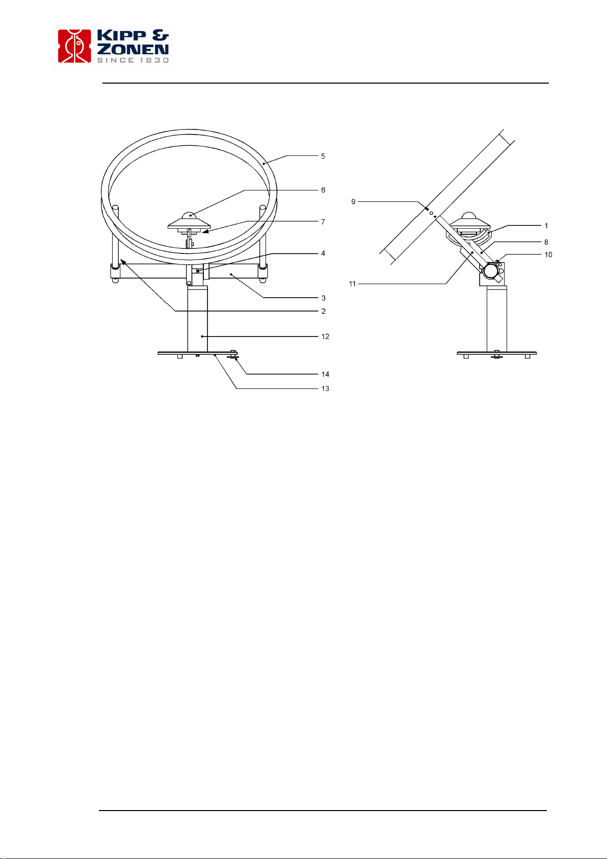
figure 1. the different parts of the shadow ring CM 121B
1 sector (including sight)
2 scale on the sliding bar (point of readout is indicated)
3 crossbar
4 securing bolt for the crossbar to the pyranometer support
5 shadow ring
6 pyranometer (normally not included in delivery)
7 spirit level of the pyranometer
8 pyranometer support
9 screws for attachment of the sliding bar to the shadow ring
10 fixing screws for the sliding bars
11 sliding bar
12 pillar
13 base
14 leveling screw for the base
8
Instruction manual CM 121
Page 10

2. UNPACKING AND ASSEMBLING
2.2 CM 121C
Packed in the CM 121C transport box are the same items as with the CM 121B plus:
z CV 2 adapter
z Two spacers
z Two cap screws M6 x 10
z Two cap screws M5 x 16
After removing the ties with which the items are connected to the transport box, the shadow ring can
easily be assembled.
z Place the pillar in between the base and the crossbar, using the thread
z Place the CV 2 adapter (see figure 1.2)
z Place the shadow ring on its sliding bars using two screws
z Insert the sliding bars in the crossbar. The correct way is when the pyranometer
sensor with CV 2 can be positioned along the axis of the ring
Caution before you start mounting the CM 121C you have to secure the base a surface
otherwise the CM 121C can fall over.
Caution: Please note that the screw that connects the pyranometer support with the crossbar
must never be touched because it defines the position of the pyranometer sector relative
to the sliding bars and the shadow ring. The sector must be in the center of the ring and
this is adjusted in the factory. The particular screw is protected by a cap.
Instruction manual CM 121
9
Page 11
2. UNPACKING AND ASSEMBLING
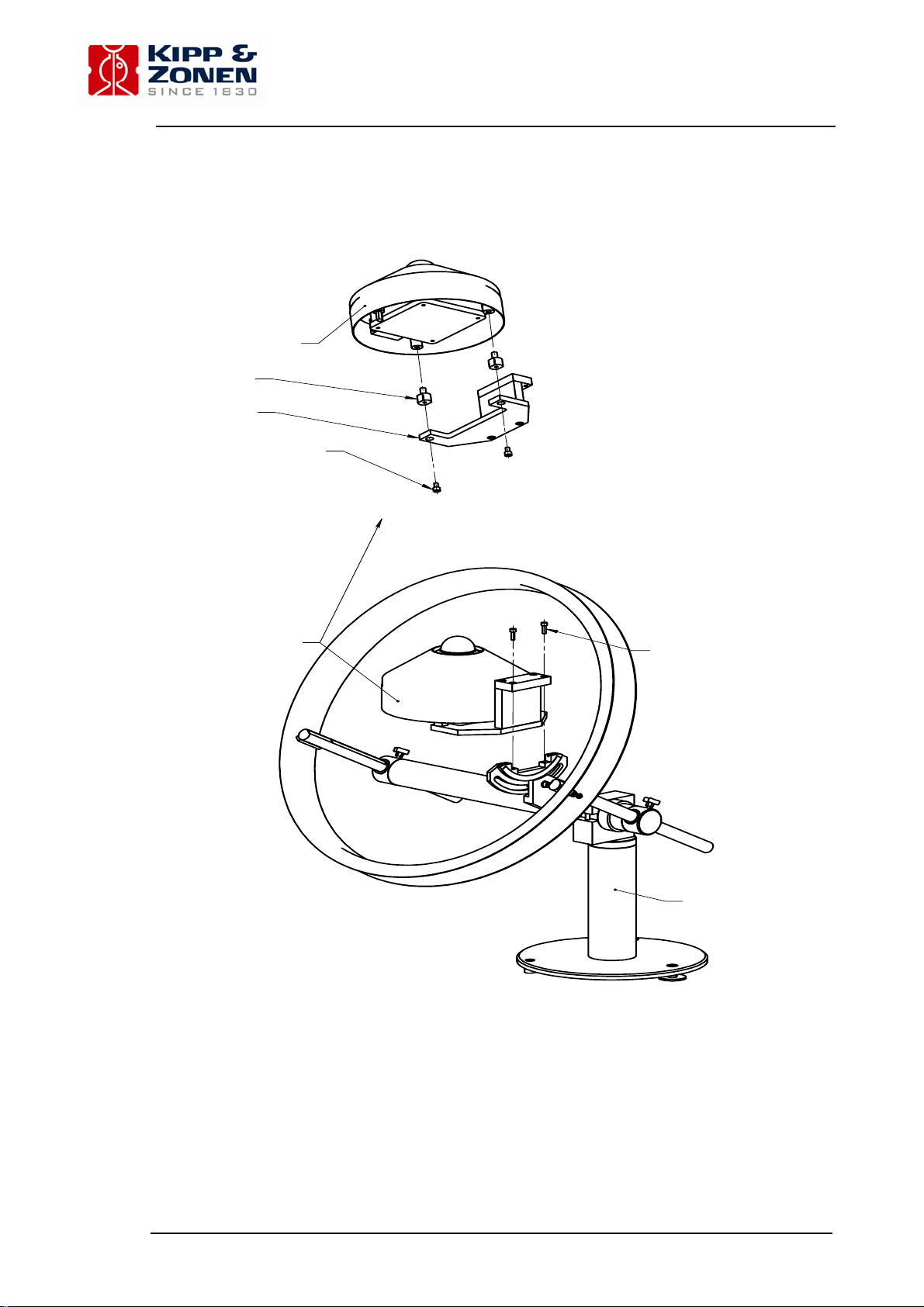
CV2
Remove
adjustable feet (2x)
Spacer (2x)
CV2 adapter
M6 x 10 ca p screw (2x)
CV2 + C V 2 adapter
Installation drawing CV2 + CM 121B
Docum ent number : 535-0346700-40
figure 1.2 the extra parts for the CM 121C and mounting instructions
M5 x 1 6 cap screw (2x)
CM 121B
10
Instruction manual CM 121
Page 12

3. PRINCIPLES & SPECIFICATIONS
3. PRINCIPLES & SPECIFICATIONS
3.1 Theory
The objective of the shadow ring is to intercept the direct radiation coming to the pyranometer from
the sun during the whole day without readjustment. Therefore the shadow ring must satisfy the
following requirements. See also the schematic representation (fig. 2).
z Once installed, the axis of the shadow ring must be always parallel to the polar-axis. In
consequence the angle between shadow ring axis and horizontal should be equal to the
latitude of the observation site.
z The shadow ring must be able to shift along the shadow ring axis relative to the pyranometer
and in this way be adjusted to the sun's changes in declination during the year.
z Within the shadow ring construction the pyranometer must be positioned with its sensor on
the shadow ring axis.
figure 2 schematic representation of the CM 121B on earth.
Also it is shown that the sliding bar setting is a function of the solar declination.
Instruction manual CM 121
11
Page 13

3. PRINCIPLES & SPECIFICATIONS
3.2 Construction
The crossbar is one of the main parts of CM 121B. By rotating the crossbar the angle between
shadow ring axis and horizontal earth surface can be set for the particular location. This is an
operation that needs to be performed only once for installation at a certain location. The pyranometer support is fixed to the crossbar, so the sensor stays in the center of the ring no matter the tilt
angle of the ring. For getting the pyranometer in the horizontal position, the so-called sector can be
rotated. See fig. 1.
With the sliding bars the shadow ring can shift along its axis. For this the fixing screws need temporarily to be unscrewed.
The normal situation is that the pyranometer is placed in the horizontal position. However, the
sector allows the pyranometer to rotate while keeping the sensor on the same position relative to
the ring, so that it is possible to mount the pyranometer in a tilted position along the north south
axis.
Measurement of the diffuse radiation on a plane tilted to the south or north is now possible, a
feature especially attractive in the application of solar collector testing.
For a site on latitude B the tilt range is B degrees to the equator and 90-B degrees to the nearest
pole.
3.3 Specifications
Material Anodized Aluminum of seawater proof quality,
Stainless steel
Weight incl. pyranometer CM 11 5.8 kg
Mounting base See figure 5
Ring outer diameter 620 mm.
Ring width 55 mm.
Ring width/ring radius ratio 0.185
View angle (The apparent width of the
ring as seen from the pyranometer) 10.6
0
U-profile shadow ring defines the accuracy of the view angle
constant within ± 2%
12
Instruction manual CM 121
Page 14

3. PRINCIPLES & SPECIFICATIONS
Instruction manual CM 121
13
Page 15

4. MOUNTING AND ALIGNMENT
4. MOUNTING AND ALIGNMENT
4.1 Introduction
The CM 121B can be mounted on any surface that is within one degree horizontal. It can also be
mounted on a tilted plane, if that plane faces south or north within 1/4 degree.
As explained in the previous chapter, the CM 121B has to be aligned north-south and the sliding
bars must be tilted and brought parallel to the polar axis. These two steps are described below.
Please mind that it is necessary to perform the north south alignment before the tilting of the sliding
bars, because it might be necessary to change the tilting during the north south alignment.
4.2 North-south alignment (one time installation)
The shadow ring has to be aligned to the north south axis. The preferred method to set the orientation is by observing the sun at 12.00 True Solar Time (= Local Apparent Time). This is the moment
when the sun is exactly south or north, a quite different time than 12.00 local clock or civil time. The
True Solar Time can be obtained from an astronomic observatory or taking the time in between
sunrise and sunset from the newspaper. For orienting the CM 121B at the sun, there is a groove
made in two separate metal sections of the sector. The sector can be oriented such that this groove
is aimed at the sun. The groove can be used as a sight (see fig.4). When the solar beam that
passes the first groove can also pass the second groove, the CM 121 is supposed to be aligned
with the sun. It is realized that close to the equator, this method looses its validity, and one has to
rely more on geographic orientation.
Caution: Please mind that for proper positioning of the pyranometer relative to the ring, the sector
is supposed to be fixed with its lower curved surface in direct contact with the upper
curved surface of the pyranometer support.
z Wait for a moment that the sun is shining.
z Direct the CM 121B roughly north-south using a map or compass. If possible it can be
recommended to use the sight for optimal orientation. Please note that if the sliding bar angle
is approximately correct (see next paragraph), the highest point of the ring should be pointing
south if the site is on the northern hemisphere, it should be pointing north if the site is in the
southern hemisphere. (see figure 4). Please note that close to the equator the orientation by
compass and subsequent correction by looking at sunrise and sunset performance can be
preferred.
z Now start the real alignment procedure:
z Unscrew the fixing screws of the sliding bars
z Put the shadow ring in a low position so that the sector is not shaded.
z Set the base of the CM 121B horizontal using a level. Do not fasten it.
z Loosen the pyranometer sector so that it can be rotated, changing its tilt angle, loosen the
securing bolt of the crossbar.
z Wait for solar noon.
z At solar noon, aim the sight on the pyranometer support exactly at the sun, keeping the
CM 121B base in the horizontal position, if necessary turning the CM 121B around its pillar
axis, turning the pyranometer sector and the crossbar in the north-south plane, changing its
tilt angle. The sight for doing the exact positioning consists of two grooves in the sector (see
above or fig.4).
z Rotate the sector and the whole CM 121 until the sights coincide with the centre of the sun
disc at 12.00 True Solar Time. Mind that the sun disc is moving 1/4 degree per minute along
the sky. The sun disc itself subtends half a degree.
z Fix the shadow ring base
z Install the pyranometer. Please note that installation of the pyranometer requires removal of
the levelling screws of the pyranometer. One can let the fixed foot stay on the pyranometer.
z Please mind that for proper positioning of the pyranometer relative to the ring, the sector is
supposed to be fixed with its lower curved surface in direct contact with the upper curved
surface of the pyranometer support.
z Perform the procedure for tilting of the sliding bars (paragraph 4.3)
z Elevate the shadow ring along the sliding bars so that it shades the pyranometer sensor
z Check if the elevation is conforming the sliding bar scale pointer as indicated in the table
14
Instruction manual CM 121
Page 16

4. MOUNTING AND ALIGNMENT
z Check the next sunrise and sunset if the dome is still shaded. If not, note if the change
between sunrise and sunset is symmetrical, and make corrections.
z For permanent installation it is recommended to secure the position of the shadow ring by
connecting its base to a solid underground. Figure 5 can be used for finding the proper
position for clamps or bolts.
figure 3. schematic view of the installation of CM 121B in several situations
Instruction manual CM 121
15
Page 17

4. MOUNTING AND ALIGNMENT
figure 4. set up to align the sight in the sector with the sun at 12.00 True Solar Time
figure 5. dimensions of the CM 121B base
16
Instruction manual CM 121
Page 18

4. MOUNTING AND ALIGNMENT
4.3 Tilting of the sliding bars (one time installation)
The purpose of this step is to bring the sliding bars parallel to the polar axis. This can be done by
rotating the crossbar after having unscrewed the securing bolt and relocking it in the required tilted
position.
When correctly aligned the angle between sliding bars and the horizontal should equal the geographical latitude. See figure 2. This procedure has to be performed only once, because it depends only
on the latitude of the site.
An accuracy of 1/4 degree is sufficient.
z Establish the latitude of the site
z Rotate the sector until the scale on the sector indicates the latitude of the
observation site
z Secure the sector by tightening the bolt
z Unlock the securing bolt of the crossbar
z Install the pyranometer
z Please mind that for proper positioning of the pyranometer relative to the ring, the
sector is supposed to be fixed with its lower curved surface in direct contact with
the upper curved surface of the pyranometer support.
z Rotate the crossbar until the pyranometer is horizontal again (look at the spirit
level of the pyranometer). By this rotation and by adjustment of the levelling
screw at the foot, the bubble of the spirit level can be completely leveled.
z Tighten the securing bolt of the crossbar again and fasten the foot to the
foundation.
Caution. Never unscrew the pyranometer support from the crossbar. In case such unscrewing
should have occurred, the support has to be aligned again in the following way. Set the
sector in position 90
0
. Set the ring horizontal with a level. Turn the support around the
crossbar until the pyranometer is in horizontal position as well (look at spirit level). Fix the
support to the crossbar.
Instruction manual CM 121
17
Page 19

4. MOUNTING AND ALIGNMENT
4.4 Setting of the shadow ring sliding bars (regular servicing procedure)
The correct shadow ring position is a function of the declination of the sun and it varies across the
year.
The only thing that needs to be done to readjust the position of the ring is to set the sliding bars. A
readjustment is necessary only after a few days. A regular schedule would require redjustment
every two days. However, in most seasons a longer time interval between adjustments is possible.
This can be seen in the table in 5.2.
z Unscrew the fixing screws of the sliding bars.
z Set the sliding bars using the sun or the table of 5.2. On clear days the setting of
the ring can be done by observing the shadow of the ring on the pyranometer. If
correctly aligned the outer dome of the pyranometer must be completely shaded.
(The dome shadow on the white screen is covered by the ring shadow.) On
cloudy days the ring can be set according to the date with the aid of the scale on
the sliding bars and the table of settings. See table 1 of 5.2 lowest row. The
relevant figure must be read off at upper side of the crossbar, see figure 1.
Please mind that the scale has two sections, centered around zero. At positive
declinations of the sun (21 March-23 Sept.) the part of the scale that is used must
be in the southern or lower part of the scale. At negative declinations of the sun
(23 Sept.-21 March) the part of the scale that is used must be in the northern or
higher part of the scale. See figure 2. The figures for the sliding bar adjustment
in this row are derived with the formula L = 297 tan (D), in which D is the
declination of the sun. The values of declination and sliding bar setting
correspond with the date intervals in the same table.
z Relock the fixing screws
18
Instruction manual CM 121
Page 20

5. MEASUREMENT OF THE DIFFUSE SKY RADIATION
5. MEASUREMENT OF THE DIFFUSE SKY RADIATION
5.1. The shadow ring correction
A pyranometer equipped with a shadow ring is measuring the downward diffuse solar radiation as
received by a horizontal surface from a solid angle of 2π with the exception of the solid angle
subtended by the shadow ring.
To obtain an estimation of the radiation that would be received from the whole hemisphere if the
ring were not present, a correction must be introduced. Such a correction factor is a function of the
solid angle subtended by the ring part and the sliding bars of the CM 121B and their altitude above
the pyranometer horizon.
The special U-profile of the shadow ring offers the advantage that the intercepted circumsolar part
of the sky is far more constant during the year compared to an I-profile (flat) shadow band.
(Compare formula 6.8 and 6.9).
The correction presented here is for the case of uniform sky radiation. The intercepted part can
easily be calculated. A list with correction factors is supplied. See table 1 in 5.2.
It is possible to use more refined models, assuming a more realistic distribution of the radiation
across the sky, however it is difficult to indicate how much improvement can be attained doing this
as these models tend to depend on empirically obtained data. A brief discussion concerning this
problem is found on page 429 of the International Geophysical Year instruction manual 1958,
Pergamon Press, London, Paris, New York.
The table is arranged so that the correction factors for particular latitude are in one row. The factors
are computed for declinations of - 24
The declination and the date are related to each other. On the top and the bottom of the table there
is a row with the corresponding date intervals, the upper row for increasing declination, the lower
one for decreasing declination.
0
to + 240 with intervals of two degrees.
Instruction manual CM 121
19
Page 21

5. MEASUREMENT OF THE DIFFUSE SKY RADIATION
20
Instruction manual CM 121
Page 22

5. MEASUREMENT OF THE DIFFUSE SKY RADIATION
5.3 Diffuse sky radiation on a tilted plane
The correction factors are only valid for a pyranometer in the horizontal position.
However, for a pyranometer tilted T degrees to the south and on latitude B, the configuration of ring
and pyranometer is the same as for a horizontal pyranometer at latitude (B - T) degrees.
You can derive a list of correction factors for a tilted pyranometer from table 1 in 5.2, taking into
account that only part of the hemisphere is 'seen' by the pyranometer. However, this correction
does not take the effect of ground-reflected radiation into account. The correction for this is very
much dependant on local conditions and might vary throughout the day as a function of the solar
position, and throughout the year as a function of ground properties. Therefore this is the responsibility of the customer.
Instruction manual CM 121
21
Page 23

5. MEASUREMENT OF THE DIFFUSE SKY RADIATION
22
Instruction manual CM 121
Page 24

6. APPENDIX
6. APPENDIX
6.1 Theoretical derivation of the correction factor, for uniform sky radiation
The relation between the correction factor C and the intercepted part S of the downward
component of the sky radiation is
C = 1 / (1 -S) (6.1)
S can be expressed in the view angle V of the ring, the sun's declination D and the latitude B of the
observation site.
be the angle between the sun at sunrise (or at sunset) and the sun at true noon in the plane
Let U
0
of the ring.
is computed with the formula:
U
0
cosU
Let us consider a part of the ring subtending a solid angle V.dU as seen from point M, the center of
the ring, and as seen from the pyranometer of
V . cosD . dU (6.3)
V is assumed to be constant within the range of D, due to the special U-profile shadow ring.
Not every part of the ring equally affects the total downward component of the sky. This is because
this component is proportional with the cosine of its zenith angle Z. Radiation with a zenith angle Z
within this solid angle causes a downward component
L . V . cosD . cosZ . dU (6.4)
L is the radiance (= brightness) of the sky in W/m2 sr. L is assumed to be uniform over the
complete sky. So the complete ring part above the horizon intercepts a downward cornponent
2L . V . cosD .
Z can be expressed in the declination D, latitude B and time (by the hour angle U) with the
formula
cosZ = sinB . sin D + cosB . cosD . cosU (6.6)
After integrating we find the total intercepted downward radiation to be
2L . V . cosD . (U
The total irradiance of a horizontal surface by a sky with radiance L (W/m2 sr) is L (W/m2).
The intercepted part S of the sky radiation therefore is
S = 2V . cosD . (U
From this formula the list of correction factors is computed taking into account formula (6.2)
and (6.1) and V = 0.185 rad. Mind that U
Actually V varies within 2% in dependence of the declination D but this gives only rise to an error
less than ± 0.5% in the calculated correction factors.
= - tanB . tan D (6.2)
0
U0
I
cosZ . dU (6.5)
0
. sinB . sinD + sinU0 . cosB . cosD) (6.7)
0
. sinB . sinD + sinU0 . cosB . cosD) / π (6.8)
0
is in radians.
0
Instruction manual CM 121
23
Page 25

6. APPENDIX
The influence of the sliding bar parts rising above the horizon is neglected.
To compare: the formula for a flat shadow band is
S = 2W . cos3 . D . (U
. sinB . sinD + sinU0 . cosB . cosD) / π. R (6.9)
0
W is the ring width and R is the ring radius. A comparison is shown in figure 6.
figure 6 the view angle of the U-profile shadow ring as a function of the solar declination, in
comparison to a conventional flat shadow band. It is shown that the CM 121B has superior
performance, as a result less seasonally variation of errors.
24
Instruction manual CM 121
Page 26

6. APPENDIX
Instruction manual CM 121
25
Page 27

Our customer support remains at your disposal for any maintenance or repair, calibration,
supplies and spares.
Für Servicearbeiten und Kalibrierung, Verbrauchsmaterial und Ersatzteile steht Ihnen unsere
Customer Support Abteilung zur Verfügung.
Notre service 'Support Clientèle' reste à votre entière disposition pour tout problème de
maintenance, réparation ou d'étalonnage ainsi que pour les accessoires et pièces de rechange.
Nuestro apoyo del cliente se queda a su disposición para cualquier mantenimiento o la
reparación, la calibración, los suministros y reserva.
HEAD OFFIC E
Kipp & Zonen B.V.
Delftechpark 36, 2628 XH Delft
P.O. Box 507, 2600 AM Delft
The Netherlands
T: +31 (0) 15 2755 210
F: +31 (0) 15 2620 351
info@kippzonen.com
SALES OFFICES
Kipp & Zonen France S.A.R.L.
7 Avenue Clément Ader
ZA Ponroy - Bâtiment M
94420 Le Plessis Trévise
France
Kipp & Zonen Asia Pacific Pte. Ltd.
81 Clemenceau Avenue
#04-15/16 UE Square
Singapore 239917
Kipp & Zonen USA Inc.
125 Wilbur Place
Bohemia
NY 11716
United States of America
Go to www.kippzonen.com for your local distributor or contact your local sales office
T:
+33 (0) 1 49 62 41 04
F: +33 (0) 1 49 62 41 02
kipp.france@kippzonen.com
T: +65 (0) 6735 5033
F: +65 (0) 6735 8019
kipp.singapore@kippzonen.com
T: +1 (0) 631 589 2065
F: +1 (0) 631 589 2068
kipp.usa@kippzonen.com
Passion for Precision
 Loading...