

Page 1
CHP 1
Pyrheliometer
Instruction Manual
Page 2
IMPORTANT USER INFORMATION
Reading this entire manual is recommended for full understanding of the use of this product.
Should you have any comments on this manual we will be pleased to receive them at:
Kipp & Zonen B.V.
Delftechpark 36, 2628 XH Delft, the Netherlands
or P.O. Box 507, 2600 AM Delft, the Netherlands
T: +31 (0)15 2755 210
F: +31 (0)15 2620 351
info@kippzonen.com
www.kippzonen.com
Kipp & Zonen reserves the right to make changes to the specifications without prior notice.
WARRANTY AND LIABILITY
Kipp & Zonen guarantees that the product delivered has been thoroughly tested to ensure that it meets its
published specifications. The warranty included in the conditions of delivery is valid only if the product has been
installed and used according to the instructions supplied by Kipp & Zonen.
Kipp & Zonen shall in no event be liable for incidental or consequential damages, including without limitation, lost
profits, loss of income, loss of business opportunities, loss of use and other related exposures, however used,
rising from the faulty and incorrect use of the product. User made modifications can affect the validity of the CE
declaration.
COPYRIGHT© 2008 Kipp & Zonen B.V.
All rights are reserved. No part of this publication may be reproduced, stored in a retrieval system or transmitted in
any form or by any means, without permission in written form from the company.
Manual version: 0811
2
Page 3

DECLARATION OF CONFORMITY
According to EC guideline 89/336/EEC
We Kipp & Zonen B.V.
Delftechpark 36
2628 XH Delft
The Netherlands
Declare under our sole responsibility that the product
Type: CHP 1
Name: Pyrheliometer
To which this declaration relates is in conformity with the following standards
Imissions EN 50082-1 Group standard
IEC 100-4-2 IEC 801-2 8 kV
IEC 100-4-3 IEC 801-3 3 V/m
IEC 100-4-4 IEC 801-4 1 kV
Emissions EN 50081-1 Group standard
EN 55022
Following the provisions of the directive:
B.A.H. Dieterink
President
KIPP & ZONEN B.V.
3
Page 4

TABLE OF CONTENTS
IMPORTANT USER INFORMATION........................................................................................................................................ 2
WARRANTY AND LIABILITY .....................................................................................................................................................2
DECLARATION OF CONFORMITY .........................................................................................................................................3
TABLE OF CONTENTS................................................................................................................................................................. 4
INTRODUCTION ............................................................................................................................................................................ 5
1 INSTALLATION AND OPERATION................................................................................................................................ 6
1.1 Delivery................................................................................................................................... 6
1.2 Contents of delivery ................................................................................................................ 6
1.3 Mechanical installation ............................................................................................................ 6
1.4 Electrical installation ............................................................................................................... 7
2 OPERATION............................................................................................................................................................................ 8
2.1 Measurement of direct solar radiation..................................................................................... 8
2.2 Measurement of instrument temperature ................................................................................ 8
3 MAINTENANCE ..................................................................................................................................................................... 9
4 PRINCIPLE COMPONENTS OF PYRHELIOMETERS.............................................................................................. 10
4.1 Window ................................................................................................................................. 10
4.2 Detector ................................................................................................................................ 10
4.3 Housing ................................................................................................................................ 10
4.4 Drying cartridge .................................................................................................................... 10
4.5 Cable and connector .............................................................................................................10
5 PYRHELIOMETER PHYSICAL PROPERTIES............................................................................................................. 11
5.1 Spectral range ....................................................................................................................... 11
5.2 Sensitivity.............................................................................................................................. 11
5.3 Impedance ............................................................................................................................ 11
5.4 Response time ...................................................................................................................... 11
5.5 Operating temperature.......................................................................................................... 11
5.6 Field of view .......................................................................................................................... 12
5.7 Environmental ....................................................................................................................... 12
6 MEASUREMENT ACCURACY ........................................................................................................................................ 13
6.1 Non linearity ......................................................................................................................... 13
6.2 Temperature dependence...................................................................................................... 13
6.3 Zero offset B ......................................................................................................................... 13
6.4 Non-stability.......................................................................................................................... 14
6.5 Spectral selectivity................................................................................................................. 14
7 CALIBRATION..................................................................................................................................................................... 15
7.1 Calibration principle.............................................................................................................. 15
7.2 Calibration procedure at Kipp & Zonen.................................................................................. 15
7.3 Traceability to world radiometric reference ........................................................................... 15
8 RECALIBRATION ............................................................................................................................................................... 16
9 FREQUENTLY ASKED QUESTIONS ............................................................................................................................ 16
10 TROUBLE SHOOTING ................................................................................................................................................. 16
APPENDIX I RADIOMETRIC TERMINOLOGY .................................................................................................................. 17
APPENDIX II 10K THERMISTOR SPECIFICATIONS ...................................................................................................... 18
APPENDIX III PT-100 SPECIFICATIONS ............................................................................................................................ 19
APPENDIX IV MAIN SPECIFICATIONS ............................................................................................................................... 20
APPENDIX V LIST OF WORLD AND REGIONAL RADIATION CENTRES .............................................................. 21
APPENDIX VI RECALIBRATION SERVICE ......................................................................................................................... 22
4
Page 5

INTRODUCTION
Dear customer, thank you for purchasing a Kipp & Zonen instrument. Please read this manual and the separate
instruction sheet for a full understanding of the use of your pyrheliometer.
The pyrheliometer CHP 1 is designed to measure the irradiance which results from the radiant flux from a solid
angle of 5 °.
According to International Standard ISO 9060 and the World Meteorological Organization (WMO) a pyrheliometer is
the designated type of instrument for the measurement of direct solar radiation. The CHP 1 pyrheliometer is
compliant with the “First Class” class specified by the international standards.
This manual, together with the instruction sheet, gives information related to installation, maintenance, calibration,
product specifications and applications of the CHP 1 pyrheliometer.
If any questions should remain, please feel free to contact your Kipp & Zonen dealer or e-mail info@kippzonen.com
For information about other Kipp & Zonen products or to check for any update of this manual, go to
www.kippzonen.com
5
Page 6

1 INSTALLATION AND OPERATION
1.1 Delivery
Check the contents of the shipment for completeness (see below) and note whether any damage has occurred
during transport. If there is damage, a claim should be filed with the carrier immediately. In this case, or if the
contents are incomplete, your dealer should be notified in order to facilitate the repair or replacement of the
instrument.
1.2 Contents of delivery
Pyrheliometer
Rain screen
Cable with connector
Test reports
Instruction sheet
2x Desiccant bags
Product documentation CD
Although the CHP 1 is weatherproof and suitable for harsh environmental conditions, they have some delicate
mechanical parts. Please keep the original packaging for safe transport of the radiometer to the measurement site
or for use when returning the radiometer for calibration.
The calibration certificate supplied with the instrument is valid for 1 year from the date of first use by the customer,
subject to the variations in performance due to specific operating conditions that are given in the instrument
specifications. The calibration certificate is dated relative to the time of manufacture, or recalibration, but the
instrument does not undergo any sensitivity changes when kept in the original packing and not exposed to light.
From the moment the instrument is taken from its packaging and exposed to irradiance the sensitivity will deviate
slightly with time. See the 'non-stability' performance (maximum sensitivity change per year) given in the radiometer
specification list.
1.3 Mechanical installation
The mechanical installation will be explained in the next paragraphs.
Figure 1: Dimensional drawing CHP 1
For installation on the Kipp & Zonen trackers 2AP and Solys2, please consult the manual of the tracker.
6
Page 7
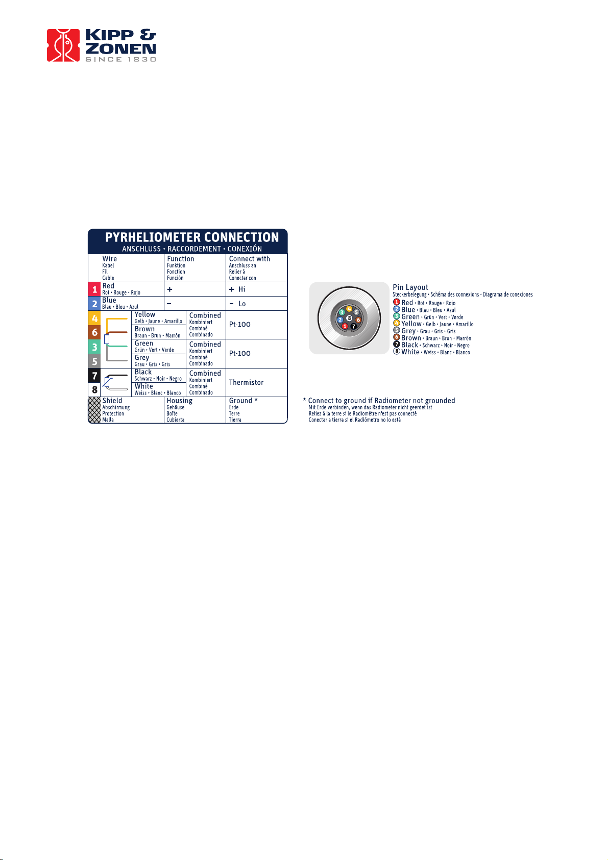
1.4 Electrical installation
As standard the CHP 1 is supplied with a waterproof connector pre-wired to 10 m cable with a number of leads and
a shield covered with a black sleeve. The number of connector pins and cable leads depends upon the model of
pyrheliometer and whether a temperature sensor is fitted (and which type). The colour code of the wires and the
connector pin numbers are shown on the instruction sheet. Longer cables are available as options.
The shield of the cable is connected to the aluminum radiometer housing through the connector body. The shield at
the cable end may be connected to ground at the readout equipment. Lightning can induce high voltages in the
shield but these will be led off at the pyrheliometer and data logger.
Kipp & Zonen pyrheliometer cables are of low noise type, but bending the cable produces small voltage spikes, a
tribo-electric and capacitance effect. Therefore, the cable must be firmly secured to minimize spurious responses
during stormy weather.
The impedance of the readout equipment loads the temperature compensation circuit and the thermopile. It can
increase the temperature dependency of the pyrheliometer. The sensitivity is affected more than 0.1 % when the
load resistance is less than 100 kΩ. For this reason we recommend the use of readout equipment with an input
impedance of 1 MΩ or more. The solar integrators, data loggers and chart recorders from Kipp & Zonen meet these
requirements.
Long cables may be used, but the cable resistance must be smaller than 0.1 % of the impedance of the readout
equipment. It is evident that the use of attenuator circuits to modify the calibration factor is not recommended
because the temperature response will also be affected.
A high input bias current at the readout equipment can produce several micro-Volts across the impedance of the
pyrheliometer and cable. The zero offset can be verified by replacing the pyrheliometer impedance at the readout
equipment input terminals with a resistor.
The pyrheliometer can also be connected to a computer or data acquisition system. A low voltage analogue input
must be available. The resolution of the Analogue-to-Digital Converter (ADC) must allow a system sensitivity of
about 1 bit per W/m
pyrheliometers exhibit offsets up to ± 2 W/m
2
. More resolution is not necessary during outdoor solar radiation measurements, because
2
due to lack of thermal equilibrium.
For amplification of the pyrheliometer signal Kipp & Zonen offers the AMPBOX signal amplifier. This amplifier will
convert the micro-Volt output from the pyrheliometer into a standard 4 – 20 mA signal. The use of the AMPBOX
amplifier is recommended for applications with long cables (> 100 m), electrically noisy environments or data
loggers with a current-loop input. The AMPBOX can be factory adjusted to suit the sensitivity of an individual
radiometer to produce a defined range, typically 4 – 20 mA represents 0 – 1600 W/m
2
.
7
Page 8

2 OPERATION
2.1 Measurement of direct solar radiation
After completing the installation the pyrheliometer will be ready for operation.
The irradiance value (E↓Solar) can be simply calculated by dividing the output signal (Uemf) of the pyrheliometer by
its sensitivity (Sensitivity) as shown in Equation 1. For calculation of the direct solar irradiance the following formula
must be applied:
U
emf
E
Equation 1: Calculation of solar radiation
Where:
E
DirectSolar
= Output of radiometer [μV]
U
emf
S = Sensitivity of radiometer [μV/W/m
To be certain that the quality of the data is of a high standard, care must be taken with daily maintenance of the
radiometer. Once a voltage measurement is taken, nothing can be done to retrospectively improve the quality of
that measurement.
=
rDirectSola
S
= Solar radiation [W/m2]
2
]
2.2 Measurement of instrument temperature
Inside the detector assembly a Pt-100 (Class A) and 10kΩ thermistor are placed to provide the detector temperature.
The location of these temperature sensors is shown in Figure 2.
Pt-100
Detector
10k Thermistor
Figure 2: Position of temperature sensors inside the CHP 1 detector assembly
The temperature of the Pt-100 and 10kΩ thermistor can be derived using Equation 2 and Equation 3
T
=
T
Temperature
[”C]
= ResistanceR =
Equation 2: Temperature vs Thermistor Resistance Equation 3: Temperature vs Pt-100 resistance
Detector assembly
-
R
+ 1
T
=
100
8
Page 9

3 MAINTENANCE
Once installed the pyrheliometer needs little maintenance. The window must be cleaned and inspected regularly,
ideally every morning.
A periodic check is to ensure that the silica gel desiccant is still coloured orange. When the yellow silica gel in the
drying cartridge is turned completely transparent (normally after several months), it must be replaced by fresh silica
gel as supplied in the small refill packs. The content of one pack is sufficient for one complete refill. At the same
time check that the radiometer mounting is secure and that the cable is in good condition.
Some tips when changing the desiccant:
Make sure the surfaces of the radiometer and the drying cartridge that touch the rubber o-ring are clean (corrosion
can do a lot of harm here and dirt, in combination with water, can cause this);
The rubber o-ring is coated with a silicon grease to improve the seal. If the rubber o-ring looks dry apply some
grease to it (Vaseline will also do);
Check that the drying cartridge is tightly threaded into the radiometer body.
It is very difficult to make the radiometers hermetically sealed; so, due to pressure differences between the inside
and the outside of the instrument, there will always be some exchange of (humid) air.
The radiometer sensitivity changes with time and with exposure to radiation. Calibration every two years is advised.
Further information about Kipp & Zonen recalibration services can be found in Appendix VI.
9
Page 10

4 PRINCIPLE COMPONENTS OF PYRHELIOMETERS
The detector of the Kipp & Zonen CHP 1 pyrheliometer is based on a passive thermal sensing element called a
thermopile.
The thermopile responds to the total power absorbed by the black surface coating, which is a non-spectrally
selective paint, and warm up. The heat generated flows through a thermal resistance to the heat-sink (the
pyrheliometer body). The temperature difference across the thermal resistance of the detector is converted into a
voltage as a linear function of the absorbed solar irradiance.
A drying cartridge (dessicator) in the radiometer housing is filled with silica gel and prevents dew on the inner sides
of the windows, which can cool down considerably on clear windless nights.
4.1 Window
The window material of the pyrheliometer defines the spectral measurement range of the instrument. In general
about 97 – 98 % of the solar radiation spectrum will be transmitted through the window and will be absorbed by the
detector.
4.2 Detector
The thermopile sensing element is made up of a large number of thermocouple junction pairs connected electrically
in series. The absorption of thermal radiation by one of the thermocouple junctions, called the active (or ‘hot’)
junction, increases its temperature. The differential temperature between the active junction and a reference (‘cold’)
junction kept at a fixed temperature produces an electromotive force directly proportional to the differential
temperature created. This is a thermoelectric effect. The sensitivity of a pyrheliometer depends on the individual
physical properties of the thermopile and construction. The sensitivity of each thermopile is unique and therefore
each radiometer has unique calibration factor, even with the same radiometer model.
On the top surface of the sensor a black paint is deposited which has a very rough structure containing many microcavities that effectively ‘’trap’’ more than 97 % of the incident radiation in a broad spectral range. Furthermore, the
spectral selectivity is less than 2 %. This means that within the spectral range of the pyrheliometer, the absorption
for each wavelength is equal to within 2 %. The black painted sensing element forms the detector. Considering the
long-term stability of the instrument, the black paint is one of the most crucial and delicate parts of the
pyrheliometer. Kipp & Zonen black paint gives the best possible stability over a long period of time under all
meteorological circumstances.
4.3 Housing
The radiometer housing accommodates all fundamental pyrheliometer parts. The anodized Aluminum parts are
light weight and give a high mechanical and thermal stability to the instrument. Due to its fine mechanical
construction all pyrheliometers are virtually sealed and comply with the international standard IP 67.
4.4 Drying cartridge
In case moisture enters the radiometer body the silica-gel desiccant regulates the humidity level inside the
pyrheliometer. Initially the desiccant will have an orange color. After some time it becomes saturated with moisture
and the colour will change to become clear (transparent). At this time the contents of the drying cartridge should be
replaced with fresh, unsaturated orange colored desiccant as soon as possible. Replacement desiccant is available
through Kipp & Zonen distributors.
4.5 Cable and connector
For ease of installation and replacement during recalibration of the radiometer, the CHP 1 is provided with a
weather proof signal cable connector.
Kipp & Zonen radiometers use a custom-made cable that is selected as a low noise type particularly suited to handle
the low voltage output of the thermopile or of a temperature sensor.
The shield of the cable is connected to the metal body of the connector and preferably should be connected to
ground at the readout equipment. Cables come pre-wired to the connector plug in a range of lengths.
10
Page 11

5 PYRHELIOMETER PHYSICAL PROPERTIES
In this chapter the principal physical characteristics of the CHP 1 pyrheliometer are given.
5.1 Spectral range
The spectrum of the solar radiation reaching the Earth’s surface is in the wavelength range between 280 nm and
4000 nm, extending from ultraviolet (UV) to the far infrared (FIR) as shown in Figure 9. Due to the excellent physical
properties of the quartz window and black absorber paint, the Kipp & Zonen CHP 1 pyrheliometer is equally
sensitive in a wide spectral range. 97-98 % of the total energy will be absorbed by the thermal detector.
1
Typical
0.8
window
0.6
0.4
Transmittance [Arbitrary units]
0.2
0
200 700 1200 1700 2200 2700 3200 3700
Wavelength [nm]
Figure 3: Solar irradiance spectrum at the Earth’s surface and pyrheliometer response
Typical Solar
spectrum
5.2 Sensitivity
The radiometer thermopile sensitivity is mainly determined by the physical properties of the detector itself. The
thermoelectric power, thermal conductivity of the junctions and the overall dimensions of the sensing element are
related to its sensitivity.
5.3 Impedance
The radiometer impedance is defined as the total electrical impedance at the radiometer output connector fitted to
the housing. It arises from the electrical resistance in the thermal junctions, wires and passive electronics within the
radiometer.
5.4 Response time
Any measuring device requires a certain time to react to a change in the parameter being measured. The radiometer
requires time to respond to change in the incident radiation. The response time is normally quoted as the time for
the output to reach 95 % (sometimes 63 %) of the final value following a step-change in irradiance. It is determined
by the physical properties of the thermopile and the radiometer construction. The CHP 1 has a fast response, which
makes them suitable for measuring solar radiation under variable weather conditions.
5.5 Operating temperature
The operating temperature range of the radiometer is determined by the physical properties of the individual parts.
Within the specified temperature range Kipp & Zonen radiometers can be operated safely. Outside this temperature
range special precautions should be taken to prevent any physical damage or performance loss of the radiometer.
Please contact your distributor for further information regarding operation in unusually harsh temperature
conditions.
11
Page 12

5.6 Field of view
Figure 4 shows the pyrheliometers optical construction.
Figure 4: Optical construction
The beam of light that reaches the detector is limited by the field and aperture stop. The slope, opening and limit
angles are determined by R, r and L. The distance x is negligible.
For the CHP 1 the full opening angle is 5 °, the slope angle is 1 °. The sun, as seen from the detector, occupies a
solid angle of 0.5 °. A 100 % response can be expected only if the sun is entirely within the slope angle. This is the
case when tracking accuracy is better than slope angle minus half the solar angle.
Concluding, tracking accuracy should be within 0.75 ° of ideal.
5.7 Environmental
The CHP 1 pyrheliometer is designed for outdoor use under all expected weather conditions. The radiometers
comply with IP 67 and their solid mechanical construction is suitable to be used under all environmental conditions
within the specified ranges.
12
Page 13

6 MEASUREMENT ACCURACY
When a pyrheliometer is in operation, its performance is correlated to a number of parameters, such as
temperature, level of irradiance etc. Normally, the supplied sensitivity figure is used to calculate the irradiances. If
the conditions differ significantly from calibration conditions, uncertainty in the calculated irradiances must be
expected.
For a first class pyrheliometer the WMO expects maximum errors in the hourly radiation totals of 3 %. In the daily
total an error of 2 % is expected, because some response variations cancel each other out if the integration period is
long. Kipp & Zonen expects maximum uncertainty of 2 % for hourly totals and 1% for daily totals for the CHP 1
pyrheliometer.
For the CHP 1 the effect of each parameter on the sensitivity can be shown separately.
6.1 Non linearity
The non-linearity error, the sensitivity variation with irradiance is shown in Figure 5 for a range from 0 to
1000aW/m
2
referred to the calibration at 500 W/m2.
Figure 5: Non-linearity sensitivity variation of a CHP 1
6.2 Temperature dependence
The temperature dependence of the sensitivity is a function of the individual CHP 1. For a given instrument the
response lies in the region between the curved lines in Figure 6. The temperature dependence of each pyrheliometer
is characterized and supplied with the instrument. Each CHP 1 has built-in temperature sensors to allow corrections
to be applied if required.
Figure 6: Typical temperature dependency of a CHP 1
6.3 Zero offset B
Proportionally to the ambient temperature the instrument temperature varies and causes heat currents inside the
instrument. This will cause an offset commonly called Zero Offset type B. It is quantified as the response in W/m
a 5 K/hr change in ambient temperature.
2
to
13
Page 14

6.4 Non-stability
This is the percentage change in sensitivity over a period of one year. This effect is mostly due to degradation by UV
radiation of the black absorber paint on the sensing element surface. Kipp & Zonen recommends recalibration every
two years. However, for quality assurance purposes some institutes, companies or networks may require more or
less frequent recalibration. Please read the chapter on the calibration procedure for pyrheliometers for more
information.
6.5 Spectral selectivity
Spectral selectivity is the variation of the window transmittance and absorption coefficient of the black detector
paint with wavelength and is commonly specified as a % of the mean value.
14
Page 15

7 CALIBRATION
7.1 Calibration principle
An ideal pyrheliometer gives voltage output that is proportional to the absolute irradiance level. This relationship
can be expressed as a constant ratio called ‘sensitivity’ (Sensitivity).
The sensitivity figure of a particular pyrheliometer is unique. It is determined in the manufacturer's laboratory by
comparison against a reference pyrheliometer of similar type. The reference pyrheliometer is calibrated outdoors
regularly at the World Radiation Centre (WRC) at Davos, Switzerland. The spectral content of the laboratory
calibration lamp differs from the outdoor solar spectrum at the World Radiation Centre. However, this has no
consequences for the transfer of calibration, because standard and test pyrheliometers have the same black coating
and windows.
The supplied sensitivity figure is valid for the following conditions:
An ambient temperature of +20 °C.
Normal incident radiation of 500 W/m
For any other condition the sensitivity figure can be used within uncertainty bands given in the specifications for
each model.
A summary of calibration methods is also found in the WMO guide of 1996.
2
.
7.2 Calibration procedure at Kipp & Zonen
At Kipp & Zonen, calibration is performed by indoor comparison with a reference instrument. The reference is not of
a higher standard classification. The comparison is made under a xenon lamp at an irradiance level of
approximately 500 W/m
2
. The reference has been calibrated at the World Radiation Centre. The accuracy of this
calibration is ± 0.5 %. ISO requests that each pyrheliometer, in order to obtain its classification, must periodically be
compared to a higher standard.
7.3 Traceability to world radiometric reference
Reference pyrheliometers, which are calibrated annually by the World Radiation Centre in Davos, are used for the
calibration of radiometers manufactured by Kipp & Zonen. The reference radiometers are fully characterized, i.e.
linearity, temperature dependence and directional response are recorded.
Kipp & Zonen keeps two reference radiometers for each radiometer model. These reference radiometers are sent
alternate years to WRC for calibration, so production and calibration in Delft can carry on without interruption.
15
Page 16

8 RECALIBRATION
Radiometer sensitivity changes with time and with exposure to radiation. Periodic calibration every two years is
advised.
Accurate calibrations can be done outdoors under clear conditions by comparison with a reference pyrheliometer.
Many national or regional weather services have calibration facilities. Their standard pyrheliometer is compared with
the World Radiometric Reference at Davos, Switzerland. This embodies several absolute cavity (black body)
pyrheliometers. Information about regional calibration centres can be found in appendix V.
9 FREQUENTLY ASKED QUESTIONS
The most frequently asked questions are listed in the FAQ section of our website at www.kippzonen.com
10 TROUBLE SHOOTING
The following contains a procedure for checking the instrument in case it appears that it does not function as it
should.
Output signal fails or shows improbable results:
• Check the wires are properly connected to the readout equipment.
• Check the instrument location. Are there any obstructions that cast a shadow on the window by blocking
the direct sun during some part of the day?
• Check the window, it should be clear and clean. If water is deposited on the inside, please change the
desiccant. If too much water is deposited internally the drying cartridge should be removed and the
instrument warmed to dry it.
• Check instrument impedance (see specifications for expected values).
• Check data logger or integrator offset by connecting a dummy load (100 Ohm resistor). This should give a
Any visible damage or malfunction should be reported to your distributor, who will suggest appropriate action.
“zero” reading.
• If water or ice is deposited on the window, clean it. Probably water droplets will evaporate in less than one
hour under sunlight.
16
Page 17

APPENDIX I RADIOMETRIC TERMINOLOGY
Term Explanation
Albedo The portion of incoming radiation which is reflected by a surface
Azimuth angle Angle in horizontal direction (0-360 °)
Angle of incidence Incident angle from zenith (vertical)
Cosine response Detector response according to the cosine law
Diffuse solar irradiance Solar radiation, scattered by water vapor, dust and other particles as
it passes through the atmosphere
Direct solar irradiance Radiation that has traveled a straight path from the sun
Global solar irradiance Total irradiance falling on a horizontal surface (Diffuse + Direct ⋅ cos α)
Irradiance Radiant flux density (W/m
Long-wave radiation Radiation with wavelengths > 4 μm and < 100 μm
Pyrheliometer Radiometer suitable to measure short-wave global radiation
Pyrgeometer Radiometer suitable to measure downward long-wave radiation
Pyrheliometer Radiometer suitable to measure direct irradiance
Short-wave radiation Radiation with wavelengths > 280 nm and < 4 μm
Thermopile Thermal detector made up of many thermocouple junctions
WMO World Meteorological Organisation
WRC World Radiation Center (in Davos, Switzerland)
WRR World Radiation Reference (standard radiation scale)
WSG World Standard Group (radiometer standards maintained in Davos)
Zenith angle Angle from zenith (0 °, vertical)
2
)
17
Page 18

APPENDIX II 10K THERMISTOR SPECIFICATIONS
YSI Thermistor 44031 - Resistance versus Temperature in °C
T
=
YSI 44031 Temperature vs. Resistance
Temperature
[˚C] [˚F]
-30 -22.0
-29 -20.2
-28 -18.4
-27 -16.6
-26 -14.8
-25 -13.0
-24 -11.2
-23 -9.4
-22 -7.6
-21 -5.8
-20 -4.0
-19 -2.2
-18 -0.4
-17 1.4
-16 3.2
-15 5.0
-14 6.8
-13 8.6
-12 10.4
-11 12.2
-10 14.0
-9 15.8
-8 17.6
-7 19.4
-6 21.2
-5 23.0
-4 24.8
-3 26.6
-2 28.4
-1 30.2
Resistance
[Ohm]
135,200
127,900
121,100
114,600
108,600
102,900
97,490
92,430
87,660
83,160
78,910
74,910
71,130
67,570
64,200
61,020
58,010
55,170
52,480
49,940
47,540
45,270
43,110
41,070
39,140
37,310
35,570
33,930
32,370
30,890
Temperature
[˚C] [˚F]
0 32.0
1 33.8
2 35.6
337.4
439.2
5 41.0
6 42.8
7 44.6
846.4
948.2
10 50.0
11 51.8
12 53.6
13 55.4
14 57.2
15 59.0
16 60.8
17 62.6
18 64.4
19 66.2
20 68.0
21 69.8
22 71.6
23 73.4
24 75.2
25 77.0
26 78.8
27 80.6
28 82.4
29 84.2
Resistance
[Ohm]
29,490
28,150
26,890
25,690
24,550
23,460
22,430
21,450
20,520
19,630
18,790
17,980
17,220
16,490
15,790
15,130
14,500
13,900
13,330
12,790
12,260
11,770
11,290
10,840
10,410
10,000
9,605
9,227
8,867
8,523
T
Temperature
[”C]
= ResistanceR =
Temperature
[˚C] [˚F]
30 86.0
31 87.8
32 89.6
33 91.4
34 93.2
35 95.0
36 96.8
37 98.6
38 100.4
39 102.2
40 104.0
41 105.8
42 107.6
43 109.4
44 111.2
45 113.0
46 114.8
47 116.6
48 118.4
49 120.2
50 122.0
51 123.8
52 125.6
53 127.4
54 129.2
55 131.0
56 132.8
57 134.6
58 136.4
59 138.2
Resistance
[Ohm]
8,194
7,880
7,579
7,291
7,016
6,752
6,500
6,258
6,026
5,805
5,592
5,389
5,193
5,006
4,827
4,655
4,489
4,331
4,179
4,033
3,893
3,758
3,629
3,504
3,385
3,270
3,160
3,054
2,952
2,854
18
Page 19

APPENDIX III PT-100 SPECIFICATIONS
Pt-100 - Resistance versus Temperature in ºC and ºF
-
R
+ 1
T
=
100
Pt-100 Temperature vs. Resistance
Temperature
[˚C] [˚F]
-30 -22.0
-29 -20.2
-28 -18.4
-27 -16.6
-26 -14.8
-25 -13.0
-24 -11.2
-23 -9.4
-22 -7.6
-21 -5.8
-20 -4.0
-19 -2.2
-18 -0.4
-17 1.4
-16 3.2
-15 5.0
-14 6.8
-13 8.6
-12 10.4
-11 12.2
-10 14.0
-9 15.8
-8 17.6
-7 19.4
-6 21.2
-5 23.0
-4 24.8
-3 26.6
-2 28.4
-1 30.2
Resistance
[Ohm]
88.2
88.6
89.0
89.4
89.8
90.2
90.6
91.0
91.4
91.8
92.2
92.6
93.0
93.3
93.7
94.1
94.5
94.9
95.3
95.7
96.1
96.5
96.9
97.3
97.7
98.0
98.4
98.8
99.2
99.6
Temperature
[˚C] [˚F]
0 32.0
1 33.8
2 35.6
337.4
439.2
5 41.0
6 42.8
7 44.6
846.4
948.2
10 50.0
11 51.8
12 53.6
13 55.4
14 57.2
15 59.0
16 60.8
17 62.6
18 64.4
19 66.2
20 68.0
21 69.8
22 71.6
23 73.4
24 75.2
25 77.0
26 78.8
27 80.6
28 82.4
29 84.2
Resistance
[Ohm]
100.0
100.4
100.8
101.2
101.6
102.0
102.3
102.7
103.1
103.5
103.9
104.3
104.7
105.1
105.5
105.9
106.2
106.6
107.0
107.4
107.8
108.2
108.6
109.0
109.4
109.7
110.1
110.5
110.9
110.3
T
[”C]
=
R =
Temperature
[˚C] [˚F]
30 86.0
31 87.8
32 89.6
33 91.4
34 93.2
35 95.0
36 96.8
37 98.6
38 100.4
39 102.2
40 104.0
41 105.8
42 107.6
43 109.4
44 111.2
45 113.0
46 114.8
47 116.6
48 118.4
49 120.2
50 122.0
51 123.8
52 125.6
53 127.4
54 129.2
55 131.0
56 132.8
57 134.6
58 136.4
59 138.2
Temperature
Resistance
Resistance
[Ohm]
111.7
112.1
112.5
112.8
113.2
113.6
114.0
114.4
114.8
115.2
115.5
115.9
116.3
116.7
117.1
117.5
117.9
118.2
118.6
119.0
119.4
119.8
120.2
120.6
120.9
121.3
121.7
122.1
122.5
122.9
19
Page 20

APPENDIX IV MAIN SPECIFICATIONS
ISO classification
Response time (95 %)
Zero offsets due to temperature change (5 K/hr)
Non-stability (change/year)
Non-linearity (0 to 1000 W/m²)
Temperature dependence of sensitivity
Sensitivity
Impedance
Operating temperature
Spectral range (50 % points)
Typical signal output for atmospheric applications
Maximum irradiance
Expected daily uncertainty
Full opening view angle
Slope angle
Required tracking accuracy
Weight (excluding cable)
First Class
0.9 kg
20
Page 21

APPENDIX V LIST OF WORLD AND REGIONAL RADIATION CENTRES
World Radiation Centres
Davos (Switzerland)
St. Petersburg (Russia) (data centre only)
Region I (Africa)
- Cairo (Egypt)
- Khartoum (Sudan)
- Kinshasa (Dem. Rep. of the Congo)
- Lagos (Nigeria)
- Tamanrasset (Algeria)
- Tunis (Tunisia)
Region II (Asia)
- Pune (India)
- Tokyo (Japan)
Region III (South America)
- Buenos Aires (Argentina)
- Lima (Peru)
- Santiago (Chile)
Region IV (North and Central America)
- Toronto (Canada)
- Boulder (United States)
- Mexico City (Mexico)
Region V (South-West Pacific)
- Melbourne (Australia)
Region VI (Europe)
- Budapest (Hungary)
- Davos (Switzerland)
- St. Petersburg (Russian Federation)
- Norrköping (Sweden)
- Trappes/Carpentras (France)
- Uccle (Belgium)
- Lindenberg (Germany)
21
Page 22

APPENDIX VI RECALIBRATION SERVICE
Pyrheliometers, Albedometers, Pyrgeometers, UV-Radiometers & Sunshine Duration Sensors
Kipp & Zonen solar radiation measurement instruments comply with the most demanding international standards. In
order to maintain the specified performance of these instruments, Kipp & Zonen recommends calibration of their
instruments every two years.
This can be done at the Kipp & Zonen factory. Here, recalibration to the highest standards can be performed at low
cost. Recalibration can usually be performed within four weeks. If required, urgent recalibration can be
accomplished in three weeks or less (subject to scheduling restrictions). Kipp & Zonen will confirm the duration of
recalibration at all times. Please note that special quantity recalibration discounts are available for instruments of
the same type.
22
Page 23

Our customer support remains at your disposal for any maintenance or repair, calibration,
supplies and spares.
Für Servicearbeiten und Kalibrierung, Verbrauchsmaterial und Ersatzteile steht Ihnen unsere
Customer Support Abteilung zur Verfügung.
Notre service 'Support Clientèle' reste à votre entière disposition pour tout problème de
maintenance, réparation ou d'étalonnage ainsi que pour les accessoires et pièces de rechange.
Nuestro apoyo del cliente se queda a su disposición para cualquier mantenimiento o la
reparación, la calibración, los suministros y reserva.
HEAD OFFICE
Kipp & Zonen B.V.
Delftechpark 36, 2628 XH Delft
P.O. Box 507, 2600 AM Delft
The Netherlands
T: +31 (0) 15 2755 210
F: +31 (0) 15 2620 351
info@kippzonen.com
SALES OFFICES
Kipp & Zonen France S.A.R.L.
7 Avenue Clément Ader
ZA Ponroy - Bâtiment M
94420 Le Plessis Trévise
France
Kipp & Zonen Asia Pacific Pte. Ltd.
81 Clemenceau Avenue
#04-15/16 UE Square
Singapore 239917
Kipp & Zonen USA Inc.
125 Wilbur Place
Bohemia
NY 11716
United States of America
Go to www.kippzonen.com for your local distributor or contact your local sales office
T:
+33 (0) 1 49 62 41 04
F: +33 (0) 1 49 62 41 02
kipp.france@kippzonen.com
T: +65 (0) 6735 5033
F: +65 (0) 6735 8019
kipp.singapore@kippzonen.com
T: +1 (0) 631 589 2065
F: +1 (0) 631 589 2068
kipp.usa@kippzonen.com
Passion for Precision
 Loading...