

Page 1
CGR 4
Pyrgeometer
Instruction Manual
Page 2
IMPORTANT USER INFORMATION
Reading this entire manual is recommended for full understanding of the use of this
product.
Should you have any comments on this manual we will be pleased to receive them at:
Kipp & Zonen B.V.
Delftechpark 36, 2628 XH Delft
P.O. Box 507, 2600 AM Delft
The Netherlands
T: +31 (0) 15 2755 210
F: +31 (0) 15 2620 351
info@kippzonen.com
www.kippzonen.com
Kipp & Zonen reserves the right to make changes to the specifications without prior
notice.
WARRANTY AND LIABILITY
Kipp & Zonen guarantees that the product delivered has been thoroughly tested to
ensure that it meets its published specifications. The warranty included in the conditions
of delivery is valid only if the product has been installed and used according to the
instructions supplied by Kipp & Zonen.
Kipp & Zonen shall in no event be liable for incidental or consequential damages,
including without limitation, lost profits, loss of income, loss of business opportunities,
loss of use and other related exposures, however used, rising from the faulty and
incorrect use of the product. User made modifications can affect the validity of the CE
declaration.
COPYRIGHT© 2014 KIPP & ZONEN
All rights are reserved. No part of this publication may be reproduced, stored in a
retrieval system or transmitted in any form or by any means, without permission in
written form from the company.
Manual version: V1401
Page 2
Page 3
Declaration of Conformity
According to EC guideline 89/336/EEC 73/23/EEC
We Kipp & Zonen B.V.
Delftechpark 36, 2628 XH Delft
P.O. Box 507, 2600 AM Delft
The Netherlands
Declare under our sole responsibility that the products
Type: CGR 3 / CGR 4
Name: Pyrgeometer
to which this declaration relates are in conformity with the following standards
Imissions EN 50082-1 Group standard
Emissions EN 50081-1 Group standard
EN 55022
Safety standard IEC 1010-1
Following the provisions of the directive.
B.A.H. Dieterink
President
KIPP & ZONEN B.V.
Page 3
Page 4

Table of contents
IMPORTANT USER INFORMTION
Declaration of Conformity
Table of contents
1. Introduction
2. Installation and operation
2.1. Delivery
2.2. Mechanical installation
2.2.1. Installation for measurement of long-wave downward radiation
2.2.2. Installation for measurement of radiation on inclined surfaces
2.2.3. Installation for measurement of upward long-wave radiation
2.2.4. Installation for shaded measurement of downward long-wave radiation
2.2.5. Installation for measurement of net long-wave radiation
2.3. Electrical installation
2.4. Operation
2.4.1. Overcast sky
2.4.2. Clear sky
2.4.3. Measurements during a sunny day
2.5. Measurement uncertainty
2.6. Maintenance
3. Principle components of pyrgeometers
3.1. Window
3.2. Detector
3.3. Temperature sensor
3.4. Housing
3.5. Drying cartridge
3.6. Cable and connector
4. Pyrgeometer physical properties
4.1. Spectral range
4.2. Sensitivity
4.3. Impedance
4.4. Response time
4.5. Non-linearity
4.6. Temperature dependence
4.7. Tilt error
4.8. Window heating offset
4.9. Zero offset B due to ambient temperature changes
4.10. Operating temperature
4.11. Field of view
4.12. Directional response
4.13. Maximum irradiance
4.14. Non-stability
4.15. Spectral selectivity
4.16. Environmental
4.17. Uncertainty
5. Calibration
5.1. Calibration principle
5.2. Calibration procedure at Kipp & Zonen
5.3. Traceability to World Radiometric Reference
5.4. Recalibration
6. CGR models
6.1. CGR 4
6.2. CGR 4 performance specifications
6.3. CGR 4 general specifications
7. Frequently asked questions
8. Trouble shooting
Appendix I Radiometric terminology
Appendix II 10k thermistor specifications
Appendix III Pt-100 specifications
Appendix IV List of World and Regional Radiation Centres
Appendix V Recalibration service
...........................................................................................................................
........................................................................................................................
............................................................................................................................
..........................................................................................................................
......................................................................................................................
...........................................................................................................................
.....................................................................................................................
.............................................................................................................................
............................................................................................................................
............................................................................................................................
...................................................................................................................
.........................................................................................................................
........................................................................................................................
...................................................................................................................
.....................................................................................................................
...........................................................................................................................
......................................................................................................................
......................................................................................................................
...................................................................................................................
........................................................................................................................
...........................................................................................................................
.....................................................................................................................
..........................................................................................................................
................................................................................................................................
..................................................................................................................
......................................................................................................
...............................................................................................................
....................................................................................................
......................................................................................................
........................................
..........................................
............................................
...................................................
........................................................................................................
......................................................................................
...................................................................................................
.................................................................................
...........................................................................................................
................................................................................................................
..........................................................................................................
..........................................................................................
...................................................................................................
.......................................................................................................
..............................................................
.......................................................................................................
..........................................................................................................
..........................................................................................................
.............................................................................................................
..........................................................................................................
................................................................................
.......................................................................
.......................................................................................
...............................................................................................
..................................................................................................
...............................................................................................
.......................................................................................
..................................................................................................
...............................................................
...................................................................................................
............................
2
3
4
5
6
6
6
6
8
8
9
9
10
11
12
12
13
13
15
16
16
17
17
18
18
18
19
19
20
20
20
20
20
20
21
21
22
22
22
22
22
22
23
23
24
24
24
24
24
25
25
26
27
28
29
30
31
32
33
34
Page 4
CGR 4 Manual
Page 5

1. Introduction
Dear customer, thank you for purchasing a Kipp & Zonen instrument. Please read this manual and the
separate instruction sheet for a full understanding of the use of your pyrgeometer.
A CGR series pyrgeometer is a high quality radiometer designed for measuring long-wave irradiance on
a plane surface (radiant flux, W/m2) which results from radiation incident from the hemisphere above the
instrument.
According to the World Meteorological Organisation (WMO) a pyrgeometer is the designated type of
instrument for the measurement long-wave atmospheric radiation.
This manual, together with the instruction sheet, gives information related to installation, maintenance,
calibration, product specifications and applications of the CGR series. Note that the smaller CGR 3
pyrgeometer with a flat infrared window is largely excluded from this manual due to the different
construction. However, the general definitions and principles also apply to this model.
If any questions should remain, please feel free to contact your Kipp & Zonen dealer or e-mail
info@kippzonen.com
For information about other Kipp & Zonen products or to check for any update of this manual, go to
www.kippzonen.com
Page 5CGR 4 Manual
Page 6

2. Installation and operation
2.1. Delivery
Check the contents of the shipment for completeness (see below) and note whether any damage has
occurred during transport. If there is damage, a claim should be filed with the carrier immediately. In
this case, or if the contents are incomplete, your dealer should be notified in order to facilitate the repair
or replacement of the instrument.
Contents of delivery:
1. Radiometer
2. Sun shield
3. Cable with connector
4. Test reports
5. Instruction sheet
6. Radiometer fixing kit
7. 2x Desiccant bags
8. Product documentation CD
Although all CGR radiometers are weatherproof and suitable for harsh environmental conditions, they
have some delicate mechanical parts. Please keep the original packaging for safe transport of the
radiometer to the measurement site or for use when returning the radiometer for calibration.
The calibration certificate supplied with the instrument is valid for 1 year from the date of first use by the
customer, subject to the variations in performance due to specific operating conditions that are given in
the instrument specifications. The calibration certificate is dated relative to the time of manufacture, or
recalibration, but the instrument does not undergo any sensitivity changes when kept in the original
packing and not exposed to light. From the moment the instrument is taken from its packaging and
exposed to irradiance the sensitivity will deviate slightly with time. See the 'non-stability' performance
(maximum sensitivity change per year) given in the radiometer specification list.
2.2. Mechanical installation
The mechanical installation of the radiometer depends upon the measuring purpose. Different measuring
methods will be explained in the next paragraphs.
2.2.1. Installation for measurement of long-wave downward radiation
The following steps must be carefully taken for optimal performance of the instrument.
1. Desiccant
Check the condition of the desiccant and replace if necessary, for example after a long storage period.
2. Location
Ideally the site for the pyrgeometer should be free from any obstructions to the horizon above the plane
of the sensing element. If this is not possible, the site should be chosen in such a way that any obstruction
over the azimuth range should have an elevation not exceeding 10°. In particular, no sources of heat
(such as ventilation / heating outlets) should be within the field of view.
Page 6 CGR 4 Manual
Page 7
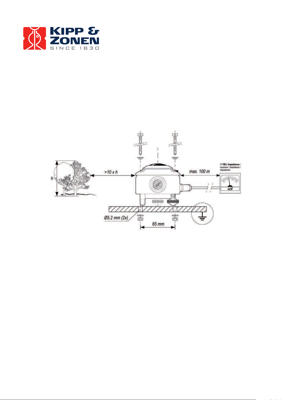
3. Mounting
The CGR pyrgeometer is provided with two holes for 5 mm bolts. Two each of stainless steel bolts,
washers, nuts and nylon insulation rings are provided in the fixing kit. The pyrgeometer should first be
secured lightly with the bolts to a solid and stable mounting stand or platform as shown in Figure 1. After
recalibration the nylon insulators must be replaced with new ones to prevent corrosion.
The mounting stand temperature can vary over a wider range than the air temperature. Temperature
fluctuations of the pyrgeometer body can produce offset signals, therefore it is recommended to isolate
the pyrgeometer thermally from the mounting stand by placing it on its levelling screws. Ensure that
there is a good electrical contact with earth to conduct away currents in the cable shield induced by
lightning.
Figure 1: Pyrgeometer installation
Note: After recalibration and/or reinstallation the nylon insulators must be replaced with new ones to maintain durability.
4. Orientation
In principle no special orientation of the instrument is required, although the World Meteorological
Organisation (WMO) recommends that the signal lead is pointed towards the nearest pole, to minimise
heating of the electrical connections.
5. Level pyrgeometer
Accurate measurement of the global radiation requires proper levelling of the thermopile surface. Level
the instrument by turning the two levelling screws to bring the bubble of the spirit level centrally within
the marked ring. For easy levelling, first use the screw nearest to the spirit level. When the pyrgeometer
is placed horizontally using the bubble level, or when it is mounted with its base directly on a horizontal
plane, the thermopile is horizontal within 0.1°.
Page 7CGR 4 Manual
Page 8
6. Secure pyrgeometer
Secure the pyrgeometer tightly with the two stainless steel bolts. Ensure that the pyrgeometer maintains
the correct levelled position!
7. Fit cable and sun shield
Locate the cable plug correctly in the radiometer socket (it only fits one way) and screw the plug locking
ring hand-tight. Finally, clip on the sun shield to prevent excessive heating of the radiometer body.
The bubble level is visible through the top of the sun shield for routine checks.
2.2.2. Installation for measurement of radiation on inclined surfaces
It is advised to pre-adjust the levelling screws on a horizontal surface for easy orientation of the
instrument parallel to the inclined surface. Because the temperature of the mounting stand is expected
to rise considerably (more than 10°C above air temperature), the housing must be thermally isolated
by the levelling screws from the stand. This will promote a thermal equilibrium between the dome and
the housing and decrease zero offset signals.
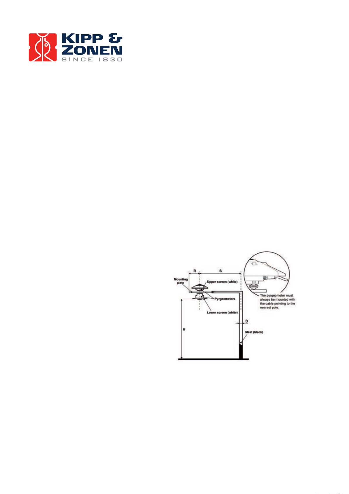
2.2.3. Installation for measurement of upward long-wave radiation
In the inverted position the pyrgeometer measures radiation from the ground. According to the WMO the
height should be 1 m to 2 m above a uniform surface covered by short grass.
The mounting device should not interfere
significantly with the field of view of the
instrument. The upper plate prevents excessive
heating of the pyrgeometer body by solar
radiation and, if large enough, it keeps the
lower screen free of precipitation. The lower
glare screen prevents direct illumination of the
dome by the sun at sunrise and sunset and is
available as an accessory kit for the CGR series.
The mast shown in Figure 2 intercepts a
fraction D/2πS of the radiation coming from
the ground. In the most unfavourable
situation (sun at zenith) the pyrgeometer
shadow decreases the signal by a factor R²/H².
A rule of thumb is:
A black shadow with radius = 0.1 H on the field
below decreases the signal by 1% and 99% of
the signal will originate from an area with
radius 10 H.
Figure 2: Upward long-wave radiation
Page 8 CGR 4 Manual
Page 9
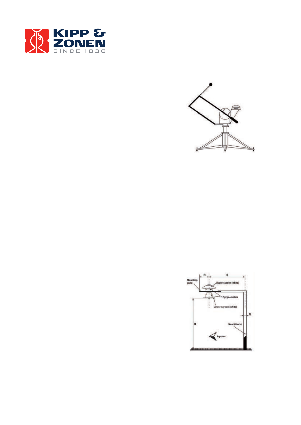
2.2.4. Installation for shaded measurement of downward long-wave radiation
For measuring atmospheric radiation with some pyrgeometers,
such as the CGR 3, it is desirable to shield the instrument from
the direct short-wave solar radiation which may heat up the
pyrgeometer dome or window and cause significant thermal
offsets. The direct solar radiation is intercepted by a small disk or
sphere. The shadow of the disk must cover the pyrgeometer dome
completely. However, to follow the sun's apparent motion, a
power-driven tracking device is necessary.
This can be done using a Kipp & Zonen sun tracker, such as the
model 2AP, designed to track the sun accurately under all
weather conditions. More information about the combination of
pyrgeometer and tracker is given in the sun tracker manual.
Alternatively, a static shadow ring can be used to intercept the direct solar radiation; but it is less
accurate and may require periodic manual adjustment. At times the shadow ring also intercepts a
proportion of the diffuse sky radiation. Therefore, corrections for this to the recorded data are necessary.
Kipp & Zonen produces a universal shadow ring, model CM 121, which is suitable for use at all latitudes.
In the CM 121 manual, installation instructions and correction factors are given.
In practice the CGR 4 does not require shading from direct short-wave solar radiation because the
dome-heating effect, when suitably ventilated, is negligible due to the unique construction of the
pyrgeometer.
Figure 3: 2AP Sun Tracker with
shaded pyrgeometer
2.2.5. Installation for measurement of net long-wave radiation
A net pyrgeometer measures both the downward atmospheric long-wave radiation and the upward
long-wave radiation from the surface below. It can be configured from two CGR series pyrgeometers and
a suitable mounting plate. In the case of the CGR 3, two instruments can be simply mounted back-to-back
and an optional mounting rod fitted.
The requirements for installation of the upper and lower
pyrgeometers are the same as in paragraphs 2.2.1 and 2.2.3 for
downward and upward long-wave radiation.
A typical arrangement is shown in Figure 4. According to the
WMO the height should be 1 m to 2 m above a uniform surface
covered by short grass.
The mast shown intercepts a fraction D/2πS of the radiation that
is coming from the ground. In the most unfavourable situation
(sun at zenith) the pyrgeometer shadow decreases the signal by a
factor R²/H².
When determining the net long-wave radiation, it is not strictly
necessary to record the pyrgeometer housing temperatures.
Assuming that the temperatures of the upper and lower housings
are equal, it can be cancelled from the equation for net-radiation.
Figure 4: Net radiation configuration
CGR 4 Manual
Page 9
Page 10

However, if the upward and downward radiation components are to be measured separately it is necessary
to record the individual housing temperatures to calculate the radiation values.
Using the combination of a net pyrgeometer (two CGR 3 or CGR 4 instruments) and a CMA 6 or CMA 11
albedometer the net total radiation (energy balance) can be calculated with high accuracy from thefour
component values. Problems with dew deposition, frost, etc, can be minimised by using the Kipp &
Zonen CV 2 ventilation unit with optional heating.
This has many advantages over conventional net total radiation sensors with plastic (polyethylene)
windows. These cannot provide individual short and long-wave radiation values and cannot separate
upward and downward contributions. The soft plastic domes do not fully protect the sensor from the
thermal effects of wind and rain, are easily soiled, are difficult to clean and require regular replacement.
2.3. Electrical installation
As standard the CGR is supplied with a waterproof connector pre-wired to 10 m cable with a number of
leads and a shield covered with a black sleeve. The number of connector pins and cable leads depends
upon the type of temperature sensor that is fitted. The colour code of the wires and the connector pin
numbers are shown on the instruction sheet. Longer cables are available as options.
Preferably, secure the pyrgeometer with its levelling screws or mounting rod to a metal support with a
good connection to earth (e.g. by using a lightning conductor).
The shield of the cable is connected to the aluminium radiometer housing through the connector body.
The shield at the cable end may be connected to ground at the readout equipment. Lightning can induce
high voltages in the shield but these will be led off at the pyrgeometer and data logger.
Kipp & Zonen pyrgeometer cables are of low noise type, but bending the cable produces small voltage
spikes, a tribo-electric and capacitance effect. Therefore, the cable must be firmly secured to minimise
spurious responses during stormy weather.
The impedance of the readout equipment loads the temperature compensation circuit and the thermopile.
It can increase the temperature dependency of the pyrgeometer. The sensitivity is affected more than 0.1%
when the load resistance is less than 100 kΩ. For this reason we recommend the use of readout equipment
with an input impedance of 1 MΩ or more. The solar integrators, data loggers and chart recorders from
Kipp & Zonen meet these requirements.
Long cables may be used, but the cable resistance must be smaller than 0.1% of the impedance of the
readout equipment. It is evident that the use of attenuator circuits to modify the calibration factor is not
recommended because the temperature response will also be affected.
A high input bias current at the readout equipment can produce several micro-Volts across the impedance
of the pyrgeometer and cable. The zero offset can be verified by replacing the pyrgeometer impedance at
the readout equipment input terminals with a resistor.
The pyrgeometer can also be connected to a computer or data acquisition system. A low voltage analogue
input must be available. The resolution of the Analogue-to-Digital Converter (ADC) must allow a system
sensitivity of about 1 bit per W/m². More resolution is not necessary during outdoor measurements,
because even the best pyrgeometer (the CGR 4) exhibits offsets greater than 2 W/m² due to lack of
thermal equilibrium.
Page 10 CGR 4 Manual
Page 11

2.2.4. Installation for shaded measurement of downward long-wave radiation
For amplification of the pyrgeometer signal Kipp & Zonen offers the AMPBOX signal amplifier.
This amplifier will convert the micro-Volt output from the pyrgeometer into a standard 4 – 20 mA signal.
The use of the AMPBOX amplifier is recommended for applications with long cables (> 100m), electrically
noisy environments or data loggers with a current-loop input.
The AMPBOX can be factory adjusted to suit the sensitivity of an individual pyrgeometer to produce a
defined range, typically 4 mA represents -300 W/m², 16 mA represents 0 W/m2 and 20 mA represents
+100 W/m².
2.4. Operation
After completing the installation the pyrgeometer will be ready for operation. The downward atmospheric
long-wave radiation can be calculated with Formula 1 by measuring the detector output voltage Uemf [µV],
the housing temperature T
[K], and taking the sensitivity calibration factor S [µV/W/m²] into account.
b
U
emf
Formula 1
Ld=
=Downward atmospheric long-wave radiation [W/m²]
L
d
=Net radiation (difference between the downward [W/m²]
U
emf
longwave radiation emitted from the atmosphere
S
and the upward irradiance of the CGR 4 detector)
=Upward irradiance of the CGR 4 detector [W/m²]
5.67 • 10
Note that the net radiation term (U
long-wave radiation is smaller than the detector’s upward irradiance ( ).
This refers to the net radiation within the pyrgeometer, not the ‘net radiation’ as referred to in 2.2.5.
In the Baseline Surface Radiation Network (BSRN) manual (WMO/TD-No.897) an extended formula is
described. This formula corrects for window heating and so called “solar radiation leakage”. Due to the
very low window heating offset and optimal spectral cut-on wavelength, these corrections are not
necessary for the CGR 4.
To be certain that the quality of the data is of a high standard, care must be taken with daily maintenance
of the pyrgeometer. Once a voltage measurement is taken, nothing can be done to retrospectively
improve the quality of that measurement.
S
+
5.67 • 10
4
-8
• T
b
4
-8
• T
b
/ S) is mostly negative, so the calculated downward atmospheric
emf
5.67 • 10
4
-8
• T
b
During field measurements the pyrgeometer is exposed to varying atmospheric conditions with typical
radiating properties. Therefore we define the two most common conditions as ‘overcast sky’ and ‘clear
sky’, refer to 2.4.1 and 2.4.2 respectively.
CGR 4 Manual
Page 11
Page 12

2.4.1. Overcast sky
Typical for a cloudy overcast sky is that radiation emitted by the earth is absorbed 100% by the clouds.
Therefore, the overcast sky will re-emit the radiation (L
) 100%.
d
In theory, the net radiation (U
/ S) will be zero, so the pyrgeometer detector output voltage (U
emf
emf
)
will be zero. In practice, the detector output shows a small negative voltage (a few W/m²), due to a
small heat exchange between the relatively warm pyrgeometer and the colder sky.
In this case the calculated atmospheric long-wave radiation (L
) shows a relatively large positive value.
d
In the case of rain, the detector output will read zero, because water deposited on the pyrgeometer
window is a perfect infrared absorber. A cloudy overcast sky condition is illustrated in Figure 5.
Figure 5: Cloudy overcast sky condition
2.4.2. Clear sky
Clear sky conditions differ in that there is a relatively large heat loss caused by the atmospheric window.
The amount of re-emitted radiation by a clear sky is smaller compared to the overcast sky condition.
Because of the heat loss in the upward direction, the thermopile hot junctions will cool down and show a
relatively large negative net radiation value (from -90 to -130 W/m²). Therefore, the calculated atmospheric
long-wave radiation (L
) shows a relative small positive value. A clear sky condition is illustrated in Figure 6.
d
Figure 6: Clear sky condition
Page 12 CGR 4 Manual
Page 13

2.4.3. Measurements during a sunny day
The CGR 4 differs from all other pyrgeometers in that it allows accurate daytime measurements on
sunny days without the need for a shading device. Due to the unique construction of the CGR 4, solar
radiation of up to 1000 W/m² induces window heating of less than 4 W/m² in the overall calculated
downward radiation.
Formula 1 can be applied without any problems with the following exception; one must take note of the
amount of Infrared radiation in the solar spectrum. The amount of solar infrared radiation depends on
many parameters; for example the water vapour content in the atmosphere (humidity), location of the
CGR 4 at a certain altitude and the sun’s declination angle. Figure 7 indicates the possible infrared
radiation in the solar spectrum in the case of low water content in the atmosphere. The amount of solar
infrared detected at the CGR 4 (and the CGR 3) is expected to be very low (0 to 3 W/m²) because of the
filter cut-on at 4.5 µm. Other types of pyrgeometers can exhibit 0 – 10 W/m².
Figure 7: Direct solar irradiance in Davos, Switzerland at solar noon in mid-September
2.5. Measurement uncertainty
When a pyrgeometer is in operation, the performance of it is correlated to a number of parameters, such
as temperature, level of irradiance, angle of incidence, etc. Normally, the supplied sensitivity figure is
used to calculate the irradiances. If the conditions differ significantly from calibration conditions,
uncertainty in the calculated irradiances must be expected.
Kipp & Zonen expects maximum uncertainty below 3% for daily totals for the CGR 4 pyrgeometer. This
remaining uncertainty can be reduced further if the sensitivity of the pyrgeometer under the prevailing
conditions is used, with corrections calculated from the effects of parameters such as temperature and
non-linearity. This is especially convenient with a programmable data acquisition system.
Page 13CGR 4 Manual
Page 14

For the CGR 4 the effect of each parameter on the sensitivity can be shown separately. The non-linearity
error, the sensitivity variation with irradiance, is the same for any CGR 4 and is shown in Figure 8.
Figure 8: Non-linear sensitivity variation with irradiance of a CGR 4 pyrgeometer
The temperature dependence of the sensitivity is a function of the individual CGR 4. For a given CGR 4 the
response lies in the region between the curved lines in Figure 9. The temperature dependence of each CGR
4 pyrgeometer is characterised and supplied with the instrument. Each CGR 4 has a built-in temperature
sensor to allow corrections to be applied if required.
Figure 9: Typical temperature dependency of a CGR 4
Page 14 CGR 4 Manual
Page 15

2.6. Maintenance
Once installed the pyrgeometer needs little maintenance. The dome/window must be cleaned and
inspected regularly, ideally every morning. On clear windless nights the dome/window temperature of
horizontally placed pyrgeometers will decrease, even to the dew point temperature of the air, due to
infrared radiation exchange with the cold sky. (The effective sky temperature can be 30°C lower than
the ground temperature). In this case dew, glazed frost or hoar frost can be precipitated on the top of
the outer dome and can stay there for several hours in the morning. An ice cap on the dome is a strong
diffuser and increases the pyrgeometer signal drastically, up to 100% in the first hours after sunrise.
Hoar frost disappears due to solar radiation during the morning, but should be wiped of as soon as
possible manually.
The dome of the pyrgeometer can be ventilated continuously by a heated blower to keep the
dome/window above the dew point temperature. The need for heating strongly depends upon local
climatological circumstances. Generally, heating is advised during cold seasons when frost and dew
can be expected. The Kipp & Zonen CV 2 ventilation unit is specially designed for unattended operation
under most weather conditions and has a choice of heating levels.
Note that the CGR 3 pyrgeometer cannot be used with the CV 2 ventilation unit.
A periodic check is to ensure that the pyrgeometer is level and that the silica gel desiccant is still
coloured orange. When the orange silica gel in the drying cartridge is turned completely transparent
(normally after several months), it must be replaced by fresh silica gel as supplied in the small refill
packs. The content of one pack is sufficient for one complete refill. At the same time check that the
pyrgeometer mounting is secure and that the cable is in good condition.
Some tips when changing the desiccant:
- Make sure the surfaces of the pyrgeometer and the drying cartridge that touch the rubber o-ring
are clean (corrosion can do a lot of harm here and dirt, in combination with water, can cause this);
- The rubber o-ring is coated with a silicon grease to improve the seal. If the rubber o-ring looks dry
apply some grease to it (Vaseline will also do);
- Check that the drying cartridge is tightly threaded into the pyrgeometer body.
It is very difficult to make the pyrgeometers hermetically sealed; so, due to pressure differences between
the inside and the outside of the instrument, there will always be some exchange of (humid) air.
The pyrgeometer sensitivity changes with time and with exposure to radiation. Calibration every two years
is advised. Further information about Kipp & Zonen recalibration services can be found in Appendix V.
Page 15CGR 4 Manual
Page 16

3. Principle components of pyrgeometers
The detector of the Kipp & Zonen CGR series pyrgeometer is based on a passive thermal sensing element
called a thermopile. Although the detector construction differs from model to model, the fundamental
working principle is applicable to all CGR series radiometers.
The thermopile responds to the total power absorbed by the black surface coating, which is a nonspectrally
selective paint, and warm up. The heat generated flows through a thermal resistance to the heat-sink
(the pyrgeometer body). The temperature difference across the thermal resistance of the detector is
converted into a voltage as a linear function of the absorbed solar irradiance.
The rise of temperature is easily affected by wind, rain and thermal radiation losses to the environment
('cold' sky). Therefore the CGR 4 detector is shielded by a silicon meniscus dome (the entry-level CGR 3
has a flat silicon window to reduce cost). A drying cartridge (desiccator) in the radiometer housing is
filled with silica gel and prevents dew on the inner sides of the domes, which can cool down considerably
on clear windless nights.
Figure 10: Construction details of CGR 4 pyrgeometer
3.1. Window
The inner surface of the silicon dome / window has an interference filter deposited on it for transmitting
the long-wave radiation and blocking the short-wave solar radiation from reaching the detector. The
silicon window material and the deposited ‘solar blind’ filter defines the spectral measurement range
of the pyrgeometer.
The silicon window allows transmittance of the atmospheric long-wave radiation up to approximately
42 µm and about 50 - 60% of the radiation spectrum will be transmitted through to the detector. The
outer surface of the CGR 4 dome has a hard-carbon, diamond-like layer, deposited as additional
protection against environmental influences in harsh environments and to smooth out the window
transmission beyond 30 µm.
Page 16
CGR 4 Manual
Page 17

The solar blind filter is opaque to radiation below 4.5 µm, known as the cut-on wavelength. Currently
most pyrgeometers have their cut-on at a lower wavelength. Problems may occur in the case of clear
sunny days with low humidity. In the solar spectrum between 2.5 and 4.5 µm there can still be an
amount of infrared solar radiation up to 10 W/m², which should not be included in the measurement.
This unwanted fraction is blocked in the CGR 4 by the filter coating.
CGR 4 uses a specially designed pure silicon dome. Although the dome is not hemispherical, CGR 4 has
a 180° field of view with good cosine response. A big advantage of the meniscus shaped dome over the
typical hemispherical dome is the ability to deposit more uniform coatings on the window surface.
Deposition of a uniform filter coating on a strongly curved surface is very difficult and unpredictable
process. To avoid these problems Kipp & Zonen developed a dome with excellent optical quality due to
the optimised shape and coating uniformity.
The solar radiation absorbed by the window is conducted away very effectively by a unique construction
in the CGR 4. Even in full sunlight the window heating effect is very low compared to that of other
pyrgeometers on the market. This allows accurate daytime measurements without the need for a
shading disk. It also eliminates the need for window heating compensation by using the correction
formula and window temperature sensors.
3.2. Detector
The thermopile sensing element is made up of a large number of thermocouple junction pairs
connected electrically in series. The absorption of thermal radiation by one of the thermocouple
junctions, called the active (or ‘hot’) junction, increases its temperature. The differential temperature
between the active junction and a reference (‘cold’) junction kept at a fixed temperature produces an
electromotive force directly proportional to the differential temperature created. This is a thermoelectric
effect. The sensitivity of a pyrgeometer depends on the individual physical properties of the thermopile
and construction. The sensitivity of each thermopile is unique and therefore each radiometer has
unique calibration factor, even with the same radiometer model.
On the top surface of the sensor a black paint is deposited which has a very rough structure containing
many micro-cavities that effectively ‘trap’ more than 95% of the incident radiation in a broad spectral
range. Furthermore, the spectral selectivity is less than 3%. This means that within the spectral range
of the pyrgeometer, the absorption for each wavelength is equal to within 3%. The black painted
sensing element forms the detector. Considering the long-term stability of the instrument, the black
paint is one of the most crucial and delicate parts of the pyrgeometer. Kipp & Zonen black paint gives
the best possible stability over a long period of time under all meteorological circumstances.
3.3. Temperature sensor
The housing temperature sensor is a crucial part of a pyrgeometer and is needed to calculate the
downward long-wave radiation component. The body temperature sensor represents the ‘absolute’
temperature of the detector surface and therefore it is mounted close to the cold junctions of the
detector. A housing temperature sensor is fitted as standard to the CGR pyrgeometers.
Page 17CGR 4 Manual
Page 18

3.4. Housing
The radiometer housing accommodates all fundamental pygeometer parts. The anodized Aluminium
parts are light weight and give a high mechanical and thermal stability to the instrument. Due to its fine
mechanical construction all pyrgeometers are virtually sealed and comply to the international standard
IP 67. Each pyrgeometer model can be leveled by using the bubble level and two leveling feet. For ease
of maintenance the bubble level is situated next to the dome of the instrument and due to the special
shape of the sun shield it is visible from above. The sun shield acts to protects all the external parts from
radiation and to reduce solar heating of the housing.
3.5. Drying cartridge
In case moisture enters the radiometer body the silica-gel desiccant regulates the humidity level inside
the pyrgeometer. Initially the desiccant will have an orange colour. After some time it becomes saturated
with moisture and the colour will change to become clear (transparent). At this time the contents of the
drying cartridge should be replaced with fresh, unsaturated orange colored desiccant as soon as possible.
Replacement desiccant is available through Kipp & Zonen distributors.
3.6. Cable and connector
For ease of installation and replacement during recalibration of the radiometer, the CGR series are
provided with a weather proof signal cable connector.
Kipp & Zonen radiometers use a custom-made cable that is selected as a low noise type particularly
suited to handle the low voltage output of the thermopile or of a temperature sensor.
The shield of the cable is connected to the metal body of the connector and preferably should be
connected to ground at the readout equipment. Cables come pre-wired to the connector plug in a range
of lengths.
Page 18 CGR 4 Manual
Page 19

4. Pyrgeometer physical properties
4.1. Spectral range
The spectral properties of the pyrgeometer are mainly determined by the filter characteristics of the silicon
window and the coatings. The application is primarily to measure long-wave downward atmospheric
radiation. The spectral range is from 4.5 to 42 µm, where most of this radiation is present.
Figure 11: Pyrgeometer spectral window properties
The atmosphere is transparent to long-wave radiation emitted by the Earth’s surface in certain wavelength
intervals, particularly within a spectral range of approximately 8 to 14 µm. This is called the ‘atmospheric
window’. Within this spectral range the Earth is able to maintain an equilibrium temperature by losing a
certain quantity of heat gained each day from the sun.
The sun radiates approximately as a blackbody at an equivalent temperature of 5770K. Almost 99% of its
emitted energy is contained in wavelengths less than 4µm, called short-wave radiation. The equivalent
radiant temperature of the Earth’s surface is about 275K. More than 99% of this energy is emitted at
wavelengths greater than 3 µm and is called long-wave, thermal, or infrared radiation.
Downward long-wave radiation is a result of atmospheric
re-emission. Re-emission is the reversible effect of
absorption of long-wave radiation emitted by the Earth
and by chemical elements such as water (H₂O), Oxygen
(O₂), Ozone (O₃), Carbon dioxide (CO₂), etc. These
elements are the main emitters of long-wave radiation in
the atmosphere. The remaining unabsorbed portion of the
Earth’s radiation escapes into outer space. Under clear skies
an object can be cooled below ambient air temperature by
radiative heat loss to the sky.
Observing the earth from outer space, a blackbody is seen
in a range of 8 to 14 µm with a temperature of 14°C and
outside this wavelength range a blackbody of -60°C.
Under clear sky conditions in a reverse direction, outer Figure 12: Atmospheric radiation
space can be observed in the same spectral range.
Page 19CGR 4 Manual
Page 20

4.2. Sensitivity
The radiometer thermopile sensitivity is mainly determined by the physical properties of the detector
itself. The thermoelectric power, thermal conductivity of the junctions and the overall dimensions of the
sensing element are related to its sensitivity.
4.3. Impedance
The radiometer impedance is defined as the total electrical impedance at the radiometer output connector
fitted to the housing. It arises from the electrical resistance in the thermal junctions, wires and passive
electronics within the radiometer.
4.4. Response time
Any measuring device requires a certain time to react to a change in the parameter being measured. The
radiometer requires time to respond to change in the incident radiation. The response time is normally
quoted as the time for the output to reach 95% (sometimes 63%) of the final value following a step-change
in irradiance. It is determined by the physical properties of the thermopile and the radiometer construction.
CGR series pyrgeometers have a fast response, which makes them suitable for measuring far infrared
radiation (FIR) under variable weather conditions.
4.5. Non-linearity
The non-linearity of a pyrgeometer is the percentage deviation in the sensitivity over a net irradiance
range from -250 to +250 W/m² compared to the sensitivity calibration irradiance of -100 W/m². The
non-linearity effect is due to convective and radiative heat losses at the black absorber surface which
make the conditional thermal equilibrium of the radiometer non-linear.
4.6. Temperature dependence
The sensitivity change of the pyrgeometer with ambient temperature change is related to the thermodynamics
of the radiometer construction. The temperature dependence is given as percent deviation with respect to
the calibrated sensitivity at +20°C. The CGR 4 has passive electrical compensation circuits to minimise
this effect. Each CGR 4 pyrgeometer is supplied with an individual test certificate stating the temperature
dependency in the range from -20°C to +50°C, at 10°C intervals. The CGR series pyrgeometers are fitted
as standard with an internal temperature sensor to allow sensitivity corrections to be applied if desired.
4.7. Tilt error
This is the deviation from the sensitivity at 0° tilt (exactly horizontal) over the range from 0° to 90° tilt.
The tilt response is proportional to the incident radiation. The error could be corrected for, in applications
where it is necessary to install the pyrgeometer on an inclined surface, but is usually insignificant.
Page 20 CGR 4 Manual
Page 21

4.8. Window heating offset
Currently the major source of error concerning common pyrgeometer measurements is caused by the
so-called ‘window heating offset’. When a pyrgeometer is exposed to the sun, heating of the silicon
dome/window occurs due to absorption of solar radiation by the material. As a consequence the
dome/window of most types of pyrgeometer will heat up proportionally to the solar irradiance.
The resulting temperature difference between dome/window and thermopile will cause heat transfer by
radiation and convection to the sensor. This affects the net thermal radiation as measured by the thermopile
and is commonly referred to as the ‘window heating offset’. The result is measurement of a too high value
for downward long-wave radiation.
This offset is not easily reduced by ventilation, which only cools off 50 W/m²/°C at maximum while
solar radiation can be absorbed at a rate of about 500 W/m² on a sunny day. Currently certain types of
pyrgeometers are equipped with one or more thermistors to measure the dome/window absolute
temperature that represents the apparent offset. A complex calculation must be performed to eliminate
the offset.
Arguments against a thermistor to measure window temperature are:
- The thermistor contacts a part of the dome/window, it is a blackbody radiator and heat source itself
and its material and adhesive increases the mean emission coefficient of the inner dome/window
surface. Its presence increases the window-heating offset.
- Under clear skies the direct solar irradiance impacts mainly from one direction, so for a
hemispherical dome it is recommended to have 3 equally-spaced thermistors to determine the
mean dome temperature.
- The dome/window thermistor(s) should be carefully matched with the housing thermistor because
calculations must be done using the temperature difference of the two thermistors.
- The customer needs between one and three extra data logger channels for the dome/window
thermistor inputs.
Because of the possible problems caused by dome / window thermistors Kipp & Zonen developed the
revolutionary CGR 4 pyrgeometer. In the CGR 4, dome heating is strongly suppressed by a unique
construction that very effectively conducts the absorbed heat away into the housing. CGR 4 temperature
variations between dome and detector are less than 0.3°C, compared with up to 3°C for other types of
pyrgeometers. In CGR 4 the window heating offset is less than 4 W/m². This allows accurate daytime
measurements, even in full sunlight, without the need for a tracking shading disk.
4.9. Zero offset B due to ambient temperature changes
Proportionally to the ambient temperature the instrument temperature varies and causes heat currents
inside the instrument. This will cause an offset commonly called Zero Offset type B. It is quantified as the
response in W/m² to a 5 K/hr change in ambient temperature.
Page 21CGR 4 Manual
Page 22

4.10. Operating temperature
The operating temperature range of the radiometer is determined by the physical properties of the
individual parts. Within the specified temperature range Kipp & Zonen radiometers can be operated
safely. Outside this temperature range special precautions should be taken to prevent any physical
damage or performance loss of the radiometer. Please contact your distributor for further information
regarding operation in unusually harsh temperature conditions.
4.11. Field of view
The field of view is defined as the unobstructed open viewing angle of the radiometer. WMO requires
that a high quality pyrgeometer for the measurement of long-wave atmospheric radiation has a field of
view of 180° in all directions (i.e. a hemisphere). CGR 4 achieves this. The inherent field of view of the
instrument should not be confused with the clear field of view of the installation location.
For less critical applications pyrgeometers having a flat silicon window with a typical field of view of
150° are acceptable, such as the CGR 3.
4.12. Directional response
Radiation incident on a flat horizontal surface originating from a point source with a defined zenith
position will have an intensity value proportional to the cosine of the zenith angle of incidence. This is
sometimes called the ‘cosine-law’ or ‘cosine-response’ and is very important in the measurement of
short-wave solar radiation. However, the directional response of pyrgeometers is largely irrelevant
since the hemisphere above does not act like a point source.
4.13. Maximum irradiance
The maximum irradiance is defined as the total irradiance level beyond which physical damage may
occur to the instrument.
4.14. Non-stability
This is the percentage change in sensitivity over a period of one year. This effect is mostly due to
degradation by UV radiation of the black absorber paint on the sensing element surface. Kipp & Zonen
recommends recalibration every two years. However, for quality assurance purposes some institutes,
companies or networks may require more or less frequent recalibration. Please read the chapter on
the calibration procedure for pyrgeometers for more information.
4.15. Spectral selectivity
Spectral selectivity is the variation of the dome transmittance and absorption coefficient of the black
detector paint with wavelength and is commonly specified as % of the mean value.
Page 22 CGR 4 Manual
Page 23

4.16. Environmental
The CGR series are intended for outdoor use under all expected weather conditions. The radiometers
comply with IP 67 and their solid mechanical construction is suitable to be used under all environmental
conditions within the specified ranges.
4.17. Uncertainty
The measurement uncertainty can be described as the maximum expected hourly or daily uncertainty
with respect to the ‘absolute truth’. The confidence level is 95%, which means that 95% of the
datapoints lie within the given uncertainty interval representing the absolute value. Kipp & Zonen
empirically determine uncertainty figures based on many years of field measurements.
CGR 4 Manual
Page 23
Page 24

5. Calibration
5.1. Calibration principle
An ideal radiometer gives voltage output that is proportional to the absolute irradiance level. This
relationship can be expressed as a constant ratio called ‘sensitivity’ (Sensitivity).
The sensitivity figure of a particular pyrgeometer is unique. In the case of the CGR 4 it is determined
outdoors by comparison against a reference CGR 4 pyrgeometer. The reference pyrgeometer is
calibrated outdoors regularly at the World Radiation Centre (WRC) at Davos, Switzerland.
5.2. Calibration procedure at Kipp & Zonen
CGR 4 pyrgeometers are calibrated outdoors at Kipp & Zonen under a mainly clear sky during nighttime.
The test instruments are installed next to the reference CGR 4. The pyrgeometer detector outputs (U
and housing temperatures (T
Afterwards the downward radiation (L
) are measured each second and compressed to one minute averages.
b
) on the reference pyrgeometer is calculated using Formula 2.
d
emf
)
U
emf
+
Ld=
Formula 2
For the test CGR 4’s a one minute average sensitivity is calculated using the Formula 3.
Formula 3
St=
(L
A final S
Net IR-exchange > 40 W/m².
The sum of all periods must be at least 6 hours for a successful calibration.
5.67 • 10
S
U
t
- )
5.67 • 10
d
is determined using only one minute St’s determined under clear sky conditions when;
t
-8
(L
d b
4
-8
• T
b
4
• T
b
4
-8
- )
5.67 • 10
• T
5.3. Traceability to World Radiometric Reference
Reference radiometers, which are calibrated annually by the World Radiation Centre in Davos, are used
for the calibration of radiometers manufactured by Kipp & Zonen. The reference radiometers are fully
characterized, i.e. linearity, temperature dependence and directional response are recorded.
Kipp & Zonen keeps two reference radiometers for each radiometer model. These reference radiometers
are sent alternate years to WRC for calibration, so production and calibration in Delft can carry on
without interruption.
5.4. Recalibration
Radiometer sensitivity changes with time and with exposure to radiation. Periodic calibration every two
years is advised. Accurate calibrations can be done outdoors under clear sky conditions by comparison
to a reference pyrgeometer of equal or higher standard.
Page 24 CGR 4 Manual
Page 25

6. CGR models
The CGR series comprises 2 models, CGR 3 and CGR 4. The mechanical construction of the CGR 3 differs
from the CGR 4 in that it has a flat silicon window, smaller housing dimensions and no drying cartridge
(the housing is completely sealed). Features and specifications of the CGR 4 pyrgeometers are given in
this chapter. The CGR series is designed for measuring the downward radiation (W/m²) on a plane
surface from the atmosphere above.
CGR 4 pyrgeometer includes an integrated bubble level, refillable drying cartridge, white snap-on sun
shield, and a shielded signal output cable with connector.
CGR 4 can be used in conjunction with the Kipp & Zonen CV 2 ventilation unit for enhanced measurement
performance and overall reduced instrument maintenance.
For reducing the window heating offset error, the direct solar radiation can be shielded statically from
the CGR 3 pyrgeometer by the Kipp & Zonen shadow ring CM 121, and fully automatically by the 2 AP Sun
Tracker with shading system. This can also be done for the CGR 4 but is not really necessary because of
the minimal window heating effect.
A net pyrgeometer measures both the downward atmospheric long-wave radiation and the upward
long-wave radiation from the surface below. It can be configured from two CGR 4 series pyrgeometers
and a suitable mounting plate. In the case of the CGR 3, two instruments can be simply mounted
back-to-back and an optional mounting rod fitted.
6.1. CGR 4
CGR 4 has been designed for scientific measurements outdoors of downward atmospheric long-wave
radiation with extremely high reliability and accuracy.
CGR 4 provides an output voltage that is proportional to the net radiation in the far infrared (FIR). By
calculation, downward atmospheric long-wave radiation is derived. CGR 4 has an integrated temperature
sensor to measure the housing temperature.
CGR 4 uses a specially designed silicon meniscus dome. Although the window is not hemispherical, CGR 4
has a 180° field of view with good cosine response. A hard-carbon, diamond-like, coating protects the
outer surface of the window and smoothes the spectral response. On the inside, a solar blind interference
filter blocks all short-wave solar radiation.
The solar radiation absorbed by the window is conducted away into the housing very effectively, by a
unique construction. Even in full sunlight the window heating offset is very low compared to that of other
pyrgeometers on the market. This allows accurate daytime measurements without the need for a tracking
shading disk. It also eliminates the need for window heating compensation by using the correction
formula.
The special features of the CGR 4 are:
- Sensitive to infrared radiation in a wavelength range from 4.5 to 42 µm.
- Extremely low window heating offset.
- 180° field of view with good cosine response.
- Diamond-like coating for optimal protection against environmental influences.
- Low temperature dependence of sensitivity.
Page 25CGR 4 Manual
Page 26

6.2. CGR 4 performance specifications
Page 26 CGR 4 Manual
Page 27

6.3. CGR 4 general specifications
CGR 4 Manual Page 27
Page 28

7. Frequently asked questions
The most frequently asked questions are listed below. For an update refer to the Kipp & Zonen website at
www.kippzonen.com
- What are typical values for downward atmospheric long wave radiation?
- The values calculated with the formula given in chapter 2 show a very strange value. What could be
the reason?
- Check whether the (instrument) temperature (T
- Check that the net radiation (U
interchanged.
- Is the pyrgeometer sensitivity affected by the length of the signal cable?
- With longer cable lengths the impedance increases, however it does not affect the radiometer
sensitivity for the following reason. The impedance of the voltage measurement device is at east
10000 times more than the impedance of the pyrgeometer plus cable. Therefore the current that
goes through the readout cable is negligible and won’t generate an offset.However, the loading
may affect the temperature compensation circuit to some extent.
- What is the primary entry point for humidity?
- The drying cartridge seal and the silicon glue of the dome are not fully airtight.
/S) is a negative value, if not, the signal wires are possibly
emf
) is given in Kelvin.
b
Page 28 CGR 4 Manual
Page 29

8. Trouble shooting
The following contains a procedure for checking the instrument in case it appears that it does not
function as it should.
Trouble shooting:
Output signal fails or shows improbable results;
- Check the wires are properly connected to the readout equipment.
- Check the dome, it should be clear and clean. If water is deposited on the inside, please change the
desiccant. If too much water is deposited internally the drying cartridge should be removed and the
instrument warmed to dry it.
- Check instrument impedance (see specifications for expected values).
- Check data logger or integrator offset by connecting a dummy load (100 Ohm resistor). This should
give a ‘zero’ reading.
- Check levelling (bubble inside ring).
If water or ice is deposited on the dome, clean it. Probably water droplets will evaporate in less than one
hour under sunlight.
Any visible damage or malfunction should be reported to your distributor, who will suggest appropriate
action.
CGR 4 Manual Page 29
Page 30

Appendix I Radiometric terminology
Term Explanation
Azimuth angle Angle in horizontal direction (0-360°)
Angle of incidence Incident angle from zenith (vertical)
Cosine response Detector response according to the cosine law
Global solar irradiance Total irradiance falling on a horizontal surface (Diffuse+Direct • cos α)
Irradiance Radiant flux density (W/m²)
Long-wave radiation Radiation with wavelengths > 4 µm and < 100 µm
Long-wave downward radiation Radiation emitted by the sky
Net radiation Long-wave downward radiation minus outgoing radiation
Pyrgeometer Radiometer suitable to measure downward long-wave radiation
Short-wave radiation Radiation with wavelengths > 280 nm and < 4 µm
Thermopile Thermal detector made up of many thermocouple junctions
WMO World Meteorological Organisation
WRC World Radiation Center (in Davos, Switzerland)
Zenith angle Angle from zenith (0°, vertical)
Page 30 CGR 4 Manual
Page 31

Appendix II 10kΩ thermistor specifications
YSI Thermistor 44031 - Resistance versus Temperature in °C
Thermistor (10 kΩ @ 25ºC)
(α+[
β•(ln(R))+ γ•(ln(R))
T
=
α : 1.0295 • 10
-3
β : 2.391 • 10
-1
3
])
-4
γ : 1.568 • 10
-273.15
[ºC]
[Ω]
Temperature
=
=
Resistance
T
R
-7
CGR 4 Manual
Page 31
Page 32

Appendix III Pt-100 specifications
Pt-100 - Resistance versus Temperature in ºC and ºF
TemperatureT[ºC
]
=
[Ω]
Resistance
=
R
Pt-100 (100 Ω @ 0ºC)
-α+ α2-4
T
=
α
: 3.9083 • 10
•β•
2
-3
β
-R
+1
100
•
β
: -5.8019 • 10
-7
Page 32
CGR 4 Manual
Page 33

Appendix IV List of World and Regional Radiation Centres
World Radiation Centre
The World Radiation Centre capable of pyrgeometer calibration is located at:
Physikalisch-Meterologisches Observatorium
Dorfstrasse 33
CH-7260
Davos Dorf
Switzerland
Website: www.pmodwrc.ch
CGR series Manual Page 33
Page 34

Appendix V Recalibration service
Pyranometers, Albedometers, Pyrgeometers, UV-Radiometers & Sunshine Duration Sensors
Kipp & Zonen solar radiation measurement instruments comply with the most demanding international
standards. In order to maintain the specified performance of these instruments, Kipp & Zonen recommends
calibration of their instruments every two years.
This can be done at the Kipp & Zonen factory. Here, recalibration to the highest standards can be
performed at low cost. Recalibration can usually be performed within four weeks. If required, urgent
recalibration can be accomplished in three weeks or less (subject to scheduling restrictions).
Kipp & Zonen will confirm the duration of recalibration at all times. Please note that special quantity
recalibration discounts are available for instruments of the same type.
CGR series ManualPage 34
Page 35

Our customer support remains at your disposal for any maintenance or repair, calibration,
supplies and spares.
Für Servicearbeiten und Kalibrierung, Verbrauchsmaterial und Ersatzteile steht Ihnen unsere
Customer Support Abteilung zur Verfügung.
Notre service 'Support Clientèle' reste à votre entière disposition pour tout problème de
maintenance, réparation ou d'étalonnage ainsi que pour les accessoires et pièces de rechange.
Nuestro apoyo del cliente se queda a su disposición para cualquier mantenimiento o la
reparación, la calibración, los suministros y reserva.
HEA D OFFICE
Kipp & Zonen B.V.
Delftechpark 36, 2628 XH Delft
P.O. Box 507, 2600 AM Delft
The Netherlands
T: +31 (0) 15 2755 210
F: +31 (0) 15 2620 351
info@kippzonen.com
SALES OFFICES
Kipp & Zonen France S.A.R.L.
7 Avenue Clément Ader
ZA Ponroy - Bâtiment M
94420 Le Plessis Trévise
France
Kipp & Zonen Asia Pacific Pte. Ltd.
81 Clemenceau Avenue
#04-15/16 UE Square
Singapore 239917
Kipp & Zonen USA Inc.
125 Wilbur Place
Bohemia
NY 11716
United States of America
Go to www.kippzonen.com for your local distributor or contact your local sales office
T: +33
(0) 1 49 62 41 04
F: +33 (0) 1 49 62 41 02
kipp.france@kippzonen.com
T: +65 (0) 6735 5033
F: +65 (0) 6735 8019
kipp.singapore@kippzonen.com
T: +1 (0) 631 589 2065
F: +1 (0) 631 589 2068
kipp.usa@kippzonen.com
Passion for Precision
 Loading...