

Page 1
CFR
Calibration Facility
Instruction Manual
Page 2

1
IMPORTANT USER INFORMATION
Reading this entire manual is recommended for full understanding of
the use of this product.
Should you have any comments on this manual we will be pleased to
receive them at:
Kipp & Zonen B.V.
Delftechpark 36, 2628 XH Delft, The Netherlands
or P.O. Box 507, 2600 AM Delft, The Netherlands
T : +31 (0)15 2755210
F : +31 (0)15 2620351
E : info@kippzonen.com
W : www.kippzonen.com
Kipp & Zonen reserves the right to make changes to the specifications
without prior notice.
WARRANTY AND LIABILITY
Kipp & Zonen guarantees that the product delivered has been
thoroughly tested to ensure that it meets its published specifications.
The warranty included in the conditions of delivery is valid only if the
product has been installed and used according to the instructions
supplied by Kipp & Zonen.
Kipp & Zonen shall in no event be liable for incidental or consequential
damages, including without limitation, lost profits, loss of income, loss of
business opportunities, loss of use and other related exposures,
however used, rising from the faulty and incorrect use of the product.
User made modifications can affect the validity of the CE declaration.
COPYRIGHT© 2006 KIPP & ZONEN
All rights are reserved. No part of this publication may be reproduced,
stored in a retrieval system or transmitted in any form or by any means,
without permission in written form from the company.
Page 3

2
Manual version: 0107
Page 4

3
Declaration of Conformity
According to EC guideline 89/336/EEC
We Kipp & Zonen B.V.
Delftechpark 36
2628 XH Delft
Declare under our sole responsibility that the product
Type: CFR (version 230 VAC / 50Hz)
Name: Calibration Facility for Radiometers
To which this declaration relates is in conformity with the following
standard
Safety standard IEC 1010-1
Following the provisions of the directive.
B.A.H. Dieterink
President
KIPP & ZONEN B.V.
Page 5

CFR manual
4
Table of contents
IMPORTANT USER INFORMATION ............................................................................................................. 1
Declaration of Conformity ............................................................................................................................... 3
Table of contents ............................................................................................................................................ 4
1 Introduction .......................................................................................................................................... 5
2 Installation and operation ..................................................................................................................... 6
2.1 Delivery ................................................................................................................................................ 6
2.2 Installation ............................................................................................................................................ 7
2.2.1 Environmental conditions ................................................................................................................. 7
2.2.2 Mechanical and electrical set-up ...................................................................................................... 7
2.3 Maintenance ...................................................................................................................................... 10
2.3.1 Lamp .............................................................................................................................................. 10
2.3.2 Maintenance and recalibration of the reference pyranometer ........................................................ 10
2.3.3 Spare Parts Specification ............................................................................................................... 12
3 Calibration operation .......................................................................................................................... 13
3.1 Description of the procedure .............................................................................................................. 13
3.2 Description of the procedure step-by-step ......................................................................................... 15
3.3 Calibration uncertainty ....................................................................................................................... 16
3.3.1 Instability of the lamp output power ................................................................................................ 16
3.3.2 Pyranometer offsets ....................................................................................................................... 16
3.3.3 Voltmeter offset .............................................................................................................................. 17
3.3.4 Tilting of the pyranometers ............................................................................................................. 17
3.3.5 Differences in sensor height and geometry .................................................................................... 17
3.3.6 Calibration repeatability and overall uncertainty ............................................................................. 17
3.4 Calibration Form ................................................................................................................................ 18
4 Principle components and specifications of the facility ...................................................................... 19
4.1 Table .................................................................................................................................................. 19
4.2 Turntable ............................................................................................................................................ 19
4.3 Shading mechanism .......................................................................................................................... 20
4.4 Lamp mounting pillar ......................................................................................................................... 20
4.5 Lamp housing .................................................................................................................................... 20
4.5.1 115VAC/60 Hz Calibration Facility ................................................................................................. 20
4.5.2 230VAC/50 Hz Calibration Facility ................................................................................................. 20
4.6 Lamp bulb .......................................................................................................................................... 20
4.7 Voltage Stabilization .......................................................................................................................... 21
4.8 Voltmeter ........................................................................................................................................... 21
4.9 Switch and clamps ............................................................................................................................. 21
4.10 Reference pyranometer .................................................................................................................. 21
4.11 Mountings for other radiometers .................................................................................................... 22
4.12 Stopwatch ...................................................................................................................................... 22
5 Frequently asked questions ............................................................................................................... 23
Appendix I: Calibration Form for pyranometers .......................................................................................... 24
Appendix II: Pyranometer Classification According to WMO Guide 1996 ................................................... 25
Appendix III: List of World and Regional Radiation Centres ......................................................................... 26
Appendix IV:Recalibration service ................................................................................................................ 27
Page 6

CFR manual
5
1 Introduction
Dear customer, thank you for purchasing a Kipp & Zonen product. Please read this manual for a full
understanding of the use of your Calibration Facility.
The CFR Calibration Facility for Radiometers is designed for the calibration of pyranometers by comparison
to a reference pyranometer. As such, it offers a simple and traceable solution for quality control of the
stability of pyranometers used in a network.The procedure described complies with Annex A.3 to the
international standard ISO 9847 "Calibration of Field Pyranometers by Comparison to a Reference
Pyranometer". Annex A.3 is titled "Calibration Devices Using Artificial Sources".
This manual contains information related to the installation, operation, maintenance and calibration of both
the 230 VAC / 50 Hz and 115 VAC / 60 Hz versions of the CFR.
If any questions should remain, please feel free to contact your Kipp & Zonen dealer or e-mail
info@kippzonen.com
For information about other Kipp & Zonen products or to check for any update of this manual, go to
www.kippzonen.com
Page 7

CFR manual
6
2 Installation and operation
2.1 Delivery
Check the contents of the shipment for completeness (see below) and note whether any damage has
occurred during transport. If there is damage, a claim should be filed with the carrier immediately. In this
case, or if the contents are incomplete, your dealer should be notified in order to facilitate the repair or
replacement of the product.
Contents of delivery:
• Table (including voltage stabilization for 230 VAC / 50Hz version), turntable, shading mechanism
• Lamp with power supply cable
• One spare bulb
• Lamp mounting pillar
• High accuracy voltmeter
• Accessories (stopwatch, cables, tools for installation)
• Manual (2 copies)
• Optional: reference pyranometer(s) with calibration certificate(s)
• Optional: mountings for other Kipp & Zonen radiometers
• Optional: mountings for pyranometers produced by other manufacturers.
Page 8
CFR manual
7
2.2 Installation
2.2.1 Environmental conditions
To perform accurate calibrations the calibration facility should preferably be installed in a separate room
with temperature controlled and ventilated environment and without spurious light reflections coming from
walls and other objects (ideally a dark-room). Kipp & Zonen reference pyranometers are calibrated at
approximately + 20 ºC, therefore it is strongly recommended to maintain similar environmental conditions.
2.2.2 Mechanical and electrical set-up
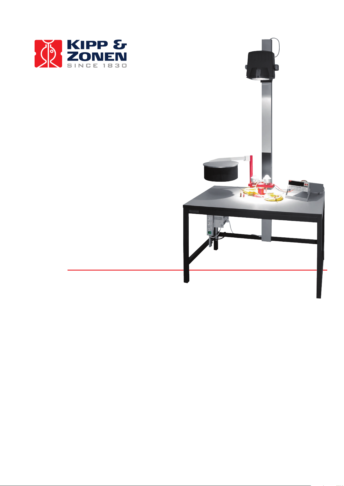
The calibration facility must be built up in the following order. The step-by-step procedure is illustrated in
the figures below.
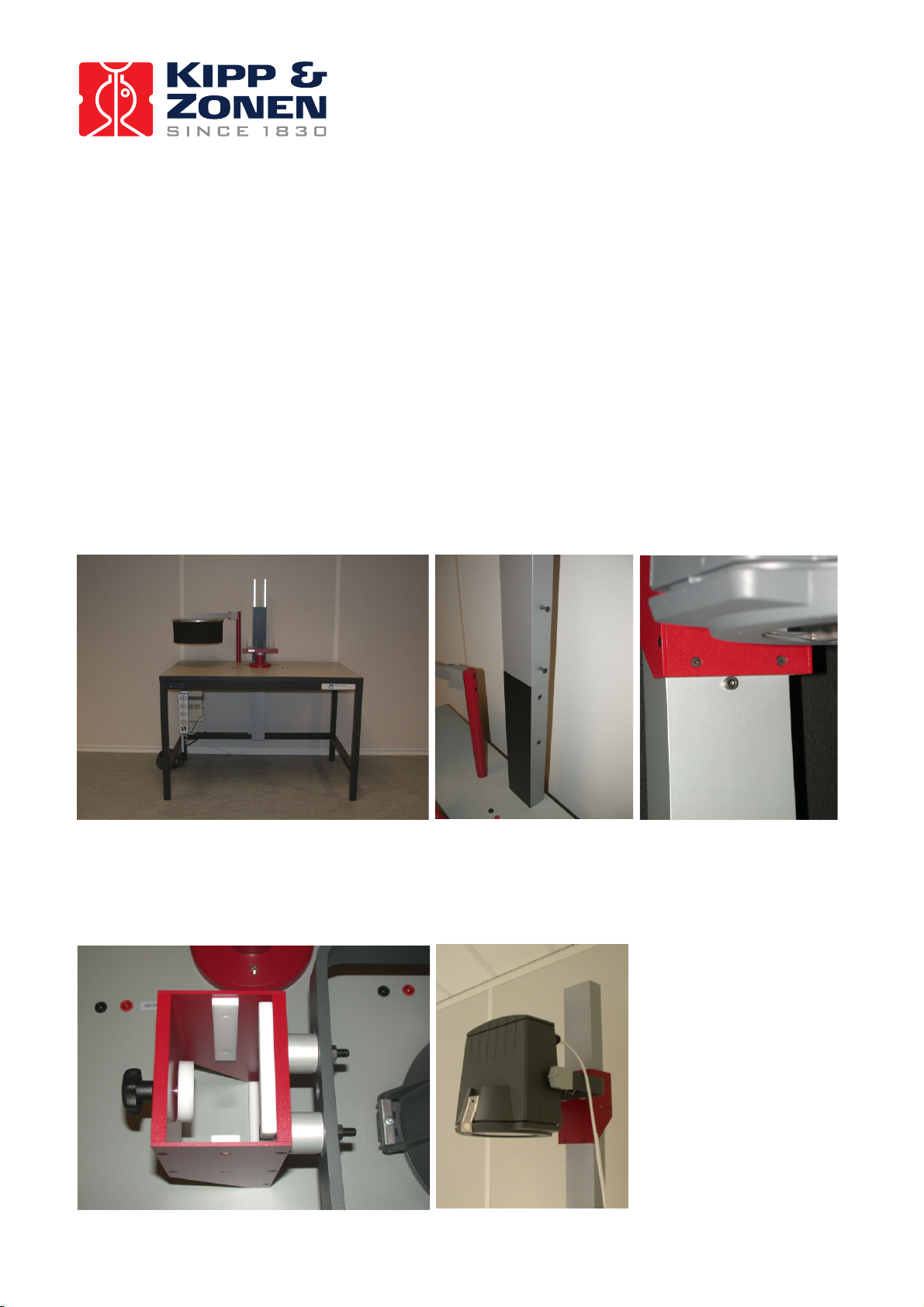
Step 1 Mount the lamp pillar on the table and tightly secure it with the 4 countersunk bolts. The limit cam
should be visible at the front side of the lamp pillar.
figure 1 Calibration table with lamp pillar
Step 2 Slide the lamp mounting bracket over the lamp pillar and place the white clamping disk inside the
bracket.
figure 2 Lamp mounting bracket slid over the lamp pillar
Page 9

CFR manual
8
Step 3 Remove the mains plug from the lamp housing power cable (if fitted) and pass the cable through
the lamp mounting pillar and cable gland.
figure 3 Lamp cable passed trough the lamp pillar
Step 4 Electrical connection of the lamp to the voltage stabilizer
115 VAC / 60 Hz Calibration Facility
The 115 VAC / 60Hz version of the CFR has all the electronic components for powering the bulb integrated
into the lamp housing. Re-fit the plug and connect directly to a suitable mains outlet socket. Connect the
voltmeter power cable to a suitable mains outlet socket.
230 VAC / 50 Hz Calibration Facility
Connect the lamp power cable to the voltage stabilization unit, as shown in figure 4. Fit the metal cover
and connect the voltage stabilizer and voltmeter power cables to suitable mains outlet sockets.
figure 4 Cable wires connected to the voltage stabilizer terminals
Warning: To prevent electric shock during installation, all electrical devices
must be disconnected from the mains power.
Label
Function
Cable
Wire color
1 in
Neutral
Mains
Blue
2 in
Phase 230 VAC
Mains
Brown
Protective Earth
Mains
Yellow/Green
Earth
Table
Yellow/Green
3 out
Neutral / Earth
Lamp
Blue and
Yellow/Green
4 out
Phase 230 VAC
Lamp
Brown
5 out
- - -
Page 10

CFR manual
9
Step 5 Connect the red and black signal measurement cables to either the back or front input terminals of
the voltmeter and to the signal output terminals near the lamp pillar.
figure 5 Signal cables between voltmeter and signal output terminals
Step 6 The installation will be complete when the mains power cord is connected to an AC power outlet.
The lamp of the 230 VAC / 50 Hz Calibration Facility the lamp can be turned on and off using the switch on
the power strip.
Finally the correct lamp height should be determined by measuring the irradiance with a reference
pyranometer at the left or right position of the turntable. Adjust the lamp height such that the irradiance
should be in the range 500 – 600 W/m
2
.
figure 6 Complete calibration facility
Page 11

CFR manual
10
2.3 Maintenance
In general, the manual calibration facility requires little maintenance apart from keeping it clean and
checking that mountings, fittings and electrical connections are secure.
2.3.1 Lamp
Regular cleaning of both sides of the lamp window is necessary to maintain even illumination.
Open the cover of the lamp by releasing the latches. Remove
the old bulb using a piece of soft cloth and dispose of it
according to local regulations. Take a new bulb from its
package and be sure to only hold it by the base. Handling the
quartz envelope may leave permanent marks on the surface,
so always use a soft, clean cloth. Fit the 2-pin base of the new
bulb into the holder in the middle of the lamp reflector. It only
locates in one orientation and should snap into the lamp
holder when using a minimum amount of force. Close and
secure the lamp cover before switching on the power.
figure 7 230 VAC/ 50 Hz calibration facility
2.3.2 Maintenance and recalibration of the reference pyranometer
On a regular basis the pyranometer dome should be cleaned using alcohol, or clean water. The reference
should be kept in a clean, dry and dark place at stable temperature when not in use. The desiccant should
be checked regularly and changed when necessary. It can be recalibrated at the World Radiation Centre
(Davos, Switzerland), at a Regional Radiation Centre, or at Kipp & Zonen. Addresses of Radiation Centres
can be found in Annex III to this manual. The reference pyranometer should be of similar type
(construction) to the test pyranometer and of equivalent or higher standard.
It can be convenient to have two of each reference type, so that indoor calibrations can continue whilst the
other reference is at a Radiation Centre for recalibration. When the recalibrated reference becomes
operational it is advised to document the change of your radiation scale by checking the old reference
against the new reference. If the scale change is < 1% you can accept the new value as being the most
Warning: When cleaning the window or changing the bulb of the calibration
lamp for maintenance purposes, the calibration facility should be
disconnected from the mains power.
The bulb is pressurized and very hot during operation. Allow it to cool down
before handling.
Page 12

CFR manual
11
“fresh” value. If the scale change is more than 1%, critical examination of the radiation centre procedures
for old and new references is necessary.
Page 13

CFR manual
12
There are several procedures for transferring calibration values from a narrow field of view instrument
(pyrheliometer) to a wide field of view instrument (pyranometer). For example the direct component of the
solar radiation can be eliminated temporarily from the pyranometer by shading the whole outer dome of the
instrument with a disk. However, there is no thermal equilibrium with this method and some models of
pyranometer show significant zero-offset drift.
An alternative procedure maintains the test pyranometer in its normal operating condition. This 'component
sum' method involves measuring the direct component of the solar radiation with a pyrheliometer and the
diffuse component with a shaded pyranometer, and adding together the two values to obtain the global
radiation. As, during a clear day, the diffuse radiation is only about 10% of the global radiation, the
sensitivity of the second pyranometer does not need to be known very accurately. Both procedures are
suitable to obtain a working standard pyranometer. This method is extensively described in international
standard ISO 9846.
Transfer from the working standard pyranometer to other pyranometers can be done in sunlight. The
pyranometers must be mounted side by side so that each views the same sky dome. It is desirable to
integrate, or average, the outputs over a period of time and then compute the calibration constants on the
basis of these averages. This reduces the errors due to changing parameters during the day.
Transfer from a working standard pyranometer in the laboratory is only reliable when both pyranometers
are of the same construction and have similar optical characteristics. Kipp & Zonen can recalibrate
pyranometers according to this method.
2.3.3 Spare Parts Specification
This section provides the article numbers for ordering spare parts for the Calibration Facility.
Part Description Part No.
Lamp Housing : 230 VAC / 50Hz Version 2654116
: 115 VAC / 60Hz Version 2654117
Bulb (115 & 230 VAC) : Philips CDM-T 150 W / 942 2603864
Lamp stabilizer (230 VAC) : MCB Industries , Model 250 VA / 50Hz 2681060
Voltage measurement device : Keithley Instruments, model 2000 4902212
Page 14

CFR manual
13
3 Calibration operation
The indoor calibration procedure, according to ISO 9847 Appendix III, is based on a side-by-side
comparison with a reference radiometer under a stable artificial sun. Kipp & Zonen uses a 150 W MetalHalide high-pressure gas discharge lamp with voltage stabilisation. Behind the lamp is a reflector with a
diameter of 16.2 cm. The reflector is 115 cm above the radiometers producing a vertical beam. The
irradiance at the radiometers is approximately 500 W/m².
To minimise stray light from the walls and the operator, the light is restricted to a small cone around the two
radiometers. The unknown test radiometer 'T' and the reference radiometer 'R' are placed side-by-side on a
small table. The table can rotate to interchange the positions (1 and 2) of the radiometers. The lamp is
centred on the rotating axis of this table. Actually there is no normal incidence of the radiation, but the
angle of incidence is the same for both radiometers (3°) so this cannot give rise to errors. The two
radiometers are not levelled with the adjustable feet, but placed on their bases. The effect of the small
beam tilt is negligible (compare cos. 3° = 0.9986 and cos. 4° = 0.9976).
Once the Calibration Facility has been installed calibration is quick and simple, but the procedure must be
carried out carefully and thoroughly. Section 3.1 describes the procedure and 3.2 gives step-by-step
instructions to follow. The philosophy behind the calibration is given in 3.3. In 3.4 an example of a
calibration form is given and the form is shown in Annex I.
Wherever output voltages are indicated, R refers to the reference and T refers to the test pyranometer.
When dark signals or offsets are indicated, the "E" symbol is used. Measurements in position 1 are
indicated by "1" (see paragraph on turntable), measurements in position 2 are indicated by "2". The symbol
"S" refers to sensitivity.
3.1 Description of the procedure
The reference pyranometer and the test pyranometer are placed side-by-side on the turntable in position 1.
The table can turn in order to exchange positions. The lamp illuminates both pyranometers with an intensity
of approximately 500 Watts per square meter.
After illuminating for one minute, the output voltages of both pyranometers are measured shortly after each
other with the voltmeter. The obtained values are called R and T. Next, a shield covers both pyranometers,
so that they do not receive any light. After one minute, the output voltages of both pyranometers are again
measured. The values obtained, called ‘zero offsets’, are RE and TE respectively. The order of magnitude
of this offset for a Kipp & Zonen pyranometer is a few W/m
2
. For pyranometers from other manufacturers, it
could be larger. These zero offsets must be subtracted from the values R and T. The resulting values are
R1 (equals R-RE) and T1 (equals T-TE).
Page 15

CFR manual
14
The possibility of making errors due to inhomogeneous light is still present. Therefore, the positions of the
pyranometers are interchanged, to position 2, by rotating the turntable, and the procedure is repeated. The
resulting values of this second measurement are called R2 and T2.
The sensitivity ST of the test pyranometer can now be calculated based on the known sensitivity of the
reference pyranometer SR:
)21(
)21(RRTT
SRST
+
+
⋅=
(Formula 1)
Finally, a check on errors and lamp stability can be done, using the information of the output of the
pyranometers. If the stability is not sufficient, the calibration should be rejected. The rule is that the
calibration has not succeeded if the following expression is outside its boundaries:
0.98 <
)22(
)11(TRTR⋅⋅
< 1.02 (Formula 2)
This expression is sensitive to:
• read-out errors by the operator;
• accidental shading of one pyranometer;
• a non-perfect interchange of position;
• light field instability.
Lamp drift influences the result of the expression, although the effect on the calculated sensitivity ST is
negligible due to the near simultaneous read-outs.
Page 16

CFR manual
15
3.2 Description of the procedure step-by-step
1. Switch on the lamp and the voltmeter.
2. Place the reference and test pyranometers in the calibration room, outside the lamplight, in order to
let their temperatures stabilize. Allow 2 hours for the test pyranometer to stabilize if it has been
outdoors.
3. Allow 20 minutes for the lamp to stabilize.
4. Put a test pyranometer and the reference in position marked with
reference. Check that the detector surface heights are the
same.
5. Darken the pyranometers with the shading mechanism and wait 2
minutes.
6. Expose the pyranometers to light.
7. After exactly one minute note the outputs of the reference and test
pyranometers. Write them down on the calibration form.
8. Darken the pyranometers.
9. Exactly one minute after darkening, note the outputs of the
reference and test pyranometers. Write them down on the
calibration form.
10. Rotate the turntable so that the pyranometers are in opposite
position, in the dark.
11. Expose the pyranometers to the light.
12. After exactly one minute note the outputs of the reference and test
pyranometers. Write them down on the calibration form.
13. Darken the pyranometers.
14. Exactly one minute after darkening, note the outputs of the
reference and test pyranometers. Write them down on the
calibration form.
15. Calculate the calibration factor according to the procedure that is
described on the calibration form.
16. Check if the lamp stability has been sufficient, according to the
procedure that is described on the calibration form.
17. For multiple calibrations start again at step 4.
figure 8 Different positions of the turntable
and shutter during the calibration procedure
Page 17

CFR manual
16
3.3 Calibration uncertainty
The main purpose of the calibration procedure is to perform a one-to-one comparison of the reference
pyranometer and the test pyranometer. In order to achieve this, both pyranometers need to be exposed to
exactly the same irradiance, under the same circumstances.
There are a number of error sources that could affect the calibration measurement. Potential sources of
error are: Lamp instability, pyranometer zero offsets (A and B), voltmeter offset, differences in sensor
height and tilting of the pyranometers. These error sources are described below.
The method of performing the calibration, and the subsequent calculations, have been chosen such that
the effects of all these error sources have been minimised.
3.3.1 Instability of the lamp output power
Instability of the lamp output power due to mains voltage variations and changes in the light field is
fortunately only a secondary source of error. By using formula 2 one can easily assess the total lamp power
instability and calibrations where the deviation is greater than 2 % should be rejected.
3.3.2 Pyranometer offsets
Pyranometer offsets cause an output from the instrument, even when no light is present. These offsets are
corrected for during the calibration procedure by performing the dark measurements and are taken into
account in Formula 1.
ISO 9060 specifies two kinds of offsets; "zero offset a" which results from exchange of thermal radiation
between the pyranometer and its surroundings, and "zero offset b" which results from changes in the
ambient air temperature.
The offsets are basically caused by the fact that the pyranometer incorporates a thermal sensor, which is
sensitive to all heat flows. A high offset can usually be cured by waiting. It will settle down slowly.
Important note!
1. Pyranometers should be kept out of the lamplight when exposure is not necessary.
2. Pyranometers must be operated in a thermally stable environment during calibration.
More detailed information about zero offsets is explained in the general pyranometer manual.
Page 18

CFR manual
17
3.3.3 Voltmeter offset
Theoretically, the voltmeter can cause a zero offset or drift. Short-circuiting the voltmeter input with a
resistance equal to the pyranometer’s impedance can check the zero offset. The voltmeter might change
sensitivity over the years. Generally it should be regularly recalibrated, as for all test and measurement
instruments. Because of the fact that the calibration is a relative measurement, the voltmeter sensitivity is
cancelled out of the equations. Only the voltmeter linearity and short term drift must be good.
3.3.4 Tilting of the pyranometers
Tilting of the pyranometers, and also the related possibility of light rays that fall in at an angle other than
perpendicular, is not a significant error source. This can easily be shown by comparing the cosine values of
0° and 3° angles. These differ by only 0.1%.
3.3.5 Differences in sensor height and geometry
As stated earlier in this chapter, the main purpose of the calibration procedure is to perform a one-to-one
comparison of the reference pyranometer and the test pyranometer, which should ideally be of the same
model. In that case the height and geometry of both the reference and the test pyranometers are exactly
the same. In general, errors in height are the most serious threats to measurement accuracy and should be
checked with each calibration.
Note that for side-by-side calibrations outdoors the sensor’s heights are less critical because the light
source )the sun) is distant and the intensity gradient is small.
3.3.6 Calibration repeatability and overall uncertainty
From experience, the agreement of the calculated values of sensitivity (S) over a number of consecutive
measurements of the same test pyranometer shows repeatability within 0.5% percent.
The overall calibration uncertainty of the test pyranometer is estimated to be < 1% compared with the
calibrated value of a reference Pyranometer of similar type.
Page 19

CFR manual
18
3.4 Calibration Form
An example of a calibration form is given below.
Test pyranometer model:
CMP 6
Serial number:
060002
Reference pyranometer model:
CMP 6
Serial number:
060001
Sensitivity: 10.00 V/Wm
-2
(SR)
Calibration performed by:
J. Smith
Date: 20 September 2006 Signature
Reference pyranometer
Test pyranometer
Position 1
Illuminated
R 1980
T 2980
Darkened
RE 5
TE 10
R1=R-RE 1975
T1=T-TE 2970
Position 2
Illuminated
R 2100
T 2820
Darkened
RE 2
TE 8
R2=R-RE 2098
T1=T-TE 2812
Test pyranometer sensitivity
)21(
)21(
RR
TT
SRST
+
+
⋅=
14.20 V/Wm
-2
Lamp stability
0.98 <
)22(
)11(TRTR⋅⋅
< 1.02 0.994 OK/Rejected
Page 20

CFR manual
19
4 Principle components and specifications of the facility
The Calibration Facility consists of a number of parts. These are described in the following paragraphs.
4.1 Table
The table serves for mounting the lamp, the turntable, the voltage stabilizer (230 VAC version) and the
shading mechanism. Additionally, it can serve as a worktable and has clamps for connecting the reference
pyranometer signal wires, the test pyranometer signal wires and the voltage meter wires. During
calibration, the voltmeter is used alternately to measure both the reference pyranometer signal and the test
pyranometer signal.
In order to reduce light reflections, the table has a gray finish.
4.2 Turntable
The turntable serves for mounting the test pyranometer and the reference pyranometer. By rotating the
turntable, the positions of these two can be precisely interchanged.
The two available positions are called position 1 and 2. In position 1, the reference is at the left, as seen
standing in front of the Calibration Facility. In position 2, the reference is at the right.
The interchange of position during calibration is necessary because the light coming from the lamp is not
uniformly distributed across the surface in which the pyranometers are positioned.
In its standard form, the turntable is suitable for
installation of Kipp & Zonen pyranometers models
CM 6B, 11, 11B, 21, 22 and 31 and the successor
models CMP 6, CMP 11, CMP 21 and CMP 22.
Note: there is only one position in which the
pyranometers are properly supported by the
turntable pillars.
In order to change the voltmeter input signal from
the test pyranometer to the reference pyranometer,
a switch is incorporated in the turntable base.
For calibration of other Kipp & Zonen radiometers,
or pyranometers from other manufactures, a range
of adaptors is available.
figure 9 Turntable with reference pyranometer
Page 21

Average Life
12000 hrs
Lamp Voltage
90 V
Color Temperature
4200 K
Initial Lumens
12700
CFR manual
4.3 Shading mechanism
The shading mechanism serves to obtain the dark (zero-offset) signal of the pyranometers and the
measurement chain. The shading mechanism blocks all light illuminated from the lamp.
4.4 Lamp mounting pillar
The lamppost serves to position the lamp at a certain height above the pyranometers. In view of the fact
that the packaging has to stay within certain limits, the lamppost consists of two parts. The lower part is
painted black in order to avoid reflections of the lamp.
4.5 Lamp housing
4.5.1 115VAC/60 Hz Calibration Facility
The 115 VAC / 60Hz calibration lamp is a PAR CDM luminaire, constructed of cast
aluminium with non-corroding hardware and fittings.
4.5.2 230VAC/50 Hz Calibration Facility
The 230 VAC / 50Hz calibration lamp is a medium-sized, high-grade, rotationsymmetrical floodlight with a narrow beam.
4.6 Lamp bulb
The lamp serves to generate an input signal for comparing the pyranometer responses. The calibration of
the reference is usually done outdoors under sunlight. It should be noted that if the reference and test
pyranometers are of the same type, neither the spectrum nor the intensity of the calibration lamp need to
exactly simulate sunlight because both pyranometers will be affected similarly.
Product Identification Philips MasterColor CDM-T 150W/942 G12 T6 1CT
Power 150 W
Color Description 942 Cool White
Design Mean Lumens 8900
20
Page 22

CFR manual
21
4.7 Voltage Stabilization
The voltage stabilizer provides a highly stable voltage to the lamp. For calibration it is necessary to have a
reliable voltage because variations in lamp output can affect the result of the calibration slightly. In the final
calculation there is a check on read-outs and lamp stability. This is shown in chapter 3. For the 230 VAC /
50Hz version the voltage stabilizer is mounted underneath the table. The 115 VAC / 60Hz facility has the
stabilisation circuitry built into the lamp.
4.8 Voltmeter
The voltmeter shown in figure 10 serves to measure the
output of the pyranometers. The specific type of voltmeter has
been selected for its capability to measure small microvolt
signals with high stability and low offsets. In the final
calibration calculation, the absolute accuracy of the voltmeter
is eliminated as a parameter, as long as the readout is linear
and repeatable.
It is recommended to set the voltmeter to measure on the 100
mV scale with an accuracy of 3 digits. To ensure a steady
value of the output signal, the sampling rate should be set to
medium with a moving average filter over 100 samples. fi
gure 10 Voltmeter
4.9 Switch and clamps
The switch located on the turntable changes the input of the voltmeter from the reference pyranometer to
the test pyranometer. The spring clamps located on the table connect the signal wires of the two
pyranometers to the switch.
4.10 Reference pyranometer
The reference pyranometer used for calibration is normally delivered with the Calibration Facility, selected
from optional list to suit the test pyranometers to be recalibrated. It should normally be of the same type as
the test pyranometers or of a higher class but similar construction. The reason for this is that for similar
types, there are no errors introduced due to differing instrument characteristics. It is therefore suggested to
obtain a reference for each type that is in use.
It is possible to calibrate other types of pyranometers that are not the same as the reference. However, it
should be noted that the estimated calibration transfer accuracy could be lower. This has to do with the fact
that the surface areas of the detectors, spectral selectivity, non-linearity, time constants and other factors
may differ.
The reference pyranometer should be kept in a clean, dry and dark place in order to avoid unnecessary
aging and the desiccant checked regularly. Under field conditions, the change in sensitivity should be less
than ± 1% per year. Properly stored, the stability should be ± 0.25% per year.
Recalibration can be done either at Kipp & Zonen, at a Regional Radiation Centre, or (with the highest
accuracy) at the World Radiation Center (WRC) in Davos, Switzerland.
Page 23

CFR manual
22
The Kipp & Zonen reference pyranometers are calibrated at the WRC with the sun and sky as the radiation
source. As a consequence, in principle, the calibration values obtained for test pyranometers when using
the CFR are related to the same outdoor conditions as in Davos. The specific conditions are given in the
extended calibration certificate that accompanies the reference pyranometer. A small correction is applied
to convert from the solar elevation angle at the time of the reference calibration, to normal incidence
(vertical) radiation, as used in the CFR.
4.11 Mountings for other radiometers
A range of optional turntables and adapters is available for mounting other Kipp & Zonen radiometers and
some models of pyranometers from other manufacturers. These can be easily be exchanged with the
standard Kipp & Zonen mounting provided with the CFR.
4.12 Stopwatch
The stopwatch provides accurate timing of the calibration. It is necessary to perform the calibration with the
steps of the procedure timed as exactly as possible to overcome the fact that the response time of some
pyranometers is in the order of magnitude of 2 minutes for 99% response. Good timing is the key to optimal
repeatability.
Page 24

CFR manual
23
5 Frequently asked questions
□ Can I calibrate pyranometers from different manufacturers with the CFR?
The CFR is a universal calibration facility using a standardized calibration method that can be applied to
any other pyranometer model. Although one should take into account the basic principles of uniformity
between the test and reference pyranometer and ensuring equivalent detector heights.
□ Can I calibrate a Kipp & Zonen pyranometers using a higher standard Kipp & Zonen reference
pyranometer?
Most Kipp & Zonen pyranometers have a similar sensor geometry, therefore can be calibrated with a model
of a higher class. Kipp & Zonen offers different mounting adapters to accommodate pyranometers that do
not fit to the standard mounting bracket.
Page 25

CFR manual
24
Appendix I: Calibration Form for pyranometers
Test pyranometer model :
………………………..
Serial number :
………………………..
Reference pyranometer model :
………………………..
Serial number :
………………………..
Sensitivity :
………………………..
V/Wm
-2
(SR)
Calibration performed by :
………………………..
Date :
………………………..
Signature :
………………………..
Reference pyranometer
Test pyranometer
Position 1
Illuminated
R :
………………..
T :
………………..
Darkened
RE :
………………..
TE :
………………..
R1 = R-RE :
………………..
T1 = T-TE :
………………..
Position 2
Illuminated
R :
………………..
T :
………………..
Darkened
RE :
………………..
TE :
………………..
R2 = R – RE :
………………..
T2 = T – TE :
………………..
Test pyranometer sensitivity
)21(
)21(
RR
TT
SRST
+
+
⋅=
:
………………..
V/Wm-2
Lamp stability
0.98 <
)22(
)11(TRTR⋅⋅
< 1.02 :
………………..
OK/Rejected
Page 26

CFR manual
25
Appendix II: Pyranometer Classification According to WMO Guide 1996
Characteristics
CMP 22
CMP 21
CMP 11
CMP 6
High
quality
Good
quality
Moderate
quality
ISO 9060 classification
Secondary
Standard
Secondary
Standard
Secondary
Standard
First
Class
Secondary
Standard
First
Class
Second
Class
Response time (95 percent
response)
5 s
5 s
5 s
18 s
< 15 s
< 30 s
< 60 s
Zero offset:
(a) Response to 200 W/m
2
net thermal radiation
(ventilated)
(b) Response 5 K/h change
in ambient temperature
± 3 W/m
2
± 1 W/m
2
± 7 W/m
2
± 2 W/m
2
± 7 W/m
2
± 2 W/m
2
± 15 W/m
2
± 4 W/m
2
± 7 W/m
2
± 2 W/m
2
± 15 W/m
2
± 4 W/m
2
± 30 W/m
2
± 8 W/m
2
Resolution (smallest detectable
change)
± 1 W/m2
± 1 W/m2
± 1 W/m2
± 1 W/m2
± 1 W/m2
± 5 W/m2
± 10 W/m2
Stability (change per year,
percentage of full scale)
< 0.5
< 0.5
< 0.5
< 1
± 0.8
± 1.5
± 3.0
Directional response of beam
radiation
(The range of errors caused by
assuming that the normal incidence
responsivity is valid for all
directions when measuring, from
any direction, a beam radiation
whose normal incidence irradiance
is 1000 W/m
2
)
± 5 W/m2
± 10 W/m2
± 10 W/m2
± 20 W/m2
± 10 W/m2
± 20 W/m2
± 30 W/m2
Temperature response (percentage
of maximum due to any change of
ambient temperature within an
interval of 50 K)
± 0.5
-200C-+500C
± 1
-200C-+500C
± 1
-100C-+400C
± 4
-100C-+400C
± 2
± 4
± 8
Non-linearity (percentage deviation
from the responsivity at 500 W/m
2
due to any change of irradiance
within the range 100 to 1000 W/m
2
)
± 0.2
± 0.2
± 0.2
± 1
± 0.5
± 1
± 3
Spectral sensitivity (percentage of
deviation of the product of spectral
absorptance and spectral
transmittance from the
corresponding mean within the
range of 0.3 to 3 µm)
± 2
± 5
± 10
Tilt response (percentage deviation
from the responsivity at 0° tilt,
horizontal, due to change in tilt
from 0° to 90° at 1000 W/m
2
irradiance)
± 0.2
± 0.2
± 0.2
± 1
± 0.5
± 2
± 5
Achievable uncertainty, 95 percent
confidence level
Hourly totals
Daily totals
1 %
2 %
2 %
5 %
3%
2%
8%
5%
20%
10%
Page 27

CFR manual
26
Appendix III: List of World and Regional Radiation Centres
World Radiation Centres
Davos (Switzerland)
St. Petersburg (Russia) (data centre only)
Region I (Africa)
- Cairo (Egypt)
- Khartoum (Sudan)
- Kinshasa (Dem. Rep. of the Congo)
- Lagos (Nigeria)
- Tamanrasset (Algeria)
- Tunis (Tunisia)
Region II (Asia)
- Pune (India)
- Tokyo (Japan)
Region III (South America)
- Buenos Aires (Argentina)
- Lima (Peru)
- Santiago (Chile)
Region IV (North and Central America)
- Toronto (Canada)
- Boulder (United States)
- Mexico City (Mexico)
Region V (South-West Pacific)
- Melbourne (Australia)
Region VI (Europe)
- Budapest (Hungary)
- Davos (Switzerland)
- St. Petersburg (Russian Federation)
- Norrköping (Sweden)
- Trappes/Carpentras (France)
- Uccle (Belgium)
- Lindenberg (Germany)
Page 28

CFR manual
27
Appendix IV: Recalibration service
Pyranometers, Albedometers, Pyrgeometers, UV-Radiometers &
Sunshine Duration Sensors
Kipp & Zonen solar radiation measurement instruments comply with the most demanding international
standards. In order to maintain the specified performance of these instruments, Kipp & Zonen recommends
calibration of their instruments every two years.
This can be done at the Kipp & Zonen factory. Here, recalibration to the highest standards can be
performed at low cost. Recalibration can usually be performed within four weeks. If required, urgent
recalibration can be accomplished in three weeks or less (subject to scheduling restrictions). Kipp & Zonen
will confirm the duration of recalibration at all times. Please note that special quantity recalibration
discounts are available for instruments of the same type.
Page 29

Our customer support remains at your disposal for any maintenance or repair, calibration,
supplies and spares.
Für Servicearbeiten und Kalibrierung, Verbrauchsmaterial und Ersatzteile steht Ihnen unsere
Customer Support Abteilung zur Verfügung.
Notre service ‘Support Clientèle’ reste à votre entière disposition pour tout problème de
maintenance, réparation ou d’étalonnage ainsi que pour les accessoires et pièces de rechange.
Nuestro servicio de atención al cliente esta a su disposición para cualquier actuación de
mantenimiento, reparación, calibración y suministro de repuestos.
HEAD OFFICE
Kipp & Zonen B.V.
Delftechpark 36, 2628 XH Delft
P.O. Box 507, 2600 AM Delft
The Netherlands
T: +31 (0) 15 2755 210
F: +31 (0) 15 2620 351
info@kippzonen.com
SALES OFFICES
Kipp & Zonen France S.A.R.L.
7 Avenue Clément Ader
ZA Ponroy - Bâtiment M
94420 Le Plessis Trévi
France
Kipp & Zonen Asia Pacific Pte. Ltd.
81 Clemenceau Avenue
#04-15/16 UE Square
Singapore 239917
Kipp & Zonen USA Inc.
125 Wilbur Place
Bohemia
NY 11716
United States of America
Go to www.kippzonen.com for your local distributor or contact your local sales office
se
+33 (0) 1 49 62 41 04
T:
F: +33 (0) 1 49 62 41 02
kipp.france@kippzonen.com
T: +65 (0) 6735 5033
F: +65 (0) 6735 8019
kipp.singapore@kippzonen.com
T: +1 (0) 631 589 2065
F: +1 (0) 631 589 2068
kipp.usa@kippzonen.com
Passion for Precision
 Loading...