

Page 1
2 AP
2-Axis Sun Tracker / Positioner Gear Drive
Instruction Manual
Page 2

IMPORTANT USER INFORMATION
IMPORTANT USER INFORMATION
Reading this entire manual is essential for full understanding of the proper
use and safe operation of this product
Should you have any comments on this manual we will be pleased to receive them at:
Kipp & Zonen B.V.
Delftechpark 36
2628 XH Delft Holland
P.O. Box 507 2600 AM Delft Holland
Phone +31 (0)15 2755210
Fax +31 (0)15 2620351
Email info@kippzonen.com
Web www.kippzonen.com
Kipp & Zonen reserves the right to make changes to the specifications without prior notice.
WARRANTY AND LIABILITY
Kipp & Zonen guarantees that the product delivered has been thoroughly tested to ensure that it meets its
published specifications. The warranty included in the conditions of delivery is valid only if the product has
been installed and used according to the instructions supplied by Kipp & Zonen.
Kipp & Zonen shall in no event be liable for incidental or consequential damages, including without
limitation, lost profits, loss of income, loss of business opportunities, loss of use and other related
exposures, however caused, arising from the faulty and incorrect use of the product.
User made modifications can affect the validity of the CE declaration.
COPYRIGHT
All rights reserved. No part of this publication may be reproduced, stored in a retrieval system or
transmitted in any form or by any means, without permission in written form from the company.
©
2005 KIPP & ZONEN
1
Page 3

IMPORTANT USER INFORMATION
Use the reserved place below to write down the version number of the supplied Win2AP operating
software. The software version number is given on the original CD-ROM label or can be retrieved
from the “about” pull down menu in Win2AP:
Manual version: 0706
Throughout the manual and inside the 2AP instrument symbols are used to indicate to the user
important information. The meaning of the symbols is as follows:
The exclamation mark within an equilateral triangle is intended to alert the user to the
presence of important operating, maintenance or safety information
Caution, risk of electric shock
Protective conductor terminal
Direct Current (DC)
Alternating Current (AC)
2
Page 4

IMPORTANT USER INFORMATION
DECLARATION OF CONFORMITY
According to EC guideline 89/336/EEC 73/23/EEC
We: Kipp & Zonen B.V.
Delftechpark 36
2628 XH Delft
The Netherlands
Declare under our sole responsibility that the product:
Type: 2AP Gear Drive
Name: Two-Axis Positioner and Tracker
To which this declaration relates is in conformity with the following European, harmonized and
published standards at date of this declaration:
EN 61326-1:2000
EN 61010-1:2001
Following the provisions of the directive:
EMC-directive : 89/336/EEC
Amendment to the above directive: 93/68/EEC
Low Voltage Directive 73/23/EEC
These conclusions are based on test reports:
1003/2AP/EMC
Delft,
March 03/15/02
ce-test PO box 563 2600 AN DELFT
B.A.H. Dieterink
President
KIPP & ZONEN B.V.
3
Page 5

IMPORTANT USER INFORMATION
4
Page 6

TABLE OF CONTENTS
TABLE OF CONTENTS
IMPORTANT USER INFORMATION ...................................................................................................................... 1
DECLARATION OF CONFORMITY ........................................................................................................................ 3
TABLE OF CONTENTS .......................................................................................................................................... 5
1 GENERAL INFORMATION............................................................................................................................. 7
1.1 INTRODUCTION TO THE 2AP ............................................................................................................... 7
1.2 MANUAL.................................................................................................................................................. 8
1.3 WIN2AP SOFTWARE.............................................................................................................................. 8
2 TECHNICAL DATA ......................................................................................................................................... 9
2.1 SPECIFICATIONS OF THE 2AP............................................................................................................. 9
3 SAFETY INFORMATION.............................................................................................................................. 11
3.1 POWER SUPPLY AND FUSE RATINGS ...............................................................................................11
3.2 DATA AND POWER CABLE CONNECTIONS.......................................................................................13
3.3 ENVIRONMENTAL CONDITIONS .........................................................................................................16
3.4 SUNTRACKER AND POSITIONER .......................................................................................................17
4 INSTALLATION AND SETUP ....................................................................................................................... 18
4.1 WIN2AP SOFTWARE.............................................................................................................................18
4.1.1 System Requirements................................................................................................................ 18
4.1.2 Installation.................................................................................................................................. 18
4.1.3 Win2AP Overview...................................................................................................................... 19
4.1.4 Selecting the 2AP Purpose........................................................................................................ 21
4.2 MINIMUM OPERATING AREA...............................................................................................................22
4.2.1 Installing the 360° Limit Option .................................................................................................. 24
4.3 MOUNTING THE 2AP ............................................................................................................................26
4.4 LEVELLING THE 2AP ............................................................................................................................28
4.5 ACCESSORY INSTALLATION...............................................................................................................29
4.5.1 Tripod Floor Stand..................................................................................................................... 29
4.5.2 Rear Mounting Plate .................................................................................................................. 31
4.5.3 Large Side Mounting Plate......................................................................................................... 34
4.5.4 Pointing and Shading Ball Assembly ......................................................................................... 37
4.5.5 Sun Sensor................................................................................................................................ 41
4.5.6 Attaching Instruments to the 2AP .............................................................................................. 45
4.5.7 Cold Weather Cover .................................................................................................................. 48
4.6 COMMISSIONING 2AP AS SUNTRACKER...........................................................................................49
4.6.1 Setting the Time......................................................................................................................... 49
4.6.2 Setting the Location................................................................................................................... 50
4.6.3 Start Suntracking ....................................................................................................................... 51
4.6.4 Sighting Adjustment without Sun Sensor ................................................................................... 51
4.6.5 Sighting Adjustment with Sun Sensor ........................................................................................ 52
4.7 COMMISSIONING 2AP AS POSITIONER .............................................................................................57
4.7.1 2AP Azimuth and Zenith Orientation.......................................................................................... 57
4.7.2 Mounting the 2AP as Positioner................................................................................................. 58
4.7.3 Adapting the 2AP Zenith Range ................................................................................................ 60
4.7.4 Configuring the 2AP for Positioner Purpose .............................................................................. 62
4.8 SAVING CONFIGURATION AS DEFAULT PARAMETERS ..................................................................64
5
Page 7

TABLE OF CONTENTS
5 OPERATION................................................................................................................................................. 66
5.1 RUN SUNTRACKER ..............................................................................................................................66
5.2 SUN SENSOR OBSERVATIONS...........................................................................................................68
5.3 RUN POSITIONER .................................................................................................................................68
5.3.1 Positioner Main Window ............................................................................................................ 68
5.3.2 Defining Instrument Targets....................................................................................................... 71
5.3.3 Target Types.............................................................................................................................. 74
5.3.4 Moving to Targets...................................................................................................................... 77
5.3.5 Manual Override ........................................................................................................................ 77
5.3.6 Monitoring 2AP Position During Operation ................................................................................ 77
5.3.7 On-line Help and Positioner Information .................................................................................... 78
5.4 CMD UTILITY .........................................................................................................................................79
5.4.1 CMD Utility Operation................................................................................................................ 79
6 REFERENCE INFORMATION...................................................................................................................... 82
6.1 PHYSICAL INTERFACE.........................................................................................................................82
6.2 SOFTWARE INTERFACE ......................................................................................................................82
6.2.1 Configuration Commands ..........................................................................................................83
6.2.2 Operation Commands................................................................................................................ 87
6.2.3 Status Commands ..................................................................................................................... 89
6.3 ERROR CODES .....................................................................................................................................92
6.4 GENERATING THE FED CHECK SEQUENCE .....................................................................................94
6.5 EVENT LOGS.........................................................................................................................................94
6.6 LOG ITEMS ............................................................................................................................................94
7 MAINTENANCE............................................................................................................................................ 98
8 SOLVING PROBLEMS ............................................................................................................................... 101
8.1 PROBLEM CHECK-LIST ......................................................................................................................102
8.2 TROUBLE SHOOTING.........................................................................................................................103
Appendix I............................................................................................................................................................ 105
6
Page 8
TECHNICAL DATA
1 GENERAL INFORMATION
1.1 INTRODUCTION TO THE 2AP
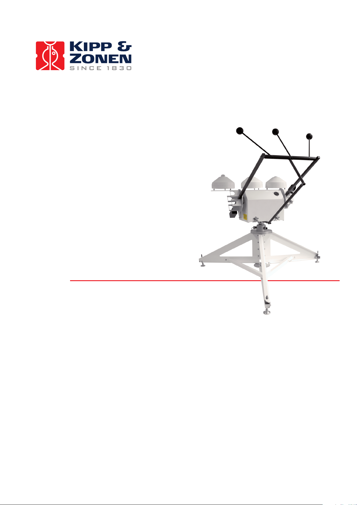
The 2AP two-axis tracker and positioner is an all-weather positioning platform used to point
specialized instruments at the sun’s movement across the sky or at stationary targets. It has been
designed to provide reliable, affordable positioning for small and medium sized payloads. Its
accuracy is excellent for solar monitoring applications.
When configured to operate as a solar tracker, unattended stand-alone operation is provided
through the 2AP’s embedded microcomputer-controlled azimuth and zenith positioning mechanism.
As a PC-based positioner, the 2AP is controlled and monitored by a full-time connection to a host
computer running the Win2AP software. Serial cable or modem interfacing can be used for
communications with the tracker.
The 2AP Gear Drive (2AP GD) is an all weather instrument providing optimal performance even in
the most harsh climates (from equatorial to Polar regions) and/or when the highest performance is a
necessity. The 2AP Gear Drive features high accuracy, resolution and repeatability, and great
torque.
A standard 2AP with no accessories is shown in Figure 1.1. Figure 1.2 shows the 2AP Gear Drive’s
most important parts.
Figure 1.1: 2AP Outline Dimensions.
7
Page 9

TECHNICAL DATA
Figure 1.2: 2AP Gear Drive most important parts.
1.2 MANUAL
The 2AP INSTRUCTION MANUAL is intended for customers who have purchased the 2AP Gear
Drive with some or all of the accessory items that can be used to enhance or expand its capabilities.
It includes all the information necessary to install and operate the 2AP for stand-alone and PCbased suntracking and positioning purposes.
1.3 WIN2AP SOFTWARE
The Win2AP software comprises a set of utility programs designed to support the use of the 2AP.
The software can be used to set up and run the 2AP as a suntracker or as positioner. The utilities
run on an IBM compatible computer connected to the 2AP RS232 serial port. The software is
intended for the use of the scientist using the 2AP and the technicians installing the 2AP. The
software has several functions:
• Post delivery check
• To aid the preparation of the 2AP installation and setup
• To provide on-screen guidance of the 2AP setup on location
• To configure the 2AP as a suntracker or positioner
• To facilitate sending commands to, and displaying responses from the 2AP
• To provide a tool for verifying the validity of connections to the 2AP
8
Page 10

TECHNICAL DATA
2 TECHNICAL DATA
2.1 SPECIFICATIONS OF THE 2AP
Table 1: Operating specifications of the 2AP.
Gear Drive
Temperature:
Standard 2AP
2AP with Cold Weather Cover
2AP with Cold Weather Cover and Heaters
Altitude To 2000m above sea level
Voltage 115/230 VAC (±10%),
Power 50VA Standard
Communication
Surge Protection power and heaters
Real Time Clock Accuracy 25 ppm - power off
Memory Back-up Battery Life 15 years with power on
Motor stepping motor
Motor Drive half/full step
Control Software Win2AP
Control open loop
Drive spur gear primary/
Rotation Limits optical switches (x4)
Reference Position optical switches (x2)
Accuracy
Repeatability
Resolution 0.0025°
Angular Velocity
Angular Acceleration
Torque 40 Nm
Payload 65 kg balanced
Rotation 90°/210º Zenith
(1)
1σ at constant temperature
(2)
1σ at constant temperature and for movement in the same direction
(3)
User programmable
(1)
(2)
<0.01°
(3)
up to 1.8°/sec
(3)
up to 3.6°/sec2
0° to +50°C
-20° to +50°C
-50° to +50°C
(no limit with 24V DC option)
60/50 Hz
24 VDC optional (23-26 VDC)
150VA with optional heater kit
200VA with extreme heater kit
RS-232, 3-wire, 8, N, 1
300 to 9600 baud
2 ppm - operating
6 months with power off
MS Windows™ based
double-involute worm final
<0.05°
540° Azimuth
(360° Azimuth limit option)
9
Page 11

TECHNICAL DATA
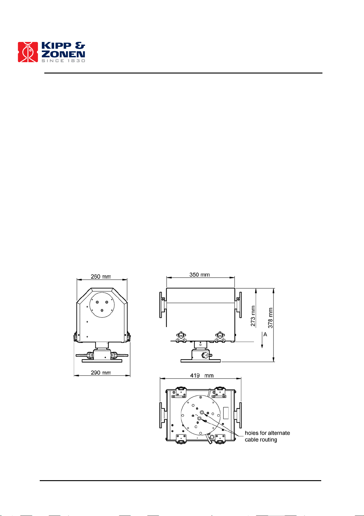
Table 2: 2AP Physical Dimensions.
Gear Drive
Length 35 cm (chassis only)
42 cm (including side mounting plates)
Width 29 cm
Height 38 cm
Weight 30 kg
10
Page 12
INSTALLATION AND SETUP
3 SAFETY INFORMATION
3.1 POWER SUPPLY AND FUSE RATINGS
Important: Power supply
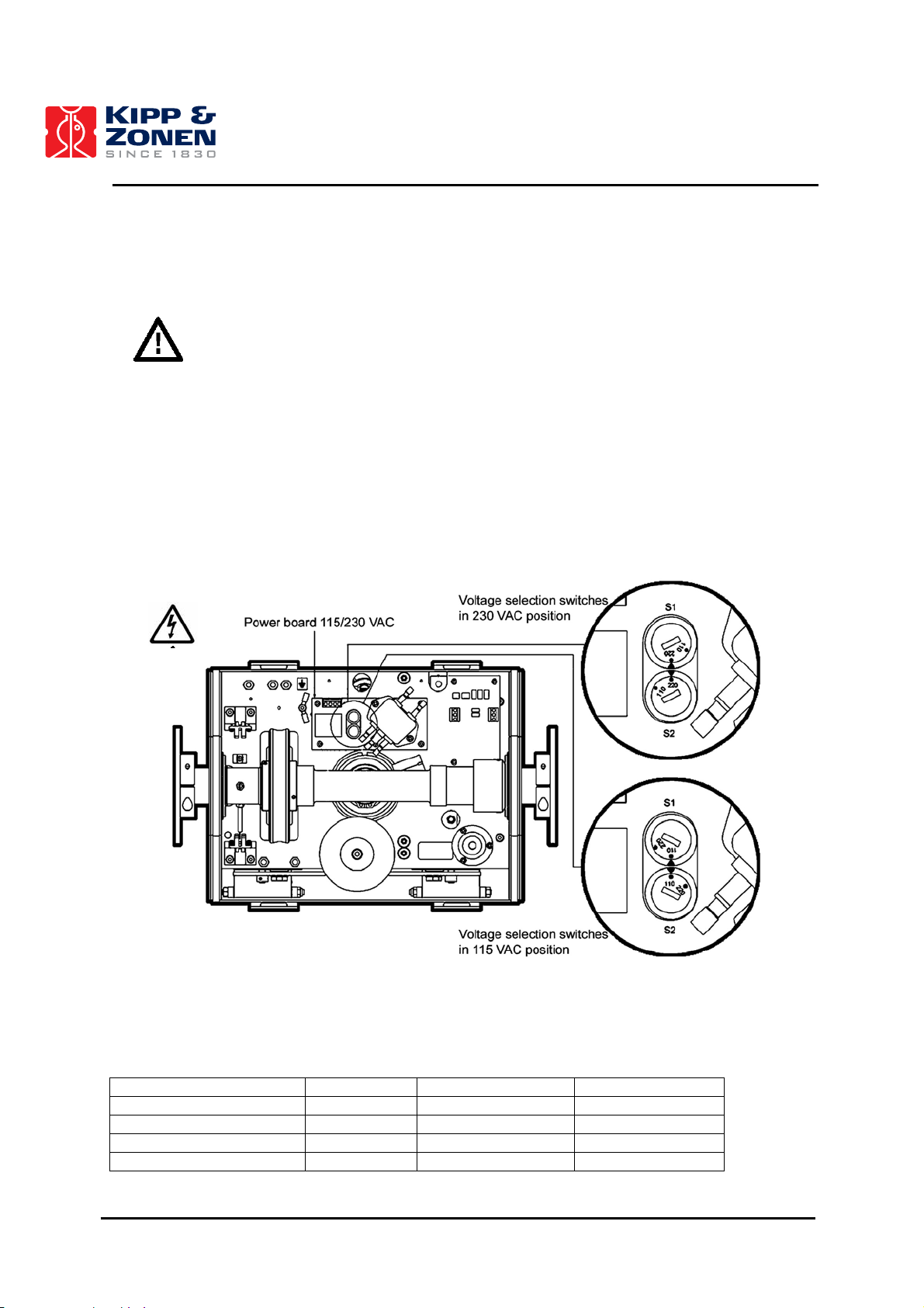
Prior to turning the 2AP (115/230 VAC version) power on, ensure that the voltage selection
switches for main power and for the optional heaters (figure 3.1) are in the correct positions to
match the incoming power supply and that the appropriately rated fuses are fitted.
As the voltage selection switches are located on the power board ensure that the 2AP power is
turned off before continuing. Use a screwdriver to turn the 115/230 VAC switches as necessary.
Although the switches on the power board read 110/220V, they are suited to 115/230 mains
voltage, respectively. The switches are qualified for equipment of protection class II VDE 0630 (6.3
A/250 V). The mains voltage and fuse ratings for 115/230 VAC and 24 VDC are shown in table 3.
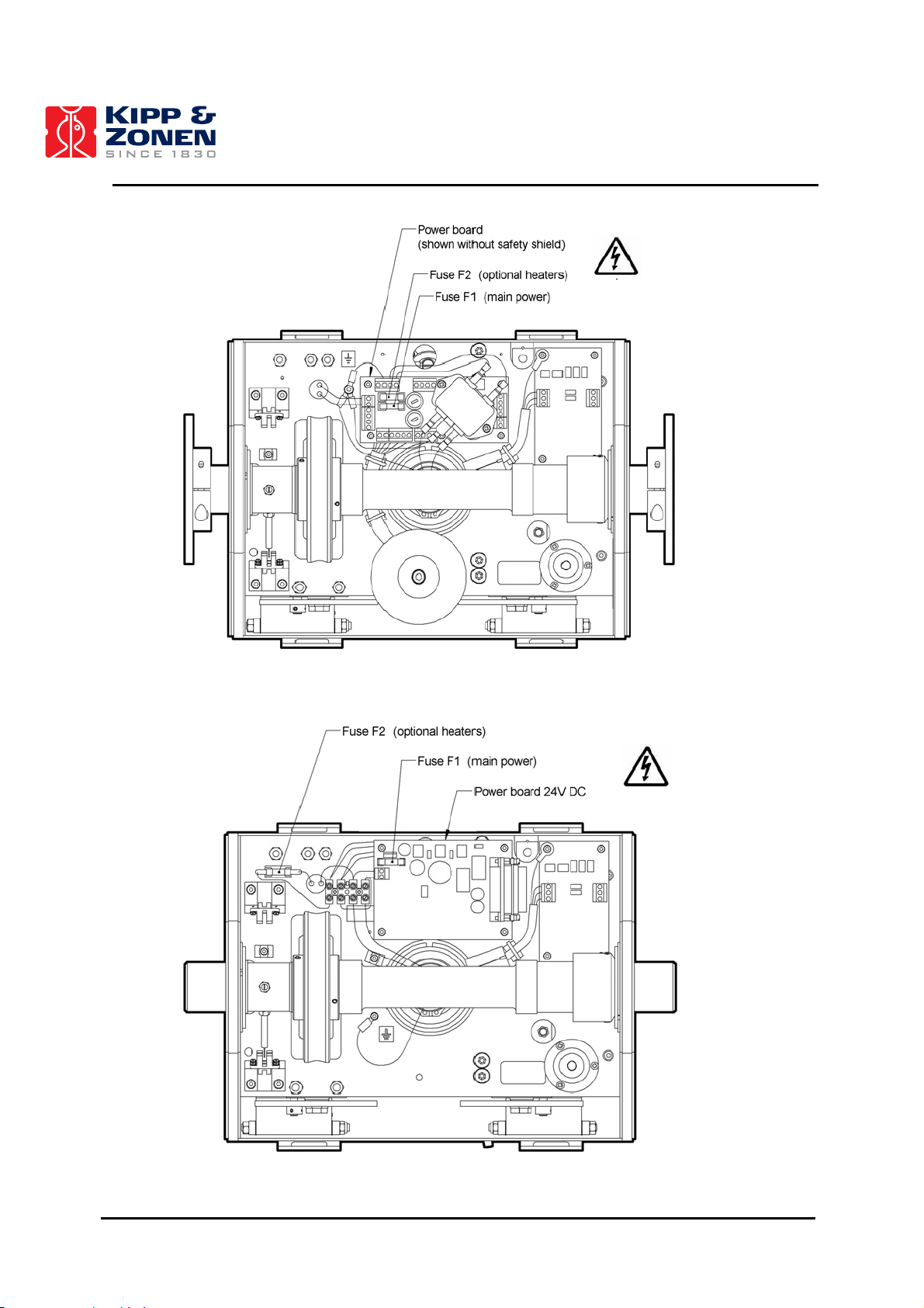
The fuses are according to IEC 60127-2, VDE, UL. The location of the fuses on the power board is
given in figures 3.2 and 3.3.
Figure 3.1: 115/230 VAC Power Switch Diagram.
Table 3: 2AP Power Supply and Fuse Ratings (slow-blow type).
230 VAC 115 VAC 24 VDC
Power supply ±10% VAC ±10% VAC 23-26VDC
F1 mains power 0.25A (slow) 0.5A (slow) 3.15 A (slow)
F2 heater kit 0.5 A (slow) 1 A (slow) 1 A (slow)
F2 extreme heater kit 1 A (slow) 2 A (slow) 2 A (slow)
11
Page 13
INSTALLATION AND SETUP
Figure 3.2: 115/230 VAC Power Fuse Diagram.
Figure 3.3: 24V DC Power Fuse Diagram.
12
Page 14
INSTALLATION AND SETUP
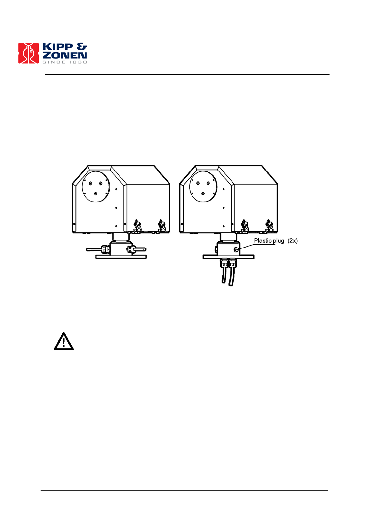
3.2 DATA AND POWER CABLE CONNECTIONS
All 2AP's have a temporary communication and permanent power cable installed at the factory. The
cables are routed through the side of the Azimuth shaft, see figure 3.4 a). An alternative cable
routing through the bottom flange of the 2AP is possible, figure 3.4 b). The Alternate Cable Routing
is advised for a 2AP mounted on a Height Extension Tube, it allows the power and communication
cables to go through the inside of the Stand.
a) b)
Figure 3.4: a) Standard Power and Communication Cable Routing.
b) Alternate Power and Communication Cable Routing.
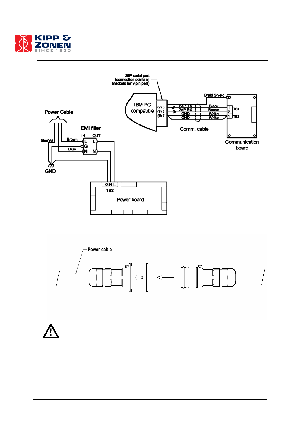
Important: Power and communication cable
The 2AP is supplied with a 3 m power cable with a waterproof in-line connector type “Aqua-safe”.
The connector is in accordance with safety regulations for outdoor usage. The female plug must be
connected to an extension cable that has the proper cable diameter. The voltage drop over the
cable should not cause the supplied voltage to be out of specifications, see chapter 2. To connect
the female plug properly, it is recommended to read the “Aqua-safe” wiring & assembly instruction
that is attached to the cable assembly. The in-line connector provides two sealing caps that should
be fitted to either the male and female plug in case the in-line connector are left unmated in-situ.
This will maintain an ingress protection rating of IP68.
The present connector of the communication cable is not suitable for outdoor usage. It is
recommended to replace the cable by a new one of the proper length.
Note: Once the cable routing has been finalized, be sure to seal the unused threaded holes
(either in the bottom flange or in the azimuth spindle) with the threaded plastic plugs
supplied with the 2AP.
13
Page 15
INSTALLATION AND SETUP
Figure 3.5: Communication and Power Cable Wiring.
Figure 3.6: Power Cable Connector
Important: Circuit breaker
A power on/off switch is not a part of the 2AP, requirements for electrical equipment installed
outdoors specify that:
• A power isolator (switch or circuit-breaker) must be included in the cable installation.
• The isolator must be in close proximity to the equipment and within easy reach of the
operator.
• The isolator must be marked as the power disconnection device for the equipment.
14
Page 16
INSTALLATION AND SETUP
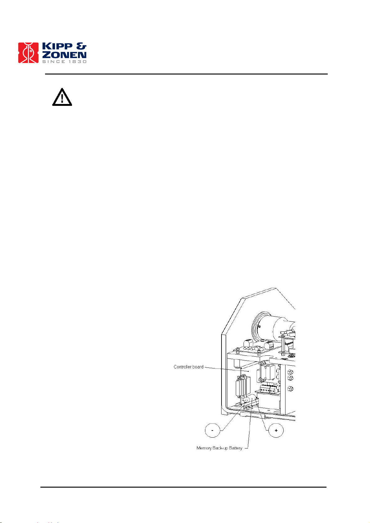
Important: Memory back-up battery
A memory back-up battery is installed on the 2AP controller board. The function of the back-up
battery is to keep the specific 2AP configuration parameters stored in the controller board and to
power the high accuracy internal clock when the 2AP is disconnected from the mains voltage or
during a temporary power cut.
The system does not draw power from the memory back-up battery, when the 2AP is connected to
the power supply.
The battery life time depends on the use of the 2AP. When the 2AP is constantly powered the
battery will function for about 15 years, if the power to the 2AP is turned off the battery life time is
about 6 months.
It is important to have a working back-up battery installed to avoid loss of time and the configuration
settings stored in the 2AP. When the power is turned on again e.g. after a power cut the 2AP will
automatically resume its assigned tasks, as the 2AP can rely on the internal clock time and
configuration settings.
The battery type is Lithium ½ AA, 3.6V, 0.8Ah, non-rechargeable with axial wire terminals soldered
to the controller board. When the battery is ready for replacement the controller board can be taken
out from the 2AP for easy access and re-soldering. Ensure to have downloaded the latest
configuration parameters from the 2AP to the PC before removing the old battery from the controller
board. See section 5.4 on how to download the configuration parameters from the 2AP. Reload the
configuration files when the new back-up battery is installed. The time can be reset by using the
“Set Time” item from the 2AP pull down menu in the Run Suntracker or Run Positioner monitor
window.
Memory Back-up Battery:
- Lithium, ½ AA, 3.6V, 0.8Ah
- With axial wire terminals to be
soldered to the controller board
- Non-rechargeable
- Size: length 23 mm, ∅ 14 mm
Figure 3.6: Location of the Memory Back-up Battery.
15
Page 17

INSTALLATION AND SETUP
3.3 ENVIRONMENTAL CONDITIONS
Important: 2AP cover
Do not operate the 2AP with the cover removed. Doing so can defeat the over-travel sensors which
may result in physical damage to the 2AP and/or any attached equipment. Such damage is not
covered under warranty.
The 2AP cover protects the internal drives and electronics of the 2AP. When the cover of the 2AP is
fitted back onto the unit be sure to reconnect the detachable ground wire to the chassis to maintain
electrical safety and RFI screening. All four latch handles and security screws must be secured.
Proper worm/spur gear mesh is a critical factor in the operation of the 2AP GD. To ensure that the
mesh is in no way affected, it is recommended that the 2AP NOT be operated for extended periods
of time with the main cover removed. This is especially important in any dusty, windy or high
moisture environments. Any debris adhering to the worm and/or spur gear can adversely affect the
operational accuracy of the 2AP and cause premature wear.
A standard 2AP has an operating temperature range of 0°C to +50°C. For remote locations with
harsh temperature conditions, the Cold Weather Cover combined with two (optional) internal
heaters can increase the operating range to -50°C to +50°C, see table 4.
Table 4: 2AP Operating Temperature Range.
To ensure that the 2AP operates without failure due to extreme temperature conditions, it is
recommended that the Cold Weather Cover installation / removal be determined as per the
following:
Below 0°C : Cold Weather Cover must be installed.
0°C to +20°C : 2AP may be operated with Cold Weather Cover installed or removed.
Above +20°C (for more than 8 hours continuously): Cold Weather Cover must be removed to
prevent overheating.
With the 2AP cover installed properly such that all four of the latch handles and security screws are
secured the 2AP is environmentally protected to IP65, according EN 60529: 1991 + CI 1993. This
qualifies the 2AP to be used in weather conditions with all types of precipitation.
Important: Worm / Spur Gear Drive Contamination
Important: Operating Temperature
Standard 2AP
2AP with Cold Weather Cover
2AP with Cold Weather Cover and Heater Kit
2AP with Cold Weather Cover and Extreme Heater Kit
Important: Precipitation
0°C to +50°C
-20°C to +50°C
-50°C to +50°C
-50°C to +50°C (prolonged
exposure and wind-chill)
16
Page 18

INSTALLATION AND SETUP
Important: Altitude restriction
According to the EC guideline (Electrical safety of electric equipment) the 115/230V AC versions of
the 2AP are not aproved for use at altitudes higher than 2000 m. This restriction is related to
clearance (air) and creepage (surface) insulation distances on the power board. Factors such as
humidity, temperature and dry pollution are of great influence.
The 2AP 24 VDC version is not restricted to 2000 m due to the lower voltage.
3.4 SUNTRACKER AND POSITIONER
Attention! Combined Suntracker and Positioner usage of the 2AP Gear Drive
When it is the intention to use the 2AP for both the Suntracker and Positioner purposes it is
recommended to set up the 2AP as a Suntracker. As Suntracker the 2AP must be mounted in a
specific way, with the arrow on the 2AP bottom flange aligned due East. As Positioner, according to
your needs, the 2AP may be mounted in any direction. Setting up the 2AP as Suntracker first will
save having to repeat the set up twice. Read section 4.7 for more information on the possibilities of
the 2AP set up as Positioner.
Important: Information for 2AP Gear Drive users who have used their 2AP for an
extended period of time for Suntracker purposes only and want to
The 2AP is designed for Suntracker purposes. Therefore Win2AP provides all the relevant
information to set up, commission and operate a 2AP as a Suntracker.
With the Win2AP software the 2AP can also be used for Positioner purposes. The 2AP can be
programmed to cycle through a list of targets (positions) determined by the user.
However, some problems might occur when changing over from Suntracker to Positioner operation
with an older 2AP Gear Drive. The problem might occur with older Gear Drive units that have been
running for an extended period of time with limited positioning movement, due to repeated sun
cycling.
Technical explanation: If a 2AP Gear Drive has been used as a Suntracker for an extended
period of time the gears on both the axes become worn in a particular area and deformation of the
worm final gears and the spur primary gears takes place. When changing over to Positioner
operation the 2AP Gear Drive can come to a standstill, because of the transition from the worn part
of the metal gears to the area where the gears have never been used. In the worst case the spur
gears or the nylon gears of the stepper motors will experience the main forces and may get
damaged.
The gear wear as described above produces no effect on the Suntracker accuracy of a 2AP Gear
Drive that is used for Suntracker operation only.
change over to Positioner operation.
17
Page 19

INSTALLATION AND SETUP
4 INSTALLATION AND SETUP
The following sections provide information on the installation of the software and the 2AP setup.
The 2AP has various accessories to enhance and expand its operation, including:
• Tripod Floor Stand
• Height Extension Tube (60 cm)
• Rear Mounting Plate
• Large Side Mounting Plate
• Pointing & Shading Ball Assembly:
Including Large Side Mounting Plates (x2) and a Rear Mounting Plate (x1)
• 2AP Cold Weather Cover
• Ventilation units for Pyranometers/Pyrgeometers
• Sun Sensor
Both the Manual and Win2AP software (see Setup Preparation in the Main Menu) are supplied with
various drawings with technical accessory dimensions that will aid specific 2AP setup demands and
adjustments for alternative mountings.
4.1 WIN2AP SOFTWARE
4.1.1 System Requirements
The minimum computer hardware requirement for the Win2AP software is a 133 MHz Pentium
computer running Windows 95/98/NT/2000/ME, 32 MB of RAM, 200 MB of free hard-disk space,
CD-ROM drive, one free serial port.
For the 2AP installation on site a laptop is needed, with the same minimum system requirements.
Dependent on several conditions, the initial 2AP setup can take up to 1-2 days. Therefore an AC
power supply, or other power backup, for the laptop is necessary.
Tip: It is helpful to use some type of sun shield to shade the laptop during setup of the 2AP.
The intensity of the sun can overheat the computer and/or decrease the readability of the
LCD screen.
4.1.2 Installation
The Win2AP software is supplied on a CD-ROM, a win2ap.ini configuration file is supplied on a
separate floppy disk. The installation of the software is as follows:
• Place the CD-ROM into the PC
• Double click on setup.exe.
• Follow the setup instructions on the screen.
• The configuration file must be installed in the same directory as the Win2AP software.
Tip: Keep the win2ap.ini disk, or a copy of the contents, in a safe place. It will come in handy
when doing a complete re-installation of the instrument.
18
Page 20
INSTALLATION AND SETUP
The Win2AP software is compatible with older 2AP’s that run with DOS software. To upgrade the
software continue with:
• Connect the 2AP communication cable to the PC.
• Double click on Win2AP.exe with the Kipp & Zonen logo to open the software.
• Press the “Troubleshooting” button in the Main Menu.
• Press the “Run CMD” button on the bottom of page 1.
• Select the correct com port.
• To communicate with the 2AP, press the “Connect” button.
• Press the “Read Config From 2AP” button.
• Enter a file name (e.g. Win2AP.ini) to save the configuration file on your PC.
• If the Password reads 65535 it has been set to a default integer. Press the “Disconnect”
button in the CMD window and follow the steps on page 2 of the Troubleshooting Procedure
to reconfigure a Password. You will find the original 2AP password in the baseline.ini file of
the DOS software.
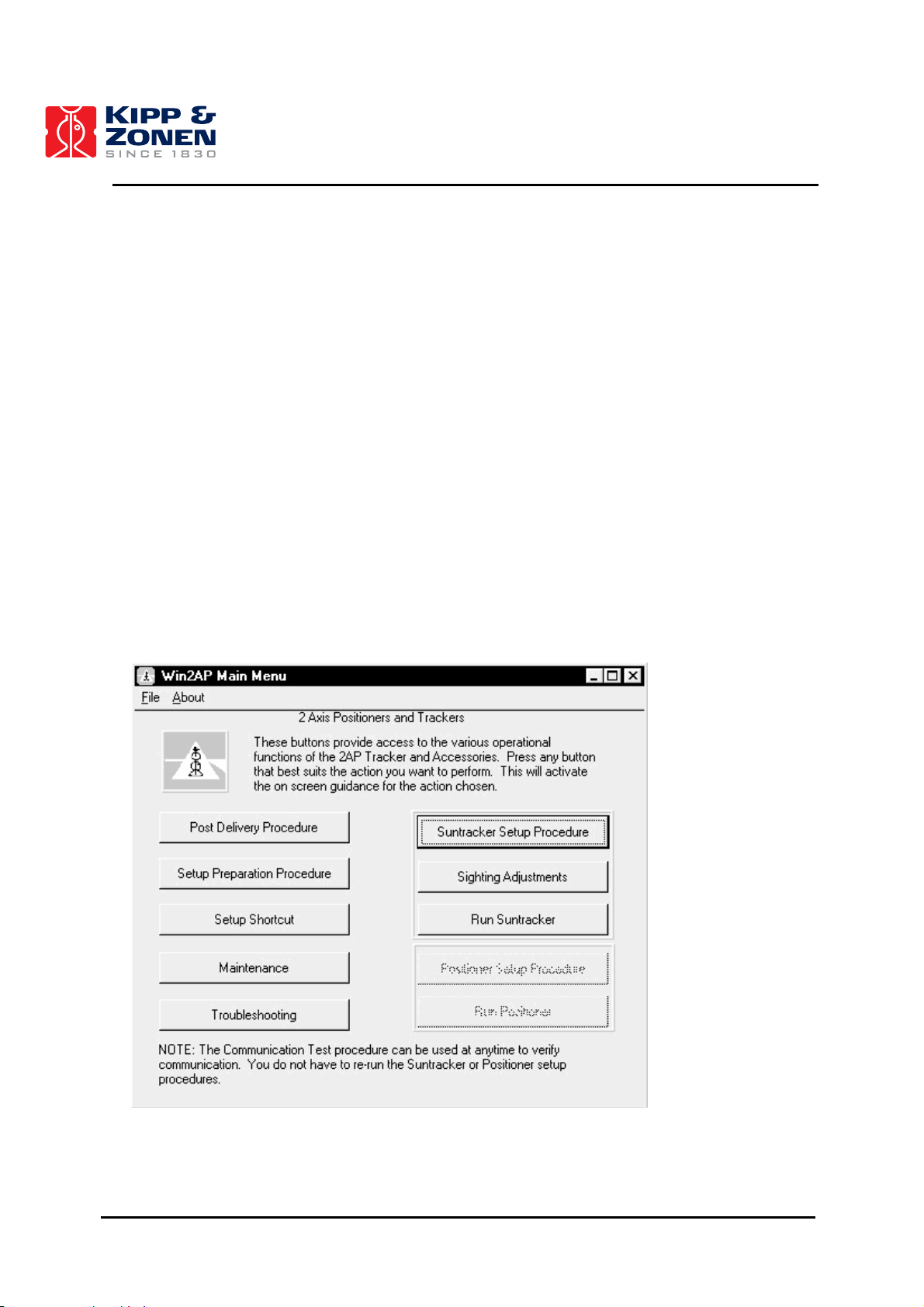
4.1.3 Win2AP Overview
Double clicking on Win2AP.exe with the Kipp & Zonen logo will open the software. The buttons in
the Main Menu of the Win2AP software provide access to the various pages for 2AP instalment, see
figure 4.1. An overview of the various pages behind the buttons in the Main Menu is given in figure
4.2.
Figure 4.1: Win2AP Main Menu.
19
Page 21

INSTALLATION AND SETUP
Post Delivery Check
1. Accessory List
2. Power Use Verification
Setup Preparation
1. Getting Acquainted with the 2AP
2. Communication Test
3. Password Activation / Deactivation
4. Alternate Montage of the 2AP
5. 360º Limit Option (Gear Drive only)
6. Minimum Setup Requisites
Software Setup Procedure
1. Setup Shortcut
Maintenance
1. Maintenance
Troubleshooting
1. Troubleshooting
2. Change Password
3. Cold Start
4. Contact Manufacturer
Suntracker Setup Procedure
1. Mounting Suntracker
2. Power Up Procedure
3. Levelling Gear Drive
4. Rear Mounting Plate Assembly
5. Large Side Mounting Plate Assembly
6. Pointing and Shading Ball Assembly
7. Mounting Sun Sensor
8. Pyrheliometer Installation
9. Pyranometer Installation
10. Verification of Levelling
11. Cold Weather Cover Installation
12. Setting Time and Location
13. Conclusion
Sighting Adjustment
1. Sighting Adjustment without Sun Sensor
Sighting Adjustment
1. Azimuth orientation
2. Sun Sensor Alignment
3. Tilt Correction
4. Active Time Correction
Run Suntracker
1. Suntracker Monitor Window
Positioner Setup Procedure
1. 2AP Azimuth Orientation
2. Mounting the 2AP as Positioner
3. Power Up Procedure
4. Levelling Gear Drive
5. Large Side Mounting Plate Assembly
6. Adapting 2AP Zenith Range
7. Configuring the 2AP for Positioner Purpose
8. Attaching Instruments to the Side Plates
9. Verification of Levelling
10. Cold Weather Cover
11. Conclusion
Run Positioner
1. Positioner Monitor Window
Figure 4.2: Overview of the various pages in Win2AP.
20
Page 22

INSTALLATION AND SETUP
Summarized the normal procedure from the 2AP delivery to the setup at the site is as follows.
Post Delivery Check:
The purpose of going through the Post Delivery Check is two-fold. Primarily it functions as a
delivery check. Appended diagrams will help you become familiar with the 2AP and its optional
accessories.
Secondly, selecting the 2AP purpose and specific accessories will activate the on-screen guidance
for the 2AP setup. Selecting the “Pyrheliometer mounting support for direct solar irradiance
measurements” will provide you with information on how to install Kipp & Zonen radiometers on the
2AP. The selections in the “Post Delivery Check” activate the on screen guidance for your 2AP set
up. See section 4.1.4 for more information on selecting the 2AP purpose.
Setup Preparation Procedure:
The Setup Preparation can be done off-site. This procedure will help you become acquainted with
the 2AP and its optional accessories. Appended diagrams provide the information and technical
accessory dimensions that will help you with specific 2AP setup demands or adjustments.
Suntracker/Positioner Setup Procedure:
After the Setup Preparation you can move on to one of the 2AP Setup Procedures (as selected in
the Post Delivery Check). Follow the on-screen guidance for the 2AP setup at the site. Of course
you can go through the Setup Procedure at anytime. Press the “Connect” button in the Power-up
Procedure to gain access to the information on the accessory set up.
Sighting Adjustment:
If the Suntracker Setup Procedure is completely finished you can start to perform the 2AP Sighting
Adjustments procedure.
Run Suntracker/Positioner:
At this stage, when configured as a Suntracker, the 2AP is ready for unattended operation. The Run
Suntracker monitor window shows you all the 2AP operational parameters.
When used as a positioner, you will come to the main window for Positioner. This window gives you
all the information for target names and the current 2AP position and status.
4.1.4 Selecting the 2AP Purpose
Selecting the right purpose is of great importance for the correct set up of your 2AP. In the “Post
Delivery Check” procedure of the Win2AP software you are able to choose between three options
with respect to 2AP purpose:
1. Suntracking
2. Positioning
3. Suntracking and Positioning
Suntracking:
If the “Suntracking” purpose is selected the “Positioner” part in Win2AP is kept out of site for the
user, which makes section 4.7 of this manual is not applicable. According to the selections in the
“Post Delivery Check” you will be guided through the “Suntracker Setup Procedure” and the correct
“Sighting Adjustment Procedure”.
Positioning:
If the “Positioning” purpose is selected, you chose to not use the 2AP as a Suntracker at all.
Continue by following the instructions of section 4.7, in the Win2AP software you will be guided
through the designated “Positioner Setup Procedure”.
21
Page 23
INSTALLATION AND SETUP
Specify your Positioning needs in the boxes on the first page of the Positioner Setup Procedure.
These selections and the ones in the “Post Delivery Check” will guide you through the installation
procedure of your 2AP.
Suntracking and Positioning:
If the “Suntracking and Positioning” purpose is selected you will be able to interchange between
both purposes by pressing one specific button in the Win2AP “Run Suntracker” or “Run Positioner”
monitor window. As the 2AP is going to be used partly as a Suntracker it is a necessity first to set it
up as a Suntracker. When changing over to Positioner operation the Suntracker configuration
values will remain saved in the 2AP. The 2AP is set to a different operating mode, which allows the
2AP to respond to the Positioner commands. As there are different operating modes (such as sun
tracking, active tracking, active correction, positioning, etc.), when interchanging between the
Suntracker and Positioner the last used operating mode is saved in the win2ap.ini configuration file.
After the 2AP purpose has been determined select in the “Post Delivery Check” each 2AP
accessory that you want to install. Press any button on the right to view a picture of the item. Select
the Pyrheliometer and/or Pyranometer checkboxes for Kipp & Zonen radiometer mounting support
during the 2AP Setup Procedure. All the selections on this page will activate the Win2AP on-screen
guidance. Only the pages corresponding to your selected options will be shown.
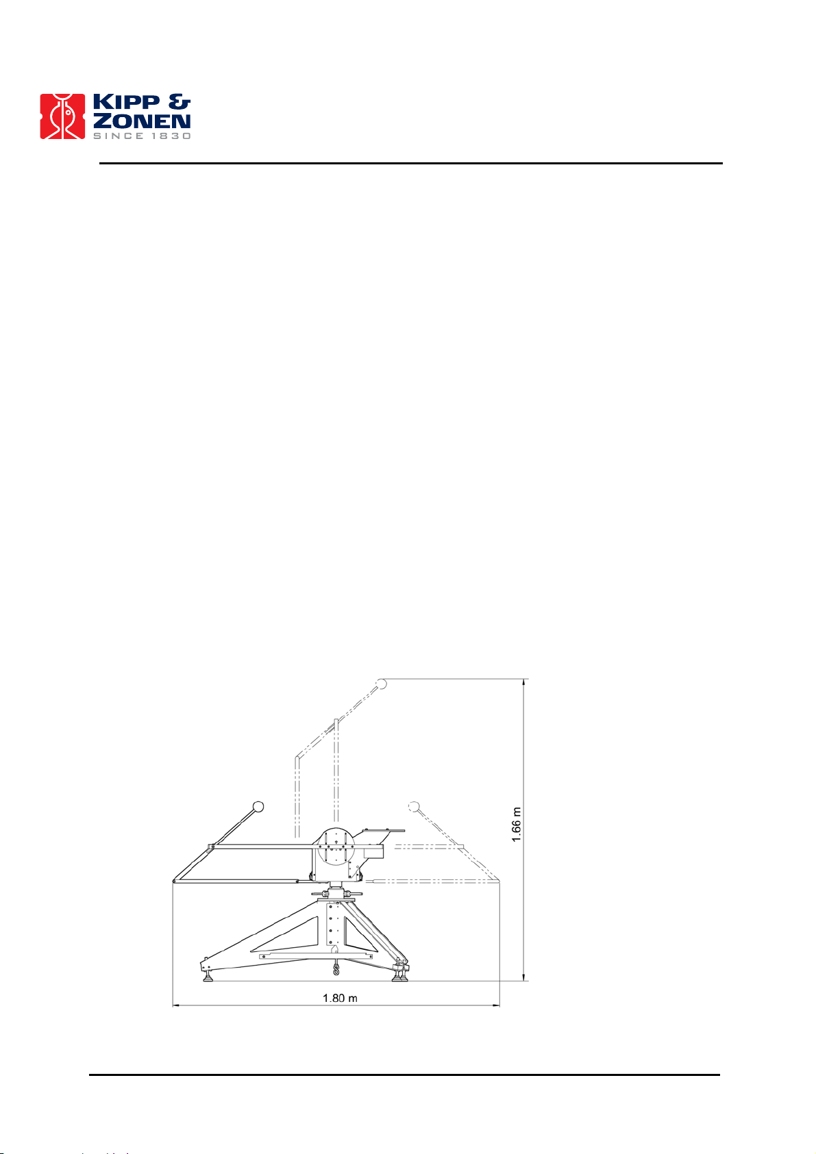
4.2 MINIMUM OPERATING AREA
The 2AP, complete with all the accessories attached, requires a substantial amount of unobstructed
area to operate properly. This should be kept in mind when deciding where and how the unit is
going to be mounted. Figure 4.3 shows the minimum operating areas with respect to both the
Azimuth and Zenith axis of a 2AP complete with all accessories including Tripod Floor Stand and
Pointing & Shading Ball Assembly. See section 4.5.1 for more information on the exact dimensions
of the optional Tripod Floor Stand.
An optional Height Extension Tube (not shown in the diagram below) raises the 2AP by 60 cm.
Figure 4.3: Minimum Operating Area (with Accessories).
22
Page 24

INSTALLATION AND SETUP
Important:
It is important to consider the following points before/during the setup of a 2AP.
• Verify that the Power and Communication cabling is routed properly to prevent cables from
catching on any fasteners or supports.
• Ensure that the surface on which the Suntracker will be mounted is reasonably level, but
above all it is very important to create a very firm base for the feet of the Tripod to sit upon.
• Make sure that the site will be free from any obstructions within the operating circle and
above the horizontal mounting plane.
• Make sure that the 2AP and accessories will be accessible for maintenance purposes.
• Make sure that the 2AP is located in such a way that shadows will not be cast onto the
radiometers at any time.
• Ensure that before operation of the 2AP the Sun Sensor cable and other mounted
instrument cabling will not catch on any fasteners or supports.
• Avoid any possible cable binding or snagging on parts of the 2AP, supports or other
instrumentation.
23
Page 25

INSTALLATION AND SETUP
4.2.1 Installing the 360° Limit Option
A 2AP Gear Drive is delivered with the capability of approximately 540° rotation on the azimuth axis.
For certain installations it may be desirable to limit this rotation. With the installation of a pin in the
over-travel collar, the 540° rotation on the azimuth axis can be limited to approximately 360°.
Note: This rotational limit cannot be utilized if the 2AP is located anywhere within the tropics
(<25° Latitude North or South) as the 540° rotation on the azimuth axis is necessary to
ensure accurate tracking for all periods of the day.
To fit the 360° limit option the Win2AP software must be installed on a computer and
communication with the 2AP must be established. This procedure can be done as a part of the
Setup Preparation off-site.
The 360° limit option is as follows:
• Press the “Setup Preparation” button in the Main Menu of the Win2AP software. The 360°
limit option is given on page 5.
• If the 360° Limit Option is desired select the Terrestrial Hemisphere where the 2AP will be
located. "No function" implies the standard 540° Azimuth rotational configuration.
• For the instalment of the 360° Limit Option, the 2AP must be in the correct position for the
pin instalment. Press the “Position 2AP for pin instalment” button and wait for the 2AP to
stop moving.
• Disconnect the Power Supply.
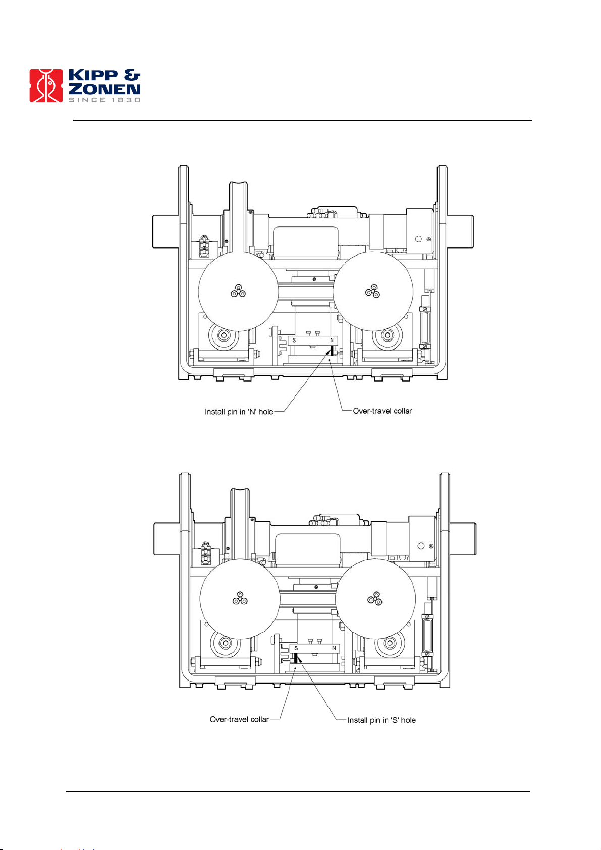
• Remove the 2AP cover. While viewing the unit from the front (see figure 4.4 or 4.5), rotate
the over-travel collar in a clockwise direction (if >25° N) or in a counter-clockwise direction
(if >25° S) until the collar is stopped by the azimuth reference sensor blocker.
• See figure 4.4 or 4.5 on how to install the Limit Pin for North and South of the tropics
respectively. Install the supplied pin (located with the spare fuses) in the appropriate hole in
the over-travel collar. These are identified with an "N" stamped on the outside of the overtravel collar for the Northern Hemisphere and an "S" for the Southern Hemisphere.
• Reconnect the Power Supply.
• Once the pin has been installed and the power reconnected, the software limits must be set
to match the new 360° hardware limits. To do so press the “Set New Limits” button.
Important: When returning to original state of 540° azimuth rotation
If in the future there is a need to return the 2AP to a state where it is capable of 540° Azimuth
rotation, the pin must be removed and the azimuth limits reset to the factory default setting. See the
Setup Preparation procedure in Win2AP Main Menu, page 5, step 11.
• Remove the pin from the over-travel collar.
• Press the “Reset Limits” button .
24
Page 26
INSTALLATION AND SETUP
Figure 4.4: 360° Limit Pin Installation (North of tropics).
Figure 4.5: 360° Limit Pin Installation (South of tropics).
25
Page 27
INSTALLATION AND SETUP
4.3 MOUNTING THE 2AP
Proper placement of the unit is important when installing the 2AP, as it requires a specific amount of
space to operate. Refer to section 4.7 for additional information on how to mount and configure the
2AP as a Positioner instead of as a Suntracker.
The 2AP is supplied with a standard ∅ 203 mm bottom flange, which has a 4-hole (∅ 11 mm)
mounting pattern to match that of the optional Height Extension Tube and Tripod Floor Stand with
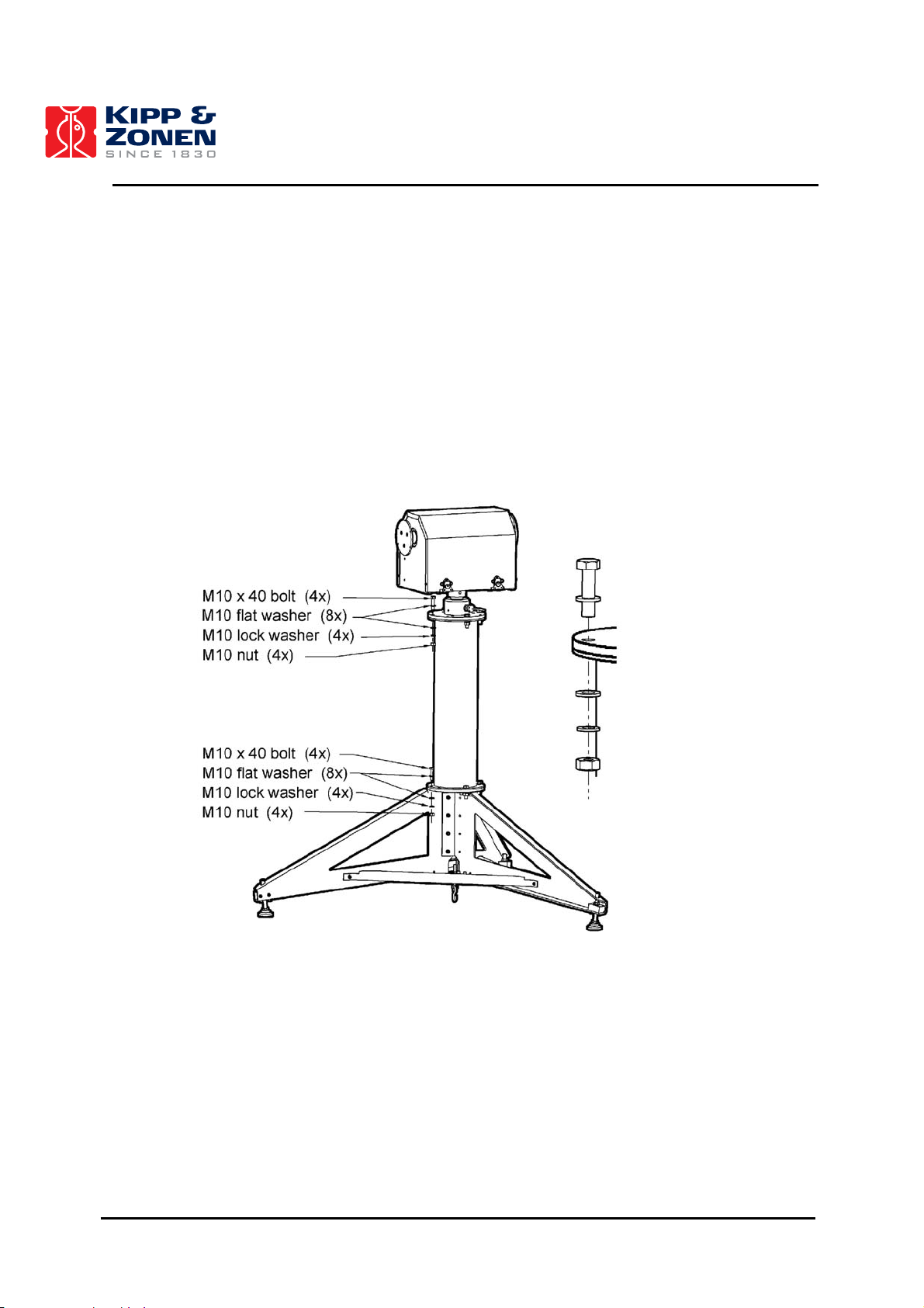
levelling feet. See section 4.5.1 on how to install the optional Tripod.
The Height Extension Tube is an optional accessory. It extends the height of the 2AP by 60 cm.
Without the Height Extension Tube the 2AP can be mounted directly onto the mounting flange of
the Tripod Floor Stand.
Figure 4.6: Mounting the 2AP on the Height Extension Tube and Tripod Floor Stand.
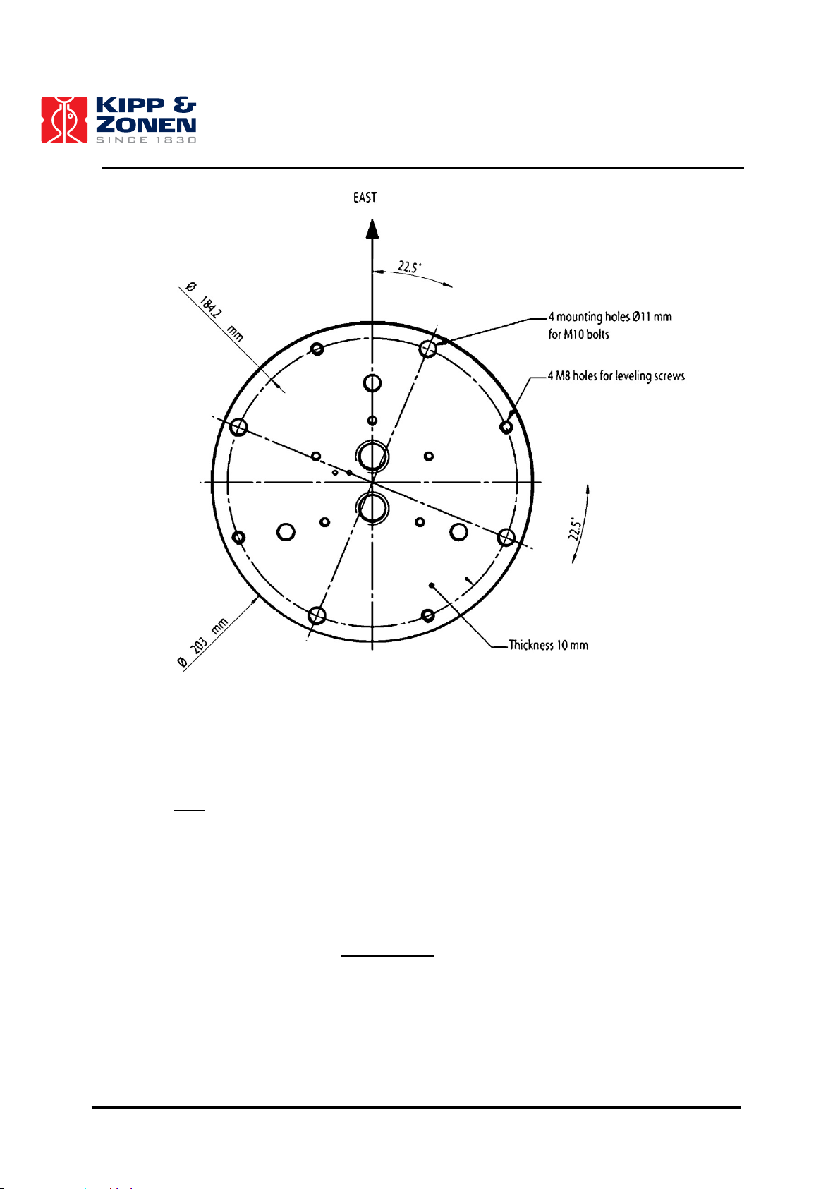
If it is intended to mount the 2AP on a customer-supplied platform, the bottom flange contains an
extra set of 4 holes, which are threaded, and a set of levelling screws. See figure 4.7 for details of
the bottom flange mounting hole pattern and thread type.
26
Page 28
INSTALLATION AND SETUP
Figure 4.7: 2AP Bottom Flange Dimensions.
When the 2AP is set up as a Suntracker the "E" label on the shaft and arrow on the bottom flange of
the 2AP must
be facing geographical East. Preliminary orientation will do at this stage of the Setup.
How to fine-tune the Azimuth orientation of the 2AP will be explained later on, in the Sighting
Adjustment Procedure.
Tip: For now, when installed as a Suntracker an initial Azimuth orientation due East with the
help of a compass will do. In the Home Position the 2AP Zenith axis is perpendicular to
the "E" label on the Azimuth shaft. So with the "E" label pointing due east, the Zenith axis
is pointing North-South.
Note: When the 2AP is used as Positioner only
the 2AP does not necessarily need to be
mounted facing the East. See section 4.7 of this manual for full information about the
different mounting and configuration possibilities for the Positioner purpose.
27
Page 29

INSTALLATION AND SETUP
4.4 LEVELLING THE 2AP
For proper operation the 2AP must be levelled correctly on its stand. The 2AP levelling can be done
either by means of the four supplied levelling screws for mounting on a flat surface or by the three
levelling feet on the optional Tripod Floor Stand.
Prior to configuring the 2AP, it should be levelled on its mounting surface. To help accomplish this
task, the 2AP Gear Drive is equipped with a high accuracy bubble level visible through the viewing
window in the instrument cover.
• The standard bottom flange can function as levelling unit, if the 2AP was purchased without
the optional Tripod Floor Stand. With the main mounting bolts loosened off slightly, adjust
the levelling screws to move the bubble into the center of the level. Once the 2AP is level,
secure the levelling screws in place with the locking nuts and tighten the main mounting
bolts to ensure there will be no movement during operation, see figure 4.8.
• If the 2AP was purchased with the optional Tripod Floor Stand the unit can be leveled using
the three levelling feet on the Stand. Adjust the levelling feet to move the bubble into the
center of the level, see figure 4.9.
Figure 4.8: Levelling 2AP without Tripod.
Bubble level
Viewing window
28
Page 30
INSTALLATION AND SETUP
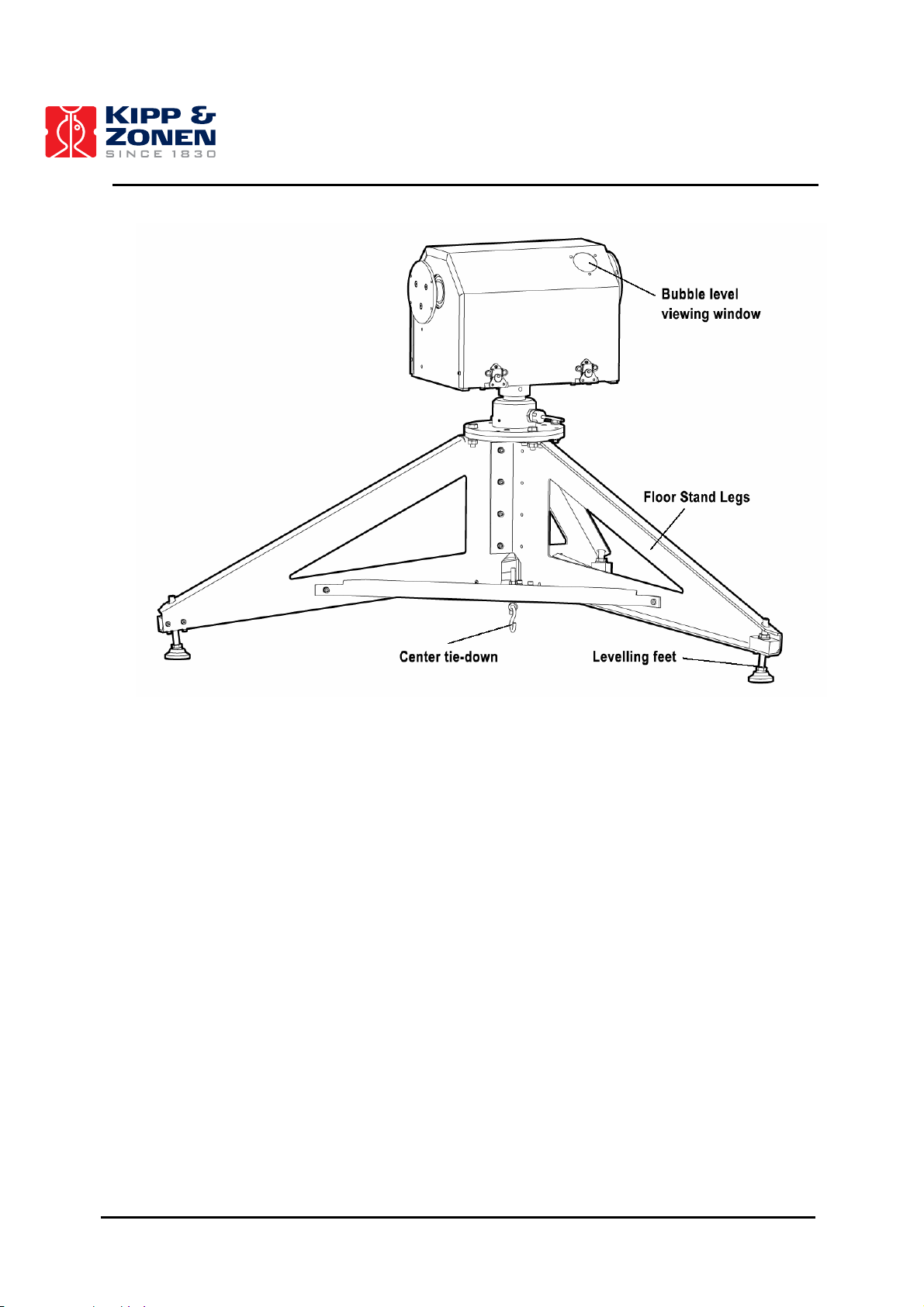
Figure 4.9: Optional Tripod Floor Stand.
4.5 ACCESSORY INSTALLATION
This chapter provides all the information on the accessory installation of a 2AP set up. This
information is also given in the Win2AP software.
4.5.1 Tripod Floor Stand
The Tripod Floor Stand provides a solid and convenient means of mounting the 2AP for all aspects
of operation. Its heavy gauge aluminium construction and hardened paint finish ensure long lasting
durability in all weather conditions. It is equipped with three adjustable feet for easy levelling. Figure
4.11 shows the stand with applicable operating dimensions. Section 4.4 advises on how to level the
2AP properly.
29
Page 31

INSTALLATION AND SETUP
Figure 4.10: Tripod Stand Assembly
Figure 4.11: Tripod Floor Stand Dimensions.
30
Page 32

INSTALLATION AND SETUP
4.5.2 Rear Mounting Plate
Attach the two Upright Side Plates with insulating spacer bars onto the chassis first. You may have
to loosen the side plate screws on one side to get the Top Plate's holes to line up, see figure 4.12.
Do not completely tighten any top plate screws until all the screws have been installed.
Figure 4.12: Attaching Rear Mounting Plate.
31
Page 33

INSTALLATION AND SETUP
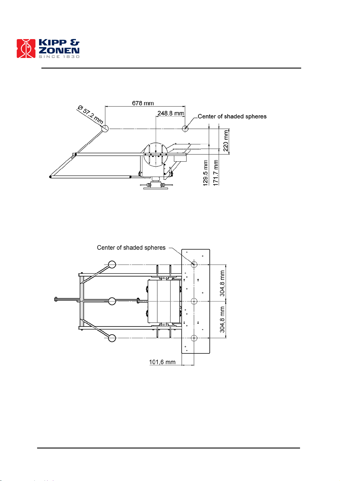
There are two mounting configurations for the Rear Mounting Plate height location, see figure 4.13:
• The higher position, specially designated for ventilated Kipp & Zonen Pyranometers. This
has a height of 129.5 mm with respect to the centres of the shading spheres.
• The lower position, which has a height of 171.7 mm with respect to the centres of the
shading spheres. This allows larger instruments to be mounted.
Figure 4.13: Upright Plate Mounting Patterns.
See figures 4.14 and 4.15 for more information on the height of the Rear Mounting Plate with
respect to the centres of the shading spheres of the Pointing & Shading Ball Assembly.
32
Page 34
INSTALLATION AND SETUP
Figure 4.14: Recommended Instrument Layout (Side View).
Figure 4.15: Recommended Instrument Layout (Top View).
33
Page 35

INSTALLATION AND SETUP
4.5.3 Large Side Mounting Plate
The 2AP is supplied with two standard 127 mm diameter by 6 mm thick instrument Side Mounting
Plates. Each plate is fastened to a split clamp and secured to the Zenith shaft using a cap screw.
Optional are the 203 mm diameter by 6 mm thick Large Side Mounting Plates, which are designed
to be used in conjunction with the Pointing & Shading Ball Assembly. The supplied plates can be
customized to meet your specific configuration requirements. The hole patterns of both the
Standard and the Large Side Mounting Plates are given in figures 4.16 and 4.17.
Figure 4.16: Standard Side Mounting Plate Hole Pattern.
Figure 4.17: Large Side Mounting Plate Hole Pattern.
34
Page 36

INSTALLATION AND SETUP
Prior to mounting the Large Side Mounting Plates, ensure that the 2AP is levelled (according to
section 4.4) and set to the reference position. If the optional Rear Mounting Plate is not installed yet
it is recommended to do this first, as the Large Side Mounting Plates cover the mounting holes of
the Rear Mounting Plate. The Large Side Mounting Plates need to be levelled and aligned properly
to ensure accurate pointing once the 2AP is tracking the sun.
Tip: If a Sun Sensor is to be mounted on one of the Large Side Mounting Plates it will be
easier to mount the special Sun Sensor Clamps with Adjustable Screws first, before
mounting the Large Side Mounting Plate to the zenith shaft, see figure 4.27.
• Level the 2AP according to section 4.4, Levelling The 2AP.
• Before continuing with the assembly of the Large Side Mounting Plate, press the “Home
Position” button in the Suntracker Setup Procedure (page 7 of Win2AP).
• Pre-assemble the Large Side Mounting Plate as shown in figure 4.18 and attach the Side
Plate Assembly to the Zenith shaft. Ensure that the plates are pushed up against the end of
the Zenith shaft.
• Check the circular bubble level once more to verify that the 2AP is still properly leveled.
• As shown in figure 4.19, use a tubular type bubble (spirit) level to level the mounting
clamps. Place the bubble level on the top side clamps. It may be helpful to install one of the
Shading Drive Arms (figure 4.22) to complete this task.
• Tighten the single screw inside the clamp collar to securely clamp it to the shaft.
• Tighten the three screws to securely attach the large side plate to the Clamp Collar.
• Recheck the bubble level on the Side Clamps. If they moved during tightening, slightly
loosen the screws and repeat the process.
Figure 4.18: Pre-assembling Large Side Mounting Plates.
35
Page 37

INSTALLATION AND SETUP
Figure 4.19: Large Side Mounting Plates Levelling.
36
Page 38

INSTALLATION AND SETUP
4.5.4 Pointing and Shading Ball Assembly
The Pointing and Shading Ball Assembly is comprised of several components which, when
assembled to the 2AP, provide a mechanical assembly to ensure accurate shading during normal
solar tracking operations, see figure 4.20.
Figure 4.20: Pointing & Shading Ball Assembly
Section 4.5.6 contains more information on the recommended Rear Mounting Plate layout for the
pyranometers to operate in conjunction with the Shading Balls.
Listed below is a recommended sequence of assembly:
• Install the Lower Pivot Bar on the underside of the chassis bottom plate with designated
screws, see figure 4.21.
• Attach both the Shading Drive Arms with the designated screws. Ensure the counter
weights are facing down. Do not completely tighten the screws yet, some room for installing
the T-bar is required, see figure 4.22.
• Install the T-Bar (without ball rods) as shown in figure 4.23. Install the plastic shoulder
washers onto the threaded studs of the T-Bar. Insert the shoulder washers into the side arm
end holes. Install the outer flat washers and the locking nuts ensuring that all the bushings
are properly seated into the side arms. Only loosely install the locking nuts at this stage.
37
Page 39

INSTALLATION AND SETUP
• Tighten the Side Arm screws. Now tighten the T-Bar locking nuts until most of the clearance
is gone between the arms and shoulder washers. Do not tighten snugly, ensure that the TBar rotates freely but has minimal sideways movement.
• Install the Shading Support Arm to the T-Bar, see figure 4.24. Install the shoulder washers
into the holes as shown. Only tighten the locking nut to minimize clearances, ensure free
rotational movement.
• Install the other end of the Shading Support Arm to the Shading Pivot Bar hole with the
nylon washers and locking nut shown in figure 4.25. Only tighten the locking nut to minimize
clearances, ensure free rotational movement.
• Install the Shading Ball Rods by sliding them into the designated holes. See figure 4.26 for
preliminary positioning of the Ball Rods in the T-Bar. Fine-tuning of the Ball Rods must be
done later in the setup after the Verification of Levelling Procedure. DO NOT OVERTIGHTEN the locking screws, it would make fine-tuning adjustments difficult later in the
procedure.
Note: To verify that the Shading Assembly will not interfere with any obstructions, press the
“Shading Assembly Motion Test” button. This will cycle the Suntracker through a complete
range of motion. Press the “Stop” button at any time to halt the testing motion.
• Mark the “Test Successful” checkbox to complete the Pointing and shading Ball Assembly
procedure.
Figure 4.21: Attaching Pivot Bar
38
Page 40

INSTALLATION AND SETUP
Figure 4.22: Attaching Side Drive Arms
Figure 4.23: Pivot Joint “A” Assembly
39
Page 41

INSTALLATION AND SETUP
Figure 4.24: Pivot Joint “B” Assembly
Figure 4.25: Pivot Joint “C” Assembly
40
Page 42

INSTALLATION AND SETUP
Figure 4.26: Shading Ball Rods Installation
4.5.5 Sun Sensor
The optional Sun Sensor accessory consists of a quadrant sensor fitted within a weather resistant
enclosure with 2AP mounting hard-ware and associated software. A 2AP with Sun Sensor can be
set to three different modes during operation:
1. Suntracking mode:
Normal mode provides operation where the 2AP follows a calculated solar position and logs the
deviation to the measured position. Also the only 2AP suntracking mode if no Sun Sensor is
attached.
2. Active mode:
When the sun is present this mode provides operation where the 2AP follows a measured solar
position and logs the deviation to the calculated position.
3. Correcting Time:
When the sun is present this mode provides operation where the 2AP follows a measured solar
position and logs the deviation to the calculated position. This mode enables the 2AP to correct
for any possible clock drift of the controller board.
41
Page 43

INSTALLATION AND SETUP
4.5.5.1 Sun Sensor Installation
The installation of the Sun Sensor is as follows:
• Remove two of the standard Pyrheliometer Clamps on a Large Side Mounting Plate.
• Instead attach the Adjustable Mounting Clamps supplied with the Sun Sensor Kit to the
Side Plate with the designated screws in the same manner as the Pyrheliometer Clamps,
see figure 4.27.
Figure 4.27: Attaching Sun Sensor with Adjustable Clamps.
Tip: It is recommended to change the Adjustable Mounting Clamps for the Sun Sensor before
going to the 2AP installation site. The standard clamps on the Large Side Mounting Plate
might be difficult to remove on-site.
Important:
Turn off the supply power to the 2AP before proceeding.
• Install the Extension Springs (x2) with the designated screws and washers. Do not tighten
the screws yet, leave some space.
• Ensure that the four Aluminium Adjusting Screws are not protruding past the inside surface
of the clamp. This will allow the Sun Sensor to mate up with the Base Clamp under the
Spring.
• Slide the Sun Sensor through the clamps and the springs. Ensure that the Sun Sensor is
mounted so that it’s decal is on top (facing upwards) and the protuding screw on the Sun
Sensor is facing down. The protruding screw is on the bottom of the Sun Sensor (not visible
in the diagram).
42
Page 44

INSTALLATION AND SETUP
• Ensure the Adjusting Screws are not touching the Sun Sensor body yet, this will be good
enough for a rough initial alignment.
• Tighten the screws which hold the springs.
• Pass the ground terminal and connector leads through the strain relief bushing, see figure
4.28.
Note: If the Strain Relief Bushing (Cable Gland) was not already installed at the factory, you will
have to install the supplied bushing into the underside of the chassis bottom plate.
Remove the plastic plug and then apply thread sealant/lubricant to the bushing threads.
Tighten the bushing into the plate snugly. Take care to not over-tighten the bushing;
removal in the future could be difficult.
Figure 4.28: Routing Sun Sensor Cable
• Once the cable has been routed as shown and secured in the Strain Relief Bushing, the
electrical connections can be made. Connect the Sun Sensor ground wire (ring-tongue
terminal) to the chassis, see figure 4.28.
• Clamp the ferrite core around the cable, as shown in the diagram above
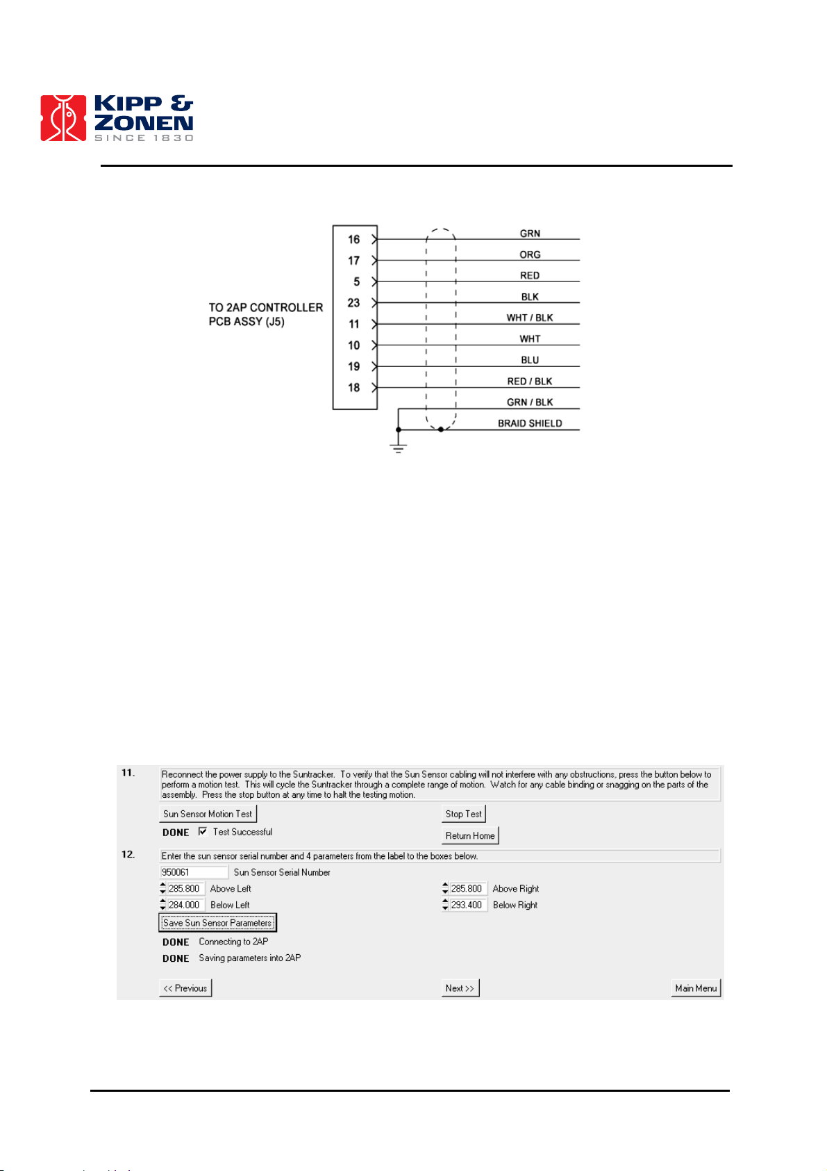
• Insert the connector pins from the end of the Sun Sensor cable into the j5 connector of the
wiring harness as per schematic, see figure 4.29.
• Turn on the supply power to the 2AP after the Sun Sensor cable has been connected.
• Press the “Sun Sensor Motion Test” button, this will cycle the Suntracker through a
complete range of motion. Watch for any possible cable binding or snagging.
43
Page 45
INSTALLATION AND SETUP
Figure 4.29: Sun Sensor Wire Connections.
Tip: It may be helpful to temporarily disconnect the connector from the PC board to install the
pins. A pin insertion & extraction tool is included to aid in this step (or removal, if required).
4.5.5.2 Setting Sun Sensor Parameters
The Sun Sensor is provided with a four-quadrant photodiode. Each quadrant has its own calibration
factor. To access the relevant page to set the Sun Sensor parameters, the optional Sun Sensor
needs to be selected in the “Post Delivery Check” in the Win2AP software. Selecting it will make
page 7 of the “Suntracker Setup Procedure” become accessible. Enter the Sun Sensor serial
number and the four calibration parameters in the designated boxes, see figure 4.30. Pressing the
“Save Sun Sensor Parameters” button will save the parameters into the 2AP.
Figure 4.30: Setting Sun Sensor Parameters
44
Page 46

INSTALLATION AND SETUP
4.5.6 Attaching Instruments to the 2AP
This section describes how to attach Kipp & Zonen radiometers for diffuse and direct solar
measurements. Section 4.5.6.3 provides additional information on the installation of other than
Kipp & Zonen instruments.
The 2AP is specially designed for direct and diffuse sunlight measurement applications. The
Shading Assembly provides mounting for three shaded pyranometers (diffuse radiation). Two Large
Side Mounting Plates provide mounting for 4 pyrheliometers, or 3 pyrheliometers and 1 Sun Sensor.
4.5.6.1 Attaching Kipp & Zonen Radiometers to the Large Side Mounting Plates
Figure 4.31 shows how to install Kipp & Zonen Pyrheliometers on the Large Side Mounting Plates.
See the Kipp & Zonen CH 1 Pyrheliometer and the datalogger installation manuals for more
information.
Figure 4.31: Pyrheliometer Installation Diagram.
Important: Mount the Pyrheliometer in the clamps far away enough from the Rear Mounting
Plate, such that the rear visor plate cannot hit the plate.
4.5.6.2 Attaching Kipp & Zonen Radiometers to the Rear Mounting Plate
A 2AP with Pointing & Shading Ball Assembly provides the ability to measure diffuse light irradiance
with up to three pyranometers/pyrgeometers. The 2AP Pointing and Shading Assembly is designed
for Kipp & Zonen radiometers fitted with the CV2 Ventilation System. Adapters for raising the
radiometers must be used to fill in the space when CV2 ventilation units are not used.
Figure 4.32 shows an example of how to install a Kipp & Zonen Pyranometer with CV 2 Ventilation
Unit on the Rear Mounting Plate. Figure 4.33 shows how to install a Kipp & Zonen Pyranometer
with adapter on the Rear Mounting Plate. Ensure that the radiometers are securely retained on the
Rear Mounting Plate. At a later stage, after verification of levelling of the 2AP, fine-tuning of the
radiometers will be required. See the Kipp & Zonen Pyranometer/Pyrgeometer instruction manual
for more information.
45
Page 47

INSTALLATION AND SETUP
Figure 4.32: Kipp & Zonen Pyranometer with CV 2 Installation Diagram.
Figure 4.33: Kipp & Zonen Pyranometer with Adapter Installation Diagram.
46
Page 48

INSTALLATION AND SETUP
The Win2AP Pyranometer Installation page is provided with a button to perform a motion test (page
9 of the Suntracker Setup Procedure). This allows verification that the installed instrumentation and
cabling will not interfere with any obstructions around the Suntracker Assembly. The Motion Test
procedure will cycle the Suntracker through a complete range of motion. Watch for any cable
binding or snagging. Press the stop button at any time to halt the testing motion.
Additional CV2 information:
The CV2 Ventilation Unit is designed for ventilating Kipp & Zonen solar radiation sensors
(pyranometers and pyrgeometers) and can be used outdoors under all weather conditions. The CV2
is available with or without a heater, see table 5. The reliability and accuracy of solar radiation
measurements are improved significantly by using this controlled heated airflow over the
radiometer. The main advantages of ventilating are:
1. No precipitation of morning dew, which otherwise would disturb the measurement.
2. No deposition of hoarfrost, which otherwise would disturb the measurement (heater
necessary).
3. Less infrared offset, due to infrared radiation exchange between the sensor element and
the glass dome under calm clear sky conditions.
Table 5: CV 2 Specifications.
Ventilation power
5 Watt continuous
Heating (optional) 5 Watt and 10 Watt
Operating temperature -30ºC to +70ºC
Air temperature rise caused by CV 2
< 0.25 K @ 0 Watt (blower only)
< 0.5 K @ 5 Watt (heater)
< 1 K @ 10 Watt (heater)
Offset caused by heater < 1 W/m2 using pyranometer CM11
Cable length 10 m
Power required 12 Volt DC, 1.25 A (with heater)
47
Page 49

4. INSTALLATION AND SETUP
INSTALLATION AND SETUP
4.5.6.3 Installation of other than Kipp & Zonen Instruments
The Manual and Win2AP software include diagrams that can be used to customize the accessories
to fit instruments other than those manufactured by Kipp & Zonen. This section also allows for the
mounting of equipment such as cameras when the 2AP is used as a Positioner.
Information: Points of consideration
Rear Mounting Plate:
Mounted in the lower position the Rear Mounting Plate can be used to gain height for instalment of
taller instruments. It might be necessary to customize special adapters to align with the centres of
the shaded spheres of the Pointing & Shading Ball Assembly. In combination with the Pointing &
Shading Ball Assembly the Rear Mounting Plate must not be mounted any lower than the
designated lower mounting hole pattern of the Upright Plates. This is to avoid the Shading Drive
Arms hitting the Rear Mounting Plate. See figure 4.14 and 4.15 for more information regarding the
dimensions of the centres of the shaded spheres.
Large Side Mounting Plates on the Gear Drive:
The Gear Drive is the heavy-duty version of the 2AP and can handle Side Plate payloads up to 65
kg, counter weights included. The Gear Drive also maintains its torque (and therefore its position)
when the power is turned off.
4.5.7 Cold Weather Cover
A standard 2AP has an operating temperature range of 0°C to +50°C. For remote locations with
harsh temperature conditions, the Cold Weather Cover combined with two (optional) 50W –
115/230V internal heaters can increase the operating range to -50°C to +50°C, see table 6.
Table 6: 2AP Operating Temperature Range.
Standard 2AP
2AP with Cold Weather Cover
2AP with Cold Weather Cover and Heater Kit
2AP with Cold Weather Cover and Extreme
Heater Kit
0°C to +50°C
-20°C to +50°C
-50°C to +50°C
-50°C to +50°C (prolonged exposure and
severe wind-chill)
The Cold Weather Cover is made of a durable nylon shell filled with insulation and provides
excellent protection in all weather conditions. The cover installs easily by slipping over the main
body of the 2AP and is equipped with convenient fastening flaps for quick and simple installation.
The 2AP Cold Weather Cover is designed to fit both the standard 2AP and a unit fitted with all
accessories. For a standard 2AP with no Shading Arms or Rear Mounting Plate, installation of the
cover is possible from both sides of the unit. For a 2AP fitted with the Shading Arms and Rear
Mounting Plate the cover must be installed from the Shading Arm side, allowing the Rear Upright
Mounting Plates to pass through the open seams on both sides.
The optional internal heaters must be factory-installed prior to delivery. The Extreme Heater Kit is
strongly recommended for harsh climates, such as Polar regions. Extra heating elements will
protect the 2AP against the extreme continuous cold and severe wind-chill and the extra torque of
the GD is capable of breaking ice that may form around the shafts of the 2AP.
48
Page 50

INSTALLATION AND SETUP
4.6 COMMISSIONING 2AP AS SUNTRACKER
The procedures described in this section are essential to insure good performance during operation.
Commissioning a 2AP covers the configuration with the Win2AP software. This includes setting the
time, setting the location parameters and performance of the final Sighting Adjustments.
4.6.1 Setting the Time
This step configures the 2AP to Greenwich Mean Time (GMT), which is required by the suntracking
algorithm in the firmware. When the command is given, the Win2AP gets the time from the PC
connected to the 2AP. Ensure that you have an accurate time reference at the 2AP installation site.
Greenwich Mean Time or Coordinated Universal Time is the standard time at longitude = 0
longitude line which goes through Greenwich, England), which is used as a standard around the
world to assist in synchronizing data collection.
There are two options:
1. The PC time can be set to local time,Win2AP will take the local time zone automatically into
account and calculate the GMT.
2. If the 2AP site is in a remote place the time and time zone can be difficult to determine.
Setting the PC time and time zone directly to Greenwich Mean Time will fix the time zone
problem.
Note: To calculate GMT Win2AP relies on the Daylight Saving Time of Windows. Although it is
possible to use the local time option, be aware that this procedure is not perfect. When
using the local time option, ensure GMT is set correctly at the moment of the 2AP set up.
The only way around this is to set the time and time zone directly to GMT.
Set the PC time as follows:
• Click on the Start button on the windows Taskbar.
• Click on Control Panel under Settings.
• Double click on the Date/Time icon.
• Set the time according to your accurate time reference.
• Go to the “time zone” tab and select the appropriate time zone.
Set the 2AP time as follows:
• With the 2AP power on and communications connected to the correct serial port, start the
Win2AP program.
• Go to the “Setting Time and Location” page in the Suntracker Setup Procedure .
• Press the “Get 2AP Time” button.
• In the text box on the right the time difference between the PC and the 2AP is shown.
• The difference in time must not be more than 10 seconds.
• Press the “Set 2AP Time” button to adjust the 2AP time to the PC time.
º (the
49
Page 51

INSTALLATION AND SETUP
Figure 4.34: Setting Time, Location, Mean Local Pressure and Start Suntracking.
Main Menu, Suntracker Setup Procedure, page 12.
Note: When the time has been set directly to GMT ensure that the Time Zone is set to
Greenwich Mean Time as well.
4.6.2 Setting the Location
The 2AP requires the correct local geographical coordinates (Latitude, Longitude) and mean local
pressure to accurately track the sun, see figure 4.34. The mean local pressure is mainly dependent
on the altitude of the 2AP’s set up location.
• Enter the Latitude and Longitude in the designated boxes in decimal numbers (at least
three decimal places). Use the “North/South” and “East/West” buttons on the right to
confirm the positive or negative terrestrial Hemispheres.
• Enter the mean local pressure at the site. If the mean pressure is unknown, enter the
altitude for the site (above sea level) and press the “Calculate Pressure” button. The correct
pressure will appear in the Mean Local Pressure text box.
• Press the “Set Location” button to save the instrument location into the 2AP.
50
Page 52

INSTALLATION AND SETUP
4.6.3 Start Suntracking
The time, location and pressure parameters are the necessary variables for the 2AP to calculate the
sun’s position in the sky, see figure 4.34. It is important that these variables have been entered
correctly and that the 2AP has been levelled properly. A final manual Azimuth correction can be
done during the Sighting Adjustment procedure later on.
Press the "Start Sun Tracking" button to set the 2AP function to "Sun Tracking". The "Following
Sun" indicator will light up green when this process successfully finishes (it will take a couple of
minutes to complete). Refer to the Troubleshooting procedure if "Start Sun Tracking" fails.
Now that all the accessories are installed and the 2AP is accurately levelled and located, one can
move on to the Sighting Adjustment procedure. The Sighting Adjustment procedures with and
without the optional Sun Sensor are different. Due to the selection of the optional Sun Sensor in the
“Post Delivery Check” the right procedure (with or without Sun Sensor) will be launched in the
software when pressing the “Sighting Adjustments” button.
4.6.4 Sighting Adjustment without Sun Sensor
This section applies only if you have not purchased the optional Sun Sensor.
The Sighting Adjustment will compensate for errors in the initial position of the 2AP. If, in the Home
Position, the 2AP is not pointing exactly to the East (Azimuth orientation) the Sighting Adjustment
will correct for this. This is a fixed offset. Hence it will correct for levelling inaccuracies of the (Large)
Side Mounting Plates. With the 2AP operating in Suntracking mode the sun can be used as a
pointing reference to visualise any positioning errors.
Notes: During the “Sighting Adjustment without Sun Sensor” procedure continuous sunlight is
required.
The Sighting Adjustment procedure will not compensate for a pointing error due to
levelling inaccuracies of the 2AP.
• Run the Sighting Adjustment procedure from the Main Menu of the Win2AP software.
• If the current 2AP mode shown in the text box at step 1 is not "Suntracking", select this
mode from the right.
• Go to, and finish the “Setting Time and Location” page of the Suntracker Setup Procedure if
the 2AP remains idle.
• Use one of the "Sighting Targets" of the Large Side Mounting Plate Clamps (or even better,
the "Manual Sighting Target" if an optional CH 1 Pyrheliometer is installed). The sun will
project a bright dot onto the Rear Clamp Target. If the Light Dot is not on the Target Hole,
do the following.
• If you have purchased the optional Tripod slightly lift the complete Tracker and turn it to
correct for an Azimuth error (if possible).
• Re-level the 2AP if you moved the 2AP and Tripod, to correct for the azimuth orientation.
• Step 6 of the Sighting Adjustment page can be used to correct for a possible final Azimuth
error and levelling inaccuracies of the Large Side Mounting Plates with the software. If the
Light Dot is close to, but not within the Target Hole, then an initial manual sighting will be
required. The entered corrections are interpreted as an offset.
51
Page 53

INSTALLATION AND SETUP
• It is recommended to start with the Azimuth Adjustment first (before performing any Zenith
adjustments consult the Note below). To do this, install Azimuth correction numbers (in
degrees) into the designated boxes (max. 4º at the time). Press the "Correct" button to
adjust the tracker, and wait until the "following sun" indicator is green. Repeat this step until
you have corrected for the Azimuth error.
- Azimuth Correction: Enter positive correction if 2AP is counter-clockwise (when
viewed from above), or negative correction when clockwise, from the desired position;
- Zenith Correction: Enter positive correction if 2AP is pointing above, or negative
when pointing below, the desired position.
Note: Theoretically, after correcting for the final Azimuth error, the Suntracker should be able to
follow the sun within a 0.1 degree error. However, small position, time, pressure and
levelling inaccuracies might be the reason for a remaining zenith error. Look at your
sighting target (after correcting for any Azimuth error) to get an impression of the Zenith
error due to these errors.
• Recheck the following points if necessary before adjusting for any zenith error:
1. Check if the 2AP itself is leveled properly (section 4.4).
2. Check if the time, time zone and location are set correctly (sections 4.6.1 and 4.6.2)
3. Check if the Side Plates are leveled properly (section 4.5.3)
Tip: If you are sure that the remaining Zenith error is due to levelling inaccuracies of the Large
Side Mounting Plate in the Home position (by excluding the time, location, pressure
parameters and 2AP levelling), you can unscrew the Side Plates, one by one, during
Suntracking and adjust for the Zenith error.
• Press the "Save CFG" button to save a back up copy of the ini file.
• You have now finished the complete 2AP setup if you have levelled the 2AP as accurately
as possible and minimised the possible errors as mentioned in this section. You may
disconnect your computer from the 2AP or go to the Main Menu and press the "Run
Suntracker" button to view the Suntracker monitor window.
• For optimal performance of the 2AP it is advised to use Win2AP every one or two months to
correct the time, within 10 seconds. See chapter 2 for the specifications on the real time
clock on the 2AP controller board.
Tip: At this time fine adjust the Shading Ball Rods (of the optional Pointing & Shading Ball
Assembly) such that the Balls cast shadows onto the centres of the sensing elements of
the pyranometers on the Rear Mounting Plate.
4.6.5 Sighting Adjustment with Sun Sensor
This section applies only if you have purchased the optional Sun Sensor to operate in conjunction
with the 2AP.
Due to the selection of the optional Sun Sensor in the “Post Delivery Check” of the software the
right procedure will be launched when pressing the “Sighting Adjustment” button in the Main Menu
of the Win2AP software.
During the 2AP setup the Sighting Adjustment with Sun Sensor procedure will compensate for all
errors in the initial position, for overall assembly error and minor levelling inaccuracies of the 2AP
and Side (Zenith) Plates. The Sighting Adjustment with Sun Sensor will correct for this. The
accuracy of the Sun Sensor is higher then the mechanical accuracy of the 2AP, therefore the Sun
Sensor is supplied with special clamps with adjusting screws to align the Sensor with other
52
Page 54

INSTALLATION AND SETUP
instruments mounted on the 2AP. With the 2AP operating in Suntracking mode (normal mode) the
sun can be used as a pointing reference. An activated Sun Sensor will overrule the Suntracker
algorithm therefore it needs to be aligned with the other installed radiometers.
During operation the usage of the optional Sun Sensor allows active tracking to correct for minor
pointing drifts due to seasonal temperature changes, internal clock drift, etc. This mode provides
optimal unattended operating performance of the 2AP.
Carry out the following procedures to optimise the operating performance of your 2AP.
4.6.5.1 2AP Azimuth Orientation
This section will correct the 2AP for an excessive Azimuth orientation error. Hence it can give you a
visual interpretation of any remaining 2AP setup positioning errors, due to minor inaccuracies in
location, time, mounting the zenith plates and 2AP levelling.
Fine-tuning the Azimuth orientation can be done with the help of the Sun Sensor in the next section.
• If the current 2AP mode shown in the text box at step 1 is not "Suntracking", select this
mode from the right.
• Use one of the "Sighting Targets" of the Large Side Mounting Plate Clamps (or even better,
the "Manual Sighting Target" if an optional CH 1 Pyrheliometer is installed). The sun will
project a bright dot onto the Rear Clamp Target. If the Light Dot is not on the Target Hole,
do the following.
• If you have purchased the optional Tripod slightly lift the complete Tracker and turn it to
correct for an Azimuth error (if possible).
• Re-level the 2AP, if you moved the 2AP and Tripod, to correct for the azimuth orientation.
Step 6 on page 1 of the Sighting Adjustment Procedure of Win2AP can be used to correct for a
possible excessive final Azimuth error by using the software. This step can also be used if the 2AP
stand is fixed. The entered corrections are interpreted as an offset.
Note: The procedure in the next section (4.6.5.2) will correct for a final Azimuth correction
automatically. You may skip the remaining steps of this section if you can already see that
your pointing reference has only a small Zenith error (within 1°).
• Step 6 of the Sighting Adjustment will correct for a possible Azimuth orientation error. The
entered corrections are interpreted as an offset. To do this, install decimal Azimuth
correction numbers into the designated text box. Press the "Correct" button to adjust the
tracker, and wait until the "following sun" indicator is green. Repeat this step until you have
corrected for any Azimuth error (max. 4º at the time).
Azimuth Correction: Enter positive correction if 2AP is counter-clockwise, or negative
correction when clockwise, from the desired position when viewed from above.
Theoretically, after correcting for the final Azimuth error the Suntracker should be able to follow the
sun within a 0.1 degree error. However, small position, time, pressure and levelling inaccuracies
might be the reason for a remaining zenith error. Look at your sighting target to get an impression of
the Zenith error due to these errors.
A significant error in the time or position parameters leads to both a Zenith and Azimuth error.
Recheck the time and location parameters if necessary to adjust for any excessive zenith error, see
sections 4.6.1 and 4.6.2. Repeat this section if you have found an excessive time and/or location
error. Move on to the next section if you have observed only a minor Zenith error.
53
Page 55

INSTALLATION AND SETUP
4.6.5.2 Sun Sensor Alignment
This part of the Suntracker installation will aid alignment of the Sun Sensor with radiometers
mounted on the 2AP. For the Sun Sensor Alignment procedure press the Sighting Adjustment
button in the Main Menu and go to page 2.
Notes: During the “Sun Sensor Alignment” procedure continuous direct sunlight is required to
avoid errors.
Before continuing, ensure that the Alignment Adjusting Screws are not touching the Sun
Sensor Body yet; this will be good enough for a rough initial alignment.
• Press the “Set Sun Sensor for Alignment Process” button to select the sun sensor manual
sighting procedure. Pressing this button will set the 2AP to Active Tracking. This means
that the Tracker will adjust automatically after finishing each observation. This button also
decreases the Sun Sensor’s usual observation time interval from 600 seconds to 10
seconds, which allows a quicker response during the Sun Sensor alignment process. Wait
until the "following the Sun" indicator is lit.
• When the Sun Sensor is following the sun it will adjust for minor inaccuracies every 10
seconds. Ensure the Alignment Adjusting Screws are not touching the Sun Sensor Body
yet; this will be good enough for a rough initial alignment.
• Choose a sighting target on the Side Plate with the Sun Sensor fitted. Use one of the
"Sighting Targets" of the Large Side Mounting Plate Clamps (or even better, the "Manual
Sighting Target" of an optional CH 1 Pyrheliometer). The sun will project a bright dot onto
the Rear Clamp Target.
• Adjust the screws on the Sun Sensor Clamps until the dot is exactly on the target. One
rotation of an adjusting screw results in approximately 0.30º change. Allow a minimum of 20
seconds after each adjustment (two observations) for the 2AP to re-align.
• Once the mounted instruments are appropriately aligned, press the "Set 2AP for Automatic
Fine Adjustment" button. Wait until the "getting sun sensor data" indicator is green,
approximately 2 minutes after following the sun begins.
This button sets the 2AP to Suntracking (normal) mode and resets the Sun Sensor’s
observation time interval to the usual 600 seconds (10 min.) for operational purposes.
• Pressing the "Calculate" button will use the Sun Sensor data to automatically compute the
remaining Azimuth and Zenith correction values. You may press more than once to get a
desired correction value. Press the "Accept" button, wait until the "getting sun sensor data"
indicator is green (this will take a few minutes). Then press the "Calculate" button again.
The correction values should get smaller and it is recommended to repeat this step until the
auto correction values become less than 0.1 degree.
Tip: Now that the Large Side Mounting Plate with Sun Sensor is aligned an error due to
mounting (levelling) of the other Side Plate might have become apparent. Loosen the 3
side screws and the Clamp Collar screw in the other Side Plate and align it with the Sun
Sensor Side Plate.
Tip: At this time fine adjust the Shading Ball Rods (of the optional Pointing & Shading Ball
Assembly) such that the Balls cast shadows onto the centres of the sensing elements of
the pyranometers on the Rear Mounting Plate.
• At this point the Sun Sensor should be aligned with all the radiometers mounted on the
2AP.
• Move on to the next section to prepare the 2AP Tilt Adjustment.
54
Page 56

INSTALLATION AND SETUP
4.6.5.3 Tilt Adjustment
The previous two sections describe how to fine-tune the 2AP, by correcting for errors in the initial
position of the 2AP, for overall assembly error, and how to align the Sun Sensor with the installed
radiometers. However, this is a momentary adjustment. Due to minor 2AP levelling inaccuracies the
path the 2AP follows will deviate from the path of the sun. This error will vary with the time of day.
The procedure in this section will compensate for a minor error in levelling only. Performing a Tilt
Correction requires several days of sun sensor observation data to be collected. When acquiring
observation data for the Tilt Adjustment the 2AP must be running in Active Tracking mode.
Note: To gather data for the Tilt Correction, Correcting Time mode must be disabled.
After the 2AP has gathered enough Sun Sensor observations reconnect the PC to the 2AP to
retrieve the data for processing. To correct for a minor error in levelling, the Tilt Adjustment applies
an offset to the Azimuth, Zenith, Longitude and Latitude values.
For the Tilt Adjustment procedure press the “Sighting Adjustment” button in the Main Menu and go
to page 3.
• To collect tilt analysis data, the Suntracker should be running in Active Tracking mode. If
the current mode shown in the box below is not "Active Tracking", select this mode from
the list on the right.
• Please consider ALL of the following points when you collect data for the tilt correction
analysis:
- Divide daytime into 10 equal time periods.
- Each time period should be at least 1 hour long.
- For each period, there must be observations during four separate days.
- Each observation requires 10 minutes of continuous sunlight.
- The time must be set accurately for the data collection period (within 10 seconds).
• You may finish this procedure now and go to the Suntracker monitor window. Go to the
Main Menu and press the “Run Suntracker” button. Allow the 2AP to collect tilt analysis
data for four sunny days, then return to the “Tilt Correction” procedure in Win2AP.
• If the 2AP has collected enough data to satisfy the above mentioned requirements,
reconnect your PC to the 2AP. Press the "Capture" button to download the data from the
instrument to a file. See figure 4.35.
• Press the "Calculate Tilt Corrections" button to calculate the tilt correction. If there have
been too few observations to accurately calculate the tilt correction, a warning message
will be displayed.
• Press the "Accept Corrections" button to perform the tilt correction. The 2AP will then
automatically adjust its orientation. It is recommended not to use the “Accept Corrections”
button if the warning “Too few observations” is shown.
• It is recommended that the tilt adjustment be repeated until the calculated tilt values are
less than 0.2 degrees. If data collecting is required, repeat step 2 and onwards.
• If tilt correction is no longer required, make a backup copy of the configuration file and move
on to the next section to set the 2AP in Active Time Correction mode. Press the "Save
CFG" button to save the Tilt Correction values to the backup of the ini. file.
55
Page 57

INSTALLATION AND SETUP
Figure 4.35: Accepting Tilt Corrections.
Note: Tilt adjustment may be repeated at any time during operation. This may be desirable if
(for example) the mounting structure shifts due to extreme temperature changes.
4.6.5.4 Time Correction
Run the Sighting Adjustment procedure in the Main Menu and go to page 4.
When the 2AP has been mounted, levelled, sighted, and tilt corrected properly, the only variable
that remains is the 2AP internal clock inaccuracy. Setting the 2AP in Correcting Time mode will
enable the 2AP to correct for a measured time drift by means of Sun Sensor observations.
There are two Time Correction operating modes one can chose from:
1. Active Time Correction, includes Time Correction mode combined with Active Tracking mode.
2. Correcting Time, includes Time Correction mode combined with Suntracking mode.
Calculation for the time correction is done at night when the 2AP remains idle. Changes to the real
time clock are not made if there are too few observations obtained (such as on a cloudy day) or the
internal clock is accurate.
Note: It is recommended that "Active Time Correction" not be activated until the 2AP has been
accurately levelled, sighted, and tilt corrected.
• To set the Suntracker to Time Correction mode select the desired "Correcting Time" mode
from the list on the right.
• You have now finished the complete 2AP set up for optimal unattended operating
performance as a Suntracker. You may disconnect the PC or go to the Main Menu and
press the "Run Suntracker" button.
56
Page 58

INSTALLATION AND SETUP
4.7 COMMISSIONING 2AP AS POSITIONER
Determine whether the 2AP is going to be used as a Positioner only or for both the Positioner and
Suntracker purposes. This section, 4.7 Commissioning 2AP as Positioner, is applicable for the 2AP
configuration when the instrument is used as Positioner only. This section also includes extra
information on the different mounting possibilities.
Important: Positioner Information
This section concerns the 2AP set up for Positioner usage only
up and configure the 2AP first as a Suntracker if the intention is to use the 2AP for both Suntracking
and Positioning. This is because as a Positioner the 2AP can be mounted and/or configured in ways
that do not apply to the Suntracker purpose.
Important: Gear Drive Restriction
Read section 3.4 to fully understand the consequences of using an older 2AP Gear Drive as a
Positioner after prolonged Suntracker operation.
There are different ways to mount and configure the 2AP for Positioning. Select the purpose and
any purchased optional 2AP accessories in the “Post Delivery Check" of the Win2AP software, see
section 4.1.4.
The sequence of the 2AP electrical connection, mounting the 2AP, levelling the 2AP and installation
of the optional accessories for Suntracker are the same as for Positioner. The main difference
between the set up as Suntracker and Positioner is in:
• the 2AP Azimuth and Zenith orientation, see section 4.7.1.
• the 2AP configuration, sections 4.6 for Suntracker and 4.7 for Positioner.
4.7.1 2AP Azimuth and Zenith Orientation
This section handles the different 2AP travel range options of the Win2AP “Positioner Setup
Procedure” page 1. Among other things you can specify the following Azimuth and Zenith options:
• True Azimuth readings/Azimuth Arbitrary Centre-of-Travel.
• Standard Zenith Range/ Extended Zenith Range.
• Upward/Downward Zenith Range.
Select “True Azimuth readings” if you require positioner readings with respect to 0° North. Select
“Azimuth Arbitrary Centre-of-Travel” if you wish to choose a Centre-of-Travel other than the North.
Setting the Zenith Centre-of-Travel can be done in section 4.7.4.
A standard 2AP has a range of approximately 540° Azimuth and 100° Zenith. These ranges are
most suitable for Suntracking purposes. However, when the 2AP is used for Positioner purposes
only, an increased zenith range of 210° for a Gear Drive could be of more use. Before you choose
this option see section 4.7.3 for full information regarding the extended Zenith range.
As Positioner, there are several possible applications. According to your specific purpose select the
"Upward" or "Downward" Zenith range.
. It is strongly recommended to set
57
Page 59

INSTALLATION AND SETUP
4.7.2 Mounting the 2AP as Positioner
There are several methods of mounting the 2AP as Positioner. The difference is in the desired
display of the given azimuth and zenith readings in the positioner software:
• If you mount the 2AP such that the arrow on the bottom flange (middle of the Azimuth
range) is aligned due North, the displayed azimuth readings will then be a given as True
Azimuth readings, see figure 4.36 a).
• If you mount the 2AP such that the arrow on the bottom flange (middle of the Azimuth
range) is aligned with your Centre-of-Travel reference, the displayed azimuth readings will
then be a given rotation amount (in degrees) away from this arbitrary
centre line, see figure
4.36 a).
• Or mount the 2AP such that the arrow on the bottom flange (middle of the Azimuth range) is
aligned opposite
mount the instruments on the Side Zenith Plates opposite
flange, see figure 4.36 b). This allows a Zenith range in a downward
your Centre-of-Travel reference. With the 2AP in the Home Position,
to the arrow on the 2AP bottom
direction. As the
instruments on the Side Plates are mounted opposite for a downward Zenith range, the only
consequence is that with respect to True Zenith, the Zenith readings have a 180º offset.
With the determined direction of the arrow on the bottom flange taken into account mount the 2AP
as per sections 4.3 and 4.4. Refer to section 4.5 regarding any 2AP accessory installation, such as
for the optional Tripod Floor Stand and the Large Side Mounting Plates.
Once again, the correct installation pages and steps will be activated according to the selections in
the “Post Delivery Check” and the first page of the “Positioner Setup Procedure”.
58
Page 60

INSTALLATION AND SETUP
a). 540° Azimuth travel range. For an upward
be attached facing in the same
direction as the arrow on the bottom flange.
Zenith range, mount any instruments to
b). 540° Azimuth travel range. For a downward
to be attached facing in the opposite
direction to the arrow on the bottom flange.
Zenith range, mount any instruments
Figure 4.36: 2AP Azimuth Orientation for Positioner (Top View).
59
Page 61

INSTALLATION AND SETUP
4.7.3 Adapting the 2AP Zenith Range
A standard 2AP has a range of 540º Azimuth and 100º Zenith. These ranges are most suitable for
Suntracker purposes. However, for Positioner purposes an increased Zenith range could be of more
use. The Zenith range can be increased by taking out one of the sensor blockers on the Zenith
shaft. This will increase the Zenith range to 210º for a Gear Drive (see figures 4.37 and 4.38).
Extending the Zenith range is a modification. If your application only requires a 100° Zenith range, it
is recommended not to increase the Zenith range.
Due to the selection of the optional “Extended Zenith Range” on page 1 of the “Positioner Setup
Procedure” of the Win2AP software the procedure will be available on page 6.
Important: Points of verification
• If the 2AP is also used for Suntracker purposes both the optical sensor blockers must
remain installed!
• The 2AP zenith range cannot
be increased if the optional Pointing & Shading Ball Assembly
is installed!
• Any attached (protruding) instruments must be able to cope with the selected (standard or
increased) 2AP Zenith travel range!
• Allow for enough cable and proper routing so that the 2AP can perform its assigned tasks!
• Avoid any instrument cable binding or snagging on parts of the 2AP's assembly!
When taking all of the warnings into account and you choose to extend the 2AP Zenith range, the
procedure to increase the Zenith range is as follows:
• Send the 2AP to the “Home Position” by pressing the designated button on page 6 of the
Positioner Setup Procedure, wait for the 2AP to stop moving.
• Verify that in the Home Position one of the sensor blockers is positioned in the Zenith
optical reference sensor. A second sensor blocker is pointing in another direction, see
figure 4.39.
Important: Verify conflicting dimensions
Confirm that the position and dimensions of the second sensor blocker, which is NOT positioned in
the optical reference sensor, matches the appropriate figure 4.37. Otherwise, write down any
conflicting dimensions. If there is a need to replace the sensor blocker in the future, you will need to
reinstall it exactly as before!
• Remove the second sensor blocker, which is not positioned in the optical reference sensor.
• Press the "Save New Zenith Range to the 2AP" button to configure the 2AP for an
increased Zenith range.
Important: When returning to the standard state of 100° Zenith range
If in the future there is a need to return an increased Zenith range to the standard state where the
2AP is capable of only 100º Zenith rotation, then:
1. Be sure to reinstall the second sensor blocker in exactly the same way as it was installed
before.
2. The decreased Zenith range must be reset in the 2AP by using the designated button on
the bottom of the “Adapting 2AP Zenith Range” page in the “Positioner Setup Procedure”.
60
Page 62

INSTALLATION AND SETUP
Figure 4.37: Gear Drive Zenith Axis with Optical Sensors and Sensor Blockers.
Figure 4.38: Standard and Optional Extended Zenith Range of the Gear Drive.
61
Page 63

INSTALLATION AND SETUP
4.7.4 Configuring the 2AP for Positioner Purpose
As mentioned earlier the 2AP can be mounted and configured in different ways. The procedure in
this section will set the default configuration for the Positioner purpose and then allow you to choose
your Centre-of-Travel reference for the Zenith axis.
The procedure in this section corresponds with page 7 of the “Positioner Setup Procedure” in
Win2AP.
• Press the "Default Positioner Configuration" button to prepare the 2AP for the Positioner
configuration process. It will set the Centre-of-Travel (origin) equal to the hardwired
azimuth and zenith reference sensors (Home Position). The origin determines the (0,0)
position and can be adjusted to meet your specific application.
By pressing the "Default Positioner Configuration" button, the origin for the Azimuth axis is set to the
exact middle of the total Azimuth range. The origin for the Zenith axis is set to a horizontal
configuration. Nevertheless, the origin for the Zenith axis can be set to any value within the Zenith
range. It is recommended that adequate time be spent experimenting with the Zenith Centre-ofTravel reference to ensure the desired results. The rest of this section will allow you to adjust the
Zenith origin in case your application requires a Zenith Centre-of-Travel other than a horizontal
position.
• To complete the procedure on this page, it is helpful to mark the Side Plate with a sign
simulating the direction the instruments will be facing. Send the 2AP to its Home Position
before placing the sign by pressing the designated button.
• Dependent on an upward or downward zenith range as mentioned in section 4.7.1 place the
sign:
- in the same direction as the arrow on the 2AP bottom flange for an upward Zenith
range, see figure 4.39.
- in the opposite direction as the arrow on the 2AP bottom flange for a downward Zenith
range, see figure 4.39 and the note.
Figure 4.39: Simulating Instrument Direction.
Note: This diagram shows the upward Zenith range. Place the sign in the opposite direction to
simulate a downward Zenith range.
62
Page 64

INSTALLATION AND SETUP
Press the “Travel Range Values” button to retrieve the travel range values stored in the 2AP.
These values are with respect to the origin (0, 0) of the 2AP. Figure 4.40 shows an example of the
standard Gear Drive with a full Azimuth travel range of 540° and upward Zenith range of 98°:
Figure 4.40: Travel Range Values of a Standard 2AP Gear Drive (example).
The -277° 277° Azimuth travel range values respectively stand for the counter-clockwise and
clockwise rotation limits in relation to the hardwired reference sensor (Home Position) on the
Azimuth axis.
The -98° 4° Zenith travel range values respectively stand for the upwards and downwards rotation
limits in relation to the hardwired reference sensor (Home Position) on the Zenith axis.
• If your application requires a Zenith origin other than a horizontal one, enter the desired
Zenith value (within the range of 0° and -90°) in the designated textbox.
• Use the "Test Centre-of-Travel" button and view the sign on the side plate to get an
indication of where the new origin (Centre-of-Travel) will be. Fine adjustment of the plates
is done later on.
Tip: Set the Zenith Centre-of-Travel to -90° for true Zenith values (upward Zenith Centre-of-
Travel).
Set the Zenith Centre-of-Travel to -45° for an origin with a 45° angle.
Set the Zenith Centre-of-Travel to 0° for a horizontal origin.
• If you chose a Zenith origin other than a horizontal one you may press the “Travel Range
Values” button once more to view the travel range with respect to the new origin of your
choice.
63
Page 65

INSTALLATION AND SETUP
4.8 SAVING CONFIGURATION AS DEFAULT PARAMETERS
Initial 2AP factory settings are saved in the Win2AP.ini file supplied on a disk in the original 2AP
software package. The 2AP commissioning parameters (as per sections 4.6 and 4.7) are used by
the 2AP in normal operation and are stored in the Win2AP.ini file when the software is closed.
During the 2AP set up, Win2AP is used to configure several parameters specific to the 2AP site
and/or application. Using Win2AP you can save the entered 2AP configurations as default
parameters.
“Save .CFG” buttons are added in Win2AP to save a copy of the configuration values stored in the
2AP on your PC. A “Save .CFG” button is added at the end of the Suntracker and Positioner Setup
Procedures in Win2AP. For Suntracker purposes, another button is added after the 2AP Sighting
Adjustment Procedure.
If Tilt Correction (for the optional Sun Sensor only) is no longer required, you can make a backup
copy of the configuration file. Pressing the "Save .CFG" button saves the Tilt Correction values to
the back up copy of the ini file.
The configuration values stored in the win2ap.ini file and the 2AP itself can become changed due to
different reasons. In such a case when Win2AP tries to make a connection with the 2AP, Win2AP
will automatically ask the user which configuration values to use, either the values in the 2AP or in
the win2ap.ini file on the PC. See figure 4.41. This ensures that the ini file and the values in the
2AP are always the same.
• Press the “Update.INI file” button to synchronise the Win2AP.ini configuration values with
the values stored in the 2AP.
• Press the “Update 2AP Instrument” button to synchronise the 2AP configuration values with
the Win2AP.ini file.
• Press the “Ignore” button if you do not wish to synchronise the configurations.
Figure 4.41: Synchronising the 2AP and Win2AP configuration values.
64
Page 66

INSTALLATION AND SETUP
If the 2AP does not work properly due to corrupt configuration values in the 2AP you can reload the
2AP’s default configuration (e.g. by means of the backup .cfg file) by performing a Cold Start.
Before the .cfg file can be used the .cfg extension needs to be changed to .ini manually. A Cold
Start deletes the configuration file from the 2AP. If the command to recover is given by Win2AP, the
parameters saved in the *.ini file you selected are sent from the PC to the 2AP. After the Cold Start
the 2AP time will need to be reset.
The Cold Start Procedure is as follows:
• Connect the PC to the 2AP, select “Troubleshooting” in the Win2AP Main Menu.
• Go to page 3.
• Turn off the 2AP power supply.
• Remove the set screw in the Azimuth shaft of the 2AP with the hex key (2.5 mm), see figure
4.42.
• To erase the current 2AP configuration values, push the Cold Start microswitch in the screw
hole for 30 seconds (with the same hex key).
• Replace the set screw.
• Re-power the 2AP again.
• Press the “Recover” button to reload the 2AP configuration. Choose the *.ini file to load the
configuration from. If you suspect that the 2AP configuration was invalid, choose the latest
back up of the *.cfg file.
• After a Cold Start the 2AP time needs to be reset, go to either the Run Suntracker or Run
Positioner monitor window and select “Set Time” in the 2AP pull down menu.
• Press the “Get 2AP Time” button. The difference in time between the PC and 2AP is shown
in the textbox.
• Press the “Set 2AP Time” button to set the 2AP clock to match the PC time.
Set Screw
Figure 4.42: Cold Start Switch inside the 2AP Azimuth Shaft.
65
Page 67

OPERATION
5 OPERATION
Important: 2AP Cover
DO NOT OPERATE THE 2AP WITH THE COVER REMOVED. DOING SO CAN DEFEAT THE
OVER-TRAVEL SENSORS WHICH MAY RESULT IN PHYSICAL DAMAGE TO THE 2AP AND/OR
ANY ATTACHED EQUIPMENT. SUCH DAMAGE IS NOT COVERED UNDER WARRANTY.
5.1 RUN SUNTRACKER
After, but also during, the Suntracker Setup Procedure the Suntracker monitor window can be run
by pressing the “Run Suntracker” button in the Main Menu. To do so the PC needs to be connected
to the 2AP. The Suntracker monitor window shows all the 2AP operational parameters, see figure
5.1. The pull-down menus are used to view or download the 2AP’s logs and to return to the Main
Menu. It provides a link to the Tilt Correction and Setting Time pages. Table 7 below outlines the
various aspects of this window.
Figure 5.1: Suntracker Monitor Window.
66
Page 68

OPERATION
Table 7: 2AP Suntracker Operational Parameters.
Serial Number
Com Port
Baud Rate
Accessory
2AP mode
2AP Status
Instrument Temperature
Latitude
Longitude
Atmospheric pressure
Azimuth
Zenith
GMT
Downloading 2AP log
File | View 2AP Log
File | View Event Log
File | Main Menu
File | Quit
2AP | Start Suntracking
2AP | Tilt Correction
2AP | Set Time
- The serial number of the 2AP
- Identifies the communication port that the 2AP is connected to
- Identifies the current communication data rate
- Identifies if the optional Sun Sensor is installed
- Indicates the current mode of the instrument (one of the following:
"function1", "sun tracking", "active tracking" or "correcting time").
- Indicates the current status of the instrument (one of the following:
"establishing position", "finding sun", "following sun", "improper
configuration" or "not functioning").
- Temperature inside the instrument in degrees Celsius. If the internal
temperature is below -10°C the 2AP will not operate.
- Latitude of the 2AP site. North is a positive value, South is a negative
value
- Longitude of the 2AP site. East is a positive value, West is a negative
value
- Mean atmospheric pressure at the 2AP site. Ensure that the value is
NOT corrected to sea level
- Lists the current position for the azimuth axis in angular degrees relative
to the origin
- Lists the current position for the zenith axis in angular degrees relative to
the origin
- Greenwich Mean Time, required by the suntracking algorithm
- Indicates when a 2AP log is being downloaded
- View the downloaded 2AP event log.
- View the Win2AP software event log.
- Opens Win2AP Main Menu
- Closes Win2AP
- This item is used to resume Suntracking after the 2AP has been used as
Positioner.
- Opens the Tilt Correction page.
- Opens the Set Time page
67
Page 69

OPERATION
5.2 SUN SENSOR OBSERVATIONS
This section contains additional information on the operation of the optional Sun Sensor.
As the 2AP runs it uses the optional sun sensor to observe the intensity and the direction of the sun.
Based on the observations, it records sun observations to a circular queue. The user can set two
parameters that control the process of taking observations. The <intensity> provides a lower
limit, below which is assumed that the sun is obscured. An observation is added to the circular
queue each time the sun has been continuously unobscured for <period> seconds.
Each observation contains the following fields:
• intensity: average over the period, normally in W/m2.
• error magnitude: perceived direction minus predicted direction in degrees.
• error direction: in degrees using the conventions of Cartesian geometry. For
example, 90° is interpreted as being toward smaller zenith angle.
• observation direction: the azimuth and zenith co-ordinates of the direction in which the
Sun Sensor was pointing for the observation.
• instrument alignment: the latitude, longitude, azimuth and zenith alignments of the
instrument.
• time: The Greenwich Mean Time (universal time) at which the
observation ended.
The two items in the Observations menu capture the log of sun observations to a file. Each record
has the format <intensity> <magnitude> <direction> <azimuth> <zenith>
<latitude adj> <longitude adj> <position0> <position1> <year> <day in
year> <hour> <min> <sec>.
5.3 RUN POSITIONER
After the Positioner Setup Procedure the 2AP main window can be run by pressing the Run
Positioner button in the Main Menu. The information in this particular section describes how to use
the Win2AP software for the various aspects of Positioning purposes. The Positioner software is
designated to facilitate the pointing of attached instruments at designated targets. Each target is
configured for its type, location, duration at target and sequence relative to other targets. Up to
forty-eight targets can be defined and can be edited at any time. In addition, a manual override
feature provides for instant position changes for target verification or temporary targets.
5.3.1 Positioner Main Window
The main window shows all the 2AP operational parameters, see figure 5.2. The pull-down menus
are used to view or download the 2AP’s logs or to go back to the Main Menu. Table 8 below
outlines the various aspects of this window.
68
Page 70

OPERATION
Figure 5.2: Positioner Main Window.
69
Page 71

OPERATION
Table 8: Positioner Main Window Elements.
2AP Idle
Start Cycling
Stop Cycling
Override
Home
Centre-of-Travel
System Fault
Downloading 2AP log
Azimuth
Zenith
Duration
PC Clock
2AP Clock
Target
Time
File | View 2AP Log
File | View Event Log
File | Main Menu
File | Quit
2AP | Start Positioning
2AP | Set Time
Targets | Edit
Targets | Load
Targets | Save
- status line, giving information as to what the 2AP is currently doing
- indicator lights if instrument is currently cycling through all targets; this
feature is turned on or off through the Cycling pull-down menu or by
clicking on the indicator light
- indicator lights if instrument has been ordered to stop cycling through
the target list
- this button opens the Override dialog box; used to manually position the
2AP; immediately stops Cycling if currently enabled
- sends the instrument to the azimuth and zenith hardwired reference
sensors
- sends the instrument to the configured origin
- an alarm indicator to signal a communication or hardware error with the
2AP and the software
- Indicates when a 2AP log is being downloaded from the 2AP
- current azimuth position of the instrument with respect to the Centre-ofTravel reference
- current elevation of the instrument with respect to the Centre-of-Travel
reference
- duration of time for a line or pointing target
- most recently read time from the host personal computer
- most recently read time from the 2AP instrument
- this column indicates the target names as defined by the user; clicking
on any target name or accompanying button will choose the target and
cause the instrument to position itself on this target until another is
selected or a position is chosen manually through the Override feature;
filled circle indicates target is chosen
- indicates the most recent time the instrument was correctly positioned
at that target
- view the downloaded 2AP event log.
- view the Win2AP software event log.
- opens Win2AP Main Menu
- closes Win2AP software
- This item only applies when the 2AP is used for both the Suntracker
and Positioner purpose. Using this item sends the 2AP to the Home
Position and sets the 2AP to Positioner mode. To restart with
Suntracking use the 2AP|Start Suntracking item in the Run Suntracker
monitor window
- opens the Setting Time page
- opens the currently loaded target list
- loads a target list stored on the PC or creates a new one
- saves the current target list
70
Page 72

OPERATION
5.3.2 Defining Instrument Targets
Instrument targets can be defined and/or edited at any time by selecting TARGETS|EDIT TARGET
LIST or TARGETS|LOAD TARGET LIST in the Main Positioner Window. The Target List Dialog Box
is shown in figure 5.3 and described in Table 9.
Figure 5.3: Target List Dialog Box
71
Page 73

OPERATION
Table 9: Edit Target List Window Elements.
Target List Box
Copy Target
Delete Target
Rename Target
Move Up
Move Down
Target Type
Absolute/Relative
Starting Point
View
Azimuth/Zenith (on left)
Test
Azim/Zenith (on right)
View Window
Accept
Cancel
- contains a list of all defined target names as well as a <New> entry
for the creation of new targets; click on a target name to edit it or
click on <New> to create a different target; the edited or new target
can be saved by selecting another target or by pressing the Done
button; this list represents the order in which the targets will be
pointed at when Cycling is enabled
- creates a duplicate of the selected target and adds it to the list of
targets; a different name is requested for the new target and changes
can then be made to this target if desired
- deletes the currently selected target from the list
- renames the currently selected target
- moves the selected target up in the list and therefore higher in the
alignment order
- moves the selected target down in the list and therefore lower in the
alignment order
- selects the type for the currently selected target; Spiral, Point, Line or
Home
- selects the relative or absolute starting position for the currently
selected target; an absolute starting position and a filled box gives an
coordinate position from the origin, a relative starting position will
have the effect of keeping the start position where it was last. This
may be desired if a delay is required
- selects the type of viewing range for the graph; Whole Range, 2AP
Position or Target
- the current position of the 2AP; can be edited at any time to move
the 2AP - a red box will appear if entered value is out of range for the
instrument; another method to move the 2AP is to click anywhere in
the graph
- executes the currently selected and defined target if within instrument
parameters
- these are target-type specific parameters and vary for each target;
see Section 5.3.3 for details on parameter for setting targets
- the 2AP’s current position is a red circle with a dot in the middle, the
red cross-hair is the 2AP final position; the blue cross-hair is the
target start position; a green cross-hair is the target end position for a
Line target, or the target end radius for a Spiral target
- closes the dialog box and saves the changes
- closes the dialog box and discards the changes
72
Page 74

OPERATION
To define or add to the target list, perform the following:
1. From the main Positioner window, open the TARGETS|EDIT TARGET LIST window.
2. Select the target to be duplicated. If no targets have been defined, select <New> to create a
new target with a unique name. Select the Copy Target button.
3. Select the target just created (copy of <New..>) and click on Rename Target to uniquely
identify the target.
4. Select the target and choose the target type. Indicate in the appropriate box if it will have a
relative or absolute start position. A target with a relative start position will begin where the 2AP
is at that time or, in the case of Cycling, where the unit was when it completed its previous
target. An absolute start position is a uniquely defined coordinate position (start position
information is blue in colour). Make any changes to the target parameters until satisfied with
the position (see Section 5.3.3 for target-specific parameters). Use the Test button to execute
the target.
5. Use the Move Up/Move Down buttons to re-arrange the order of this target in the sequence, if
needed.
6. When satisfied with the target parameters, select Accept to exit the window and save the
changes or repeat the above steps to create another target.
To edit or move a target, perform the following:
1. From the main Positioner window, open the TARGETS|EDIT TARGET LIST window.
Optional: An option here is to select the target on the main window screen first before
opening the TARGETS|EDIT TARGET LIST window. Wait until On Target is displayed on the
status line after the instrument has moved into position. Now open the EDIT TARGET LIST
window. This method will automatically select this target to edit when the second window
opens.
2. Select the target to be edited or moved.
3. Make the desired changes in target type, position, etc. and use the Test button to execute the
target.
4. Use the Move Up/Move Down buttons to re-arrange the order of this target in the sequence, if
needed.
5. When satisfied with the new target order and any changes that were made, select Accept to
exit the window and save the changes or repeat the above steps to select another target and
make additional changes.
Important: When defining targets with relative start positions, ensure that the 2AP is in the
position it would be if it were Cycling by executing the previous target using the Test
button. A relative target starts at the current 2AP position. Also, if any defined targets
will have a relative start position, it is advisable that at least the first target in the list
(cycle) has an absolute start position. This will ensure that the targets do not drift over
time by requiring them to start at the same position every cycle.
The view area graph has three options available to select the manner in which the graph is updated:
Whole Range, 2AP Position and Target. The differences are as follows:
Whole Range - zooms out to show the entire area the 2AP can travel, disabling the centering
features of the other two view options
2AP Position - forces the graph to shift if necessary to always show the 2AP position
Target - forces the graph to shift if necessary to always show the target position.
The zooming features (Control + left/right click) are available for all three viewing options. Zooming
scales the graph up or down to enlarge or reduce the resolution of the viewing area.
73
Page 75

OPERATION
5.3.3 Target Types
Four target types are available; Point, Line, Spiral and Home. The use of each depends entirely on
the application of your attached instruments. The following sections describe the usage of each
target type. In order to become familiar with the operation of the unit, it is recommended that
adequate time be spent experimenting with each one to ensure the desired results.
a) Point
The Point target results in the 2AP aiming at a single point for a specified duration of time. In this
case, the user must enter the start position in azimuth and zenith coordinates as well as the time
duration in seconds. It is important to note that for a Point target the start position and end position
are the same, therefore there is no provision to enter end position coordinates.
If a Point target is defined with a relative start position, this will simply have the effect of keeping the
2AP its current position for a specified duration. This may be desired if a delay is required or if the
instrument needs to stay in position for a lengthy period. Figure 5.4 shows a Point target with the
start/end position in blue and the current 2AP position with a red circle. If this was a relative target,
the blue cross-hair and red circle would be the same point.
Figure 5.4: Point Target
74
Page 76

OPERATION
b) Line
The Line target results in the 2AP moving to the target’s specified start position, and then traversing
a line at a calculated rate (based on duration) to a specified end position coordinate. The duration
parameter is the length of time the 2AP takes to traverse the target line and modifying it has the
effect of changing the speed at which the 2AP will move from its start to end position. The user
must enter azimuth and zenith coordinates for the start position, and a distance from the start
degrees of azimuth and zenith.
If the Line target is defined with a relative start position, the target line will start at the point that the
2AP completed its last target. Accordingly, the start position coordinate boxes will be disabled.
Figure 5.5 shows a Line target definition. The blue cross-hair is the start position; the green crosshair is the end position. The blue line connecting the two cross-hairs is the path the 2AP will follow
at the specified duration. The red circle is the current 2AP position and the red cross-hair is the
final 2AP position.
Figure 5.5: Line Target
in
75
Page 77

OPERATION
c) Spiral
The Spiral target results in the 2AP moving to the target’s specified start position, then traversing an
outward spiral with a specified radius, spacing and velocity until it reaches its end position. The
radius is the distance from the start position to the end position in degrees, the spacing is the
distance in degrees between consecutive spirals and the velocity is the speed at which the 2AP
traverses the spiral path in degrees per second.
If the Spiral target is defined with a relative start position, the target spiral will start at the point that
the 2AP completed its last target. Accordingly, the start position coordinate boxes will be disabled.
Figure 5.6 shows a Spiral target definition. The blue cross-hair is the start position; the green crosshair is the end position. The blue line is the spiral path the 2AP will follow. The red circle is the
current 2AP position; the red cross-hair is the final 2AP position.
Figure 5.6: Spiral Target
d) Home
The Home target results in the 2AP moving to the hard-wired Azimuth and Zenith optical reference
sensors. In some cases it could be of use to start large target lists with a Home target, especially
when the torque or the mounted pay load on the Zenith axis is close to the admissible maximum
specifications. In such cases adding a Home target in long target cycles avoids any possible
cumulative loss of steps of the 2AP stepper motors. The Home button in the main Positioner
window can also be used to send the 2AP to its Home Position now and then. In general it is
recommended to send the 2AP to the Home Position once every day if the 2AP is used full time.
76
Page 78
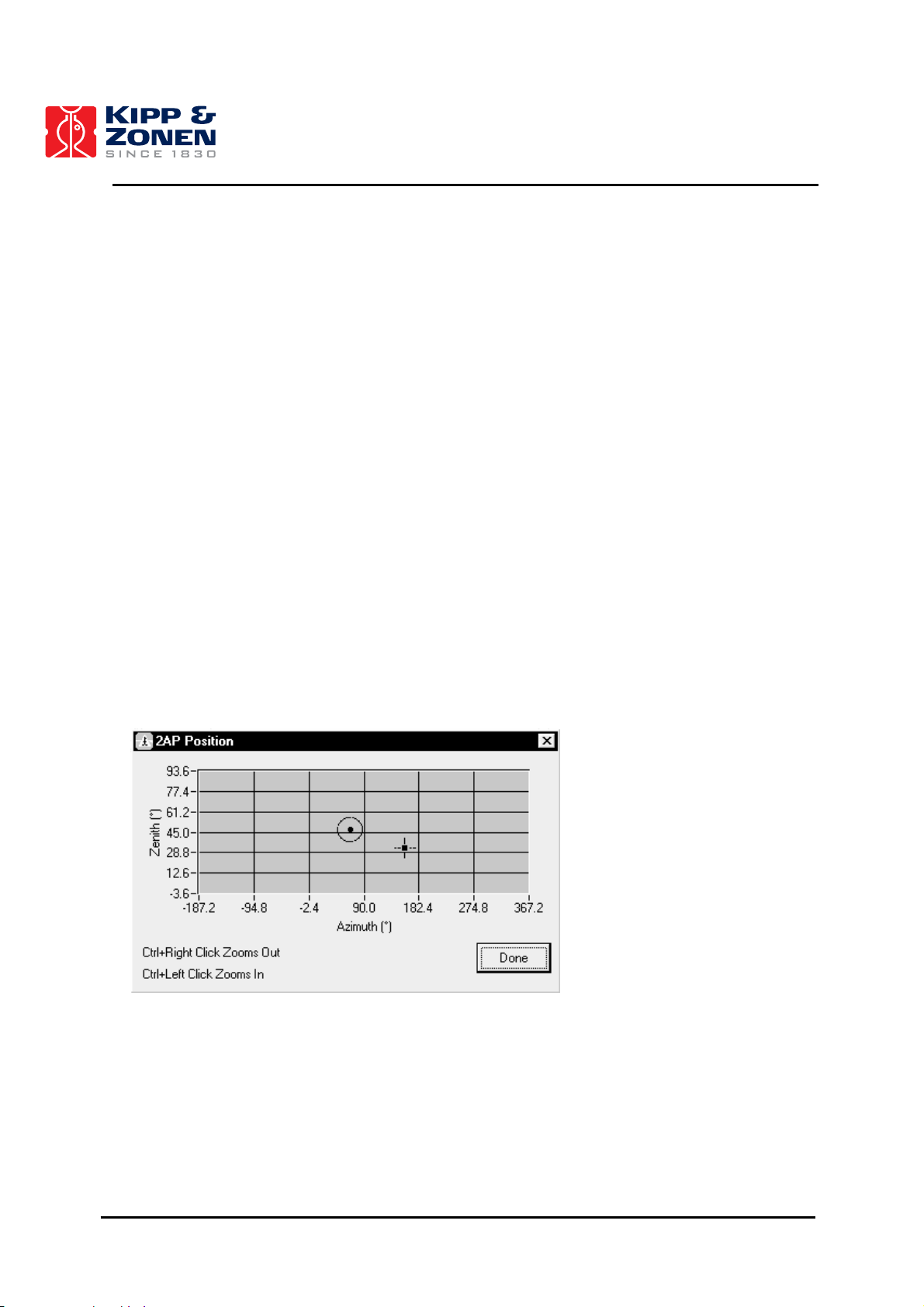
OPERATION
5.3.4 Moving to Targets
There are two primary methods of moving to your defined targets: manually and Cycling.
To execute the targets manually, ensure that Cycling is turned off and select the target name on the
main Positioner window. This can be done by either clicking on the target name or the radio button
to the left of the target name. The instrument will move to that target and remain there. To deselect the target, click on the name or button again.
To turn Cycling on, either select CYCLING|START from the menu or click on the Start Cycling
indicator light. The 2AP will execute the targets in the order that they appear on the list indefinitely
until Cycling is stopped by either selecting CYCLING|STOP from the menu, clicking the Stop
Cycling indicator light, or selecting the Override button.
5.3.5 Manual Override
In instances where a temporary instrument position or a static target is desired for an indefinite
duration, the manual override feature can be used. The Override button is found on the main
Positioner window and can be accessed at any time. If pressed while the unit is Cycling, Override
will take over and cycling will immediately be stopped. If the instrument was On Target when
Override mode was accessed, the target position will be regained once Override is exited, but
Cycling will be disabled.
Refer to figure 5.7 for the Override dialog box. The red circle with the dot in the middle indicates the
current position of the 2AP and the red cross-hairs indicate the desired target position. To move to
a new target while in this mode, either point and click on the new position or drag the red crosshairs.
Figure 5.7: Override Dialog Box
5.3.6 Monitoring 2AP Position During Operation
A position monitor can be used to visually represent the current position of the 2AP in addition to
the main Positioner window. This window can be opened by selecting 2AP|VIEW POSITION in the
main window and can be accessed while the unit is Cycling. It is essentially the same as the
Override box except that no position commands can be made. This dialog box is shown in figure
5.8.
77
Page 79
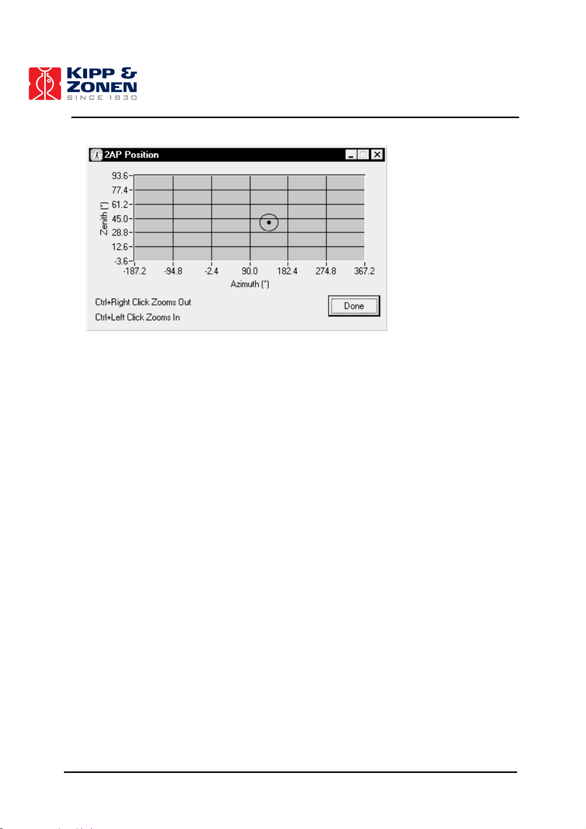
OPERATION
Figure 5.8: 2AP Position Dialog Box
This box can only be used as a monitoring window and therefore no changes or editing of position
can be made. This window can be kept open in addition to the main window to visually display
position information relating to the current target in the cycle. In this way, the most efficient target
order may be realized by noting the overall movement of the 2AP in a complete cycle.
By holding the Control button and right-clicking the mouse, the scaling of the position window will
increase to obtain a more detailed picture of the instrument’s position. Holding the Control button
and left-clicking the mouse will decrease the scaling.
5.3.7 On-line Help and Positioner Information
On-line help files are available at any time by selecting either HELP|CONTENTS or HELP|SEARCH
FOR HELP ON. The first help file is a general guide to assist you in every aspect of the software
operation and the second option is a search facility for any specific topic you may be interested in.
The HELP|ABOUT Win2AP option gives you pertinent information about the version number of the
software that you are currently running. This information may be of particular importance if you
experience software difficulties and you need to contact Kipp & Zonen for assistance.
78
Page 80

OPERATION
5.4 CMD UTILITY
The CMD utility is a program to facilitate sending commands to and displaying responses from the
2AP. Hence it can be used for performing operations including simple tracking tasks. To run the
CMD utility the 2AP must be connected via the serial port of the PC. The CMD utility is intended for
the use of the scientist using the 2AP and the technicians installing the 2AP. The CMD utility has
two intended functions:
• To facilitate sending commands to and displaying responses from the 2AP.
• To provide a tool for verifying the validity of connections to the 2AP and for verifying the low
level message/response operation of the 2AP.
Important:
The CMD program is a low level utility. Using this utility can modify the calibration and equipment
configuration information.
5.4.1 CMD Utility Operation
The CMD utility is integrated in Troubleshooting (page 1, step 7) of the Win2AP software. Pressing
the “Run CMD” button will open the CMD window. Select the right communication port and press
the “Connect” button. The CMD Window is shown in figure 5.9 and described in Table 10.
In chapter 6, reference information is given about the commands that can be used to communicate
with the 2AP.
Figure 5.9: CMD Window in Troubleshooting
79
Page 81

OPERATION
Table 10: CMD Window Elements.
Port
Connect
Disconnect
2AP Status
Serial Number
Password
Command
Send
Reply
Write Config to 2AP
Read Config from 2AP
Create Script/
Close Script
Edit Script
Run Script
Find Password
Auto download 2AP log
Downloading Log
File | Download 2AP Log
File | View 2AP Log /
View log
File | View Event Log
- The serial port that connects the 2AP to the computer.
- Connect to the 2AP on the specified COM port.
- Disconnect from the 2AP.
- The status of the software.
- The serial number of the 2AP obtained by the SE command.
- The password of the 2AP. This is unknown if the password is not 0
or 65535 and the PW command has not been sent.
- Enter the two-letter command to be sent to the 2AP here.
- Send the command entered to the 2AP.
- Communication sent to and received from the 2AP.
- Choose an ini file and write the configuration from that ini file to the
2AP.
- Save the configuration from the 2AP to an ini file. Use this if you
want to create a new Win2AP.ini file.
- Pressing this records all commands sent to the 2AP in a text file.
To end the script press the same button again (the button will now
be called “Close Script”).
- Opens a previously recorded script in Notepad so it can be edited.
- Executes all the commands in the chosen script.
- Searches through all possible passwords until the 2AP’s password
is found. The password is then changed to 65535.
- Automatically downloads the 2AP log when checked.
- Flashes when the log is being downloaded.
- Downloads the 2AP Log (using the LO command).
- View the downloaded 2AP event log.
- View the Win2AP software event log.
80
Page 82

OPERATION
81
Page 83

REFERENCE INFORMATION
6 REFERENCE INFORMATION
This section describes the hardware and software interface between a 2AP and an external control
computer (the controller).
To accomplish this purpose the section will:
a. Describe the physical interface.
b. Describe in detail the information that will be exchanged.
6.1 PHYSICAL INTERFACE
The controller and the 2AP communicate over a serial data link with the following message string
parameters. See section 3.2 for the communication cable connections.
Data Format: 8-bit ASCII
Handshaking: None
Communication Format: RS232C
300 to 9600 Baud (default 9600)
8 Data bits
1 Stop Bit
No Parity
Physical Connection: 3 wire.
6.2 SOFTWARE INTERFACE
The 2AP and the controller communicate in ASCII message strings. The controller initiates all
communication. All commands from the controller start with a command identifier. Only the first two
letters of the command identifier are necessary, but the entire identifier may be sent if desired. The
command identifier may be separated from any parameters by one or more blanks (ASCII 32).
Parameters are separated from one another by one or more blanks.
The 2AP provides framing with forward error detection (FED). A message starts with a twocharacter command identifier and ends with a carriage return (ASCII code 13). Linefeed characters
may be inserted before or after the carriage return; they are discarded. Messages sent by the 2AP
always terminate in a linefeed and a carriage return (ASCII codes 10 and 13 in that order).
As a result of FED framing being used, each message has an additional parameter. This parameter
is a sequence of letters chosen to ensure that the 8-bit sum of all the characters in the message
(excluding linefeeds and the carriage return) is 0. Messages sent by the 2AP always terminate in a
sequence of (possibly no) carets (ASCII 94) followed by the necessary character to derive the
desired sum. The algorithm used to generate this checksum is presented in section 6.4.
Many commands are followed by a one-digit integer specifying which motor the command affects.
The integer 0 means the azimuth motor, 1 means the zenith motor and 2 means the auxiliary motor
(if present in the instrument). Most commands may be followed by numeric parameters. Numeric
parameters are always floating point, with optional decimal places and exponents.
82
Page 84

REFERENCE INFORMATION
Command names are described in the following sections with the two significant letters capitalized.
Only these two letters need be used to specify the command, though the entire word or any portion
more than 2 letters long can be sent to the 2AP if desired. The 2AP ignores the case of characters
in received commands. Commands can be in upper or lower case or any mixture of the two.
Replies from the 2AP are always upper case.
If an unrecognised command, or a command with missing or incorrect parameters, is received the
2AP will respond NO followed by an error code. A complete listing of all error codes and an
explanation for each code is given in section 6.3.
The 2AP is equipped with password protection to ensure that commands which may make
unauthorized changes to critical configuration data are not inadvertently or purposely sent to the
2AP. See the PWord command, section 6.2.1.
6.2.1 Configuration Commands
Sending configuration commands using the CMD utility allows the controller to store information
about the instrument into the 2AP's permanent memory, see section 5.4. These commands are
normally used only in the factory or during maintenance operations.
Changing parameters will affect commands received after the change was implemented. Movement
commands received before the change are not affected, even if the movement does not actually
occur until after the change was implemented
Changing parameters using BA or FU commands may require additional actions for the change to
take effect. For details refer to the descriptions of these commands.
All commands specify positions and times in degrees and seconds. Positions are specified relative
to a user-defined origin. At power-up both motors move to the reference sensor positions.
ACcessory
Retrieve the code indicating which (electronic) accessory is attached. Returns AC <accessory>.
The <accessory> is one of the following:
• 0 no accessory.
• 8 sun sensor.
ACcessory <accessory>
Set the code indicating which accessory is attached. Returns AC. This command is only permitted
after protection has been removed with the PWord command.
AMax
Retrieve the maximum operating acceleration for all motors. Returns AM <acceleration 0>
<acceleration 1>. Acceleration is in degrees/second²
AMax <motor> <acceleration>
Set maximum operating acceleration for the given motor. Returns AM. Out of range values of
<acceleration> are automatically adjusted into range. The maximum permissible value for
acceleration is determined by the VMax setting. This command is only permitted after protection
has been removed with the PWord command.
83
Page 85

REFERENCE INFORMATION
BAudrate
Retrieve the rate at which communication will take place with the controller. On initial power up this
rate is set to the default of 9600 baud. Returns BA <rate>. The <rate> is one of the following:
• 2 for 300 baud.
• 3 for 600 baud.
• 4 for 1200 baud.
• 5 for 2400 baud.
• 6 for 4800 baud.
• 7 for 9600 baud.
BAudrate <rate>
Set the rate at which communications will take place with the controller. Returns BA. This
command is only permitted after protection has been removed with the PWord command. The baud
rate will not actually change until the instrument is reset.
FUnction
Retrieve the code indicating the function for which the 2AP is being used. Returns FU
<function>. The <function> is one of the following:
• 0 no function. The 2AP will not move.
• 1 standard operation. The 2AP moves in response to motion commands.
Homes to (90,90).
• 2 standard operation. The 2AP moves in response to motion commands.
Homes to (90,0).
• 3 reserved for future use.
• 4 suntracking. Following the sun.
• 5 active correction. Following the sun and adjusting clock daily.
• 6 active tracking. Following the sun using the sun sensor for minor adjustment.
• 7 suntracking setup. Following the sun, using the sun sensor for minor
adjustment and adjusting the clock daily.
• 8-255 reserved for future use.
FUnction <function>
Set the code indicating the function for which the 2AP is being used. Returns FU. This command is
only permitted after protection has been removed with the PWord command. If the instrument was
suntracking and is given a non-suntracking function, it will continue to follow the sun until it is sent a
HO command.
LL
Retrieve the latitude, longitude and nominal atmospheric pressure recorded for the site. Returns
LL <latitude> <longitude> <atmosphere>. Latitude and longitude are in degrees while
atmospheric pressure is in millibars.
LL <latitude> <longitude> <atmosphere>
Set the latitude, longitude and nominal atmospheric pressure recorded for the site. Returns LL.
The permissible values for latitude are -90 to 90 with negative values representing South latitude.
The permissible values for longitude are -180 to 180 with negative values representing West
longitude. This command is only permitted after protection has been removed with the PWord
command.
ORigin
Retrieve the origin for all motors. Returns OR <origin 0> <origin 1>. Origins are reported
as degrees clockwise (CW) from the reference sensor. Hence a negative number is used for
origins counter-clockwise (CCW) of the reference sensor.
84
Page 86

REFERENCE INFORMATION
ORigin <motor> <position>
Set the origin for motor position to be <position> angular units clockwise from the reference
sensor. Returns OR. On all subsequent POsition commands, positions are given relative to this
user-defined origin. This command is only permitted after protection has been removed with the
PWord command.
PWord <old>
Allow modification to configuration data. Returns PW <old> if it succeeds and PW if it fails.
Modification remains possible until 5 consecutive minutes elapse without communication. The
parameter <old> must match the four-digit number stored.
PWord
Disallow modification to configuration data. Returns PW.
PWord <old> <new>
Sets the password. Returns PW <new> if it succeeds and PW if it fails. The parameter <old> must
match the four-digit number stored. The parameter <new> must be a four-digit number to replace it.
Modification must be enabled prior to entering this command.
SC
Retrieves the scaling factor for each sun sensor quadrant along with the nominal scaling of the
sensor. The scaling factor is used to convert the voltage from a given quadrant to the intensity that
is needed to create that voltage from that quadrant. The scaling of the sensor indicates the number
of degrees of error required to translate from "centred on the sun" to "no longer able to measure".
Returns SC <aboveLeft> <belowLeft> <aboveRight> <belowRight> <halfScale>.
<aboveLeft> is the multiplier for the quadrant collecting light from the region counter-clockwise in
both azimuth and zenith.
SC <aboveLeft> <belowLeft> <aboveRight> <belowRight> <halfScale>
Sets the scaling for the sun sensor. Returns SC. This command is only permitted after protection
has been removed with the PWord command.
SErial
Retrieves the instrument serial number from permanent memory. Returns SE <number>.
SS
Retrieves the amount of time over which each sun observation takes place and the intensity level
below which the sun is deemed to be obscured. The sun must not be obscured at any time during
an observing period for an observation to be logged. Returns SP <period> <intensity>.
<period> is in seconds. <intensity> is in W/m².
SS <period> <intensity>
Sets the sun sensing parameters. This command is only permitted after protection has been
removed with the PWord command.
STeps
Retrieves from permanent memory the number of stepping units in a complete revolution for all
motors. Returns ST <stepsPerRev 0> <stepsPerRev 1>.
STeps <motor> <stepsPerRev>
Set the number of stepping units in a complete revolution into permanent memory. Returns ST. The
number of stepping units depends on the setting for the motor controller. This command is only
permitted after protection has been removed with the PWord command.
85
Page 87

REFERENCE INFORMATION
TCorrection
Retrieves the time correction parameter. Returns TC <number>. This value is set at the time of
manufacture and corresponds to the error in the CPU crystal frequency in parts per million (ppm).
TCorrection <number>
Sets the time correction parameter. Returns TC. This command is only permitted after protection
has been removed with the PWord command.
TEmperature
Retrieves the temperature zero count. This value is calibrated during manufacture.
TIme
Retrieve the current universal time. Returns TIme <year> <day> <hour> <minute>
<second>. The time specified is Universal Time. The year is full (e.g. 1992), the day is Julian (i.e.
1 through 366), the hour is between 0 and 23.
TIme <year> <day> <hour> <minute> <second>
Sets the internal clock on the 2AP. Returns TI. The year is full (e.g. 1993), the day is Julian (i.e. 1
through 366), the hour is between 0 and 23. This command is only permitted after protection has
been removed with the PWord command.
TL
Retrieves the tilt induced latitude and longitude error of the 2AP once it has been levelled. Returns
TL <latitude> <longitude>. <latitude> gives the degrees of latitude error.
<longitude> gives the degrees of longitude error.
TL <latitude> <longitude>
Sets the measured tilt induced longitude and latitude error of the 2AP. This command is only
permitted after protection has been removed with the PWord command.
VErsion
Retrieve version information for the 2AP. Returns VE <electronics version> <firmware
version>. The electronics version has the form "a.b", where "a" identifies the version of the
electronics board and "b" determines the sensor attached to the Analogue input port. The
possibilities are:
• a=2 a temperature sensor is provided.
• b=0 no other sensors are present.
• b=8 a sun sensor is present.
VMax
Retrieve the maximum operating velocity for all motors. Returns VM <velocity 0> <velocity
1>. Velocity is in degrees/second.
VMax <motor> <velocity>
Set maximum operating velocity for the given motor. Returns VM. Out of range values of
<velocity> are automatically adjusted into range. The VMax setting may reduce the maximum
value of AMax. This command is only permitted after protection has been removed with the PWord
command.
XTent
Retrieves the range for the instrument. Returns XT <ccw limit 0> <cw limit 0> <ccw
limit 1> <cw limit 1> <F0>. This gives the clockwise (CW) and counter-clockwise (CCW)
travel range for each motor (in revolutions relative to the reference sensor).
86
Page 88

REFERENCE INFORMATION
XTent <motor> <ccw limit> <cw limit>
Sets the travel range of the instrument. Returns XT. This range must be set in accordance with the
actual hardware and must be specified in revolutions (e.g. xt 1 -0.273 0.0138 for a range of 97.5
deg to 5 deg). This command is only permitted after protection has been removed with the PWord
command.
6.2.2 Operation Commands
The 2AP carries out movements as a series of cubic functions of position over time. A series of
cubic functions is referred to as a path. A path consists of one or more path segments. Each
segment consists of a cubic function of position against time and a duration for which that function
should apply. The 2AP maintains a queue of path segments for each motor, allowing a controller to
send a complex series of movements to the 2AP and then ignore the 2AP while the movements are
carried out.
The 2AP calculates path segments as movement commands are received and adds the segments
to the queues. All commands except ADjust and CLear and their derivatives (e.g. HOme), take
effect after all previously queued movements have completed. If a motor runs out of path segments
to perform, that motor will decelerate and stop (if it was not already stopped). The 2AP keeps track
of the position and velocity that each motor will have when all queued path segments are
completed.
The CLear, HOme, POsition and MOve commands generate a complete path internally. All
paths generated on the 2AP will stay within the bounds of the operating configuration and cause no
step changes in velocity.
The 2AP is idle when all motors are stopped and no motors have any path segments in their
queues.
Angular values are positive for a clockwise (as seen from above for azimuth and as seen from
azimuth+90° for zenith) sense to the motion or position and are negative for a counter-clockwise
sense.
ADjust
Retrieve the tracking adjustment for all motors. Returns AD <adjustment 0> <adjustment
1>. Adjustments are reported in degrees.
ADjust <motor> <relative position>
Cause the physical <motor> position to be <relative position> further clockwise while the
logical position remains the same. The sum of all adjustments is called the total adjustment. The
parameter <relative position> must be within acceptable limits (-0.21° and +0.21°) and must
not cause the total adjustment to exceed 4°. This command is only permitted after protection has
been removed with the PWord command.
CHeckout <year> <day> <hour> <minute> <second>
Applies to all motors. Adds a path segment or segments to each path so that once the motor
reaches the end of its specified path, it returns to the reference point and remains there until the
real time clock reaches the indicated value.
This has the effect of synchronizing the CPU clock used to drive motion to the accurately
maintained real time clock. Returns CH. If the reference position is found at some point other than
where it is expected (that is if the motor position has somehow slipped) the motor position is
realigned. Once this command is completed, the adjustment has been set to 0. This command is
only permitted after protection has been removed with the PWord command.
87
Page 89

REFERENCE INFORMATION
CLear
Immediately decelerates all motors to a full stop as quickly as possible consistent with the current
AMax value. Throws away all path segments in the queues. Returns CL immediately. This
command is only permitted after protection has been removed with the PWord command.
HOme
Has the same effect as CLear followed by positioning of all motors to the reference sensors and
setting the adjustments to 0. Returns HO immediately and sets bit 0 of the instrument status. Bit 0
is reset after all motors are repositioned. This command is only permitted after protection has been
removed with the PWord command.
MOve <motor> <relative position>
After all outstanding path segments have been processed, move the motor (as quickly as possible,
consistent with the current AMax and VMax values) to the position equivalent to the end position of
the path for that motor (the current position, if the motor is stopped) so that the motor is stopped at
the final position. Returns MO when the path is calculated. This command is only permitted after
protection has been removed with the PWord command.
PAuse <duration>
Applies to all motors. Adds a path segment to each path so that once the motor reaches the end of
its specified path, it stops and remains motionless until <duration> (in seconds, not more than
10 hours) after all motors have become motionless. Returns PA. This command is only permitted
after protection has been removed with the PWord command.
POsition <motor> <absolute position>
After all outstanding path segments have been processed, move the motor to the specified absolute
position (as quickly as possible using the latest operating configuration) so that the motor is stopped
at the specified position. Returns PO when the path is calculated. This command is only permitted
after protection has been removed with the PWord command.
POsition
Retrieve the final position for all motors (that is, the position when all outstanding movement
commands have been processed). Returns PO <position 0> <position 1>.
SYnchronize <year> <day> <hour> <minute> <second>
Applies to all motors. Adds a path segment or segments to each path so that, once the motor
reaches the end of its specified path, it stops and remains motionless until the real time clock
reaches the indicated value. This has the effect of synchronizing the CPU clock used to drive
motion to the more accurate real time clock. Returns SY. This command is only permitted after
protection has been removed with the PWord command.
TRack <motor> <end position> <end velocity> <duration>
Add a single path segment to the queue for the given motor. The path segment is calculated based
on the ending position and velocity of the previous path segment. The path segment lasts for
<duration> time units (not more than 10 hours), and at the end of the segment the motor will be
at the specified position and moving with the specified velocity. This command is only permitted
after protection has been removed with the PWord command.
The initial position and velocity, ending position and velocity, and duration specify a unique cubic
function of motor position over time. The 2AP can be programmed to follow an arbitrary complex
function by approximating the function with a series of cubic interpolations.
Note that it is possible for the controller to specify velocities and accelerations outside the
configured operating parameters using the TRack command. The 2AP checks these bounds and
does not accept commands that will take it outside its operating parameters.
88
Page 90

REFERENCE INFORMATION
WArm
Returns WA. Afterwards restarts the software as though the power had been turned off and then
on. Used primarily for putting any equipment configuration changes into effect. This command is
only permitted after protection has been removed with the PWord command.
6.2.3 Status Commands
These commands deal with retrieving information about the current and past status of the 2AP. Of
special interest in this regard is the log of major events. This is a circular queue of information
about (usually anomalous) events in the recent past. As each new event is encountered it gets
added to the queue. If there is a shortage of memory to store the event, the oldest recorded events
are discarded.
Analogue <source>
Retrieves the signal level on analogue input <source>. Returns AN <source> <level>. It
returns the internal input sensor value in volts.
For electronics version 2, the following sources are defined. Which of these are actually present
depends on which sensor is attached. The VErsion command allows the user to determine which
sensors are present. Sources 0 through 7 are available for all sensors. Sources 12 through 15 are
available for the sun sensor only.
The sources defined are:
• 0 - 7 the voltage at the corresponding ADC port.
• 8 unused.
• 9 unused.
• 10 unused.
• 11 unused.
• 12 active correction sensor segment collecting light from the region counter-
clockwise in azimuth and counter-clockwise in zenith.
• 13 active correction sensor segment collecting light from the region counter-
clockwise in azimuth and clockwise in zenith.
• 14 active correction sensor segment collecting light from the region clockwise
in azimuth and counter-clockwise in zenith.
• 15 active correction sensor segment collecting light from the region clockwise
in azimuth and clockwise in zenith.
• 16-22 unused.
BEgin
Retrieve the time at which the most recent session (reset) began. Returns BEgin <year> <day>
<hour> <minute> <second>. The time specified is Universal Time (see TIme).
CElsius
Retrieves the current internal temperature (in degrees Celsius). Returns CE <temperature>.
CPosition (Current Position)
Retrieves the current position of all motors. Returns CP <position 0> <position 1>. The
reported position includes any adjustment.
IStatus
Returns the status of the 2AP. Returns IS <status>. The status value is in hexadecimal
notation and is divided into a set of 8 flags (bits 0 through 7) and a state field (bits 8 through 15).
89
Page 91

REFERENCE INFORMATION
The 8 flags are interpreted as follows:
• bit 0 instrument is searching for reference.
• bit 1 instrument is operating autonomously.
• bit 2 instrument is below permissible operating temperature.
• bit 3 unused.
• bit 4 unused.
• bit 5 unused.
• bit 6 unused.
• bit 7 unused.
The instrument states are:
• 2 the instrument has failed its RAM test sequence.
• 3 the instrument has failed its ROM test sequence.
• 4 the instrument failed to find a limit sensor.
• 5 the instrument failed to find a reference sensor.
• 6 the FU parameter is not set.
• 10-13 Calculating sun position and pointing at sun, if possible.
• A the instrument is waiting for certain conditions to be met before proceeding.
These conditions are:
- temperature must reach an appropriate level;
- there must be no alarm signal for either motor. See MS response: bit 1;
- reasonable LL command data must be loaded.
• B to E the instrument is resetting (see CL, HO & WA).
• F the instrument is accepting motion commands (not operating autonomously).
Note: Other state field values are for troubleshooting only and should be ignored.
LOg
Retrieves the next log item from the circular queue. Returns LO <text> where <text> is one
of the messages listed in section 6.6.
LOg <pos>
Repositions the location in the circular queue from which the next <text> will be drawn. Returns
LO. There are two alternatives for <pos>. 0 positions to the oldest entry in the circular queue. 1
positions to after the newest entry in the circular queue.
MStatus
Retrieves status of all motors. Returns MS <status 0> <status 1>. The status values are in
hexadecimal notation and are divided into a set of 8 flags (bits 0 through 7) and a state field (bits 8
through 15).
The 8 flags are interpreted as follows:
• bit 0 motor is in motion.
• bit 1 motor Hardware Alarm is activated.
The state field values are interpreted as follows:
• A finding sun.
• B following sun.
Note: Bits 2 through 7 and other State field values are for troubleshooting only and should be
ignored.
90
Page 92

REFERENCE INFORMATION
MX <source>
Starts monitoring the direction for which <source> was maximal. Returns MX.
MX
Retrieves the direction for which <source> was maximal since the most recent MX <source>
command. Returns MX <source> <level> <position 0> <position 1>. The
<source(s)> are defined in the Analogue command. <level> is in volts.
QStatus
Retrieves the current number of path segments in the path for each motor. Returns QS <count
0> <count 1>. The counts are in hexadecimal and in the range 0 to FF.
SL
Retrieves the next sun observation from the circular queue. Returns SL <intensity> <error
size> <error dir> <position0> <position1> <year> <day> <hour> <minute>
<second> where:
• <intensity> gives the average intensity of the sun over the observing period.
• <error size> is the number of degrees between where the sun was detected
and where the instrument calculated the sun would be.
• <error dir> indicates the direction of the error (in degrees). 0° means the sun was
found at a larger azimuth value and 90° means the sun was found at a
smaller zenith value.
• <position 0,1> is the approximate position of motors 0 and 1 at the time of observation.
• <year--second> identifies when the observing period ended.
SL <pos>
Repositions the location in the circular queue from which the next logged sun observation will be
drawn. Returns SL. There are two alternatives for <pos>. 0 positions to the oldest entry in the
circular queue and 1 positions to after the newest entry in the circular queue.
WHere <motor>
Retrieves the end of path information for the specified motor. Returns WH <motor> <position>
<velocity> <time>. Where <time> is the number of seconds from when the WH command is
received until all queued path segments have been completed, and <position> and
<velocity> are the position and velocity of the motor after all path segments are completed.
WPosition (Watermark Position)
Retrieves the watermark position of all motors. Returns WP <position 0> <position 1>.
The watermark position is the most recent position of the motor in which the reference sensor was
not activated. The reported position includes any adjustment.
91
Page 93

REFERENCE INFORMATION
6.3 ERROR CODES
If an unrecognised command or a command with missing or incorrect parameters is received, the
2AP will respond NO followed by one of the following error codes:
• 1 framing error.
• 2 reserved for future use.
• 3 unrecognized command.
• 4 message too long.
• 5 unimplemented instruction or undecodable parameters.
• 6 motion queue is full, movement command rejected .
• 7 travel bounds exceeded.
• 8 maximum velocity exceeded.
• 9 maximum acceleration exceeded.
• A instrument is operating autonomously, command rejected.
• B invalid adjustment size.
• C invalid total adjustment.
• D duration out of range.
• E attempt to read unavailable analogue input.
• F illegal extent specified.
• G attempt to change password protected data.
• Y hardware failure detected.
• Z illegal internal firmware state.
An explanation is given for each code in the following sections.
1 Framing Error:
A message was received by the 2AP that did not sum to zero during the FED processing.
Probable cause: a communication problem. If this error occurs often, it may be that the serial line
is unable to support the selected baud rate. Try lowering the baud rate on the 2AP and resetting
the 2AP.
3 Unrecognised Command:
The 2AP received a command with a two-letter command code that it did not recognize.
4 Message Too Long:
The 2AP received a message exceeding the buffer length.
Probable cause: mismatched baud rates or failure to send carriage return character.
5 Unimplemented Instruction Or Undecodable Parameters:
An undecodable parameter list was encountered in a command that did not have a parameterless
form. Normally when the 2AP receives undecodable parameters it uses the parameterless form of
the message. This message occurs when no parameterless form exists, or when the parameterless
form affects the tracker’s internal state (e.g. LO, SL).
6 Motion Queue Is Full, Movement Command Rejected:
The queue of path segments is full and the 2AP cannot accept this command as a result.
7 Travel Bounds Exceeded:
The command attempts to position the motor beyond its travel limits. The 2AP will not accept this
command.
92
Page 94

REFERENCE INFORMATION
8 Maximum Velocity Exceeded:
The command attempts to operate the motor beyond its velocity limit. The 2AP will not accept this
command.
9 Maximum Acceleration Exceeded:
The command attempts to operate the motor beyond its acceleration limit. The 2AP will not accept
this command.
A Instrument Is Operating Autonomously, Command Rejected:
The command attempts to control the motors whilst the instrument is operating autonomously (e.g.
searching for the reference sensors). Whenever the instrument is operating autonomously it is
using the path queue for its own activities. Consequently, it cannot accept commands at that time.
When the instrument first starts up, it operates autonomously until it finds the reference sensors.
Similarly, in response to HOme and CLear commands, the instrument clears the path queue and
operates autonomously until the command is completed. Finally, whenever the instrument
completes a path, the relevant motor operates autonomously until the motor has been stopped.
B Invalid Adjustment Size:
Physical motor position has been adjusted with an amount greater than the allowable limits. The
maximum adjustment size cannot exceed 4°. An invalid adjustment is reduced to the maximum
adjustment size.
C Invalid Total Adjustment:
Physical motor position has been adjusted with an amount greater than the allowable limits. The
total adjustment must not exceed 4°. Any invalid total adjustment is set to ±4°.
D Duration Out Of Range:
Durations must be positive and may not exceed 65533 internal time slices, slightly over 10 hours.
The SYnchronize command can generate a number of path segments. Each segment entails no
motion for a duration within the above limits. The total wait period cannot exceed 100 path
segments (about 1000 hours) and cannot be negative.
E Attempt To Read Unavailable Analogue Input:
The Analogue command verifies that the appropriate sensor is attached to the analogue port
before attempting to read the sensor. This test determines that the analogue input requested is not
currently available to be read.
F Illegal Extent Specified:
The software travel limits must be specified in revolutions from the reference sensor. The lower
limit must be between -1 and 0, the upper limit between 0 and 1.
G Attempt To Change Password Protected Data:
The PWord command must be entered before any configuration data may be entered. If 5
consecutive minutes elapse between messages the password protection is reinstated. After a cold
start the password is always 0.
Y Hardware Failure Detected:
Indicates an internal hardware failure. Record the circumstances in which this message occurs as a
guide to appropriate repair.
Z Illegal Internal Firmware State:
Indicates an internal software failure.
93
Page 95

REFERENCE INFORMATION
6.4 GENERATING THE FED CHECK SEQUENCE
On receipt of a message, one simply adds up the binary representations of all printable characters.
That sum must be zero (modulo 256). Generating a check sequence of printable characters is not
quite that simple. The following C code shows one way of accomplishing the task:
checkSum = 0;
end = 0;
while (command[end]) // calculate sum so far
checkSum += command[end++];
checkSum += command[end++] = ' '; // separate check bytes
while (checkSum <130 || checkSum> 223) // make all printable
checkSum += command[end++] = '^';
6.5 EVENT LOGS
All messages from the Win2AP software and the 2AP itself are recorded in two event logs. Events
can be a variety of things including reset and instrument status messages, communication errors,
program error codes, etc. Two event logs exist for Win2AP; one for messages downloaded from
the 2AP placed in a file called TWOAP.LOG
file called Win2AP.LOG
To view the 2AP log, it must first be downloaded to the PC using FILE|DOWNLOAD 2AP LOG. The
log can then be viewed by selecting FILE|VIEW 2AP LOG. This log is generally used for diagnostic
purposes only if instrument malfunctions occur. The Win2AP.log for the current session can be
viewed at any time by selecting FILE|VIEW EVENT LOG. This log is generally used for solving
communication problems with the 2AP. The complete Win2AP log file is stored in the same
directory as the Win2AP program.
.
and another for program-related messages placed in a
6.6 LOG ITEMS
The character strings returned by the LOg command are described below. Some messages refer
to motors 0 and 1, which correspond to the azimuth and zenith motors respectively. While each
message is fairly self-explanatory the additional information may be helpful:
all log items reported
All items in the log have been reported. If a LO 1 command is executed this command is normally
the response to the next LO command.
analogue initialisation timed out
During initialisation the analogue inputs could not be read in the time allotted. This indicates a
problem with either the hardware or the firmware.
could not interpret/execute the following input command
A command was received by the 2AP that generated a NO response. The next log item is the
offending message. See section 6.3, and possibly previous log items, for an explanation of why the
command was unacceptable.
94
Page 96

REFERENCE INFORMATION
executing the following input command
A command was received by the 2AP and caused a change to the operation of the 2AP. It was
executed successfully. The next log item gives the text of the message.
few ticks <tick> left in feed interval after overrun number <count>
The software was detected operating dangerously close to its timing limits. If this item occurs while
the software is performing time critical operations (e.g. following the sun) it should be reported to
Kipp & Zonen, along with a copy of the history log which contains this message. Any additional
information concerning the operation of the 2AP at that time should also be provided.
illegal entry in the path
The path contains an illegal entry. This indicates an error in the firmware. Please notify Kipp &
Zonen.
instrument function undefined
The instrument function has not been set (see FU command).
instrument RAM fault
This indicates an instrument hardware problem.
instrument ROM fault
This indicates an instrument hardware problem.
item logged was too large. interpreter code at <address>
An attempt was made to log an item that was too large. This message can be used by the software
engineers to determine what type of item was being attempted.
log item overwritten by later entry
The item that would have been reported has been deleted to make room for a newer item.
Requesting another item will obtain the oldest existing item.
motor <m> attempt to sync to <time>
The indicated motor attempted a synchronization on the path to a time which was already past. The
synchronization may have been generated by some other operation such as a reset or a checkout
command. Normally this condition occurs when the TIme has been reset after a synchronization
path has been downloaded to the 2AP.
motor
<m> failed with code <error code> during attempt to find reference by <time>
The indicated motor encountered a problem attempting to set up a motor reset to complete by the
given time. The error codes are described in section 6.3.
motor <m> lost in location <pos>
The indicated motor failed to find the reference sensor at the position where it expected to find it.
The 2AP will recover automatically by finding the sensor.
motor <m> reference position found at <pos> and set to proper value
During a CHeckout operation on the indicated motor the reference position was detected at the
given position. Addressing was updated so that the reference position once again is the position
defined by the ORigin command.
reset <requested><actual> from <down> until <up>. counts: <tepid><warm>
Once the reset has completed (but before the motors return to the reference positions) this
message is added to the log. It contains the best information available about the reset.
95
Page 97

REFERENCE INFORMATION
• <requested> the reason for the reset:
Cold the CO command;
too many tepid resets in rapid succession;
inconsistent parameters in non-volatile memory.
Tepid the WA command;
too many warm resets in rapid succession.
Warm initial positions are illegal
(probable cause: configuration changes).
No power cycle;
hardware failure;
software failure;
software fault.
• <actual> the kind of reset performed:
Cold non-volatile memory re-initialised.
Tepid all parameters refreshed from non-volatile memory.
Warm all memory assumed valid, motors are reset.
• <down> the last time the 2AP was running before the reset.
• <up> the time at which the 2AP started running again.
• <tepid> the number of tepid resets since the last successful reset.
• <warm> the number of warm resets since the last successful reset.
On a cold reset most of this information reflects default values.
restarting calculations because of configuration change
A configuration change may have changed the expected location of the sun in the sky. It will take
approximately two minutes from this time until the 2AP is "following sun".
restarting calculations error <error> on motor <motor> during <action>
The software recalculated the position of the sun since the <error> during the indicated
<action> and the current calculations have caused an unexpected condition. This can occur
under some rare circumstances such as a need to move the azimuth motor faster than it can go as
the sun travels directly overhead. The <error> code should be reported to Kipp & Zonen if the
message is persistent.
settings restored from NVRAM
On a reset that restores operating parameters from non-volatile memory, this message is logged at
the time of that restoration.
sun sensor window may need cleaning
On this reading an inconsistency was detected in the sun sensor readings. If the message occurs
several times per day (in active mode) over the entire day, the sun sensor window should be
cleaned (occurrences of this log item during sunrise and sunset are normal due to atmospheric
refraction).
time corrected to <time> next correction <x> secs late
The Real Time Clock was set to the indicated time based on operator command or the more
accurate CPU crystal. This automated correction occurs every 8 hours. <x> indicates a further
correction which will be made to correct for mean CPU crystal drift using the TC parameter, see
section 6.2.1. This message is also generated if Time Correction is activated and a clock correction
is made. See section 4.6.5.3.
travel limit encountered
A travel limit sensor suggested that a motor was not in the correct position. The 2AP moved to its
"home" position.
96
Page 98

REFERENCE INFORMATION
97
Page 99

SOLVING PROBLEMS
7 MAINTENANCE
This section describes the recommended maintenance procedures to ensure maximum
performance and a long lifetime of the 2AP GD. Regular lubrication of a Gear Drive is necessary to
prevent severe damage to the gears. Periodically check the condition of all cables and connectors.
Important: Gear Drive lubrication
The worm/spur gear drive for both the azimuth and zenith shafts should be lubricated twice annually
if possible. It is recommended that a lubrication be carried out in the autumn (fall) season to provide
sufficient lubrication during the possible extreme cold condition of the winter months.
Tools required:
Aero Shell Grease #17 is the recommended lubricant to meet the requirements for adequate
worm/spur gear lubrication. Do NOT mix different grease types! Contact Kipp & Zonen if this
lubricant is not available in your area or if you require more information.
The Azimuth worm housing grease fittings (x2) are accessible from the top of the 2AP and the
Zenith worm housing grease fittings (x2) are accessible from the rear, see figure 7.1.
Lubrication procedure:
• Standard hand-pump grease gun with flexible hose (minimum 15 cm).
• Lubricant: Aero Shell Grease #17 (Kipp & Zonen art. no. 8550765).
Important: Lubrication type
• Pump 1-2 ounces (30-60 g) of lubricant into each grease fitting.
• Clean any large amounts of excess grease off the brass gears and the outside of the worm
housing to avoid having the grease fall off during operation and come into contact with other
components inside the 2AP.
98
Page 100

SOLVING PROBLEMS
Azimuth worm
housing grease
fittings (x2)
Zenith worm
housing grease
fittings (x2)
Figure 7.1: Worm Housing Grease Fittings (x4)
99
 Loading...