


KIPOR POWER CO., LTD.
DIGITAL CONVERTER GENERATOR
K G E 2 0 0 0 Tc
K G E 2 0 0 0 Ts c

PREFACE
CONTENTS
Thank you for purchasing our generators.
This manual covers operation and maintenance of the KGE2000Tc, KGE2000Tsc
generator.
All information in this publication is based on the latest product information
available at the time of approval for printing.
We reserve the right to make changes at any time without notice and without
incurring any obligation.
No part of this publication may be reproduced without written permission.
This manual should be considered a permanent part of the generator and should
remain with it if it is resold.
Pay special attention to statements preceded by the following words;
WARNING
CAUTION
NOTE: Gives helpful information.
If a problem should arise, or if you have any questions about the generator,
consult an authorized dealer.
WARNING
Indicates a strong possibility of severe personal injury or
death if instructions are not followed.
Indicates a possibility of personal injury or equipment
damage if instructions are not followed.
Our generators are designed to give safe and dependable
service if operated according to instructions. Read and
understand the Owner's Manual before operating the generator. Failure to do so could result in personal injury or
equipment damage.
1. SAFETY INSTRUCTIONS
2. SAFETY LABEL LOCATIONS
3. COMPONENT IDENTIFICATION
4. PRE-OPERATION CHECK
5. STARTING THE ENGINE
High altitude operation
6. GENERATOR USE
7. STOPPING THE ENGINE
8. MAINTENANCE
9. TRANSPORTING/STORAGE
10. TROUBLESHOOTING
11. SPECIFICATIONS
12. ELECTRICAL WIRING DIAGRAM
1
3
5
9
13
16
17
24
26
31
33
35
36
The illustration may vary according to the type.
13. LIGHT KIT
37
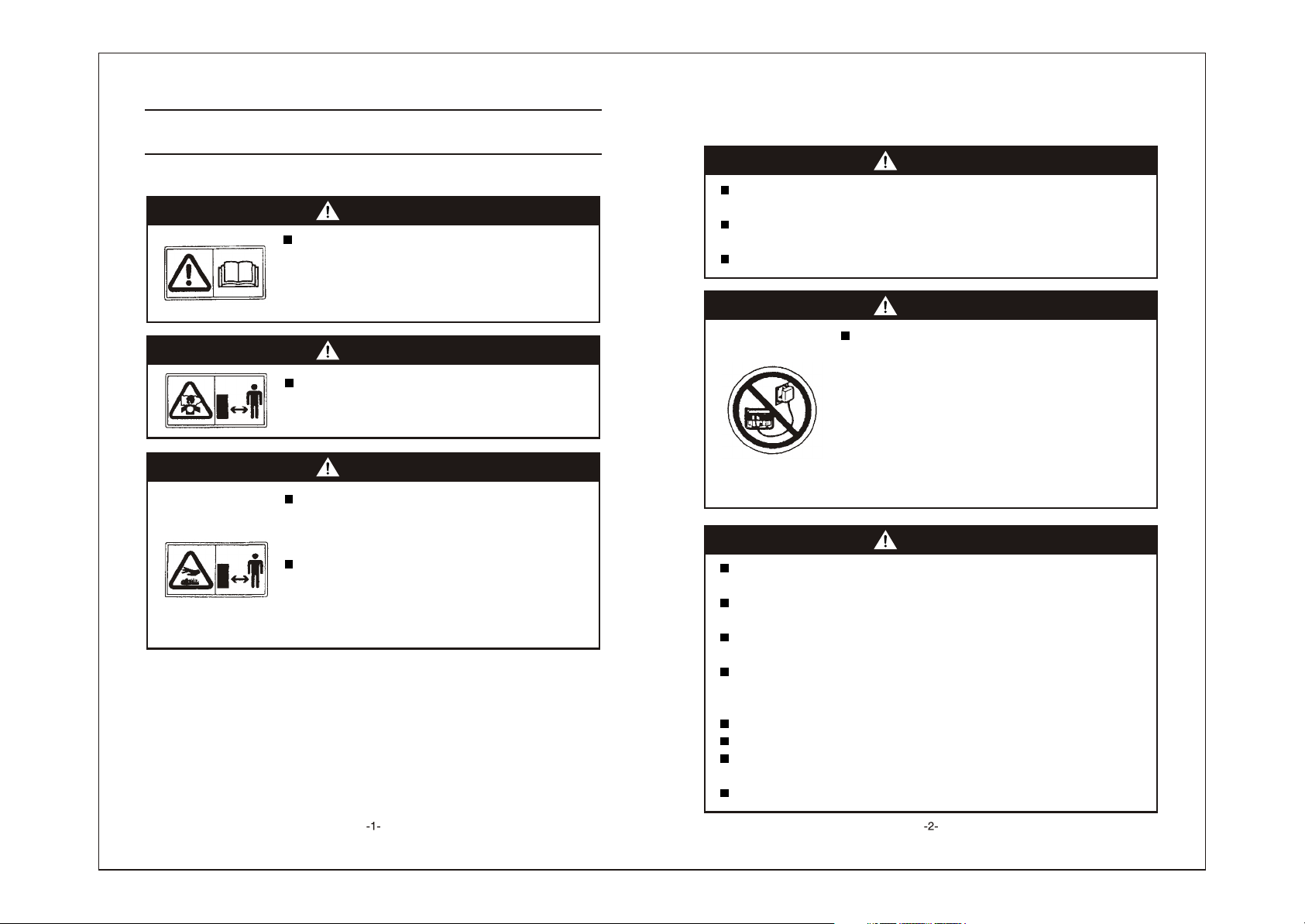
1. SAFETY INSTRUCTIONS
To ensure safe operation
WARNING
Our generators are designed to give safe and depend-
able service if operated according to instructions.
Read and understand the Owner's Manual before op erating the generator. Failure to do so could result in
personal injury or equipment damage.
WARNING
Exhaust gas contains poisonous carbon monoxide.
Never run the generator in an enclosed area.
Be sure to provide adequate ventilation.
WARNING
The muffler becomes very hot during operation and
remains hot for a while after stopping the engine.
Be careful not to touch the muffler while it is hot.
Let the engine cool before storing the generator indoors.
The engine exhaust system will be heated during
operation and remain hot immediately after stopping
the engine.
To prevent scalding, pay attention to the warning marks
attached to the generator.
SAFETY INSTRUCTIONS
To ensure safe operation --
WARNING
Gasoline is extremely flammable and explosive under certain conditions.
Refuel in a well ventilated area with the engine stopped.
Keep away from cigarette, smoke and sparks when refueling the
generator, Always refuel in a well-ventilated location.
Wipe up spilled gasoline at once.
WARNING
Connections for standby power to a building's
electrical system must be made by a qualified
electrician and must comply with all applicable laws
and electrical codes. Improper connections can allow
electrical current from the generator to back feed into
the utility lines. Such back feed may electrocute utility
company workers or others who contact the lines
during a power outage, and when utility power is
restored, the generator may explode, burn, or cause
fires in the building's electrical system.
WARNING
Always make a pre-operation inspection (page 9) before you start the
engine. You may prevent an accident or equipment damage.
Place the generator at least 1m(3ft) away from buildings or other
equipment during operation.
Operate the generator on a level surface. if the generator is tiled, fuel
spillage may result.
Know how to stop the generator quickly and understand operation of all
the controls. Never permit anyone to operate the generator without proper
instructions.
Keep children and pets away from the generator when it is in operation.
Keep away from rotating parts while the generator is running.
The generator is a potential source of electrical shocks when misused; do
not operate with wet hands.
Do not operate the generator in rain or snow and do not let it get wet.
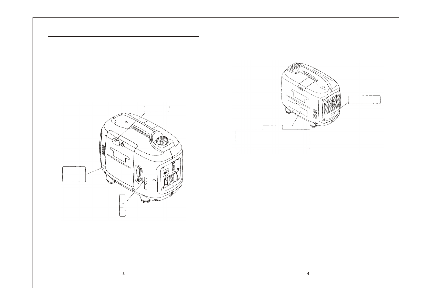
2. SAFETY LABEL LOCATIONS
These lables warn you potential hazards that can cause serious injury. Read the
labels and safety notes and precautions described in manual carefully.
If a label comes off or becomes hard to read, contact your dealer for a
replacement.
CHOKE LEVER
LOW OIL ALARM
HOT CAUTION
SAFETY CAUTION
ENGINE SWITCH
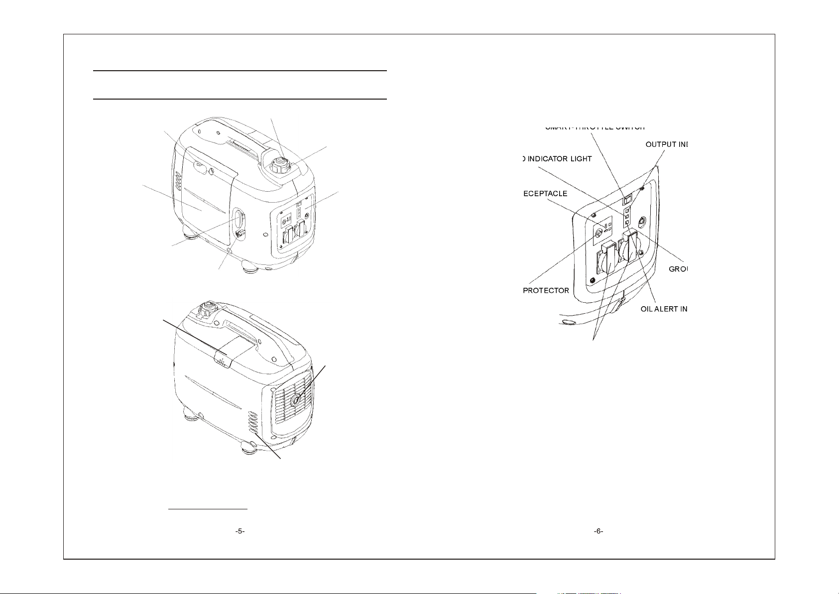
3. COMPONENT IDENTIFICATION
FUEL CAP VENT LEVER
CHOKE LEVER
MAINTENANCE
COVER
FUEL FILLER CAP
CONTROL PANEL
Control panel
E type
SMART-THROTTLE SWITCH
OUTPUT INDICATOR LIGHT
OVERLOAD INDICATOR LIGHT
DC RECEPTACLE
STARTER GRIP
ENGINE SWITCH
SPARK PLUG
MAINTENANCE
COVER
Record the frame serial number in the space below.
You will need this serial number when ordering pars.
Frame serial number:
GROUND TERMINAL
DC CIRCUIT PROTECTOR
OIL ALERT INDICATOR LIGHT
AC RECEPTACLE
MUFFLER
Frame serial number
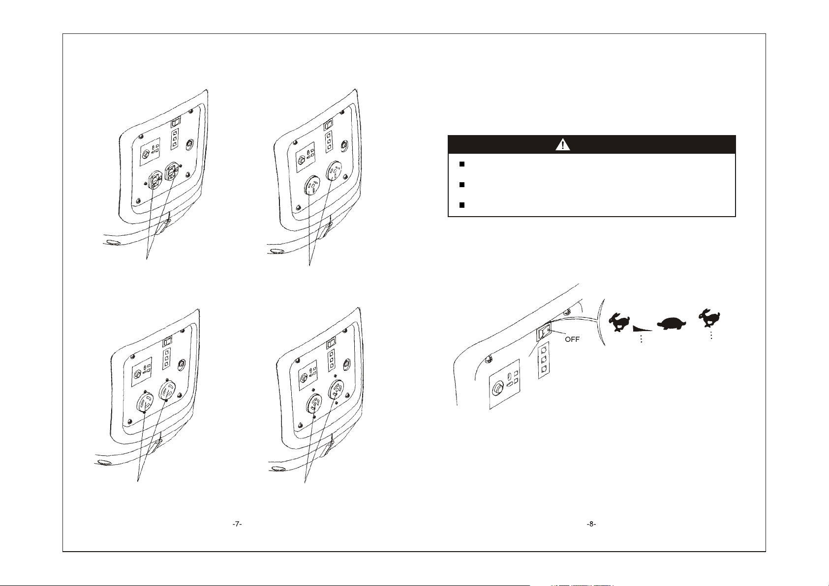
A type (120V) Aus type
AC RECEPTACLE
AC RECEPTACLE
J type A type (240V)
Smart throttle
Engine speed is kept at idle automatically when the electrical appliance is disconnected
and it returns to the proper speed to power of the electrical load when electrical
appliance is connected. This position is recommended to minimize the fuel consumption
while in operation.
WARNING
Smart throttle system does not operate effectively, if the electrical appliance
requires the momentary electric power.
When high electrical loads are connected simultaneously, turn the Smartthrottle switch to the OFF position to reduce voltage vibration.
In DC operation, turn the Smart-throttle switch to the OFF position.
OFF:
Smart-throttle system does not operate. Engine speed is kept over rated speed.
AC RECEPTACLE
AC RECEPTACLE
ON
OFF
ON
OFF

4. PRE-OPERATION CHECK
WARNING
Be sure to check the generator on a level surface with the engine stopped.
1. Check the engine oil level.
WARNING
Using nondetergent oil or 2-stroke engine oil could shorten the engine's service
life.
Use high-detergent, premium quality 4-stroke engine oil, certified to meet or exceed
U.S.automobile manufacturer's requirements for API Service Classification SG, SF.
Select the appropriate viscosity for the average temperature in your area.
SAE Viscosity Grades
10W
SINGLE
VISCOSITY
20W
20
30
40
MULTI
VISCOSITY
-20- -10 0 10 20 30 40
0 20 40 60 80 100
F
AMBIENT TEMPERATURE
Loosen the cover screw and remove the left side maintenance cover. Remove the oil
filler cap, and wipe the dipstick with a clean rag. Check the oil level by inserting the
dipstick in the filler hole without screwing it in.
If the oil level is below the end of the dipstick, refill the recommended oil up to the top of
the oil filler neck.
WARNING
Running the engine with insufficient oil can cause serious engine damage.
NOTE: The Low Oil Alarm System will automatically stop the engine before the oil level
falls below the safe limit. However, to avoid the inconvenience of an unexpected
shutdown, it is still advisable to visually inspect the oil level regularly.
UPPER LEVEL
OIL FILLER CAP
OIL FILLER HOLE
2. Check the fuel level.
Use automotive gasoline (Unleaded or lowleaded is preferred to minimize combustion
chamber deposits).
If the fuel level is low, refuel the fuel tank until the level increased to the specified mark.
Never use an oil/gasoline mixture or dirty gasoline.
Avoid getting dirt, dust or water in the fuel tank.
After refueling, tighten the fuel filler cap seurely.
WARNING
Gasoline is extremely flammable and is explosive under certain conditions.
Refuel in a well-ventilated area with the engine stopped. Do not smoke or
allow flames or sparks in the area where the engine is refueled or where
gasoline is stored.
Do not overfill the fuel tank (there should be no fuel above the upper limit mark).
After refueling, make sure the tank cap is closed properly and securely.
Be careful not to spill fuel when refueling. Spilled fuel or fuel vapor may ignite,
If any fuel is spilled, make sure the area is dry before starting the engine.
Avoid repeated or prolonged contact with skin or breathing of vapor. KEEP
OUT OF REACH OF CHILDREN.
 Loading...