

Page 1
FOREWORD
Congratulations on being an owner of a versatile KIOTI CK20 tractor. This tractor has been designed with the
finest materials and under rigid quality control standards set forth by the DAEDONG engineering department.
Knowledge of tractor operation is essential for many years of dependable service and reliability. This manual
is given to help you familiarize yourself with the CK20 tractor and to give you helpful information about tractor
safety, operation and maintenance. It is the policy of KIOTI to provide each KIOTI tractor owner with a detailed
owner’s manual to help you answer many questions. If the information you are seeking is not found in this
manual, your KIOTI tractor dealer will be happy to help you.
Please feel free to contact DAEDONG IND.CO.,LTD.
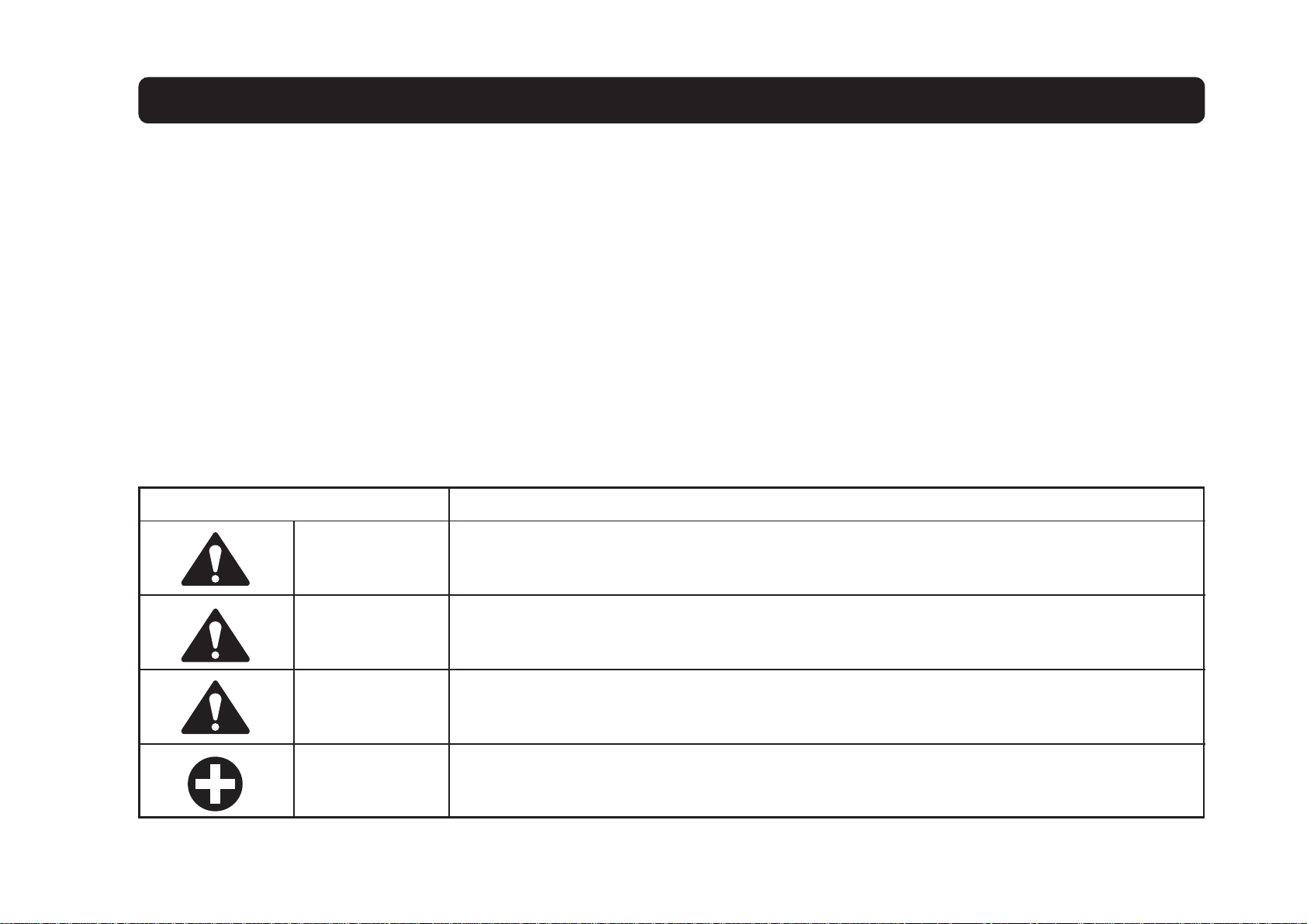
Throughout this manual, you will see text in italics, preceded by the words DANGER, WARNING, CAUTION or
IMPORTANT.
Such text has the following significance.
Signs Description
This mark indicates hazardous situation which, if not observed, may result in death or
DANGER
fatal injury.
This mark should be indicated for most dangerous situations only.
WARNING
CAUTION
IMPORTANT
This mark indicates potentially hazardous situation which, if not observed, may result in
death or moderate injury.
This mark indicates potentially hazardous situation which, if not observed, may result in
minor or moderate injury. And this mark can be used as a warning against unsafe
activities.
This mark indicates emphasis on notable characteristics in working procedures or information on working procedures and technology for convenient use.
Page 2

ABBREVIA TION LIST
Abbreviations
4WD
API
ASAE
ASTM
fpm
Hi-Lo
HST
m/s
P.T.O
RH/LH
ROPS
-
1
m
(rpm)
Definitions
Four Wheel Drive
American Petroleum Institute
American Society of Agricultural Engineers, USA
American Society of Testing and Materials, USA
Feet Per Minute
High Speed-Low Speed
Hydrostatic Transmission
Meters Per Second
Power Take OFF
Right-hand and Left-hand sides are determined by
facing in the direction of forward travel
Roll-Over Protective Structures
Revolutions Per Minute
-
S
SMV
1
(r/s)
SAE
Revolutions Per Second
Society of Automotive Engineers, USA
Slow Moving Vehicle
Page 3
UNIVERSAL SYMBOLS
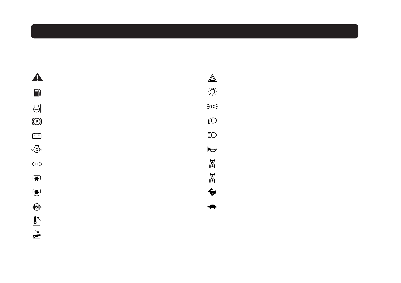
Various universal symbols have been used on the instruments and controls of your KIOTI tractor. Below is a list of the universal
symbols and their meanings.
Safety Alert Symbol
Fuel-Level
Engine Coolant-Temperature
Parking Brake
Battery Charging Condition
Engine Oil-Pressure
Turn Signal
Power Take-OFF Clutch Control-OFF Position
Power Take-OFF Clutch Control-ON Position
Differential Lock
Hazard Warning Lights
Master Lighting Switch
Position Lamps
Headlight-Low Beam
Headlight-High Beam
Audible Warning Device
Four-Wheel Drive-ON
Four-Wheel Drive-OFF
Fast
Slow
Position Control-Raised Position
Position Control-Lowered Position
Page 4

Page 5

CONTENTS
1. SAFETY PRECAUTIONS .......................................................
2. SERVICING ............................................................................
3. SPECIFICATIONS ..................................................................
4 . INSTRUMENT P ANEL AND CONTROLS ..............................
5. PRE-OPERA TION CHECK.....................................................
6. OPERATING THE ENGINE ....................................................
7 . OPERA TING THE TRACTOR ................................................
8. THREE-POINT HITCH & DRA WBAR .....................................
9. HYDRAULIC UNIT..................................................................
10. TIRES, WHEELS AND BALLAST............................................
1 1 . MAINTENANCE ......................................................................
12 . PERIODIC SERVICE ..............................................................
13 . STORAGE ..............................................................................
14. TROUBLESHOOTING...........................................................
15. OPTIONS ...............................................................................
16. INDEX.....................................................................................
Page 6

Page 7

1SAFETY PRECAUTIONS
BEFORE OPERATING THE TRACTOR
OPERATING THE TRACTOR
DRIVING THE TRACTOR
PARKING THE TRACTOR
OPERATING THE P.T.O
USING 3-POINT HITCH
SERVICING THE TRACTOR
TRACTOR SAFETY LABELS
Page 8
1-2 CK20
A careful operator is the best operator.
Most accidents can be avoided by observing certain precautions. To help prevent accidents, read and take these
safety precautions and pay attention to
the job at hand. If you can prevent an
accident in advance, your time will have
been spent well.
BEFORE OPERA TING THE TRACTOR
196O101A
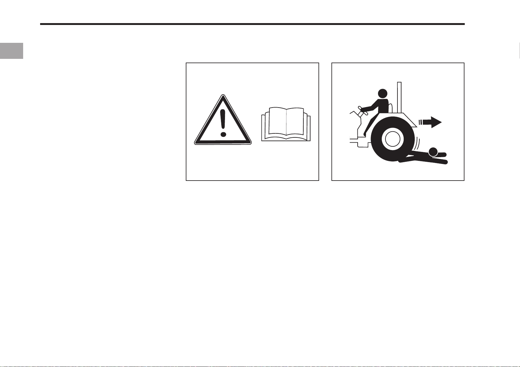
1. It is recommended that you read and
understand this entire manual before
operation of your new tractor. Failure
to do so could result in accidents or
injury.
2. Only persons who are properly trained
should be allowed to operate the
tractor.
3. Read and follow all warning labels and
decals affixed on the tractor.
4. Replace any missing or damaged decals as soon as practical. A list on
decals is shown on page1-14.
5. Keep safety decals clean from dirt and
debris.
196O102A
6. When getting on and off the tractor,
handholds and step plates should always be used. This will help to prevent accidental slips trips and falls.
7. Be sure to scrape off mud or soil from
your shoes before mounting the tractor.
8. Watch where you are going at all times
so that you are able to avoid obstacles that can cause injury or damage to your tractor.
9. When starting the tractor make sure your
path is clear of people to avoid accidents caused by sudden movements.
10.Before making reverse movements
with you tractor you should always
check to see that the path is clear.
Page 9
SAFETY PRECAUTIONS 1-3
1 1.Never operate this tractor or any other
agricultural equipment while under the
influence of alcohol, drugs, or while
fatigued.
12.While working in cooperation with
other tractors always communicate
your intentions.
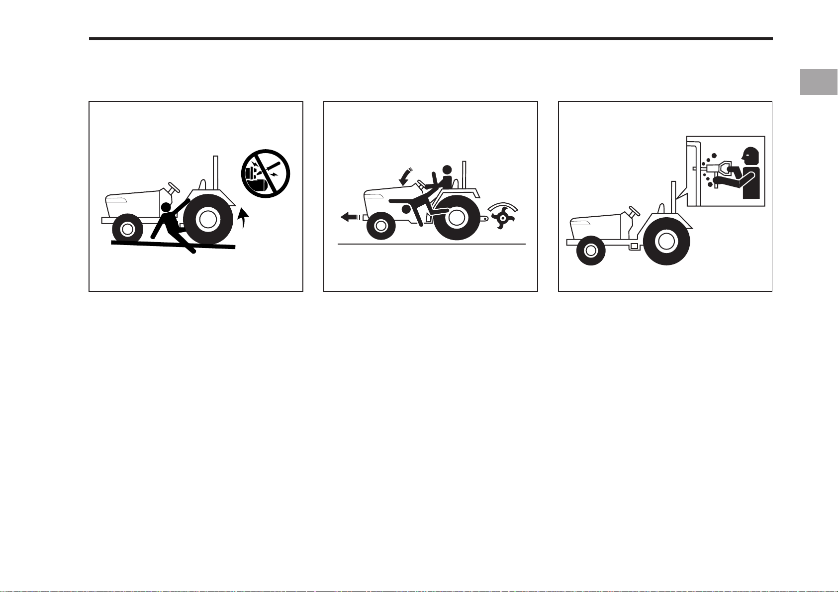
13.Do not start your tractor by shorting
across the starter.
196O104A196O103A
14.Never start the engine while standing
on the ground.
15. Only the operator should ride on the
tractor unless a passenger seat is
installed. Keep bystanderds away
from the tractor while in operation.
196O105A
16.All persons using the tractor should
have knowledge of its proper
operation, and should read this manual
carefully.
17.Never get off the tractor without shutting off the tractor, setting the parking brake, and lowering the implement
to the ground.
18.No alterations should be made to your
KIOTI tractor without first consulting
you KIOTI dealer.
Page 10
1-4 CK20
196O106A
20 . For your safety ROPS with a seat belt
is recommended for most applications.
NOTE
Always use seat belt when the tractor is equipped with a ROPS. Never
use the seat belt when tractor is not
equipped with a ROPS.
(ROPS: Roll-Over Protective Structures)
A ROPS should never be modified by
welding, grinding, or cutting, as this can
weaken the ROPS structure. If any components of the ROPS unit is damaged it
must be replaced.
196O132A
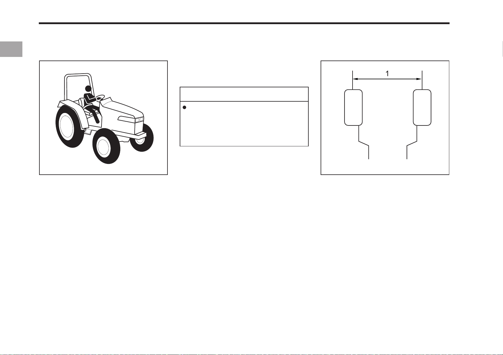
(1) Tread
19.Before starting your tractor you
should disengage the clutch, and insure that all shift levers are in the
neutral position.
If the ROPS unit is removed or loosened
for any reason, the parts should be fitted back to their originals position and all
bolts should be properly torqued.
21.Extra caution should be taken when
driving tractors with narrow tread
widths. For added stability you should
adjust you rear wheel tread width,
see page 12-20.
Page 11
OPERA TING THE TRACTOR
SAFETY PRECAUTIONS 1-5
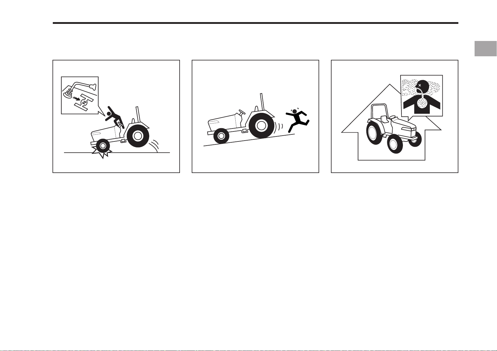
1. Avoid accidental contact with gear
shift levers while the engine is
running. Unexpected tractor movements can result in bodily injury.
196O109A196O108A
2. Do not park your tractor on a steep
incline, and remember to shut off the
engine and P.T.O before dismounting
the tractor.
196O1 10A
3. Do not operate your tractor in an enclosed building without the proper
ventilation. Exhaust fumes can cause
serious injury or death.
Page 12
1-6 CK20
196O1 11A
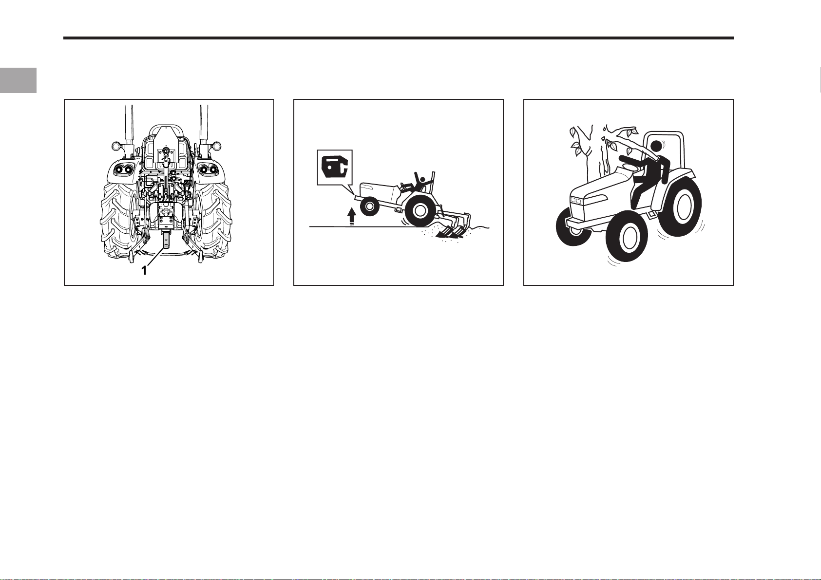
(1) Drawbar
4. Make sure that all pressured lines are
tight before starting the tractor.
5. Pull only from the drawbar. Never hitch
anything to the axle housing or any
other point except the drawbar. Such
arrangements only increase the risk
of serious personal injury or death.
6. If the front of the tractor tends to rise
up when heavy implements are attached to the three point hitch, from
weights should be installed on the
tractor. Do not operate the tractor with
a light front end.
196O1 13A196O112A
7. Do not leave equipment in the raised
position when the vehicle is stopped
or unattended.
8. When using implements or attachments
with your tractor you should first read
their respective owner’s manual. You
should always keep their safe operation procedures in mind.
9. You should be familiar with your
equipment and its limitations.
10. Always use the proper ballast weight
on your tractor when using rear
implements.
Page 13
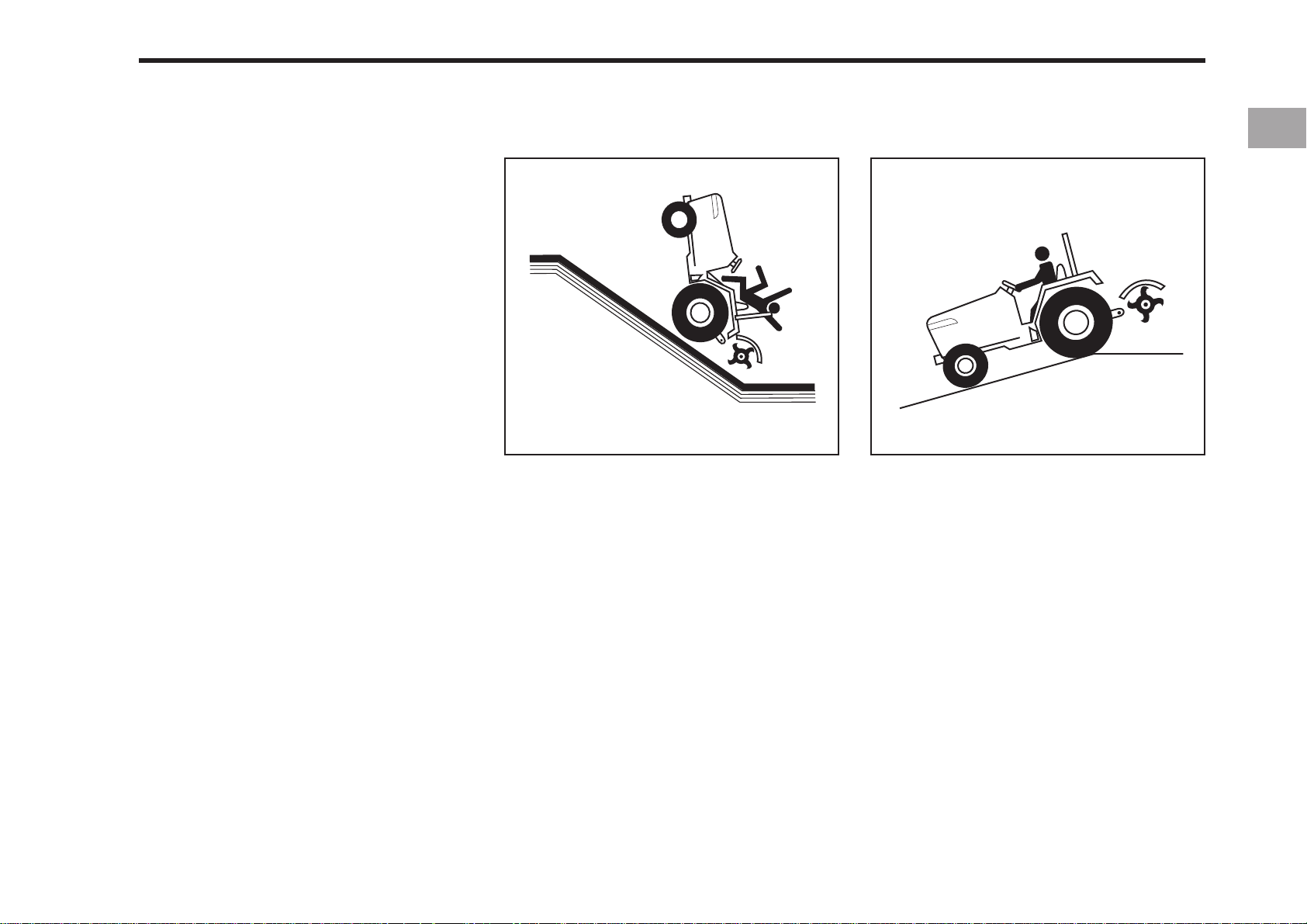
11.Driving forward out of a ditch or steep
inclines can cause the tractor to tip
over backwards. To avoid this you
should back out of these positions.
Four wheel drive tractors can give
you a false sense of security in the
tractors ability to maneuver out of
these positions, so extra caution
should be taken.
12.You should watch for and avoid obstacles at row ends, near trees, and
around other obstructions.
SAFETY PRECAUTIONS 1-7
196O1 14A
13.If abused or used incorrectly your
tractor can become dangerous to you
and bystanders. Overloading your
tractor or using unsafe equipment can
also be dangerous and should be
avoided. Refer to the “Specifications
of Implement Limitation”, which outlines the maximum load for safe tractor operation.
196O1 15A
14. Never try to get on or off a moving
tractor.
15. When working in groups, always let
the others know what you are going
to do before you do it.
16. Never “freewheel”. Disengaging the
clutch or shifting into neutral while
descending a slope could lead to a
loss of control.
17. Do not operate near ditches, holes,
embankments, or other terrain features which may collapse under the
tractor’s weight. The risk of tractor
upset is even higher when the ground
is loose or wet.
Page 14
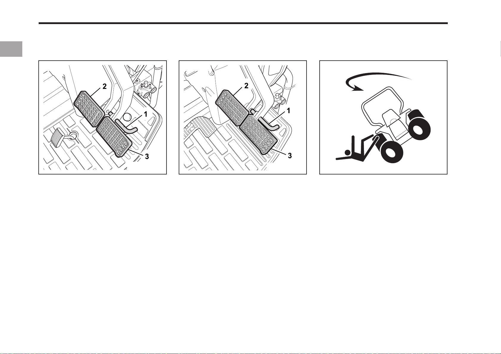
1-8 CK20
DRIVING THE TRACTOR
CK20 CK20H
196O1 16A
(1) Brake Pedal Lock (2) Brake Pedal (L)
(3) Brake Pedal (R)
1. Lock the brake pedals together when
traveling at road speeds. Brake both
wheels simultaneously when making
an emergency stop. Uneven braking
at road speeds could cause the tractor to tip over.
196O1 17A
(1) Brake Pedal Lock (2) Brake Pedal (L)
(3) Brake Pedal (R)
196O1 18A
2. Always slow the tractor down before
turning. Turning at high speed may tip
the tractor over.
Page 15
SAFETY PRECAUTIONS 1-9
P ARKING THE TRACTOR
EU
USA
196O1 19B
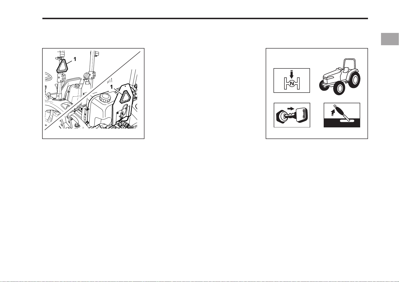
(1) SMV Emblem
3. Make sure that the Slow Moving Vehicle (SMV) sign is clean and visible.
Use hazard lights as required.
4. Observe all local traffic and safety
regulations.
5. Turn the headlights on. Dim them when
meeting another vehicle.
6. Drive at speeds that allow you to maintain control at all times.
7. Do not apply the differential lock while
traveling at road speeds. The tractor
may run out of control.
8. Avoid sudden movements of the
steering wheel as it can cause a loss
of control of the tractor. This risk is
especially great when traveling at
road speeds.
9. Do not operate an implement while the
tractor is on the road. Lock the three
pint hitch in the raised position.
10. When towing other equipment, use a
safety chain and place an SMV emblem on it as well.
196O121A
1. Disengage the P.T.O, lower all
implements, place all control levers in
the neutral position, set the parking
brake, stop the engine, and remove
the key.
Page 16
1-10 CK20
OPERATING THE P.T.O
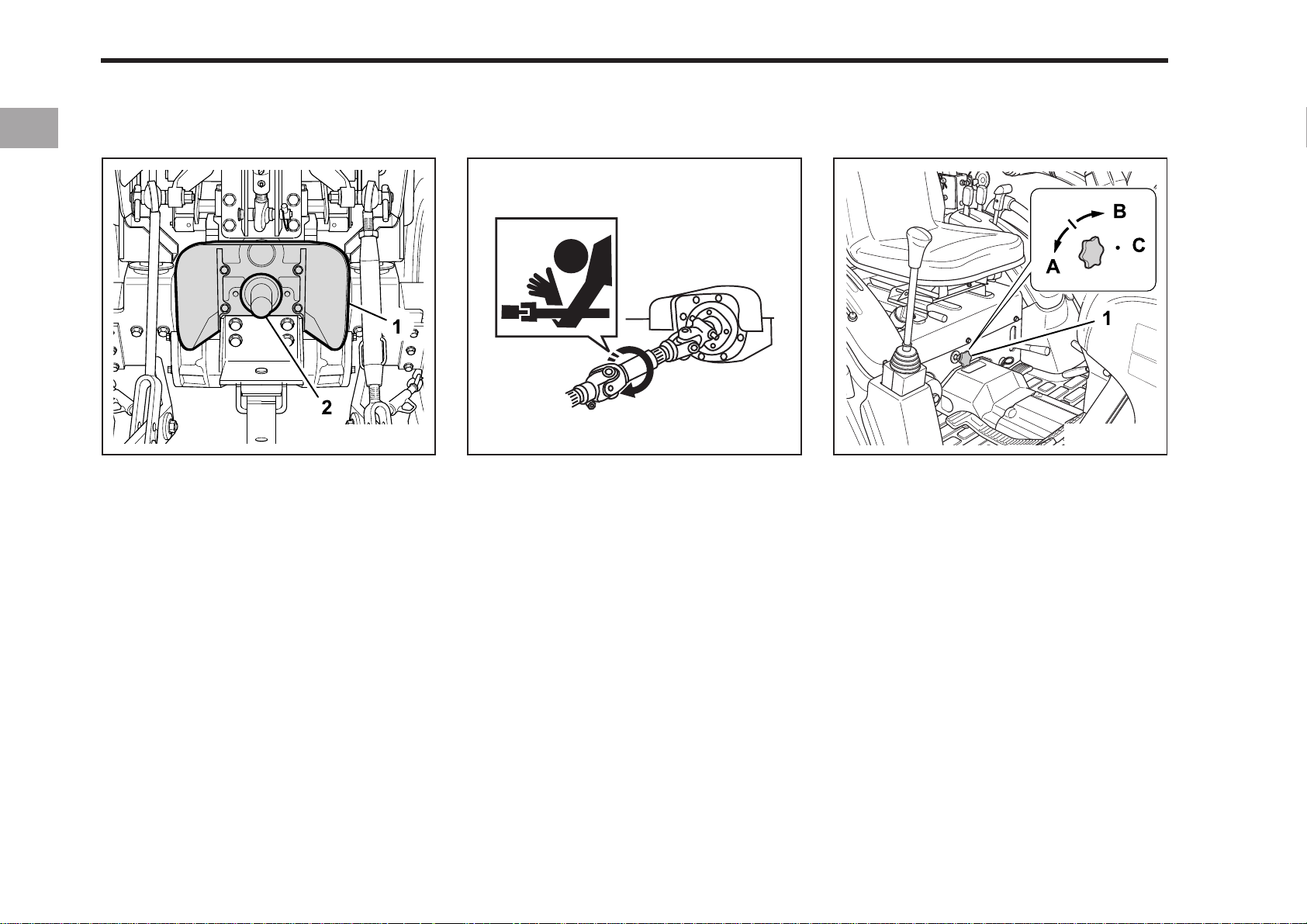
(1 ) P.T.O Shaft Cap (2 ) P.T.O Shaft Cover
USING 3-POINT HITCH
196O123A196O122A
(1) 3-point hitch lowering speed knob
(A) ”FAST” (C) ”LOCK”
(B) ”SLOW”
196O124A
1. Make sure the tractor is completely
stopped, and all moving components
have completely stopped, before
connecting, disconnecting, adjusting,
cleaning, or servicing any P.T.O driven
equipment.
2. Keep the P.T.O shaft cover in place at
all times. Replace the P.T.O shaft cap
when the shaft is not in use.
3. Before installing or using P.T.O driven
equipment, read the maunfacturer’s
manual and review the safety labels
attached to the equipment.
4. When operating stationary P.T.O
driven equipment, always apply the
tractor parking brake and place chocks
behind and in front of the rear wheels.
Stay clear of all rotating parts.
1. Use the 3-point hitch only with equipment designed for 3-point hitch usage.
2. When using a 3-point hitch mounted
implement, be sure to install the proper
counterbalance weight on the front of
the tractor.
3. When transporting on the road, set the
implement lowering control in the
“LOCK” position to hold the implement
in the raised position.
Page 17
SERVICING THE TRACTOR
SAFETY PRECAUTIONS 1-11
In order to service your tractor you must
park it on a flat level surface, set the
parking brake, place the gear shift level
in neutral and stop the engine.
1. Allow the tractor time to cool off before
servicing any part that may have become hot while the tractor was running.
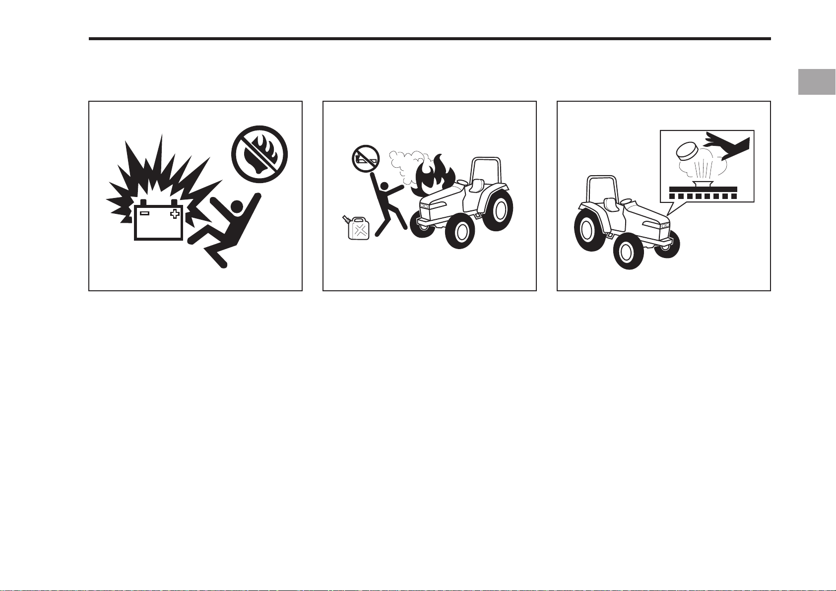
2. You must always stop the engine before refueling the tractor. Avoid overfilling the tractor or spilling the fuel.
3. Do not smoke while working around the
battery or when refueling your tractor.
Keep all sparks and flames away for
the battery and fuel tank. The battery
presents an explosive hazard because
it gives off hydrogen and oxygen… especially when recharging.
196O126A196O125A
4. Before jump starting a dead battery,
read and follow all of the instructions.
5. Keep a first aid kit and fire extinguisher
handy at all times.
196O127A
6. Do not remove the radiator cap while
the coolant is hot. When cool, slowly
rotate the cap to the first stop and allow sufficient time for excess pressure to escape. After all the pressure
is released remove the cap completely.
If your tractor is equipped with a coolant recovery tank, add coolant there
instead of to the radiator.
Page 18

1-12 CK20
196O130A196O129A196O128A
(1) Cardboard (3) Magnifying Glass
(2) Hydraulic Line
7. When working with your tractors electrical components you must first disconnect the battery cables.
8. To ensure that there are no accidents
from sparks you must first disconnect
the negative battery cable.
9. Tire mounting should be done by qualified professionals, with the proper
equipment.
10.Maintaining correct tire pressure is important for the life of your tires. You
should not inflate the tires above the
recommended pressure specified in
the owner’s manual.
11. Securely support the tractor when
changing wheels or the wheel tread
width.
12. Make sure that wheel bolts have been
tightened to the specified torque.
13. Escaping hydraulic fluid under pressure has sufficient force to penetrate
skin, causing serious personal injury.
Before disconnecting hydraulic lines,
be sure to release all residual pressure.
Before apping pressure to the hydraulic system, make sure that all
connections are tight and that all line,
pipes, and hoses are free of damage.
Page 19

196O131A
14. Fluid escaping from pinholes may be
invisible. Do not use hands to search
for suspected leaks;
SAFETY PRECAUTIONS 1-13
Use a piece of cardbord or wood,
instead. Use of safety goggles or
other eye protection is also highly
recommended. If injured by escaping fluid, see a medical doctor at
once. This fluid can produce gangrene or severe allergic reaction.
Page 20
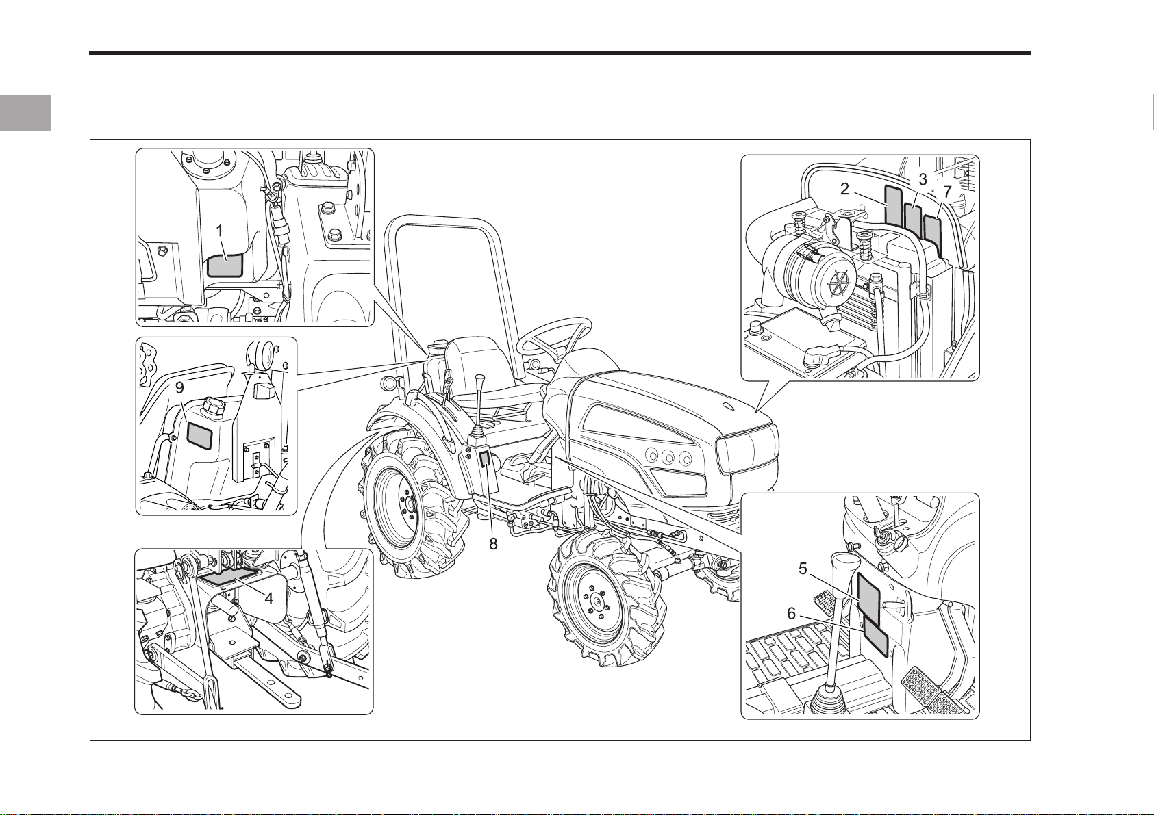
1-14 CK20
TRACTOR SAFETY LABELS
USA
196O134B
Page 21
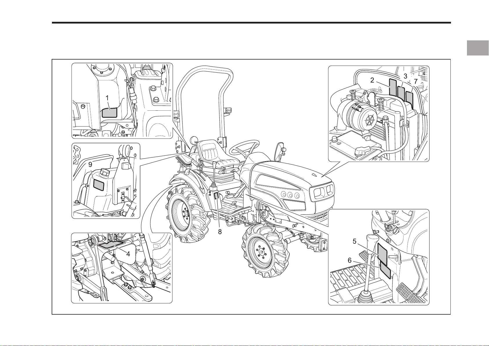
EU
SAFETY PRECAUTIONS 1-15
196O135A
Page 22
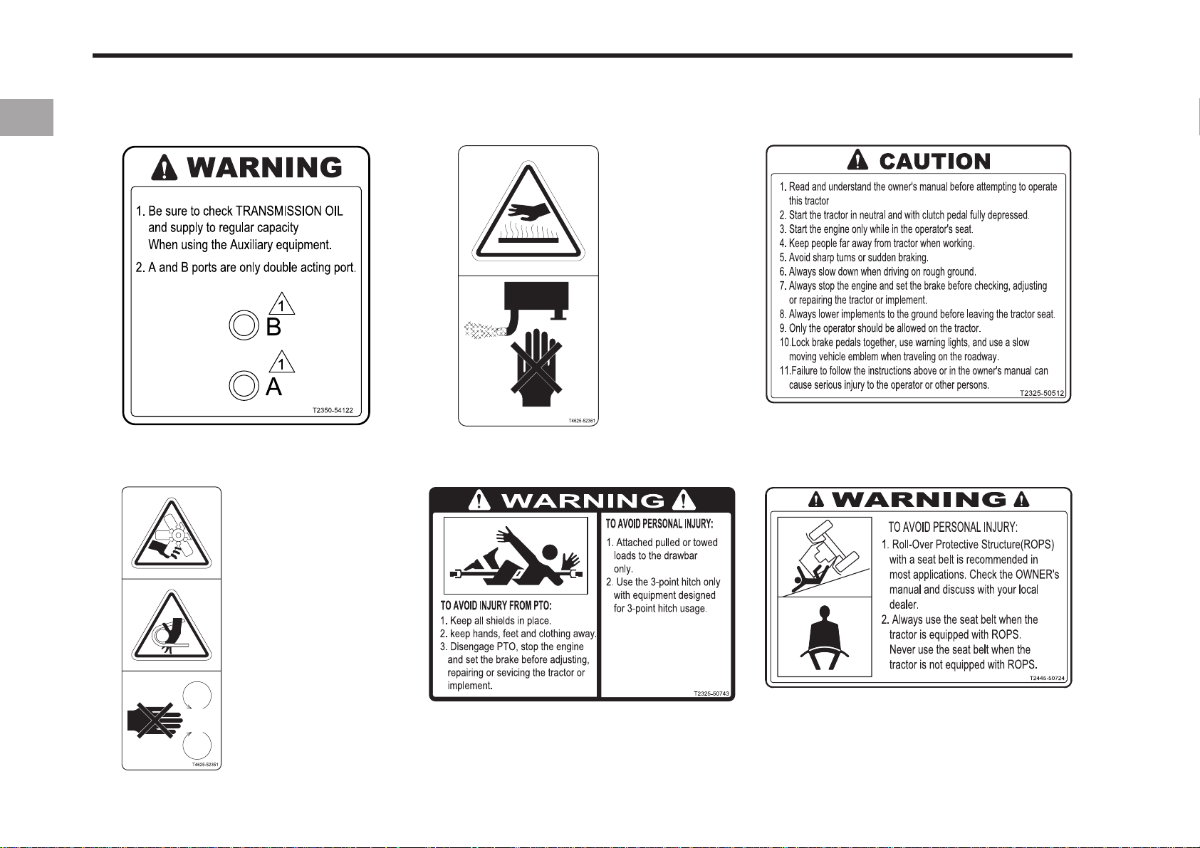
1-16 CK20
(1) Part No. : T2350-54122
(3) Part No. : T4625-52361
(4) Part No. : T2325-50743(2) Part No. : T4625-52351
(5) Part No. : T2325-51962
(6) Part No. : T2445-50724
Page 23
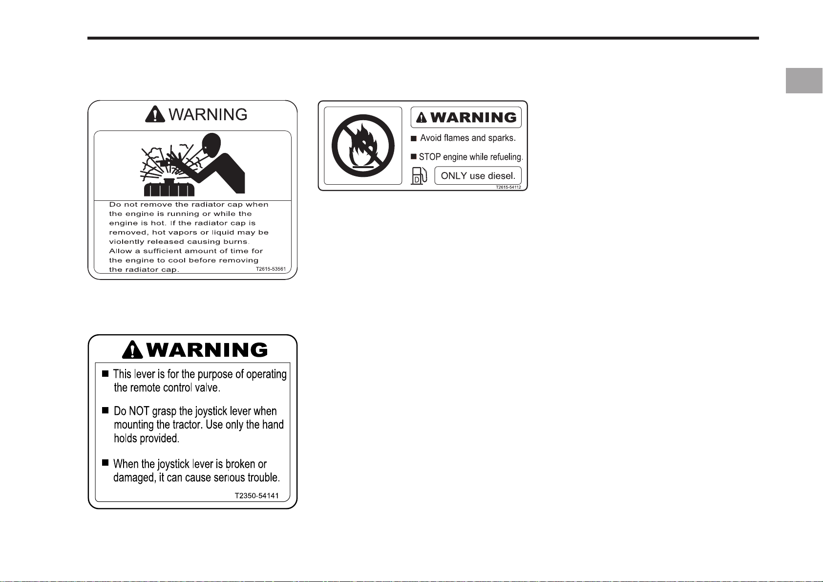
SAFETY PRECAUTIONS 1-17
(7) Part No. : T2615-53561
(8) Part No. : T2350-54141
(9) Part No. : T2615-54112
Page 24

Page 25

2SERVICING OF TRACTOR
SERVICING THE TRACTOR
Page 26
2-2 SERVICING
SERVICING
KIOTI TRACTOR
196OD02B 196OD03A
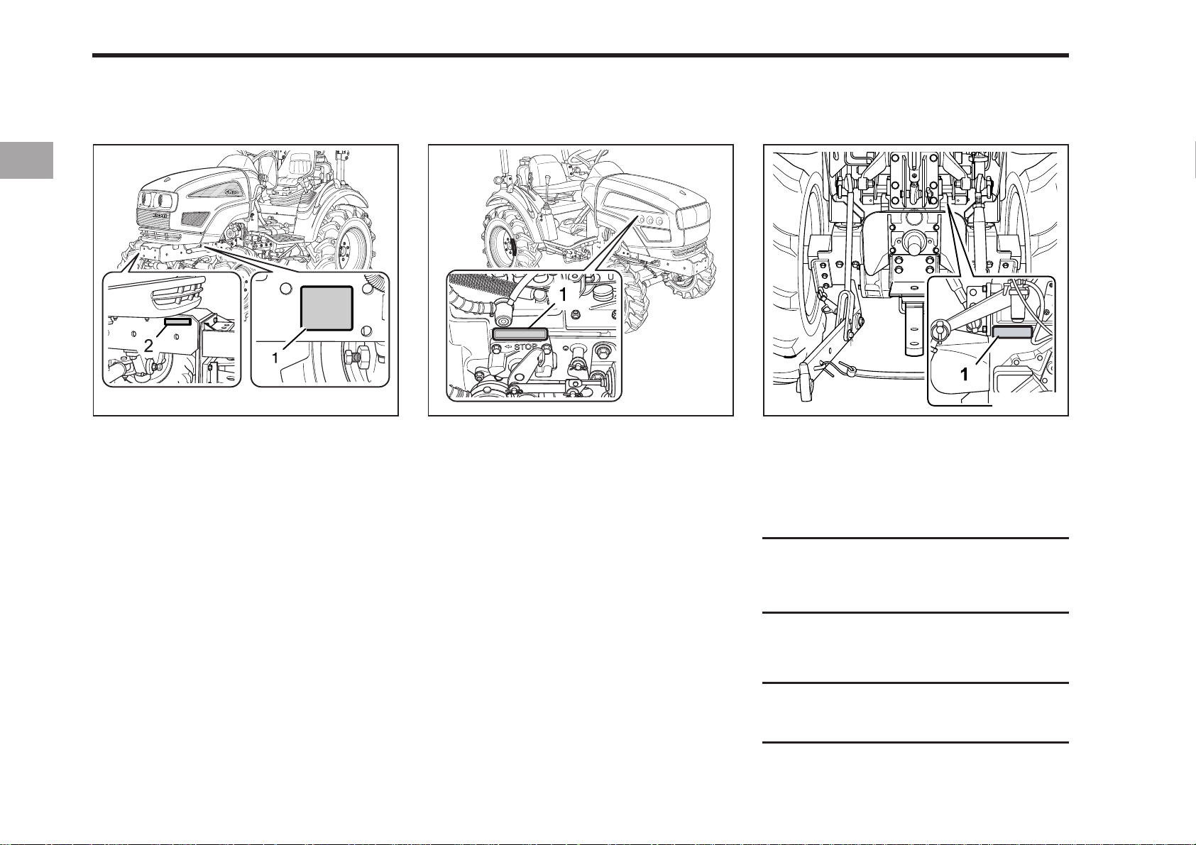
(1) Statutory Plate
(2) Identification No.(EU)
Your dealer is interested in your new tractor and has the desire to help you get the
most value from it. After reading this manual
thoroughly, you will find that you can do
some of the regular maintenance yourself.
However, when in need of parts or major
service, be sure to see your KIOTI dealer.
For service, contact the KIOTI dealership
from which you purchased your tractor or
your local authorized KIOTI dealer.
When in need of parts, be prepared to give
your dealer both the tractor and engine serial numbers.
(1) Engine Serial Number
The tractor serial number is located on the
transmission housing on the left side of
the tractor. The engine serial number is located on the right side of the engine
crankcase. Locate the serial numbers now
and record them in the space provided.
Before using implements not sold by KIOTI
DISTRIBUTOR, contact your nearest
dealer, regarding safety in its application.
196OD04A
(1) Transmission Serial Number
Identification No.
Engine Serial No.
Transmission Serial No.
Date of Purchase
(To be filled in by purchaser)
Page 27

SPECIFICATIONS
3SPECIFICATIONS
IMPLEMENT LIMITATIONS
Page 28
3-2 CK20
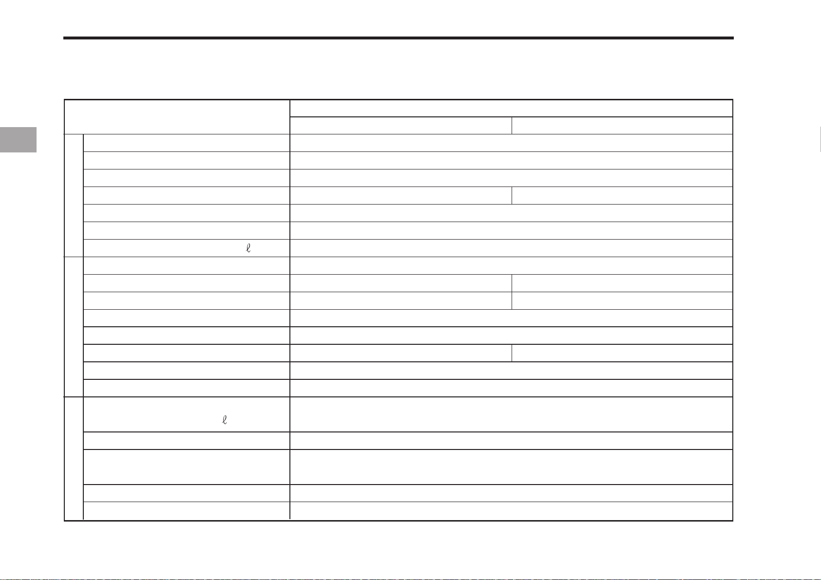
SPECIFICATIONS
Model
MECHANICAL
CK20
HST
Model
Type
Engine gross HP (kW)
P.T.O(Factory observed) HP (kW)/rpm
Engine
Displacement cc (cu.in)
Rated revolution r.p.m min-1
Fuel tank capacity
Clutch
Transmission
Speeds
Differential lock
Brake
Drive trainHydraulic system
P.T.O
Rear (rpm)
Mid (rpm)
Pump capacity (Max. flow rate)
/min (gpm)
(gal.)
Liquid-cooled, 3-cylinder diesel
16.5 (12.3)/2800
synchro/constant
6F 2R
Transmission
1 speed (540 rpm at 2,646 engine rpm)
1 speed (2,000 rpm at 2,706 engine rpm)
3C093
21 (15.7)
15.5 (11.6)/2800
927 (56.6)
2,800
20 (5.28)
Dry type single stage
Hydrostatic
INF.2
Standard
Wet disc type
Live continuous
29 (7.66)
3-point hitch
Maximum lifting capacity
(24in. aft of hitch) kg (lbs)
Hydraulic lift control system
Steering
Cat.I
503 (1,109)
Position control
Hydrostatic
Page 29
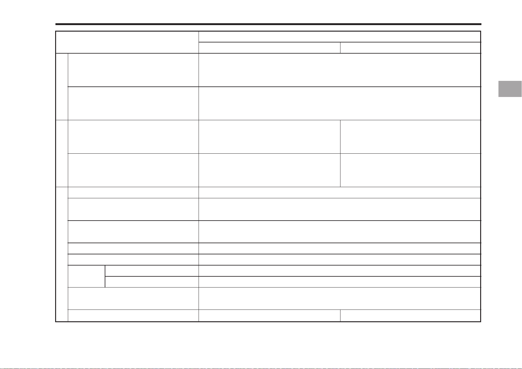
Model
MECHANICAL
SPECIFICATIONS 3-3
CK20
HST
Front (AG, TURF, INDUSTRIAL)
Rear (AG, TURF, INDUSTRIAL)
Standard tire size
Forward (At rated engine rpm)
km/h (mph)
Reverse (At rated engine rpm)
km/h (mph)
Traveling speedsDimensions
Overall length (with 3p) mm (in.)
Overall width (minimum tread)
mm (in.)
Overall height (Top of ROPS)
mm (in.)
Wheel base mm (in.)
6 - 12 (23 x 8.50 - 12, 23 x 8.50 - 12)
9.5 - 16 (33 x 12.5 x 16.5, 12 - 16.5)
1.10 ~ 16.24 (0.68 ~ 10.09)
1.36 ~ 6.31 (0.85 ~ 3.92)
0 ~ 14.97 (0 ~ 9.30)
0 ~ 9.37 (0 ~ 5.82)
2,684 (105.7)
1,121 (44.1)
1,970 (77.5)
1,470 (57.9)
Min. ground clearance mm (in.)
Tread Front mm (in.)
Rear mm (in.)
890 - 935 (35.0 - 36.8)
310 (12.2)
910 (35.8)
Min. turning radius
(with brake) m (Ft.)
Weight (with rops) kg (lbs.)
890 (1,962)
2.3 (7.5)
NOTE: The specifications are subject to change for the purpose of improvement without any notice.
904 (1,993)
Page 30
3-4 CK20
IMPLEMENT LIMIT ATIONS
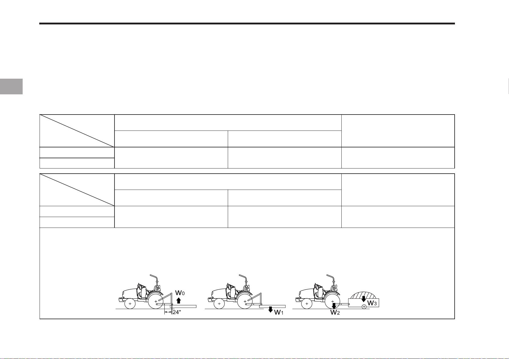
The KIOTI tractor has been thoroughly tested for proper performance with implements sold or approved by KIOTI. Use with
implements which are not sold or approved by KIOTI and which exceed the maximum specifications listed below, or which are
otherwise unfit for use with the KIOTI tractor may result in malfunctions or failures of the tractor, damage to other property and
injury to the operator or others. [Any malfunctions or failures of the tractor resulting from use with improper implements are not
covered by the warranty.]
Item
Tread (max. width)
Lifting Capacity max.
loading weight
Model
Model
CK20
CK20H
CK20
CK20H
Item
Front
910 mm (35.8 in.)
Actual figures
Implement weight W1 and / or size
As in the following list
(shown on the next page)
Max. Drawbar Load W
Rear
940 mm (37 in.)
250 kg
(551 lbs.)
(24 in. aft of hitch)
503 kg
(1,109 lbs)
Trailer loading weight
W
3
2
Max. capacity
812 kg
(1,792 lbs.)
Lifting Capacity max. loading weight ...................... The max. allowable load which can be put on the 24 in. aft of hitch : W
Implement weight ....................................................... The implement’s weight which can be put on the lower link : W
Max. drawbar load ..................................................... W
2
Trailer loading weight................................................ The max. loading weight for trailer (without trailer’s weight) : W
1
3
0
NOTE: Implement size may vary depending on soil operating conditions.
196O301A
Page 31
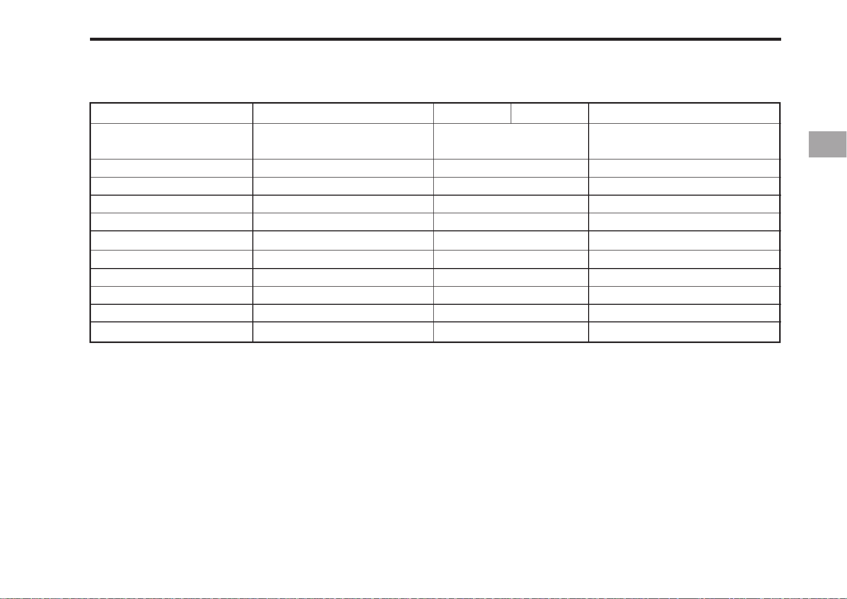
SPECIFICATIONS 3-5
Implement
Loader
Backhoe with sub frame
Mid Mower
Tiller
Bot blade
Rear Blade
Rotary cutter
Belt fuard
Chain guard
Bale transport
Core Aerator
Remarks
Max. Bucket width mm(in)
Max. Diging depth mm(ft.in)
Max. Cutting width mm(in)
Max. Cutting width mm(in)
Max. Cutting width mm(in)
Max. Cutting width mm(in)
Max. Cutting width mm(in)
Max. Cutting width mm(in)
Max. Cutting width mm(in)
Max. Width mm(in)
Max. Width mm(in)
CK20 CK20H
1219.2(48),1371.6(54)
1955.8(6.5) and below
1524(60) and below
1193.8(47) and below
1219.2(48) and below
1524(60) and below
1320.8(52),1524(60)
1320.8(52),1524(60)
1320.8(52),1524(60)
1219.2(48) and below
1219.2(48),1524(60)
Remarks
Operating Capa.300kg(660lbs)
and below
Do not use 3 point hitch backhoe
Page 32

Page 33

INSTRUMENT PANEL
INSTRUMENT PANEL, SWITCHES AND HAND CONTROLS
4
AND CONTROLS
FOOT AND HAND CONTROLS
Page 34
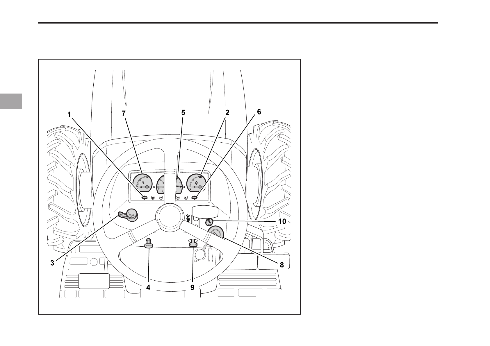
4-2 CK20
INSTRUMENT PANEL, SWITCHES AND HAND CONTROLS
(1) Left Turn Indicator
(2) Cooling Water Temp. Gauge
(3) Turn Signal Switch & Light Switch
(4) Hazard Lamp Switch
(5) Engine Revolution Gauge
(6) Right Turn Indicator
(7) Fuel Gauge
(8) Key Switch
(9) Engine Stop Knob
(10) Horn Switch(only EU)
196O401B
Page 35
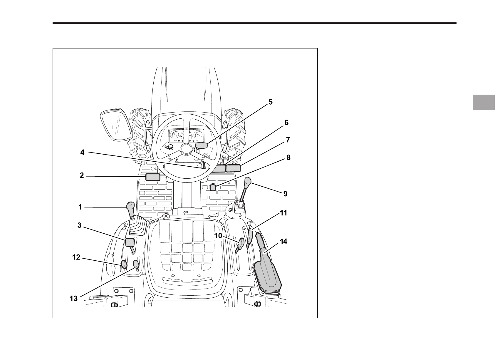
FOOT AND HAND CONTROLS
INSTRUMENT PANEL AND CONTROLS 4-3
CK20
(1) Shuttle Shift Lever
(2) Clutch Pedal
(3) Hi-Lo Shift Lever
(4) Parking Brake Lock Lever
(5) Hand Throttle
(6) Brake Pedal (L)
(7) Brake Pedal (R)
(8) Foot Throttle (M)
(9) Joystick Lever
(10) Double Acting Lever (A, B)
(11) Hydraulic Control Lever
(12) Mid P.T.O Shaft Lever
(13) Rear P.T.O Shaft Lever
(14) Handbrake(only EU)
NOTE : The rearview mirror and the seat
are only for the EU spec.
196O404B
Page 36
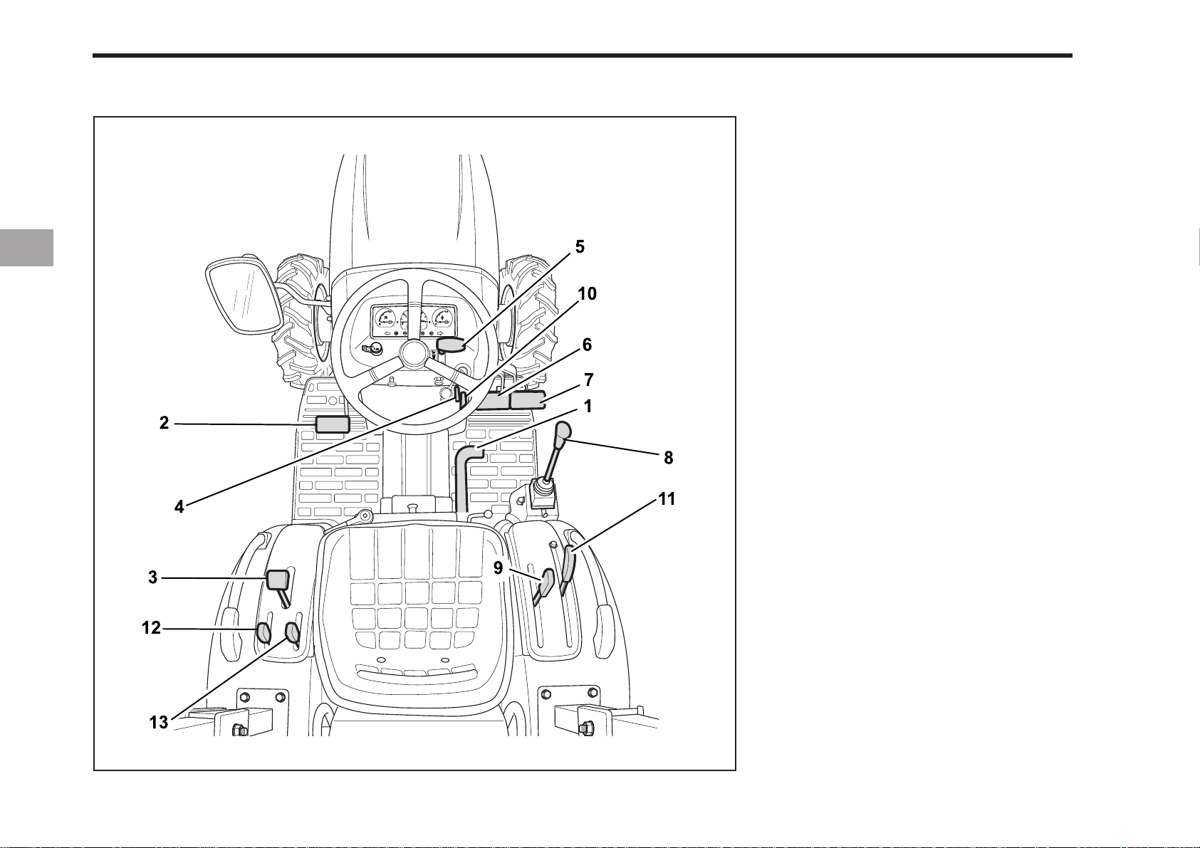
4-4 CK20
CK20H
(1) Forward/Back Ward Shuttle Pedal
(2) Clutch Pedal
(3) Hi-Lo Shift Lever
(4) Parking Brake Lock Lever
(5) Hand Throttle
(6) Brake Pedal (L)
(7) Brake Pedal (R)
(8) Joystick Lever
(9) Double Acting Lever (A, B)
(10) Speed Set Lever
(11) Hydraulic Control Lever
(12) Mid P.T.O Shaft Lever
(13) Rear P.T.O Shaft Lever
NOTE : The rearview mirror and the seat
are only for the EU spec.
196O403B
Page 37

5PRE-OPERATION
DAILY CHECK
Page 38
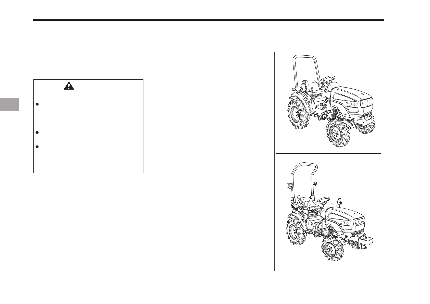
5-2 CK20
DAIL Y CHECK
CHECK ITEM
It is a good practice to know the condition
of your tractor before you start it. You
should do routine check before each use.
CAUTION
To avoid personal injury:
Be sure to check and service the
tractor on a level surface with the
engine shut off and the parking
brake “ENGAGED”.
Refuel (See “DAILY CHECK” in periodic service section.)
Care of danger, warning and caution labels (See “DANGER, WARNING AND CAUTION LABELS” in safe
operation section.)
- Do a walk around inspection.
- Check the engine oil level
- Check the transmission oil level
- Check the coolant level
- Clean the grill and radiator screen.
- Check the air cleaner and evacuator
valve.
- Check the brake pedal
- Check all dash gauges and indicators
- Check head lights, tail lights, and all
working lights.
- Check accessible wiring harness for
any damage.
- Check the seat belt and ROPS for
damage.
- Refuel (See “daily check” in the periodic service section)
- Check all danger and warning labels.
USA
EU
196O405A
Page 39

STARTING THE ENGINE
STOPPING THE ENGINE
6OPERATING THE ENGINE
WARMING UP
JUMP STARTING
Page 40
6-2 CK20
CAUTION
To avoid personal injury:
You must read and understand
the warning and caution labels on
your tractor.
Proper ventilation is required
when operation your tractor inside a building or enclosed area.
Remember that exhaust fumes
can be deadly.
Never start your tractors engine
while standing on the ground.
This can prevent unexpected accident from happening.
IMPORTANT
ST ARTING THE ENGINE
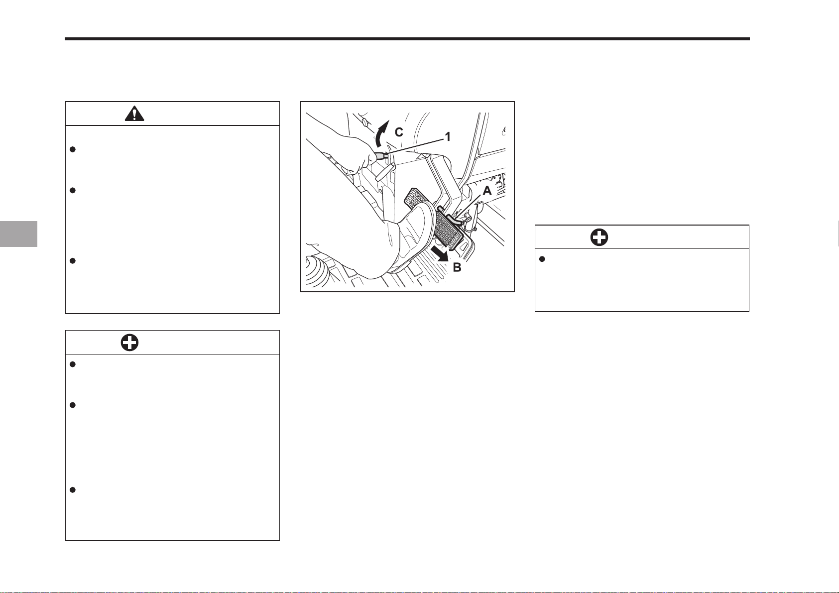
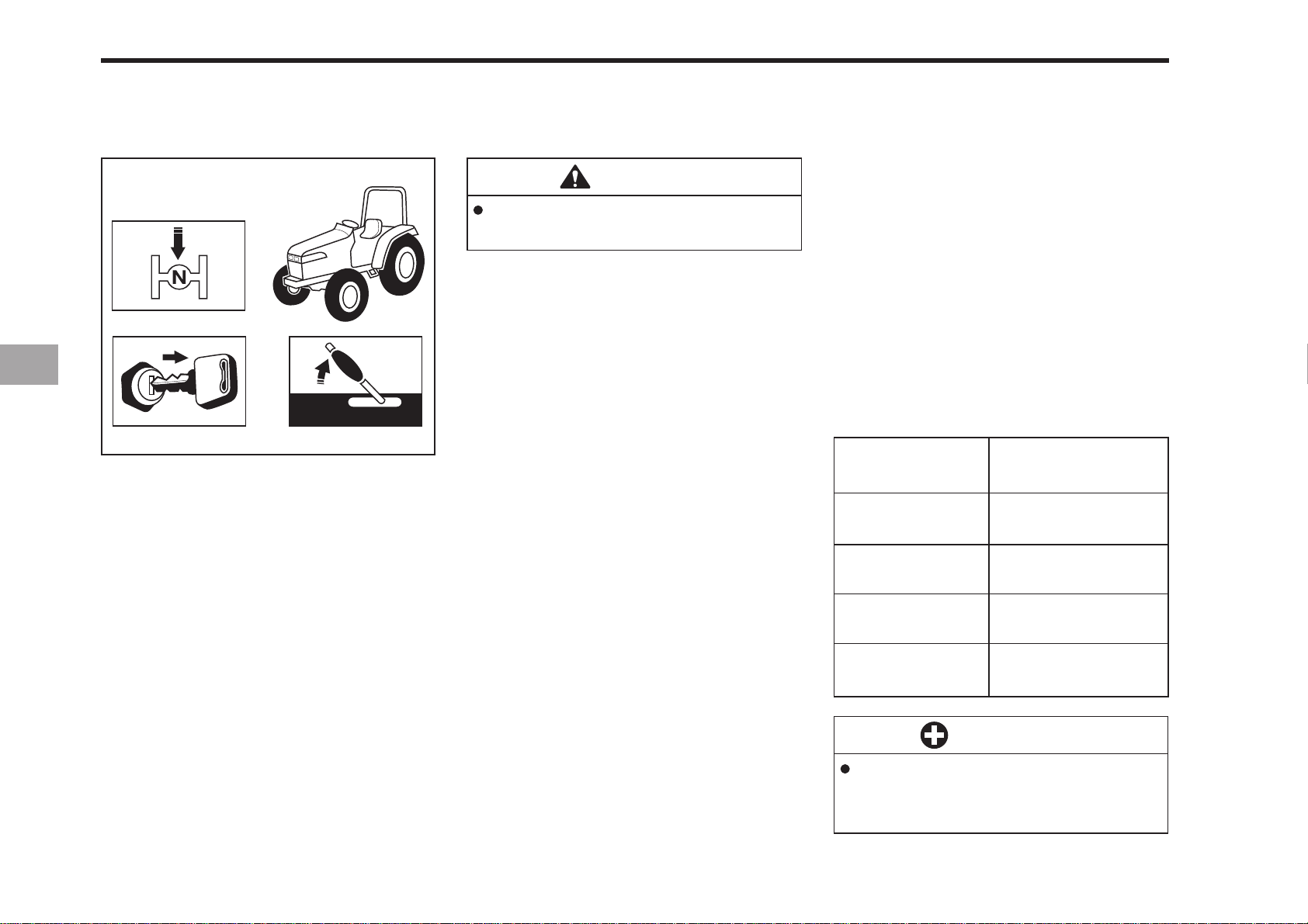
(1) Parking Brake Lever
(A) Interlock the Brake Pedals
(B) “DEPRESS”
(C) “PULL”
196O601A
MAKE SURE THE P ARKING BRAKE
IS SET
1. To set the parking brake;
1) interlock the brake pedals
2) Depress the brake pedals
3) Latch the brake pedals with the
parking brake lever.
2. To release the parking brake you
should press the brake pedals again.
IMPORTANT
Make sure that the parking brake
pedals are fully depressed before pulling the parking brake lever up.
Using starting fluid or ether to start
your tractor will cause damage and
void your tractors warranty.
A good way to start your tractors
engine after a long storage period
you should pull the stop knob and
turn the key over. This will allow time
for oil to reach every part of the tractors engine before starting.
To avoid damage to the starter and
battery you should never continuously start your tractor for more
than 30 second at a time.
Page 41
OPERATING THE ENGINE 6-3
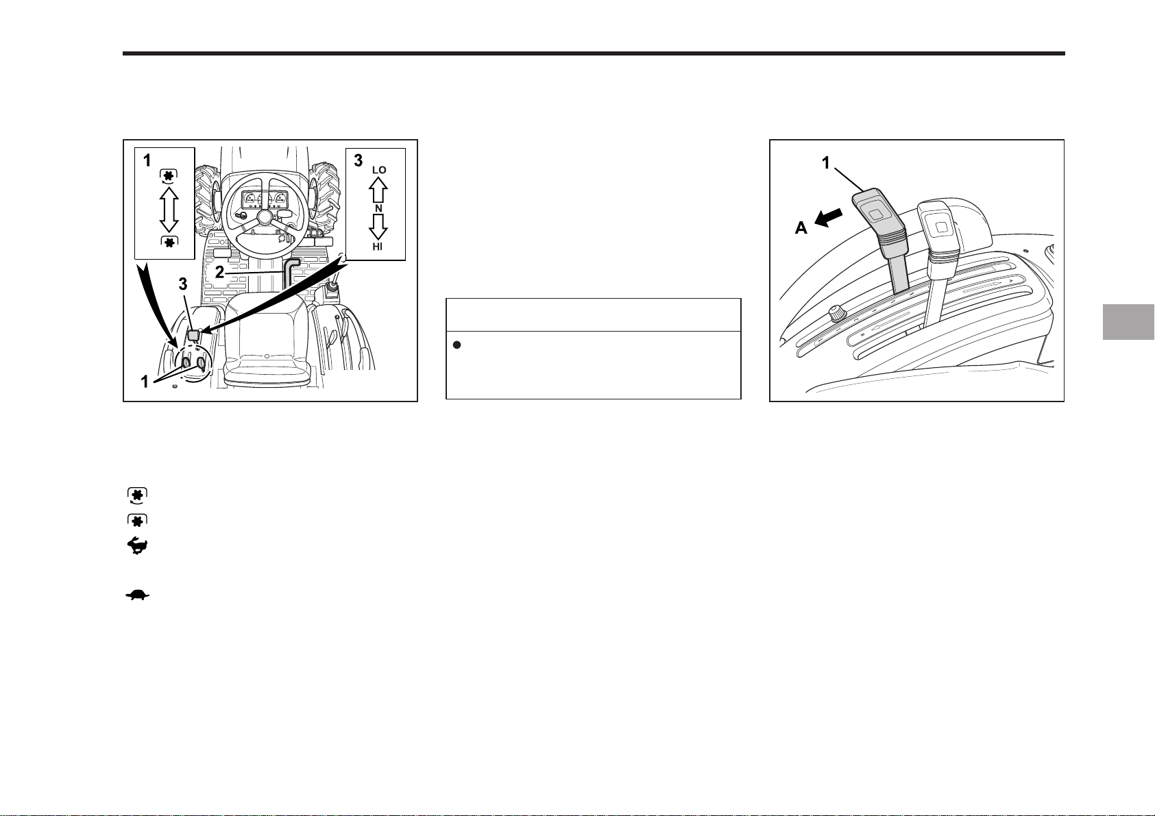
(1) P.T.O Clutch Lever
(2) Speed Control Pedal
(3) Range Gear Shift Lever (Hi-Lo)
“ON”
PLACE THE P.T.O CLUTCH LEVER IN “OFF” POSITION.
PLACE THE SPEED CON
TROL PEDAL IN “NEUTRAL”
POSITION.
PLACE THE RANGE GEAR
SHIFT LEVER (HI-LO) IN
“NEUTRAL” POSITION.
NOTE
The speed control pedal automatically
return to neutral when the operator’s
foot is released from the pedal.
MOVE THE HYDRAULIC
CONTROL LEVER FORWARD.
196O603A196O602A
(1) Hydraulic Control Lever
(A) “DOWN”
To lower implement, move the hydraulic
control lever forward.
“OFF”
“HI”
(N) “NEUTRAL POSITION”
“Lo”
Hydraulic control lever is automatically
returned to neutral position when implement is down at lowest position.
Page 42
6-4 CK20
SET THE THROTTLE LEVER TO
ABOUT HALF WAY
(1) Hand Throttle Lever
“INCREASE”
“DECREASE”
INSERT THE KEY INTO THE KEY
SWITCH AND TURN IT “ON”.
196O605B196O604A
) Off (
(
(
) Accessory ( ) Start(USA)
) Key On ( ) Start(EU)
(
) Pre-Heat
196O606A
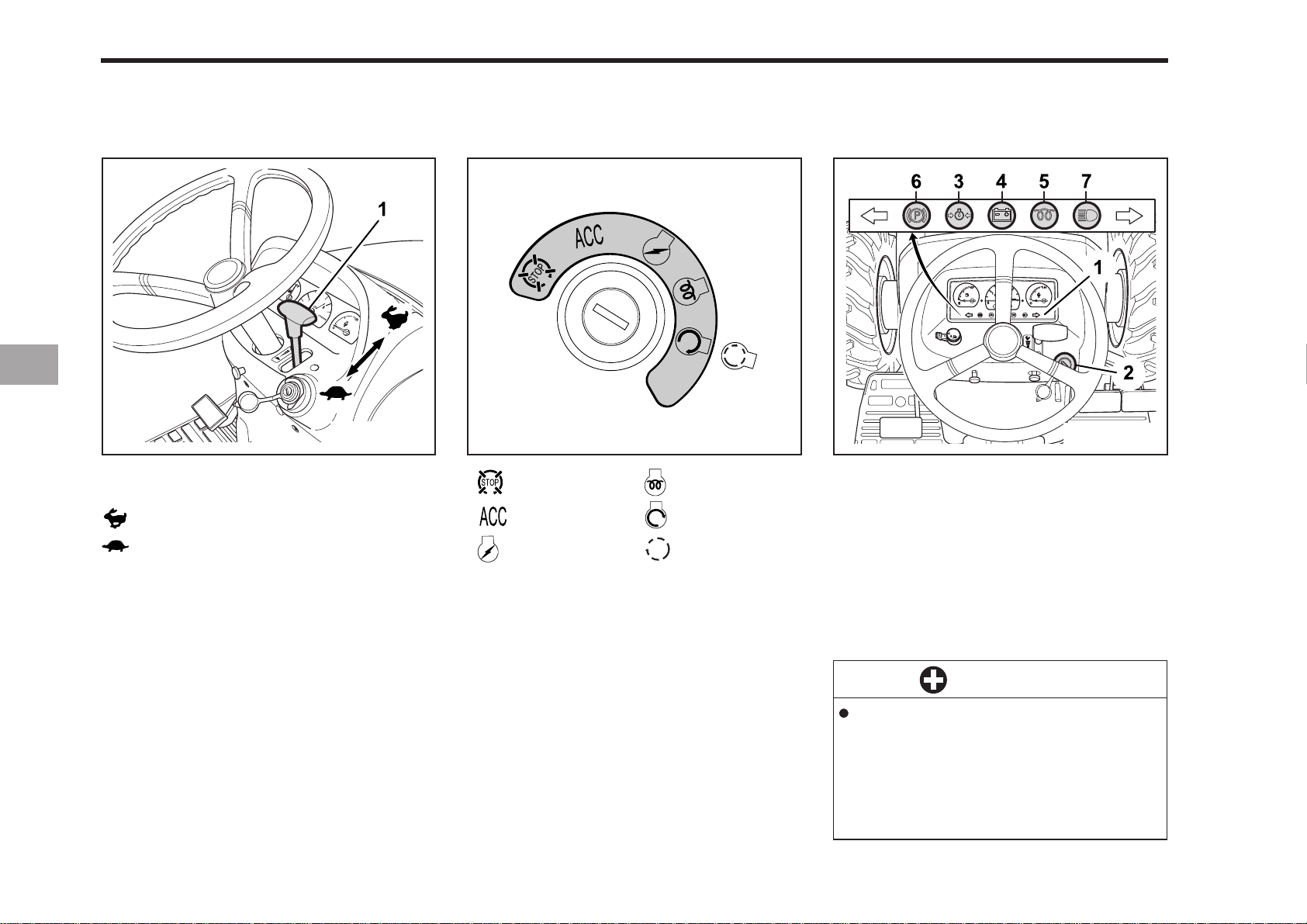
(1) Easy Checker (5) Glow Plug Indicator
(2) Key Switch (6) Parking Brake
(3) Engine Oil Pressure (7) High Light
(4) Electrical Charge
CHECK EASY CHECKER LAMPS:
1. When the key is turned “ON”, lamps
(3), (4) should come on. If trouble
should occur at any location while the
engine is running, the warning lamp
corresponding to that location comes on.
2. Glow plug indicator (5) also comes on
when the key is turned “ON” to preheat the engine and goes off automatically when preheat is completed.
3. The parking brake warning lamp (6)
comes on while parking brake is applied and goes off when it is released.
IMPORTANT
Daily checks with the Easy Check
only, are not sufficient. Never fail
to conduct daily checks carefully
by referring to Daily Check. (See
“DAILY CHECK” in Periodic Service Section)
Page 43
OPERATING THE ENGINE 6-5
TURN THE KEY TO “PREHEAT”
POSITION AND HOLD IT FOR
ABOUT 9 SECONDS.
NOTE
Glow plug indicator (5) comes on
while engine is being preheated.
TURN THE KEY T O “ST AR T”
POSITION AND RELEASE WHEN
THE ENGINE ST ARTS.
IMPORTANT
The engine will not start unless
the range gear shift lever (Hi-Lo)
and the P.T.O clutch lever are in
the “OFF” position.
CHECK TO SEE THAT ALL THE
LAMPS ON THE EASY CHECKER
ARE “OFF”.
If the lamp is still on, immediately stop the
engine and determine the cause.
Page 44
6-6 CK20
STOPPING THE ENGINE
196O607A
1. You must first slow the engine to the
idle position before turning the engine
off.
2. Remove the key.
W ARMING UP
CAUTION
During warm up of the engine be
sure that the parking brake is set.
After starting your tractors engine allow
five minute warm up before applying any
load to the tractor. This will allow time
for oil to reach every part of the engine.
If a load is applied to the tractor before it
has time to warm up then serious damage can occur like, premature wear,
breakage, or seizure.
WARM-UP AND TRANSMISSION OIL
IN THE LOW TEMPERATURE RANGE
z Hydraulic oil serves as transmission
fluid. In cold weather, the oil may be
cold with increased viscosity. This can
cause delayed oil circulation or abnormally low hydraulic pressure for some
time after engine start-up. This in turn
can result in trouble in the hydraulic
system. To prevent the above, observe
the following instructions:
z Warm up the engine at about 50 % of
rated rpm according to the table
below:
Ambient
temperature
Above 0 °C
(32 °F)
0 ~ -10 °C
(32 ~ 14 °F)
-10 ~ -20 °C
(14 ~ -4 °F)
Warm-up time
requirement
At least 5 minutes
5 ~ 10 minutes
10 ~ 15 minutes
Below -20 °C
(-4 °F)
More than 15
minutes
IMPORTANT
Do not operate the tractor under
full load condition until it is sufficiently warmed up.
Page 45
JUMP ST ARTING
OPERATING THE ENGINE 6-7
CAUTION
To avoid personal injury:
Keep all flames, sparks, and cigarettes away from the battery.
If the tractors battery is frozen,
do not jump start the engine.
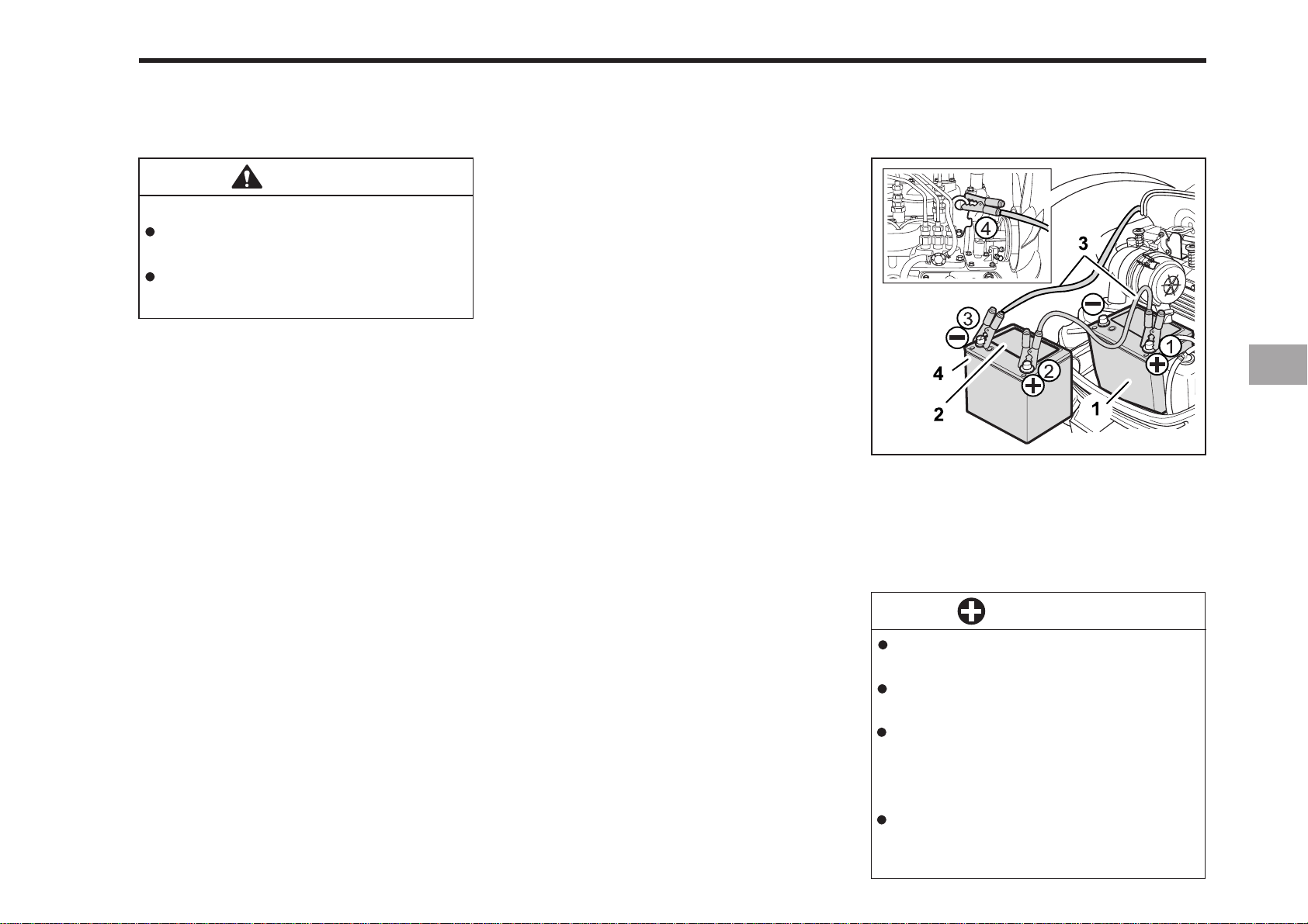
When jump starting the engine, follow the
instructions below to safely start the
engine.
1. Use a battery of the same voltage as
the disabled tractor to jump start the
tractor. Make sure the battery is within
a safe distance to the tractor so that
the jumper cables can reach.
2. Engage the parking brake of the tractor and shut the tractor off.
3. Put on safety goggles and rubber
gloves.
4. Make sure that the battery vent caps
are securely in place.
5. Cover the vent hole with damp rags,
and do not allow the rags to touch the
battery terminals.
6. Attach the red clamp to the positive
terminal of the dead battery, and attach the other end to the positive cable
of the helper battery.
7. Clamp the black cable to the negative
terminal of the dead battery, and attach the other end to the negative
cable of the engine hook.
8. If the helper battery is in a vehicle,
start the vehicles engine and let it run
for a few moments. Then start the
disabled tractor.
9. Disconnect the battery cables in the
exact opposite order as they were
attached
10. Remove the damp rags and reinstall
the vent caps.
196O608A
Connect cables in numerical order. Disconnect
in reverse order after use.
(1) Dead Battery
(2) Lay a Damp Rag Over the Vent Caps
(3) Jumper Cables (4) Helper Battery
IMPORTANT
This tractor has a 12 volt negative ground starting system.
Use only the same voltage for
jump starting the tractor.
The use of a higher voltage system for jump starting can cause
severe damage to the tractors
electrical system.
Use only a matching voltage
source when “Jump Starting” a
dead battery.
Page 46

Page 47

OPERATING NEW TRACTOR
OPERATING FOLDABLE ROPS
STARTING
STOPPING
7OPERATING THE TRACTOR
CHECK DURING DRIVING
PARKING
OPERAING TECHNIQUES
P.T.O OPERATION
Page 48

7-2 CK20
OPERA TING NEW TRACTOR
How a new tractor is handled and maintained determines the life of the tractor.
A new tractor just off the factory production line has been, of course, tested,
but the various parts are not accustomed
to each other, so care should be taken to
operate the tractor for the first 50 hours
at a slower speed and avoid excessive
work or operation until the various parts
become “broken-in.”. The manner in
which the tractor is handled during the
“breaking-in.” period greatly affects the
life of your tractor. Therefore, to obtain
the maximum performance and the longest life of the tractor, it is very important
to properly break-in your tractor.
In handling a new tractor, the following
precautions should be observed.
z You should not operate your tractor at
full speed for the first fifty hours of
use.
z Do not start your tractor abruptly or
apply the brakes suddenly.
z In cold climates, allow your tractor
plenty of time to warm up.
z Do not run the engine at speeds faster
than necessary.
z Use due caution when operating your
tractor on rough roads or terrain.
The above precautions are not limited to
new tractors only, but are a good practice for tractors regardless of their age.
CHANGING LUBRICA TING OIL
FOR NEW TRACTORS
Special attention should be given to new
tractors lubrication oil. New parts are not
accustomed to each other and are not
broken in properly. Small metal grit can
develop in the lubricating system as metal
parts begin to “break in”, and continuous
use of the contaminated oil can cause
damage and failure.
Therefore you should change the
tractor’s oil before you normally would.
For further details of the oil change and
service schedule, see “maintenance”
section.
Page 49
OPERATING ROPS
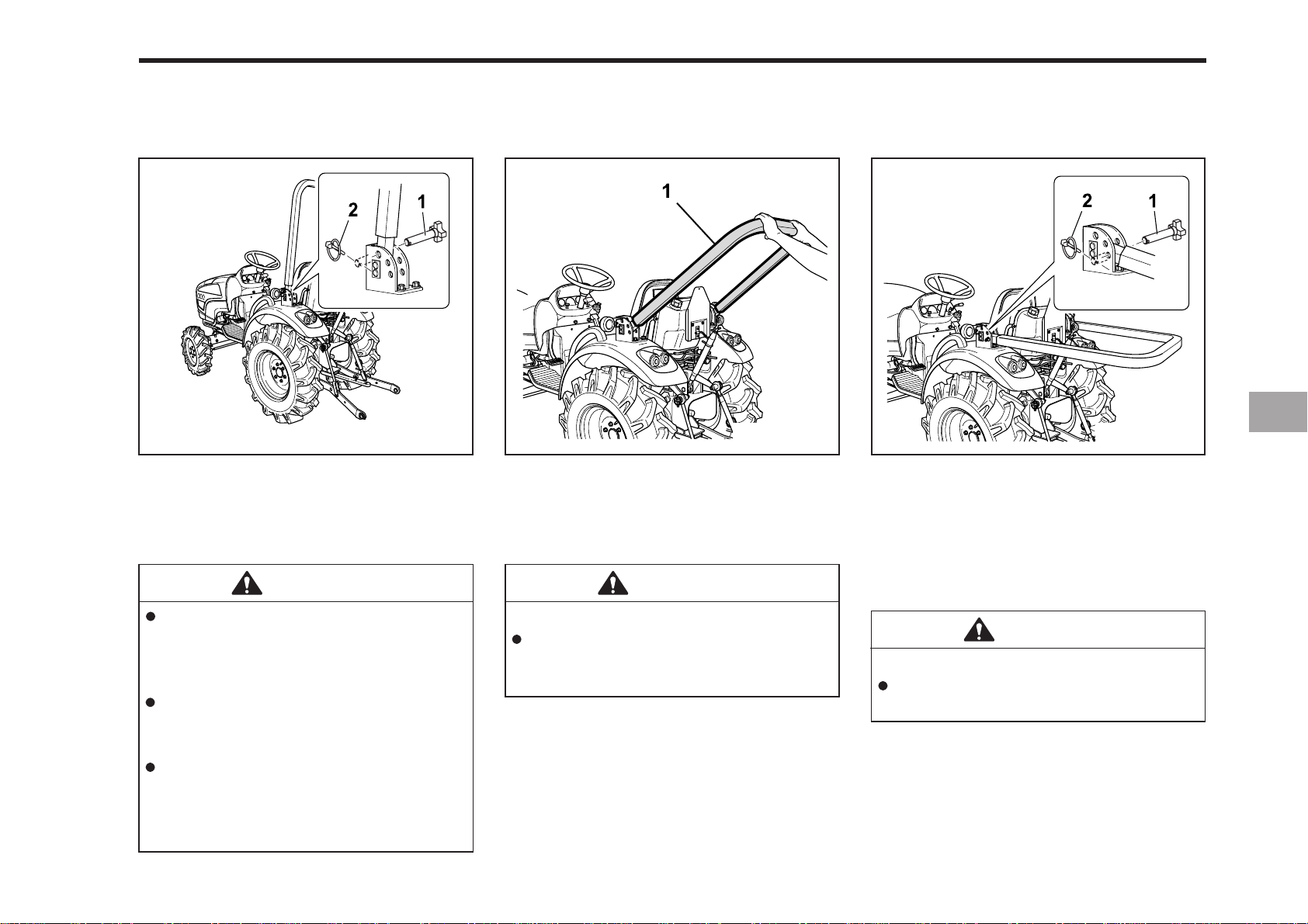
TO FOLD THE ROPS
OPERATING THE TRACTOR 7-3
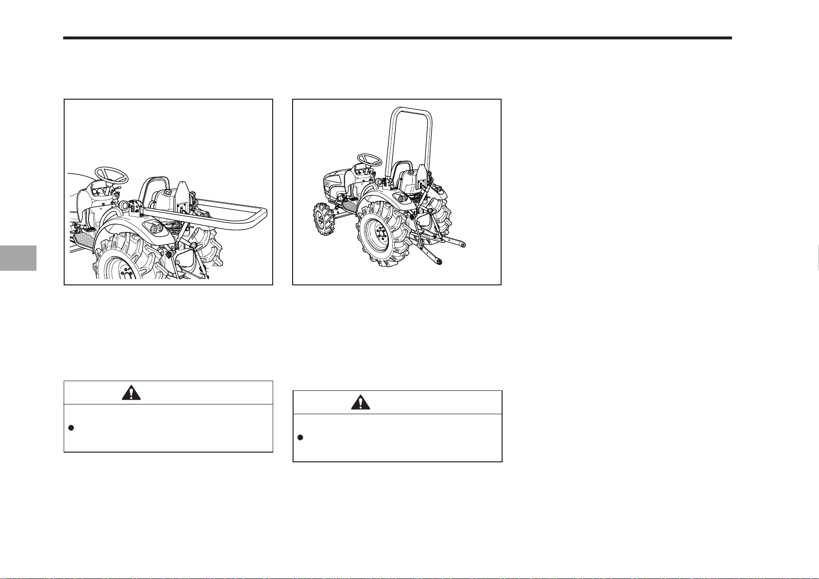
(1) Bolt
(2) Nut
(1) ROPS
1. Remove the nut and bolt. 2. Fold the ROPS.
CAUTION
You should always stop the
engine, remove the key and set
the parking brake before raising
or folding the rops.
Always perform such tasks from
a safe and stable position at the
rear of the tractor.
Folding the ROPS should only be
done when absolutely necessary,
and should be returned to the upright position as soon as possible.
To avoid personal injury:
Hold the ROPS tightly with both
hands and fold the ROPS slowly
and carefully.
CAUTION
196O702A196O701A
(1) Bolt
(2) Nut
196O703A
3. Align bolt holes, insert both bolt, and
secure them with the nut.
CAUTION
To avoid personal injury:
Make sure the bolt are properly
installed and secured.
Page 50
7-4 CK20
TO RAISE THE ROPS TO
UPRIGHT POSITION
196O705A196O704A
(1) Bolt
(2) Nut
1. Remove both the nut and bolt.
2. Raise ROPS to the upright position.
CAUTION
To avoid personal injury:
The ROPS must be raise slowly
and carefully.
(1) Bolt
(2) Nut
3. Align bolt holes, insert both bolt and
secure them with the nut.
CAUTION
To avoid personal injury:
Make sure that both bolt and nut
are properly installed.
Page 51
STARTING
OPERATING THE TRACTOR 7-5
ADJUSTING THE OPERA TOR’S
POSITION
196O707A
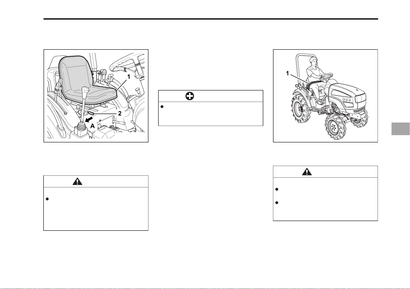
(1) Seat (A) “PULL OUT”
(2) Position Adjust Lever
OPERA TOR’S SEAT
SEA T BELT
TRA VEL ADJUSTMENT
Pull out the position adjust lever and slide
the seat backward or forward, as
required. The seat will lock in position
when the lever is released.
IMPORTANT
After adjusting the operator’s
seat, be sure to check that the
seat is properly locked.
196O708A
(1) Seat Belt
CAUTION
CAUTION
To avoid personal injury:
Make sure that the seat is completely secured after each
adjustment.
Do not allow any person other than
the driver to ride on the tractor.
To avoid personal injury:
Always use your seat belt when
the ROPS is installed.
Do not use the seat belt if your
tractor is not equipped with a
ROPS or when it is removed.
Adjust the seat belt for proper fit and
connect to the buckle. The seat belt is
auto-locking retractable type.
Page 52
7-6 CK20
SELECTING LIGHT SWITCH
POSITIONS
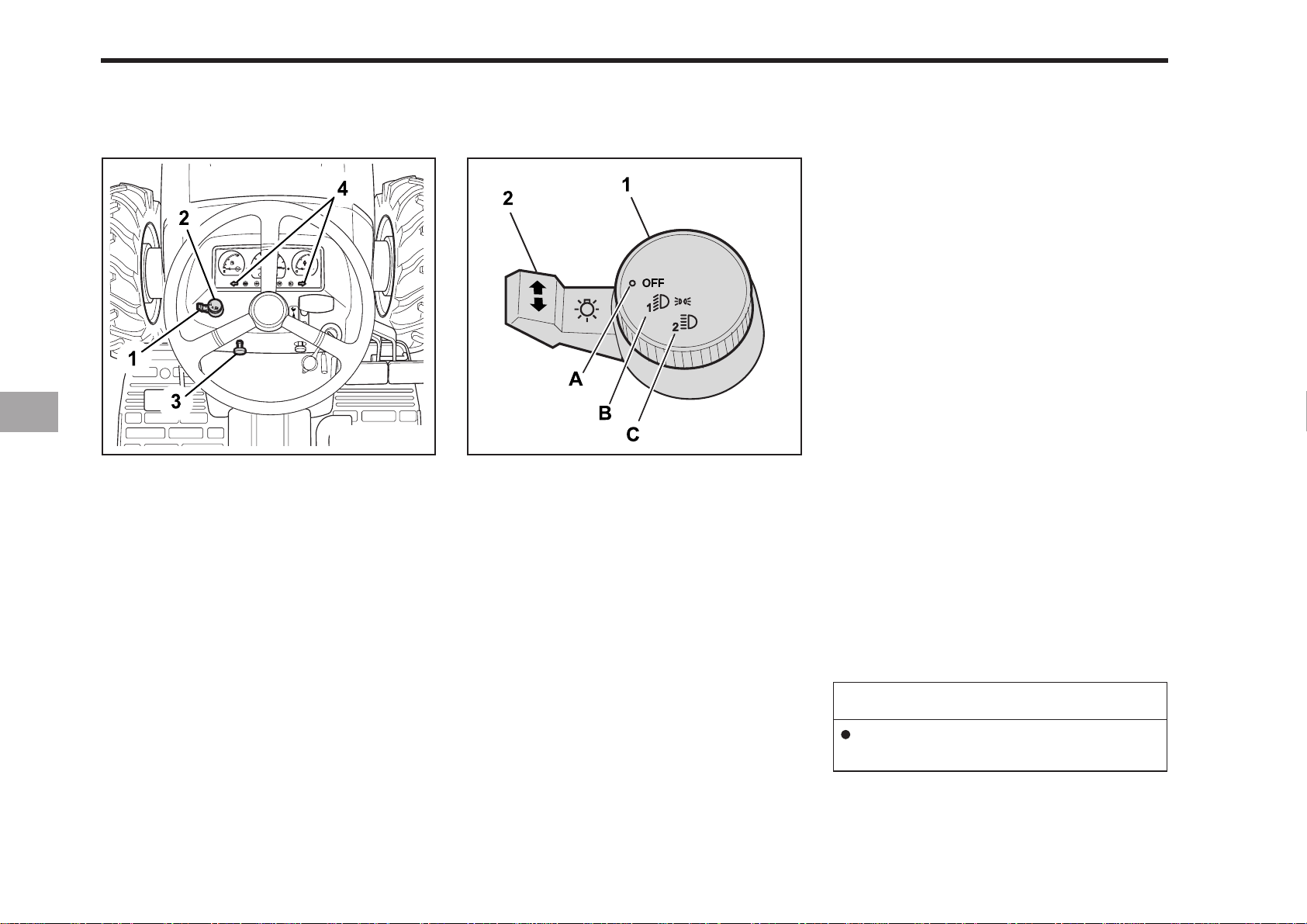
HEAD LIGHT SWITCH
(A): Head lights OFF.
(B): Head lights - Low Beam ON.
(C): Head lights - High Beam ON.
HAZARD LIGHT SWITCH
When hazard light switch is pulled up
backward, the hazard lights flash along
with the indicator on the instrument panel.
Push the switch down forward to turn
off the light.
196O710A196O709A
(1) Turn Signal Light Switch
(2) Head Light Switch
(3) Hazard Light Switch
(4) Hazard / Turn Signal Indicator
(1) Head Light Switch
(2) Turn Signal Light Switch
(A) “OFF”
(B) “ON (LOW)”
(C) “ON (HIGH)”
TURN SIGNAL LIGHT SWITCH
To indicate a right turn, push down forward.
To indicate a left turn, push down backward.
When the left or right turn signal is acti-
vated in combination without the hazard
lights, the indicated turning light will flash
and the other will be off.
NOTE
Be sure to return switch to center position after turning.
Page 53
CHECKING THE BRAKE PEDAL
OPERATING THE TRACTOR 7-7
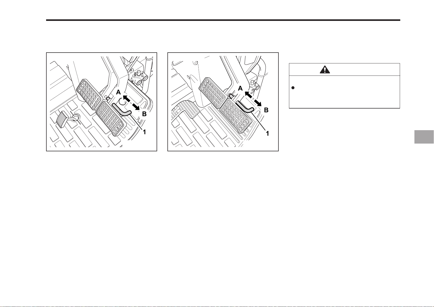
CK20
(1) Brake Pedal Lock
(A) Lock (B) RELEASE
CK20H
(1) Brake Pedal Lock
(A) Lock (B) RELEASE
BRAKE PEDAL (RIGHT AND LEFT)
WARNING
To avoid personal injury:
Applying one rear wheel brake at
a time can cause the tractor to
swerve or roll over at high speeds.
1. Before operating the tractor on the
road or before applying the parking
brake, be sure to interlock the right
and left pedals as illustrated below.
196O712A196O71 1A
2. Use individual brakes to assist in making sharp turns at slow speeds (Field
Operation Only).
Disengage the brake pedal lock and
depress only one brake pedal.
3. Be sure brake pedals have equal adjustment when using locked together.
Page 54
7-8 CK20
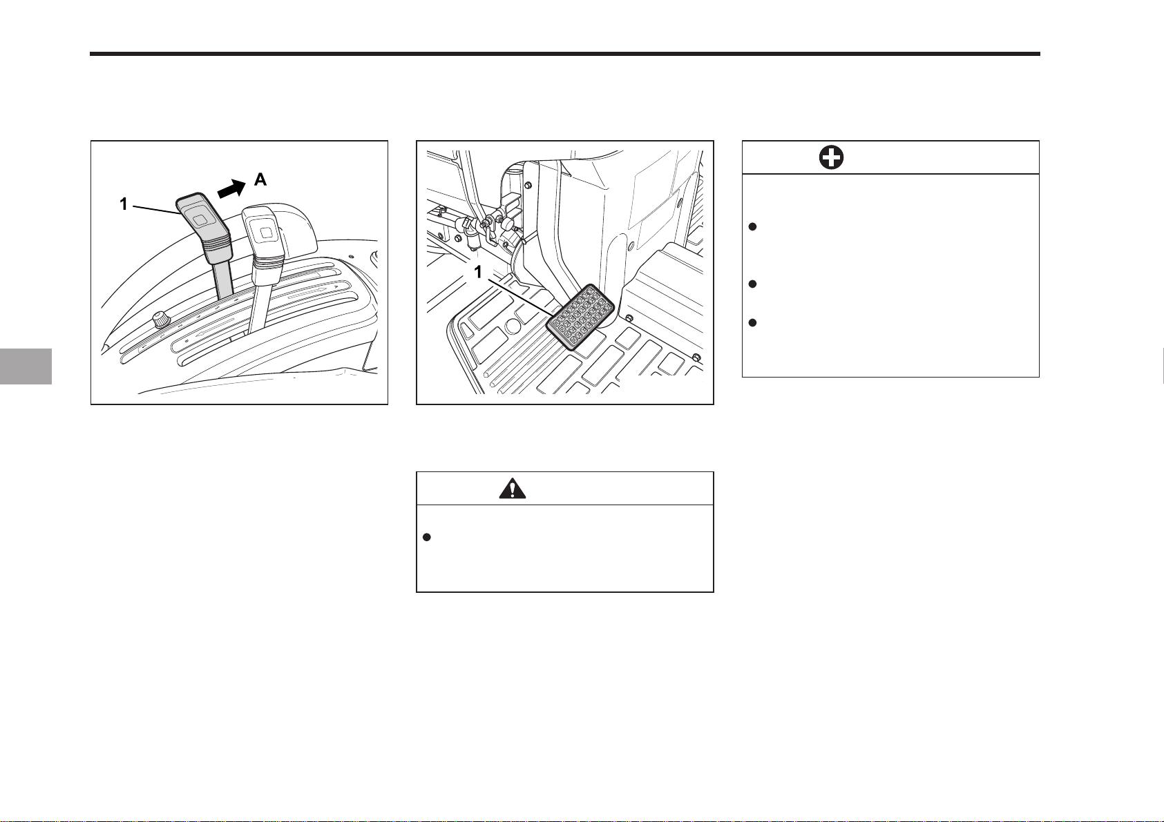
RAISE THE IMPLEMENT (SEE
“HYDRAULIC UNIT” SECTION)
(A) UP
DEPRESS THE CLUTCH PEDAL
IMPORTANT
To help prevent premature clutch
wear.
The clutch pedal must be engaged slowly and disengaged
quickly.
Do not rest your foot on the clutch
pedal.
Select the proper gear and engine
speeds according to the type of
job you are doing.
196O714A196O713A
(1) Clutch Pedal(1) Position Control Lever
CAUTION
To avoid personal injury:
Do not release the clutch suddenly,
it may cause the tractor to lunge
forward unexpectedly.
The clutch is disengaged when the clutch
pedal is fully pressed down.
Page 55
SELECTING THE TRAVEL SPEED.
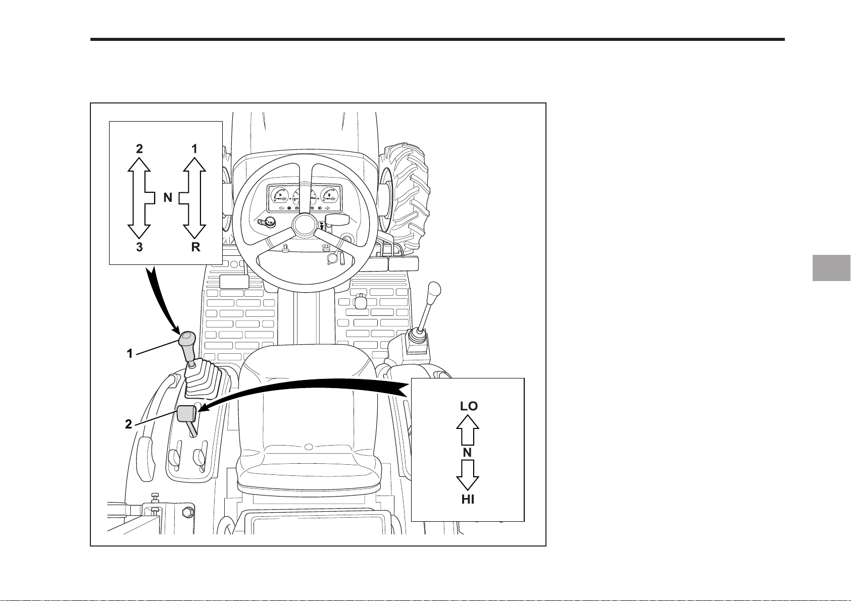
OPERATING THE TRACTOR 7-9
CK20
(1) Main Gear Shift Lever
(2) Range Gear Shift Lever (Hi-Lo)
(N) NEUTRAL POSITION
HI - HIGH
LO - LOW
196O715A
Page 56
7-10 CK20
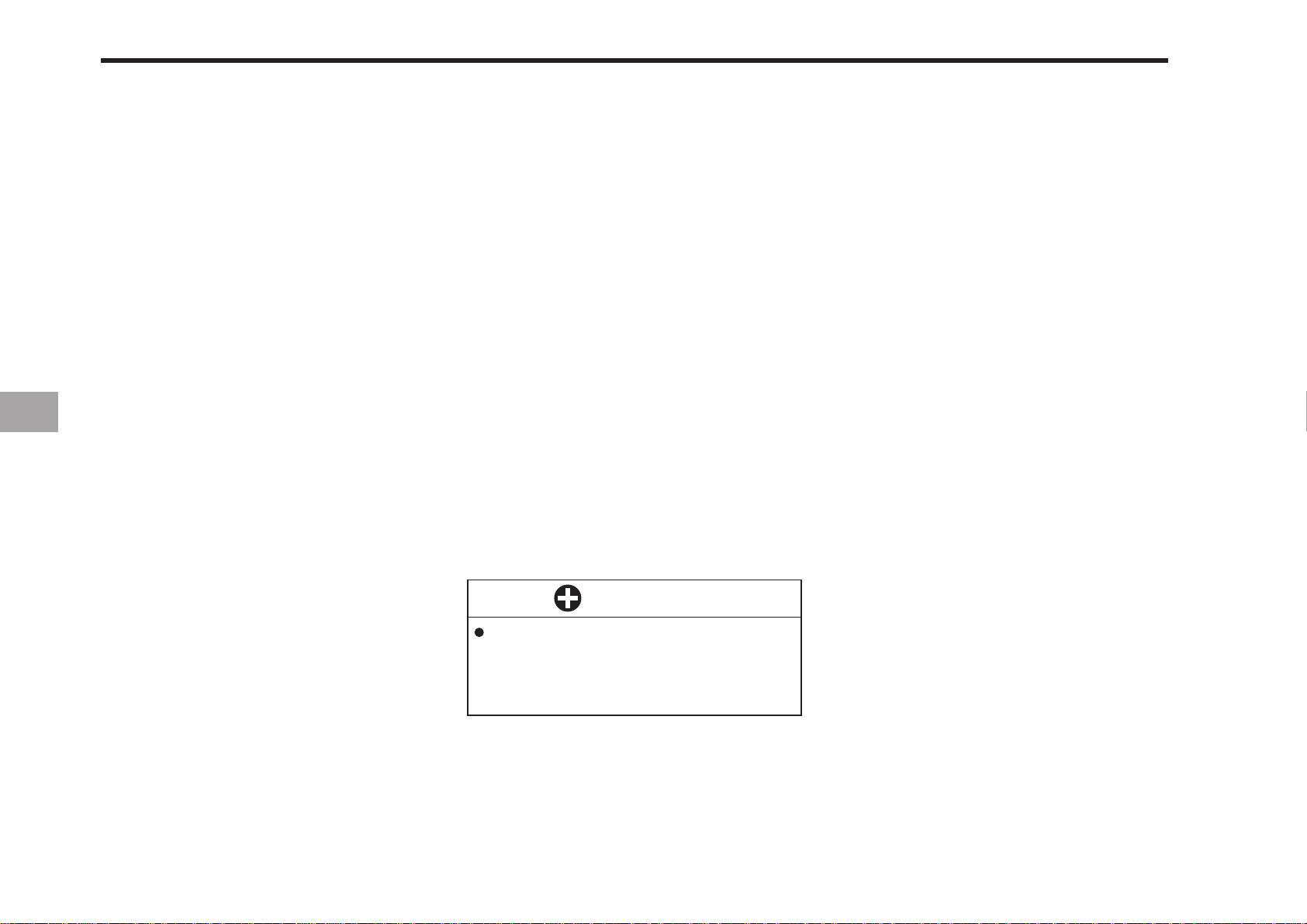
MAIN GEAR SHIFT LEVER
The main shift uses a syncro-mesh and
a constant mesh.
Rotary power which is transmitted from
engine to gear shaft via the clutch is
changed in three ways by operating the
main shift lever to shift the shifters, and
transmits to the counter shaft.
RANGE GEAR SHIFT LEVER (HI-LO)
The range gear shift can only be shifted
when tractor is completely stopped and
clutch is depressed.
If it is difficult to shift the range gear,
take the following actions.
1. Be sure the range gear shift lever is in
neutral position.
2. Release clutch pedal.
3. Slightly depress the speed control
pedal to rotate the gears inside of
transmission.
4. Release the speed control pedal to
neutral.
5. Depress clutch pedal and then shift
the range gear shift lever.
IMPORTANT
To avoid transmission damage,
depress clutch pedal and stop
tractor before shifting between
ranges.
Page 57
OPERATING THE TRACTOR 7-11
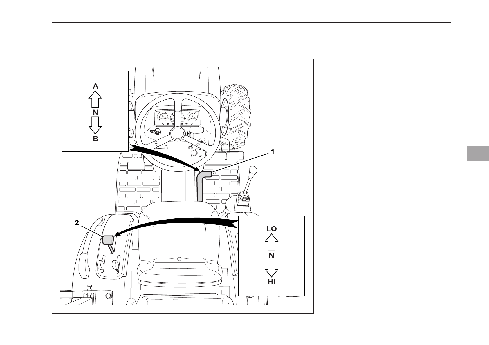
CK20H
(1) Speed Control Pedal
(2) Range Gear Shift Lever (Hi-Lo)
(A) FORWARD
(B) REVERSE
(N) NEUTRAL POSITION
HI - HIGH
LO - LOW
196O716A
Page 58
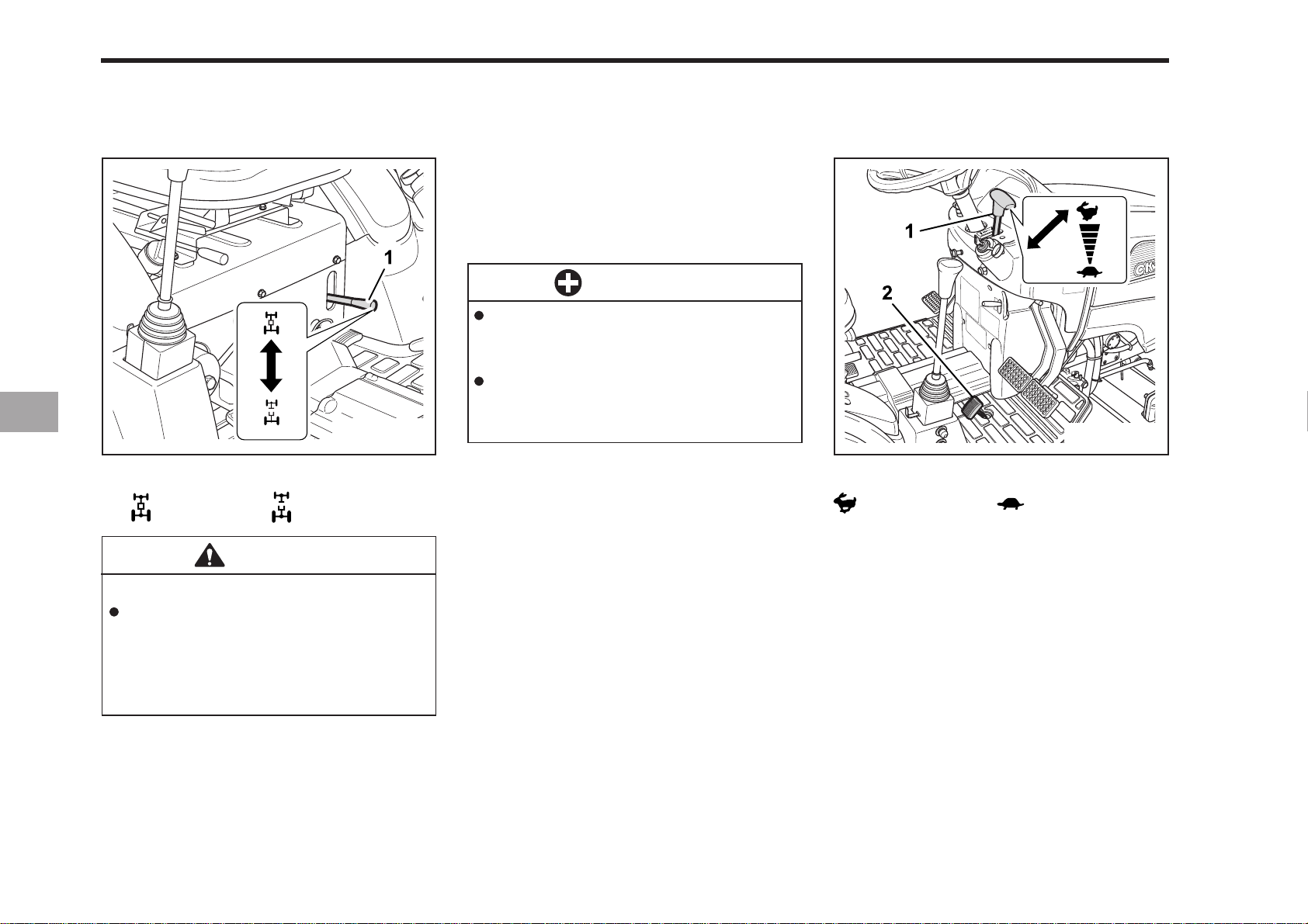
7-12 CK20
FRONT WHEEL DRIVE LEVER
(1) Front Wheel Drive Lever
O N OFF
CAUTION
To avoid personal injury:
You should not engage your front
wheel drive while traveling at
road speeds. This can cause your
tractor to stop quickly, and
unexpectedly.
The front wheel drive should always be
engaged when the tractor is stopped.
Shift the lever to the “ON” position to engage the front wheel.
IMPORTANT
Depress the clutch pedal before
engaging the front wheel drive
lever.
Tires will wear quickly if front
wheel drive is engaged on paved
roads.
FRONT WHEEL DRIVE IS EFFECTIVE FOR
THE FOLLOWING JOBS:
1. When greater pulling force is needed,
such as working in a wet field, when
pulling a trailer or when working with
a front-end loader.
2. When working in sandy soil.
3. When working on a hard soil where a
rotary tiller might push the tractor
forward.
ACCELERA TE THE ENGINE
196O718A196O717A
(1) H a nd T hr o t tl e Le v e r (2) Foot Throttle
INCREASE DECREASE
HAND THROTTLE LEVER
Pushing the throttle lever back increases
engine speed, and pulling it forward decreases engine speed.
FOOT THROTTLE
Use the foot throttle when traveling on
the road. Press down on it for higher
speed. The foot throttle is interlocked with
the hand throttle lever; when using the
foot throttle, keep the hand throttle lever
in low idling position.
Page 59
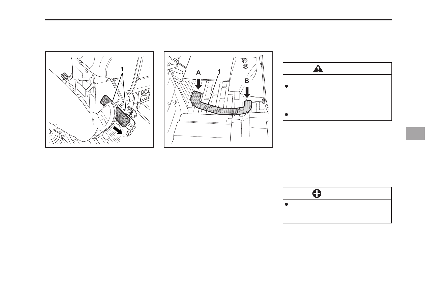
OPERATING THE TRACTOR 7-13
UNLOCK THE P ARKING BRAKE
(1) Brake Pedals
P ARKING BRAKE LEVER
To release the parking brake, simply depress the brake pedals again. Once
released, the parking brake indicator in
the easy checker will go off.
DEPRESS THE SPEED CONTROL
PEDAL (HST TYPE)
196O720A196O719A
(1) Speed Control Pedal
(A) FORWARD (B) REVERSE
SPEED CONTROL PEDAL
WARNING
To avoid personal injury:
If your tractor moves while on level
ground with your foot of the control pedal, do not operate the
tractor.
Consult your KIOTI dealer.
FORW ARD PEDAL
Depress the control pedal with the toe of
your right foot to move forward.
REVERSE PEDAL
Depress the pedal with the heel of your
right foot to move backward.
IMPORTANT
To prevent serious damage to the
HST do not adjust the stopper
bolts.
Page 60
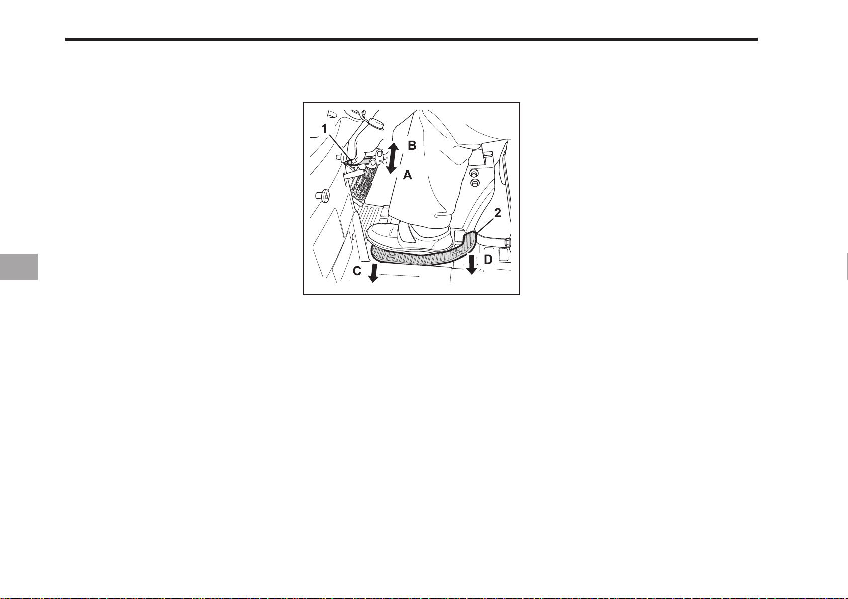
7-14 CK20
LIVE P.T.O(CK20H)
“Live” P.T.O operation can be obtained
with HST transmission tractor. Depress
clutch and move P.T.O gear shift lever to
“ON” position. Release the clutch end the
P.T.O will be engaged. Forward or Reverse movement can now be obtained
with the speed control pedal. To stop the
tractor movement without disengaging
P.T.O, step out the foot from speed control pedal and set parking brake.
The P.T.O continues running even if you
change the traveling speed or stop the
tractor.
Before dismounting tractor, shift the
range gear shift ever (Hi-Lo) to the neutral position and set parking brake.
(1) Speed Set Lever
(2) Speed Control Pedal
(A) ON (C) Increase
(B) OFF (D) Decrease
196O721A
SPEED SET DEVICE
The Speed Set Device is designed for
tractor operating efficiency and operator comfort. This device will provide a
constant forward operating speed by
mechanically holding the speed control
pedal at the selected position.
To Engage Speed Set Device
1. Accelerate speed to desired level using Speed Control Pedal, and push the
speed set lever down to the “ON”
position.
2. Release Speed Control Pedal and desired speed will be maintained.
To Disengage Speed Set Device
1. Place the lever to the off position.
Page 61

OPERATING THE TRACTOR 7-15
NOTE
If you step on the pedal on the forward travel side, the speed set device will disengage.
Make sure to keep the speed set lever
in the off position when starting the
tractor.
Return the speed set lever to the off
position when stopping the tractor.
Speed set device will not operate in
reverse.
The speed control lever can be released When overloads or any sudden forces are obtained.
STOPPING
1. Slow the engine to an idle
2. Depress the clutch and brake pedal
3. After the tractor has stopped, disengage the P.T.O, lower the implement,
shift the transmission into neutral, release the clutch pedal and set the parking brake.
HORN(only EU)
196O737A
(1) Horn Switch
(2) Horn
IMPORTANT
To prevent the damage of speed
set device, do not depress the
reverse travel side pedal when
the speed set device is engaged.
CAUTION
To avoid personal injury and maintain optimum control of tractor,
do not use the speed set device
at high speeds or when roading
the tractor.
Page 62
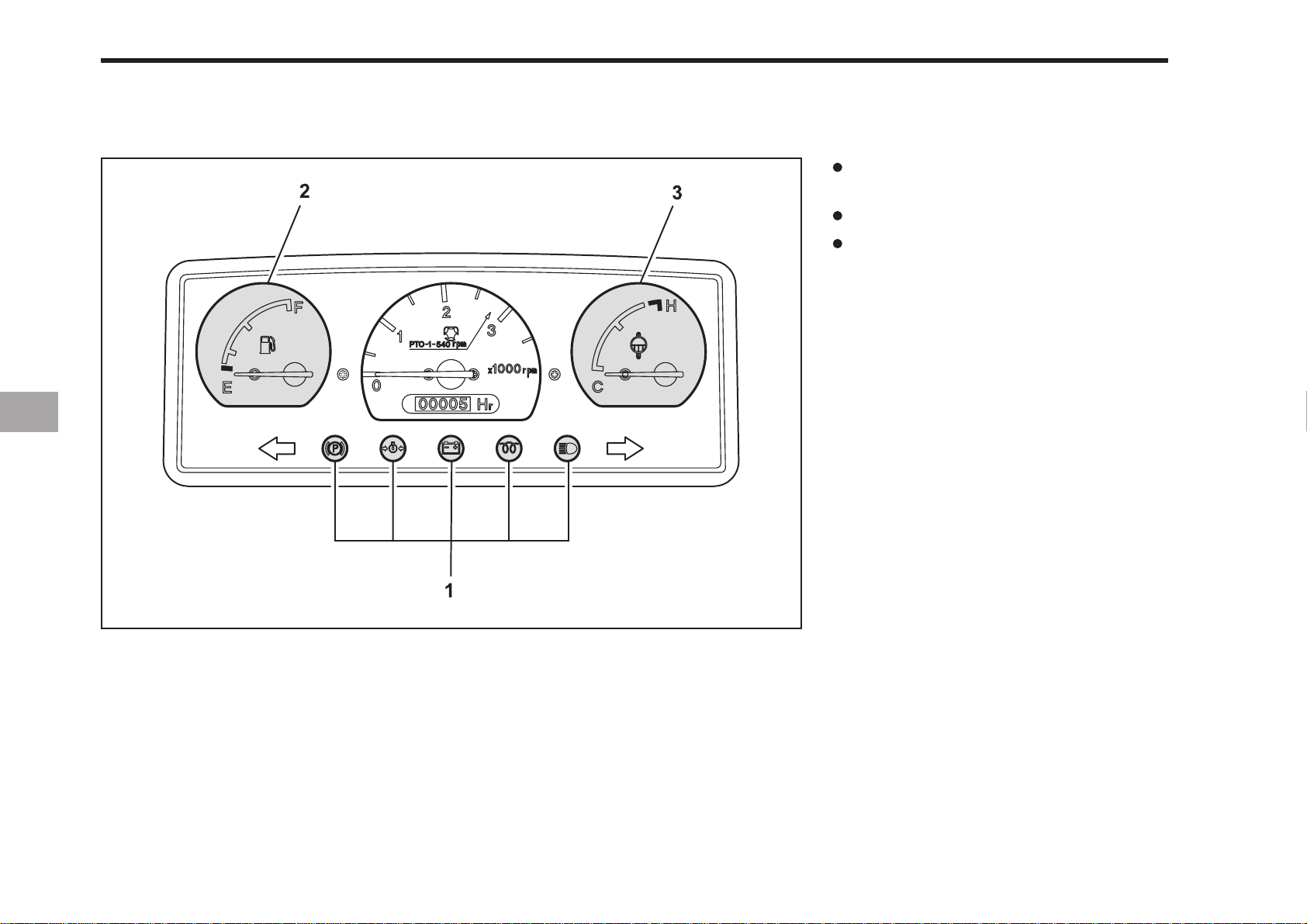
7-16 CK20
CHECK DURING DRIVING
IMMEDIA TEL Y STOP THE ENGINE IF
The engine suddenly slows or
accelerates.
Unusual noises are heard.
Exhaust fumes become dark.
While driving make the previous checks
to ensure that all parts are functioning
properly.
(1) Easy Checker
(2) Fuel Gauge
196O722A
(3) Coolant T emperature Gauge
Page 63
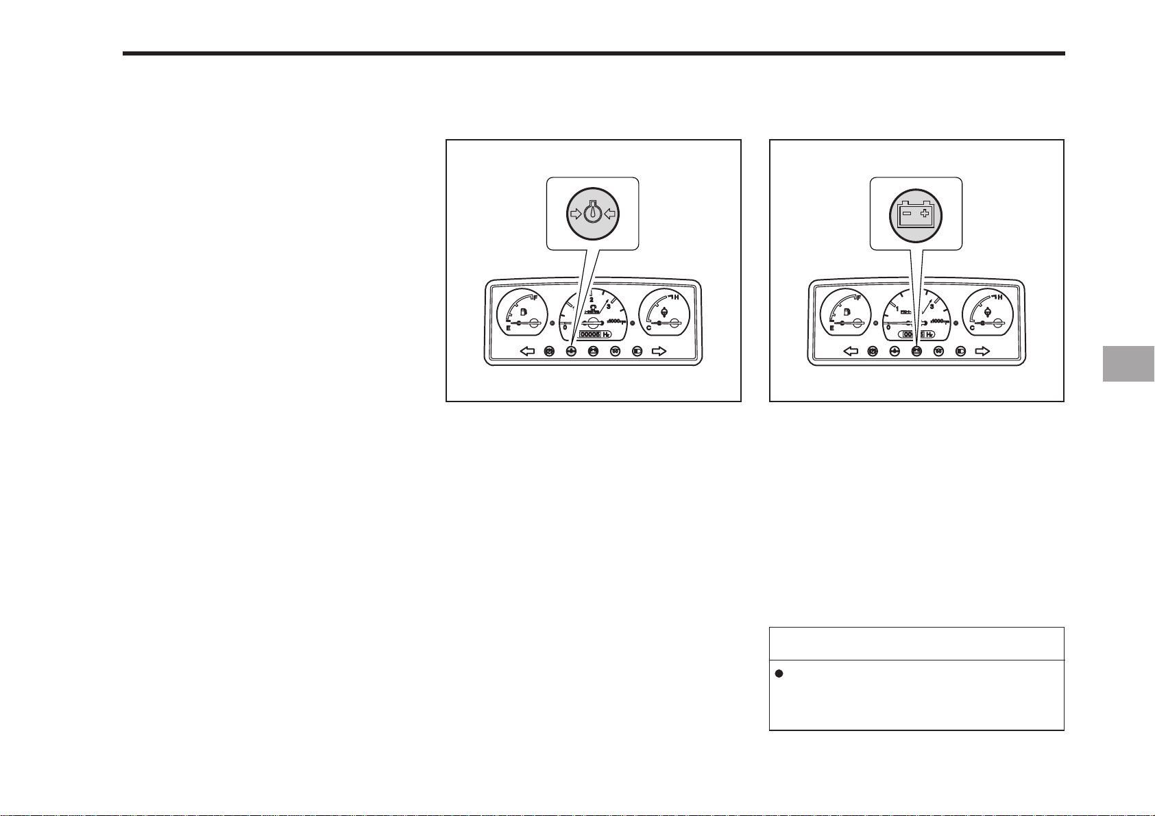
EASY CHECKER
If warning lamps come on while operating the engine, immediately stop the engine and check for the cause.
Never operate the tractor while warning
lamps are on.
OPERATING THE TRACTOR 7-17
196O723A
ENGINE OIL PRESSURE INDICA TOR
When the oil pressure in the tractors engine falls below the prescribed level, the
warning lamp will illuminate.
If this should happen during tractor operation and it does not go off when the
engine is accelerated above 1,000 rpm,
check the engine oil level.
196O724A
ELECTRICAL CHARGE INDICA T OR
If the alternator is not charging the battery,
the warning lamp in the Easy Checker
will come on.
If this should happen during operation,
check the electrical charging system or
consult your local KIOTI dealer.
NOTE
For checking and servicing of your
tractor, consult your local KIOTI
dealer for instructions.
Page 64
7-18 CK20
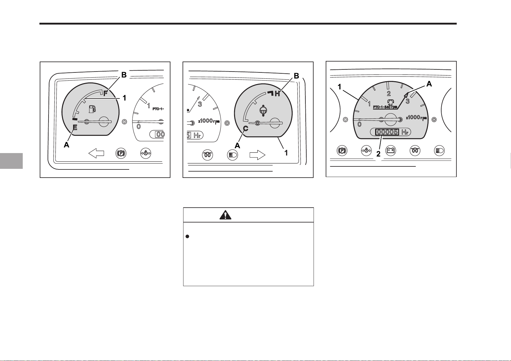
FUEL GAUGE
(1) Fuel Gauge
(A) EMPTY (B) FULL
When the key switch is on, the fuel gauge
indicates the fuel level.
Be careful not to empty the fuel tank. Otherwise air may enter the fuel system.
Should this happen, the system should
be bled (See “Bleeding Fuel System” in
as required in Periodic Service Section.)
COOLANT TEMPERA TURE GAUGE
196O726A196O725A
(1) Coolant T emperature Gauge
(A) COOL (B) HOT
CAUTION
To avoid personal injury:
Do not remove radiator cap until
coolant temperature is well below its boiling point. Then loosen
cap slightly to the stop to relieve
any pressure before removing
cap completely.
1. When the key switch is turned “ON”
this guage indicates the temperature
of the coolant. “C” is for cold, and “H”
is for hot.
HOURMETER / TACHOMETER
196O727A
(1) T achometer (2) Hour meter
(A) P.T.O: 540 rpm
1. The tachometer indicates the engine
speed and the 540rpm P.T.O shaft
speed location on the dial.
2. The hour-mater indicates, in five digits,
the hours that the tractor has been
operated.
3. Records the hour and portions of the
hours that the tractor has been operated based on an average speed of
2200RPM. Engine speeds below
2200RPM accumulate engine hours at
a slower rate than clock hours.
Engine speeds above 2200RPM accumulate engine hours faster than clock
hours.
Page 65
PARKING
OPERATING THE TRACTOR 7-19
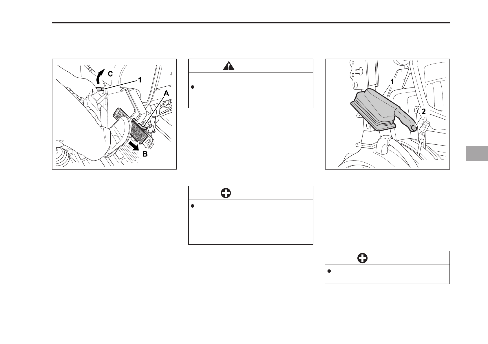
P ARKING BRAKE LEVER
(1) Parking Brake Lever
(A) Interlock the Brake Pedals
(B) DEPRESS (C) PULL
196O728A
CAUTION
To avoid personal injury:
Always set the parking brake and
stop the engine before leaving
the tractor seat.
1. When parking, be sure to set the parking brake.
To set the parking brake;
1) Interlock the brake pedals.
2) Depress the brake pedals.
3) latch the brake pedals with the park-
ing brake lever.
IMPORTANT
To prevent damage to the parking brake lever, make sure that
brake pedals are fully depressed
before pulling the parking brake
lever up.
2. Before getting off the tractor, disengage the P.T.O, lower all implements,
place all control levers in their neutral
positions, set the parking brake, stop
the engine and remove the key.
HANDBRAKE(only EU-CK20)
196O735A
(1) Handbrake
(2) Push button
A conventional handbrake lever(1) is installed to the right of the driver’s seat.
To apply the handbrake, pull the lever up.
To release, ease the lever up further,
depress the button(2) on the end lower
the lever fully.
IMPORTANT
Ensure that the handbrake is fully
released before driving off.
3. If it is necessary to park on an incline,
be sure to chock the wheels to prevent accidental rolling of the machine.
Page 66
7-20 CK20
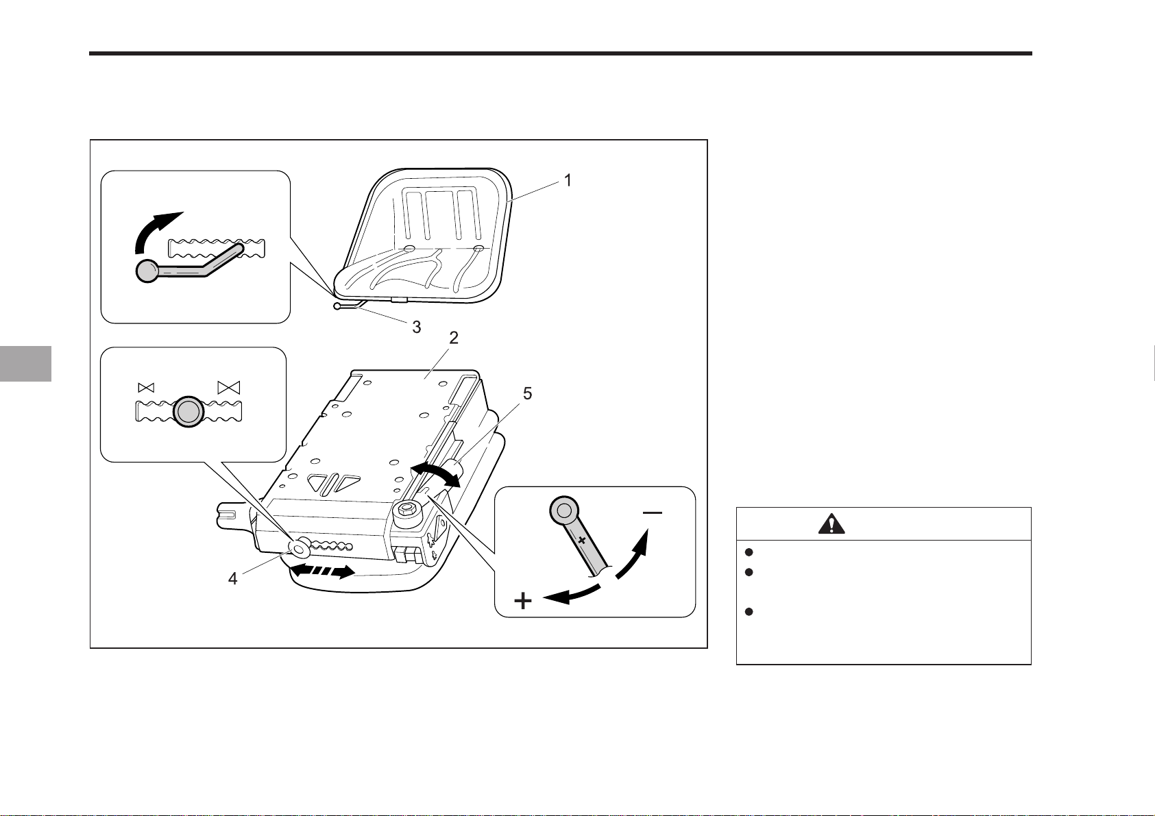
SEA T(only EU)
The seat installed on your tractor has a
comprehensive range of adjustments.
Before prorating the tractor, it is important to adjust the seat to the comfortable
position.
1.The lever which control the seat position (up or down) in accordance with
operator’s. Use the lever when you
change the seat position.
2. When you change the seat position
(front or rear), pull the lever up and
push or pull seat to front or rear
direction.
3. When you change the suspension of
the seat, you can adjust the suspension of the seat using the lever. Pull
the lever front direction and move the
lever left or right.
(1) Seat
(2) Suspension Assembly(XH2)
(3) Horizontal adjustment(Slide rails)
(4) Height adjuster
(5) Weight adjuster
196O736A
CAUTION
For one seated occupant.
Do not adjust seat when vehicle
is in operation.
Keep clear of maintenance should
be carried out by authorized &
competent personnel only.
Page 67
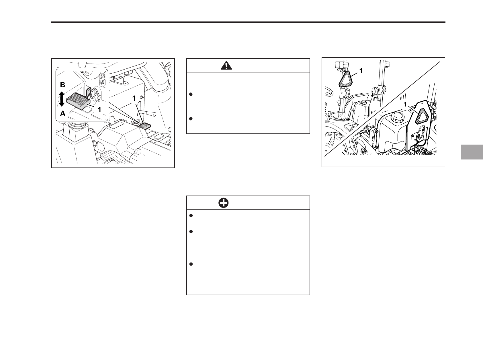
OPERA TING TECHNIQUES
OPERATING THE TRACTOR 7-21
DIFFERENTIAL LOCK
(1) Differential Lock Pedal
(A) Press to “ENGAGE”
(B) Release to “DISENGAGE”
196O729A
W ARNING
To avoid personal injury due to loss
of steering control.
Do not operate the tractor at high
speeds with the differential lock
engaged.
Do not attempt to turn with the
differential lock engaged.
If one of the rear wheels should slip you
should use the differential lock. This will
cause both wheels to turn together. The
differential lock is engaged only when
the pedal is depressed.
IMPORTANT
OPERA TING THE TRACT OR ON A
ROAD
EU
USA
196O730B
(1) SMV
When using the differential lock,
always slow the engine down.
To prevent damage to power train,
do not engage differential lock
when one wheel is spinning and
the other is completely stopped.
If the differential lock cannot be
released in the above manner,
step lightly on the brake pedals
alternately.
Page 68
7-22 CK20
CAUTION
To avoid personal injury:
To help assure straight line stops
when driving at transport speeds,
lock the brake pedals together.
Uneven braking at road speeds
could cause the tractor to rollover.
When traveling on road with 3point hitch mounted implement
attached, be sure to have sufficient front weight on the tractor
to maintain steering ability.
You should make sure that the warning
lamps and SMV sign are clean and visible at all times. If you are towing rear
mounted equipment or implements you will
need to install the warning lamps and SMV
sign on the equipment.
OPERATING ON A SLOPES AND
ROUGH TERRAIN
CAUTION
To avoid personal injury:
Always back up when going up a
steep slope. Driving forward could
cause the tractor to tip over
backward. Stay off hills and slopes
too steep for safe operation.
Avoid changing gears when
climbing or descending a slope.
If operating on a slope, never disengage the clutch or shift levers
to neutral. Doing so could cause
loss of control.
Do not drive the tractor close to
the edges of ditches or banks
which may collapse under the
weight of the tractor. Especially
when the ground is loose or wet.
1. Be sure that the wheels are adjusted
to provide the maximum stability
possible.
DIRECTIONS FOR USE OF
POWER STEERING
1. Power steering is activated only while
the engine is running. Slow engine
speeds make the steering a little
heavier. While the engine is stopped,
the tractor functions in the same manner as tractors without power
steering.
2. When the steering wheel is turned all
the way to the stop, the relief valve is
activated. Do not hold the steering
wheel in this position for a long period
of time.
3. Avoid turning the steering wheel while
the tractor is stopped, or tires may
wear out sooner.
4. The power steering mechanism makes
the steering easier. Be carefuel when
driving on an road at high speeds.
2. You should slow down for rough
roads, slopes, and sharp turns. This
is especially important when you are
transporting heavy equipment on the
rear of the tractor.
3. You should used gears according to
the decent of the slope, and try to avoid
using the brake.
Page 69
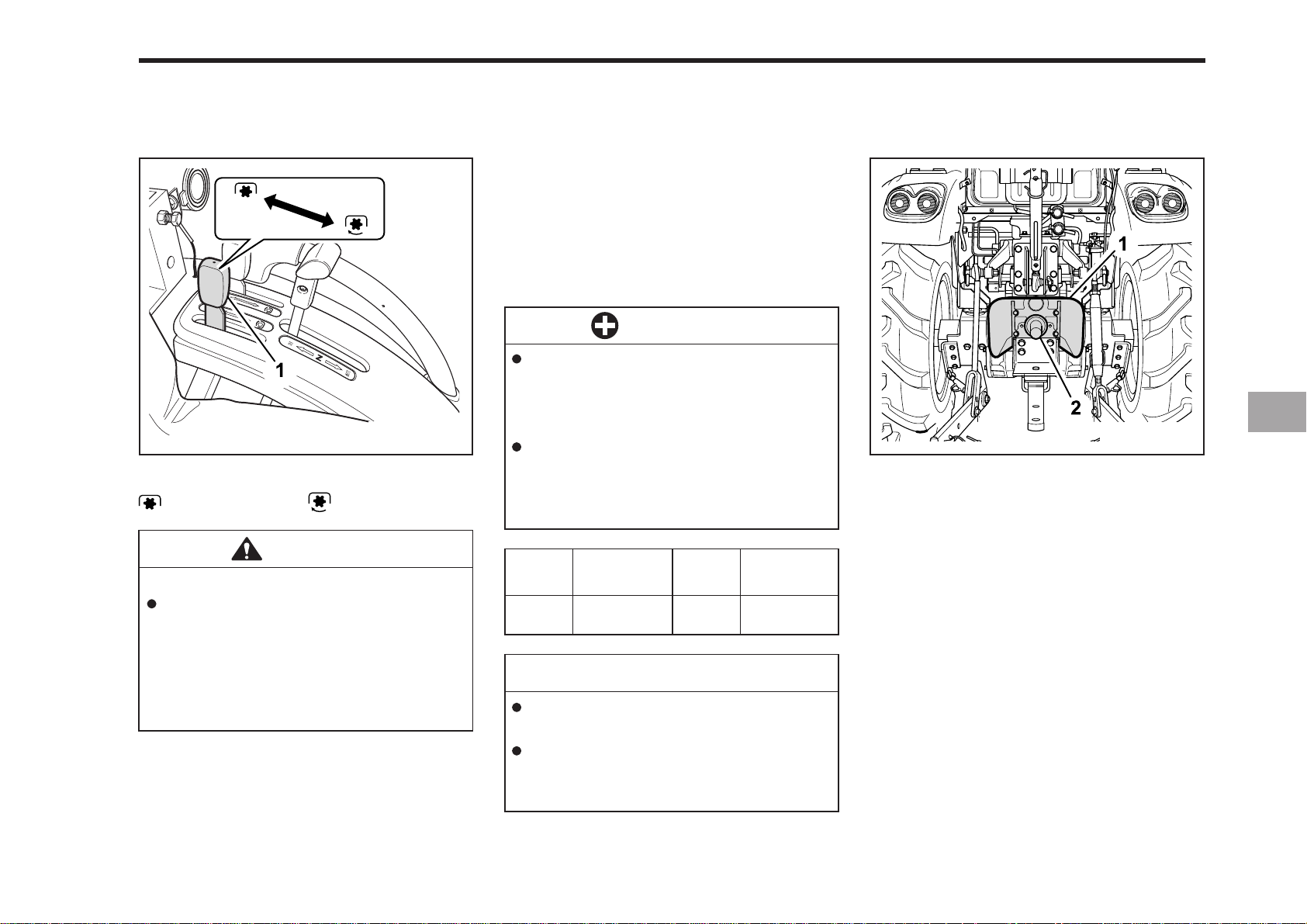
P.T.O OPERATION
OPERATING THE TRACTOR 7-23
P.T.O GEAR SHIFT LEVER
(1) P.T.O Gear Shift Lever
OFF ON
CAUTION
To avoid personal injury:
Disengage P.T.O, stop engine,
and allow all rotating components to come to a complete stop
before connecting, disconnecting,
adjusting, or cleaning any P.T.O
driven equipment.
196O731A
1. The tractor has a 540 rpm speed position.
2. P.T.O shifting needs clutch operation.
Press the clutch pedal down completely
to stop the tractor movement and any P.
T.O driven equipment movement before
shifting the P.T.O gear shift lever.
IMPORTANT
To avoid shock loads to the P.T.O,
reduce engine speed when engaging the P.T.O, then open the throttle
to the recommended speed:
To avoid damage of transmission,
before shifting the P.T.O gear
shift lever, fully disengage the
main clutch.
Model
CK20
CK20H
Engine Speed
min-1 (rpm)
2,646
Shaft
6-Spline
P.T.O Speed
min-1 (rpm)
540
NOTE
There is a P.T.O-1 (540 rpm) indicated
mark on the tachometer board.
Tractor engine will not start if P.T.O
gear shift lever is in the engaged “ON”
position.
P.T.O SHAFT COVER AND SHAFT
CAP
196O734A
(1) P.T.O Shaft Cover (2) P.T.O Shaft Cap
You should keep the P.T.O cover in place
at all times and remember to replace the
cap when the P.T.O shaft is not in use.
Page 70
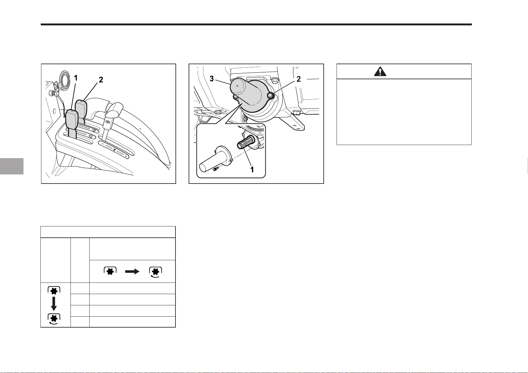
7-24 CK20
MID-P.T.O LEVER MID-P.T.O SHAFT COVER
(1) P.T.O Gear Shift Lever
(2) Mid-P.T.O Lever
REAR AND MID-P.T.O SPEED
P.T.O REVOLUTION [mn
-1
(rpm)]
(1) Mid P.T.O (3) P.T.O Shaft Cover
(2) Bolt
The mid P.T.O is available for KIOTI approved implements.
MID-P.T.O
WARNING
To avoid personal injury:
zz
Before operation, be sure to se-
z
zz
lect the correct P.T.O lever (mid /
rear).
zz
z
Do not operate rear-P.T.O driven
zz
implements and mid-P.T.O driven
implements at the same time.
To use mid-P.T.O, shift the P.T.O gear shift
lever and mid-P.T.O lever to engaged
196O733A196O732A
position. This shifting requires clutch pedal
operation.
MID-
P.T.O
lever
P.T.O
Rear
Mid
Rear
Mid
P.T.O Gear Sift Lever/
P.T.O Clutch control lever
0
0
0
0
540
0
540
2,000
Page 71

THREE-POINT HITCH &
THREE-POINT HITCH & DRAWBAR
3-POINT HITCH
8
DRAWBAR
DRAWBAR
Page 72
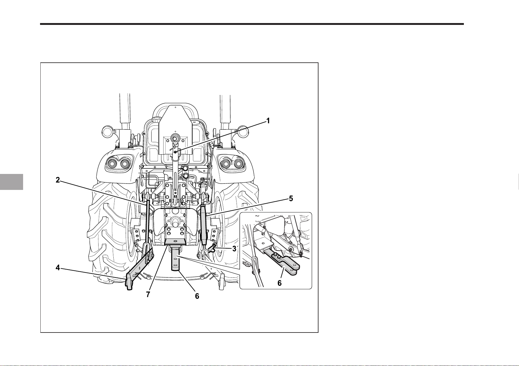
8-2 CK20
THREE-POINT HITCH & DRA WBAR
USA
(1) T op Link
(2) Lifting Rod (Left)
(3) Turnbuckle
(4) Lower Link
(5) Lifting Rod (Right)
(6) Drawbar
(7) Fixed Drawbar Frame
EU
196O801A
Page 73
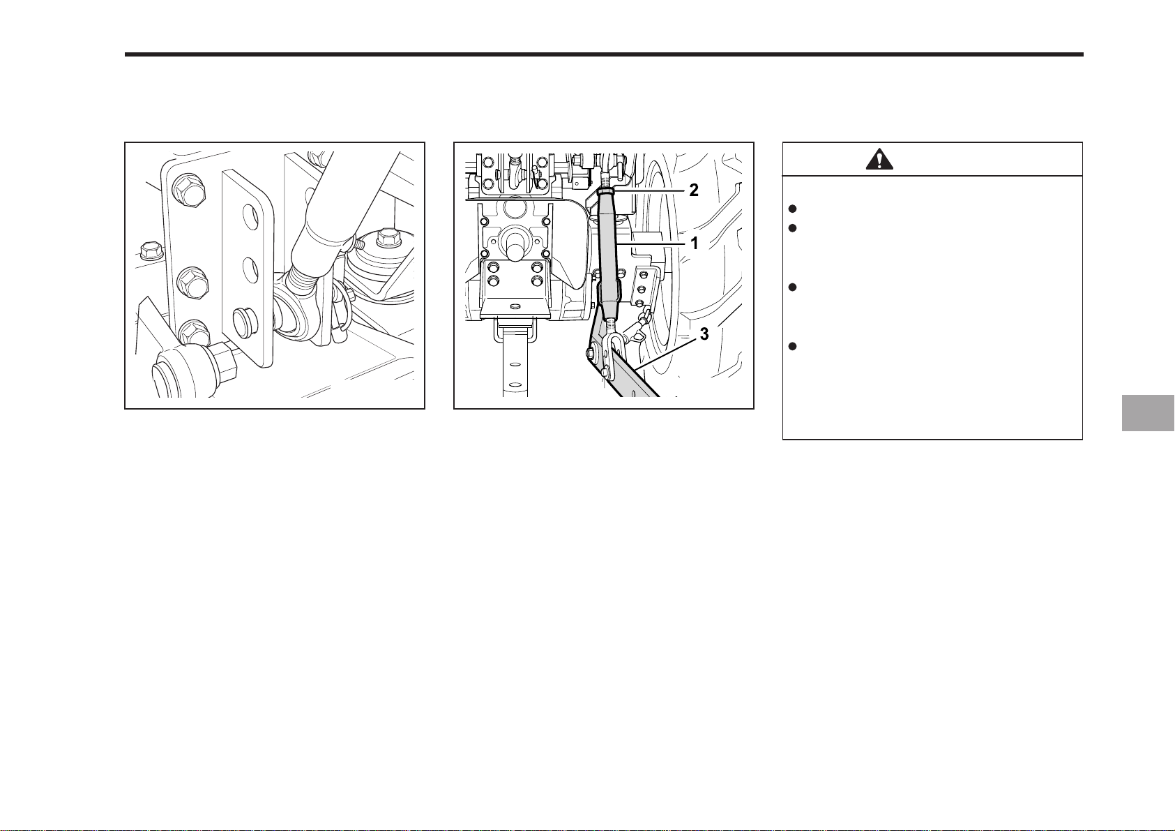
3-POINT HITCH
THREE-POINT HITCH & DRAWBAR 8-3
MAKE PREPARATIONS FOR
A TT ACHING IMPLEMENT
SELECTING THE TOP LINK MOUNTING
HOLES
Select the proper set of holes by referring to the “Hydraulic Control Unit Use
Reference Chart” in Hydraulic Unit
section.
ATT ACHING AND DETACHING
IMPLEMENTS
196O803A196O802A
(1) Lifting Rod (Right) (3) Lower Linle
(2) Nut
CAUTION
To avoid personal injury:
Be sure to stop the engine.
Do not stand between tractor and
implement unless parking brake
is applied.
Before attaching or detaching
implement, locate the tractor and
implement on a firm level surface.
Whenever an implement or other
attachment is connected to the
tractor 3-point hitch, check full
range of operation for interference,
binding or P.T.O separation.
LIFTING ROD (RIGHT)
Lift Rod - To adjust the horizontal posi-
tion of the implement twist the turn buckle
on the right lift rod. Most implements are
designed to operate level. Set the position desired by tightening the set nut
against the turn buckle.
DRAWBAR
Remove the drawbar if close mounted
implement is being attached.
TOP LINK
1. Adjust the angle of the implement to
the desired position by shortening or
lengthening the top link.
2. The proper length of the top link varies
according to the type of implement
being used.
Page 74

8-4 CK20
DRA WBAR
ADJUSTING DRAWBAR LENGTH
W ARNING
Use caution when adjusting the
check chains. Heavy implement
can move causing harm.
To adjust the check chains, loosen the
set nuts and twist the turn buckles on
both sides until the desired amount of
sway is reached. (Refer to the table
below). Set the adjustment by tightening
the set nuts against the turn buckles.
196O805A196O804A
(1) T urn Buckle (3) Check Chains
(2) Nut
CHECK CHAINS
Check chains are used to adjust the side
sway that your implement has while in
use. Check Chains are also used to center the implement on the rear of the
tractor.
(1) P.T.O Shaft (3) Drawbar Pin
(2) Drawbar (A) Holes
WARNING
To avoid personal injury:
Never pull from the top link, the
rear axle or any point above the
drawbar. Doing so could cause
the tractor to tip over rearward
causing personal injury or death.
The drawbar load is referred to “IMPLEMENT LIMIT A TIONS” section.
Page 75

3-POINT HITCH CONTROL SYSTEM
9HYDRAULIC UNIT
AUXILIARY HYDRAULICS
Page 76
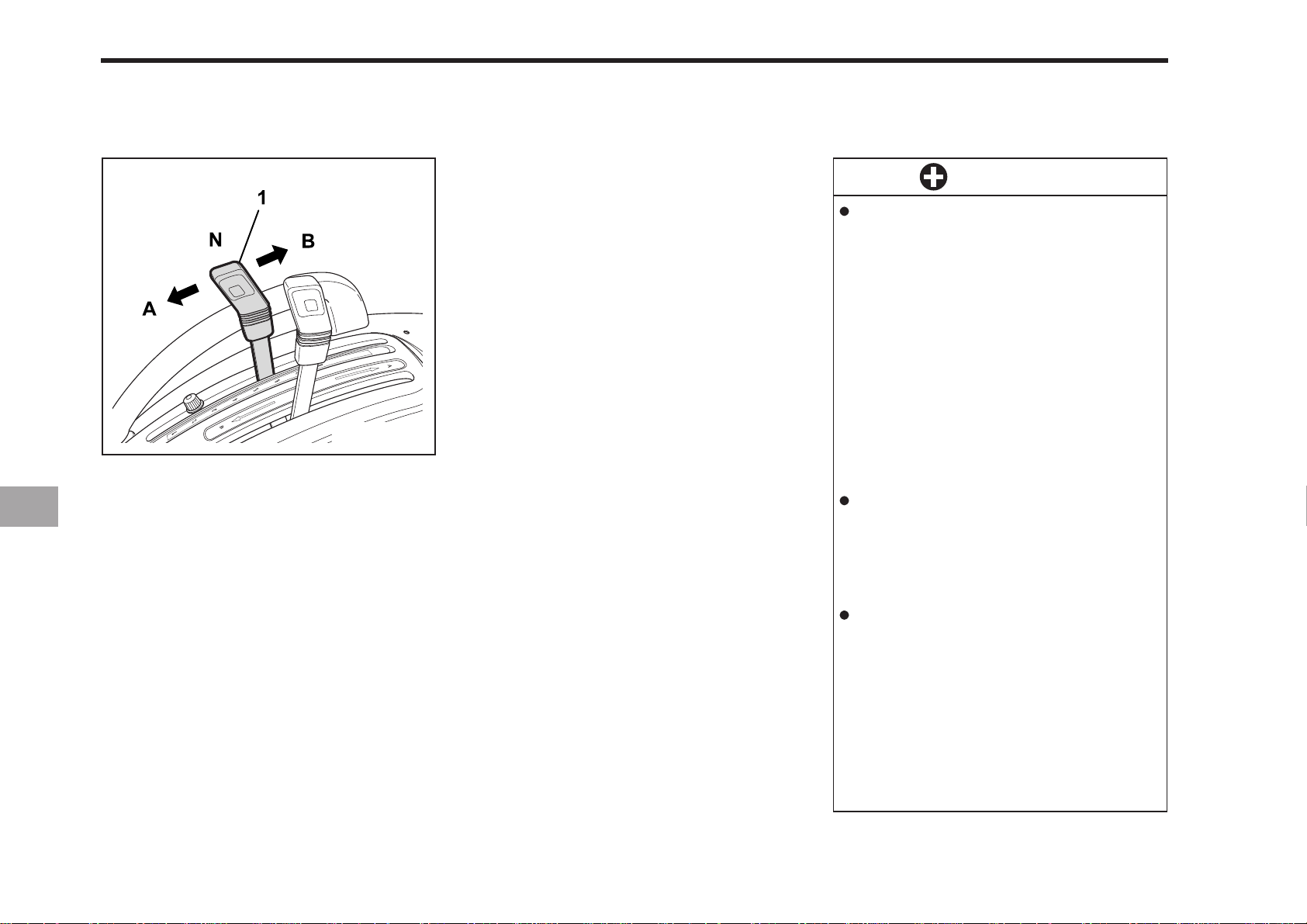
9-2 CK20
3-POINT HITCH CONTROL SYSTEM
HYDRAULIC CONTROL
(1) Hydraulic Control Lever
(A) DOWN (N) NEUTRAL
(B) UP
196O901A
Operating the hydraulic control lever actuates the hydraulic lift arm. This controls the elevation of the 3-point hitch
mounted implement.
IMPORTANT
If the 3-point hitch can not be
raised by setting the hydraulic
control lever to the “UP” position
after long term storage or when
changing the transmission oil, follow these air bleeding procedures.
1. Stop the engine.
2. Set the hydraulic control lever
to the “DOWN” position and
start the engine.
3. Operate the engine at low idle
speed for at least 30 seconds
to bleed air from the system.
Do not operate until the engine is
warmed up. If operation is attempted when the engine is still
cold, the hydraulic system may
be damaged.
If noises are heard when implement is lifting after the hydraulic
control lever has been activated,
the hydraulic mechanism is not
adjusted properly.
Unless corrected the unit will be
damaged.
Contact your KIOTI dealer for
adjustment.
Page 77
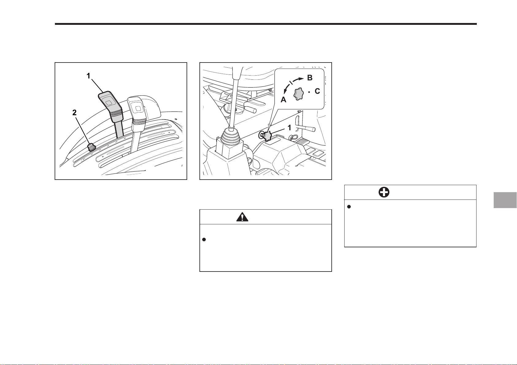
HYDRAULIC UNIT 9-3
IMPLEMENT LOWERING LIMIT
196O902A
(1) Hydraulic Control Lever
(2) Lock Bolt
The implement lowering limit can be
changed and adjusted by shifting the
locker.
LOWER LIMIT
The lower limit can be adjusted by moving the position of the locker. Shifting the
locker backward raises the lower limit
and shifting the locker forward lowers
the lower limit.
3-POINT HITCH LOWERING SPEED
196O903A
(1) 3-Point Lowering Speed Knob
(A) FAST (C) LOCK
(B) SLOW
CAUTION
To avoid personal injury:
Fast lowering speed may cause
damage or injury. Lowering speed
of implement should be adjusted
to two or more seconds.
The lowering speed of the 3-point hitch
can be controlled by adjusting the 3-point
lowering speed knob.
HYDRAULIC BLOCK TYPE OUTLET
Hydraulic block type outlet is useful when
adding hydraulically operated equipment
such as:
front end loader, front blade, etc.
WHEN IMPLEMENT IS ATTACHED
1. Remove the plugs.
2. Route the implement inlet, outlet, and
return hoses as shown in the
illustration.
3. Move the control screw groove to
“vertical position” when implement is
attached.
IMPORTANT
To prevent overheating and damage to the hydraulic system once
an implement is detached, be
sure the control screw is turned
back to the “Horizontal position”.
Page 78
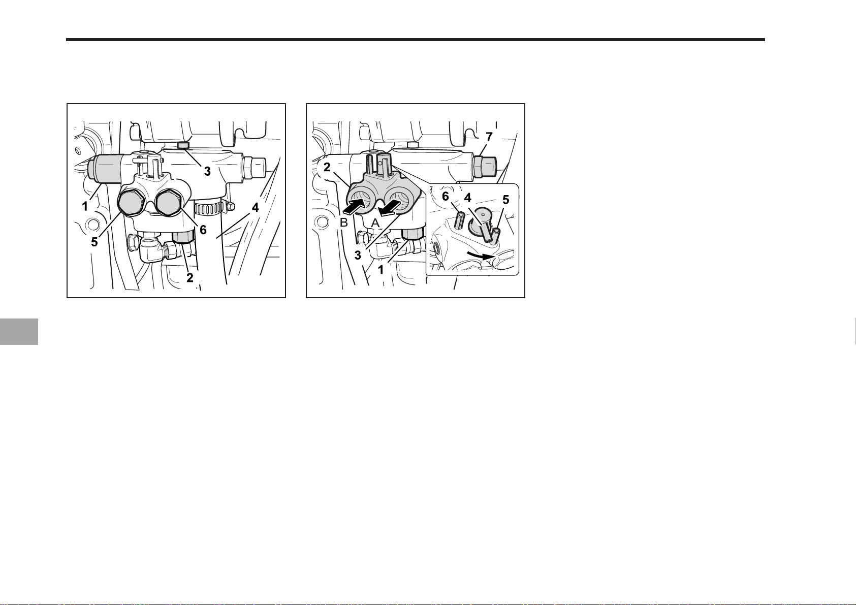
9-4 CK20
When implement is not attached When implement is attached
196O904A
(1) To Hydraulic Control Valve (3-point hitch)
(2) To Power steering (PS type only)
(3) From Gear Pump
(4) To Gear Pump (Relief Valve)
(5) From Implement
(6) T o Implement
196O905A
(1) Flow Priority Valve
(2) Inlet from Implements (PS 3/8 ´´)
(3) Outlet to Implements (PS 3/8´ ´)
(4) Directional Valve
(5) Pin (Setting Position for Attaching
Implements)
(6) Pin (Setting Position for Attaching no
Implement)
(7) Relief Valve
(A) Out (B) In
The main components of the hydraulic
block outlet are shown in the figure. The
hydraulic block outlet is used to take
power out from the tractor to operate the
implements that require hydraulic
pressure.
Page 79
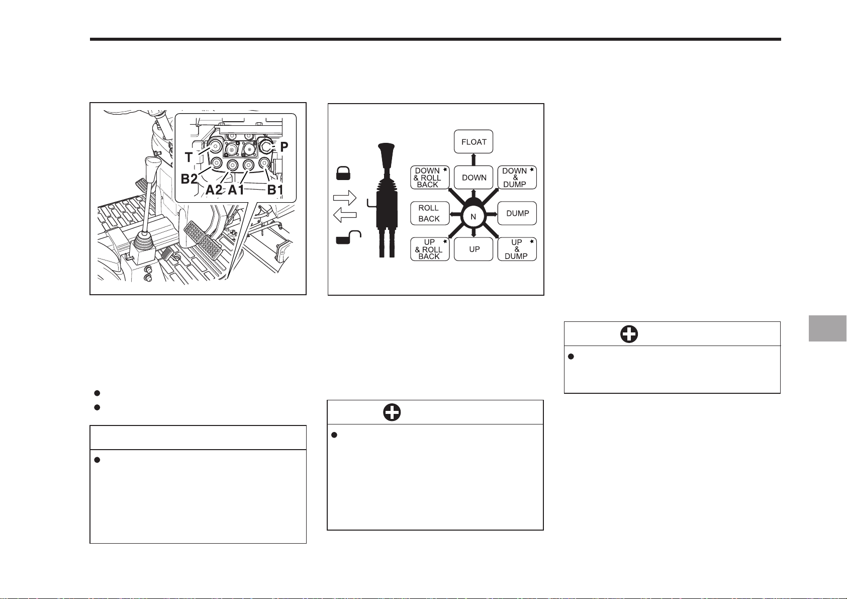
AUXILIARY HYDRAULICS
JOYSTICK VAL VE
(T) To the Tank
(P) From the Pump
(A1) A1 Port
(A2) A2 Port
(B1) B1 Port
(B2) B2 Port
Boom Cylinder : A1,B1
Bucket Cylinder : A2,B2
196O907A196O906A
To begin test operation, slightly move the
control lever from the “N” position. Slowly
raise the loader boom just enough for the
bucket to clear the ground when fully
dumped. Slowly work through the dump
and roll back cycles.
IMPORTANT
HYDRAULIC UNIT 9-5
REMOVE V ALVE TYPE
This loader control valve has two stage
dump position. The first dump position by
moving the lever to the right is the “Regular” dump position.
It has good power and control for dumping precisely. This position should be
used when operating another implement
with the loader’s control valve.
The second dump position (to further
right) features greater speed for
dumping. These two position are separated by a “Feel” position for your
convenience.
IMPORTANT
Do not move the control lever
into float position when the
bucket is off the ground.
NOTE
When the lever is at each corner position marked by*, boom and bucket
cylinders work at the same time.
However, the position marked by
cross is not recommended for scooping because of insufficient lift force.
If the boom or bucket does not
work in the directions indicated
in the label, lower the bucket to
the ground, stop the engine, and
relieve all hydraulic pressure. Recheck and correct all hydraulic
connections.
Page 80
9-6 CK20
REMOTE CONTROL VAL VE COUPLER
CONNECTING AND DISCONNECTING
CAUTION
To avoid personal injury:
Stop the engine and relieve pressure before connecting or disconnecting lines.
Do not use your hand to check
for leaks.
CONNECTING
1. Clean both couplers.
2. Remove dust plugs.
3. Insert the implement coupler to the trac-
tor hydraulic coupler.
4. Pull the implement coupler slightly to
make sure couplers are firmly
connected.
DISCONNECTING
1. Lower the implement first to the
ground to release hydraulic pressure
in the hoses.
2. Clean the couplers.
3. Relieve pressure by moving hydraulic
control levers with engine shut off.
Pull the hose straight from the hydraulic coupler to release it.
4. Clean oil and dust from the coupler,
then replace the dust plugs.
NOTE
Your local KIOTI Dealer can supply
parts to adapt couplers to hydraulic
hoses.
Page 81
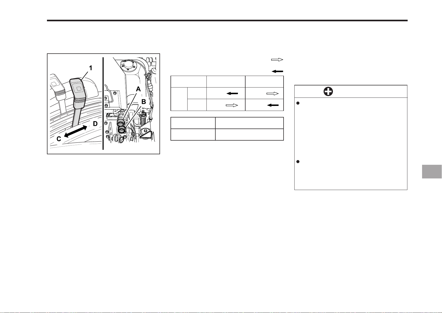
REMOTE CONTROL VAL VE LEVER
HYDRAULIC UNIT 9-7
(1) Remote Control Valve Lever
(A) A Port (C) Push
(B) B Port (D) Pull
196O908A
Lever (1)
A
Port
B
Port A, B
In
Out
Pressure
Returning
Push
Coupler Size
PT 1/2´´
Out
In
Move the lever up or down and hold. This
will raise or lower the implement. Lever
will return to neutral when released.
Pull
IMPORTANT
Do not hold the lever in the “pull”
or “push” position once the remote cylinder has reached the
end of the stroke, as this will
cause oil to flow through the relief valve. Forcing oil through the
relief valve for extended periods
will overheat the oil.
When using the tractor hydraulic
system to power front loader, do
not operate boom and bucket cylinders simultaneously.
Page 82
9-8 CK20
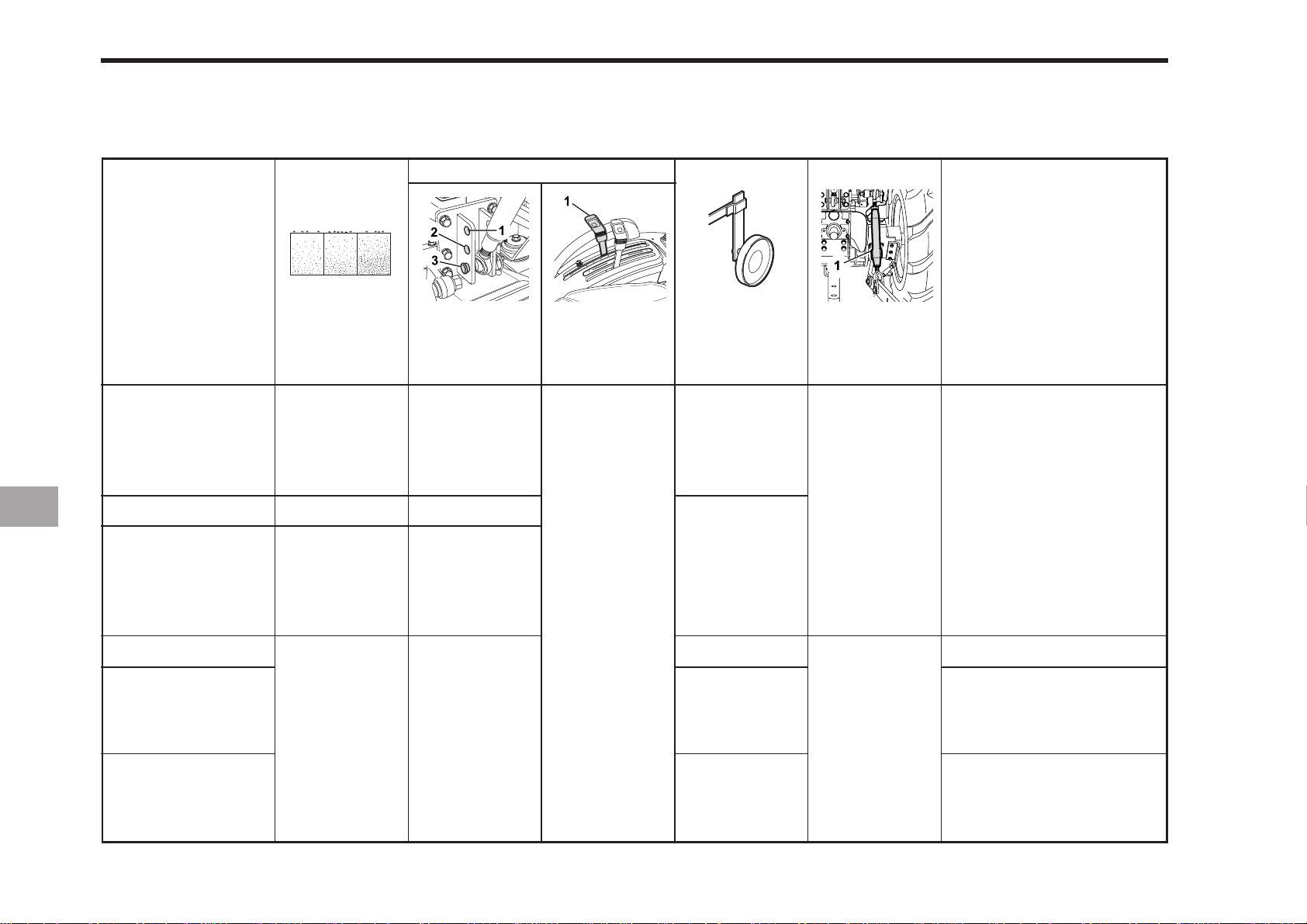
HYDRAULIC CONTROL UNIT USE REFERENCE CHART
In order to handle the hydraulics properly, the operator must be familiar with the following. Though this information may not be
applicable to all types of implements and soil conditions, it is useful for general conditions.
with draft control
Implement
Moldboard plow
Disc plow
Harrow
(spike, spring
tooth, disc type)
Webber, rider…
Earthmover, Digger,
scraper, manure
fork, rear carrier….
Soil
condition
Light soil
Medium soil
Heavy soil
-
-
-
Top link
mounting holes
1 or 2
2 or 3
3
2 or 3
2 or 3
-
Position
control lever Gauge wheel
-
YES/NO
Position
control
-
YES/NO
196O913A196O912A196O911A196O910A196O909A
Turn buckle
Loose
Tighten
Remarks
Adjust the Turn buckle so
that the implement can
move 5 to 6 cm (2.0 to 2.4 in.)
laterally.
Turn buckle should be
tight enough to prevent
excessive implement
movement when implement is in raised position.
-
With implements with
gauge wheels, lower the
position control lever all
the way.
Mower (mid-and
rear-mount type
Hayrake,tedder….
--
Page 83

TIRES, WHEELS
TIRES
TREAD
10
AND BALLAST
BALLAST
TRAVELING SPEED
Page 84
10-2 CK20
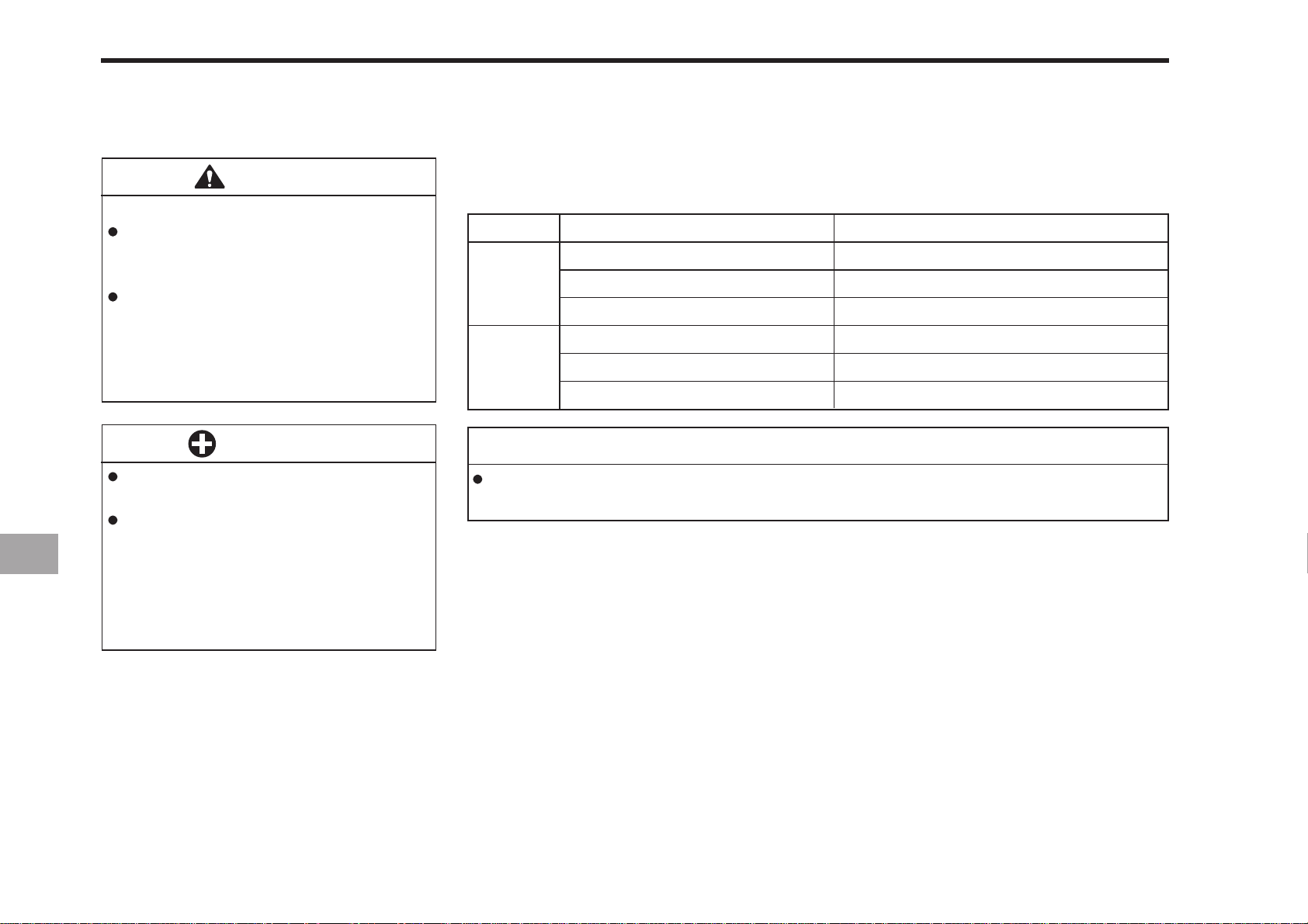
TIRES
INFLA TION PRESSURE
W ARNING
To avoid personal injury:
Do not attempt to mount a tire.
This should be done by a qualified
person with the proper equipment.
Always maintain the correct tire
pressure.
Do not inflate tires above the recommended pressure shown in the
operator’s manual.
IMPORTANT
Do not use tires larger than
specified.
When you intend to mound different size of tires from equipped
ones, consult your dealer about
front drive gear ratio for details.
Excessive wear of tires may occur due to improper gear ratio.
Though the tire pressure is factory-set to the prescribed level, it naturally drops
slowly in the course of time. Thus, check it everyday and inflate as necessary.
Inflation Pressure
20 7 kPa (2.1 kgf/cm
20 7 kPa (2.1 kgf/cm
27 6 kPa (2.8 kgf/cm
19 3 kPa (2.0 kgf/cm
15 2 kPa (1.5 kgf/cm
24 1 kPa (2.5 kgf/cm
2
, 30 psi)
2
, 30 psi)
2
, 40 psi)
2
, 28 psi)
2
, 22 psi)
2
, 35 psi)
Rear
Front
Tire sizes
9.5 - 16, 6PR
33 x 12.5 - 16.5, 4PR
12 - 16.5, 6PR
6 - 12, 4PR
23 x 8.50 - 12, 4PR
23 x 8.50 - 12, 6PR
NOTE
Maintain the maximum pressure in front tires, if using a front loader or when equipped
with a full load of front weights.
Page 85
TREAD
TIRES, WHEELS AND BALLAST 10-3
FRONT WHEELS
Front tread can not be adjusted.
IMPORTANT
Do not turn front discs to obtain
wider tread.
NOTE
IND… for Industrial
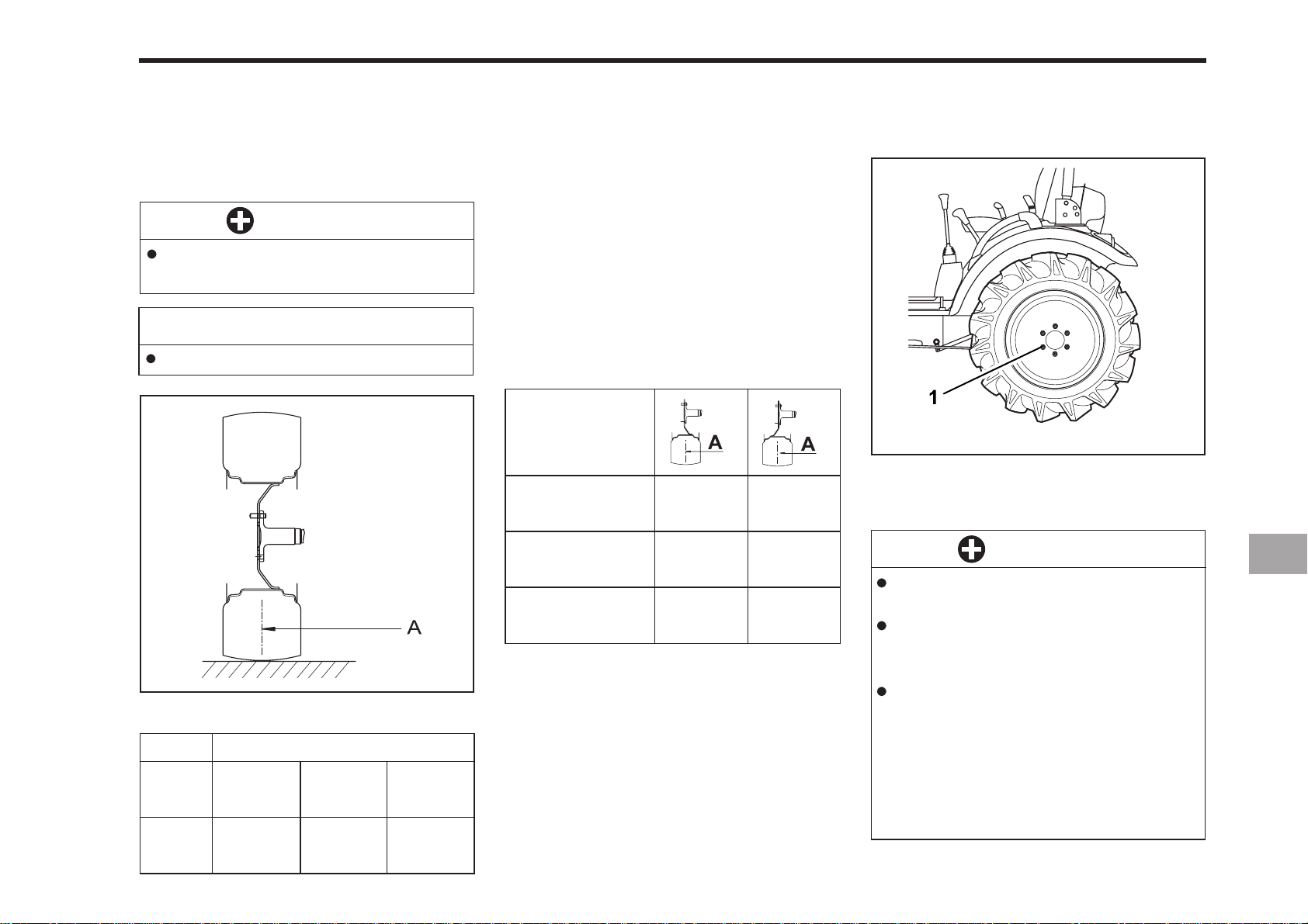
196OA01A
(A) Tread
Models
Tires
Tread
6 - 12
Farm
909 mm
(35.8 in.)
CK 20, CK20H
23x8.50-12
Turf
1,014 mm
(39.9 in.)
23x8.50-12
1,014 mm
(39.9 in.)
IND
REAR WHEELS
Rear wheel tread width can be adjusted
as shown with the standard equipment
tires.
To change the tread width.
1. Remove the wheel rim and the disk
mounting bolts.
2. Change the position of the rim and disk
to the desired position, and then tighten
the bolts.
Models
CK20, CK20H
9.5 - 16 Farm
CK20, CK20H
33x12.5-16.5Turf
CK20, CK20H
12 - 16.5 IND
A: Tread
890 mm
(35 in.)
-
-
935 mm
(36.8 in.)
995 mm
(39.2 in.)
1,015 mm
(40 in.)
196OA04A
(1) 215 N·m (22 kgf·m, 160 lbs·ft)
IMPORTANT
Always attach tires as shown in
the drawings.
If not attached as illustrated,
transmission parts may be
damaged.
When re-fitting or adjusting a
wheel, tighten the bolts to the
following torques then recheck
after driving the tractor 200 m (200
yards) and thereafter according
to service interval.
(See “MAINTENANCE” section)
Page 86
10-4 CK20
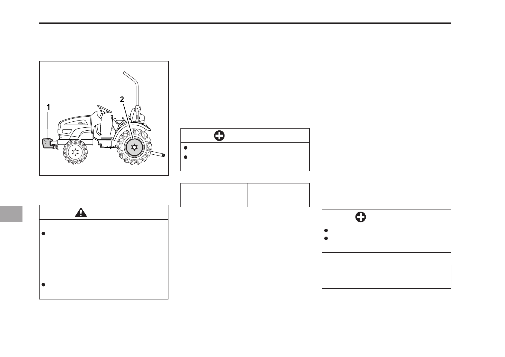
BALLAST (OPTIONAL)
FRONT BALLAST
196OA05A
(1) Front End Weights
(2) Rear Wheel Weights
CAUTION
To avoid personal injury:
Additional ballast will be needed
for transporting heavy implements.
When the implement is raised,
drive slowly over rough ground,
regardless of how much ballast
is used.
Do not fill the front wheel with liquid to maintain steering control.
FRONT END WEIGHTS
Front end weights can be attached to
the front of the tractors bumper. You
should consult your implement owner’s
manual for the required amount of weight
or contact your local KIOTI dealer for a
recommendation.
IMPORTANT
Never overload the tires.
Do not add more weight than is
necessary, or is indicated in chart.
17 kg X 3 Pieces
Maximum weight
(112 lbs.)
REAR BALLAST
Weight should be added to the rear
wheels only if it is needed to improve
traction or stability. The amount of weight
should directly correspond to the job at
hand and should be removed when not
needed.
The weight should be added to the tractor in the form of liquid ballast, rear wheel
weights or both.
REAR WHEEL WEIGHTS
The rear wheel weights can be attached
to the rear wheel. See your implement
owner’s manual for the proper amount
of weight or consult you local KIOTI
dealer.
IMPORTANT
Do not overload tires.
Add no more weight than indicated in chart.
Maximum weight
per wheel
20 kg X 2 Pieces
(88.2 lbs.)
Page 87
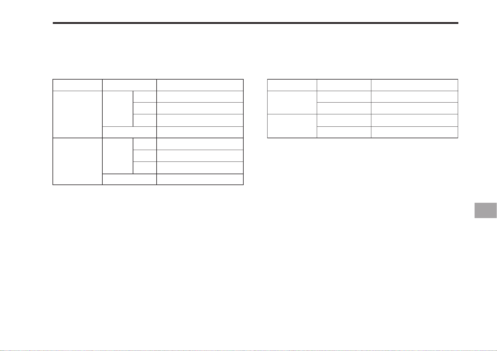
TRA VELING SPEED
* A T RATED ENGINE RPM WITH STANDARD TIRES.
TIRES, WHEELS AND BALLAST 10-5
CK20
HI - LOW
LOW
HIGH
Main
Forward
Reverse
Forward
Reverse
km/h(mile/h) km/h(mile/h)
Speed
1
2
3
1
2
3
1.10 ( 0.680 )
1.70 ( 1.056 )
3.50 ( 2.170 )
1.36 ( 0.845 )
5.11 ( 3.175 )
7.88 ( 4.896 )
16.24 ( 10.091 )
6.31 ( 3.920 )
CK20H
HI - LOW
LOW
HIGH
Main
Forward
Reverse
Forward
Reverse
Speed
0 ~ 5.80 ( 0 ~ 3.604 )
0 ~ 3.62 ( 0 ~ 2.249 )
0 ~ 14.17 ( 0 ~ 8.805 )
0 ~ 9.37 ( 0 ~ 5.822 )
Page 88

Page 89

SERVICE INTERVALS
11MAINTENANCE
LUBRICANTS
Page 90
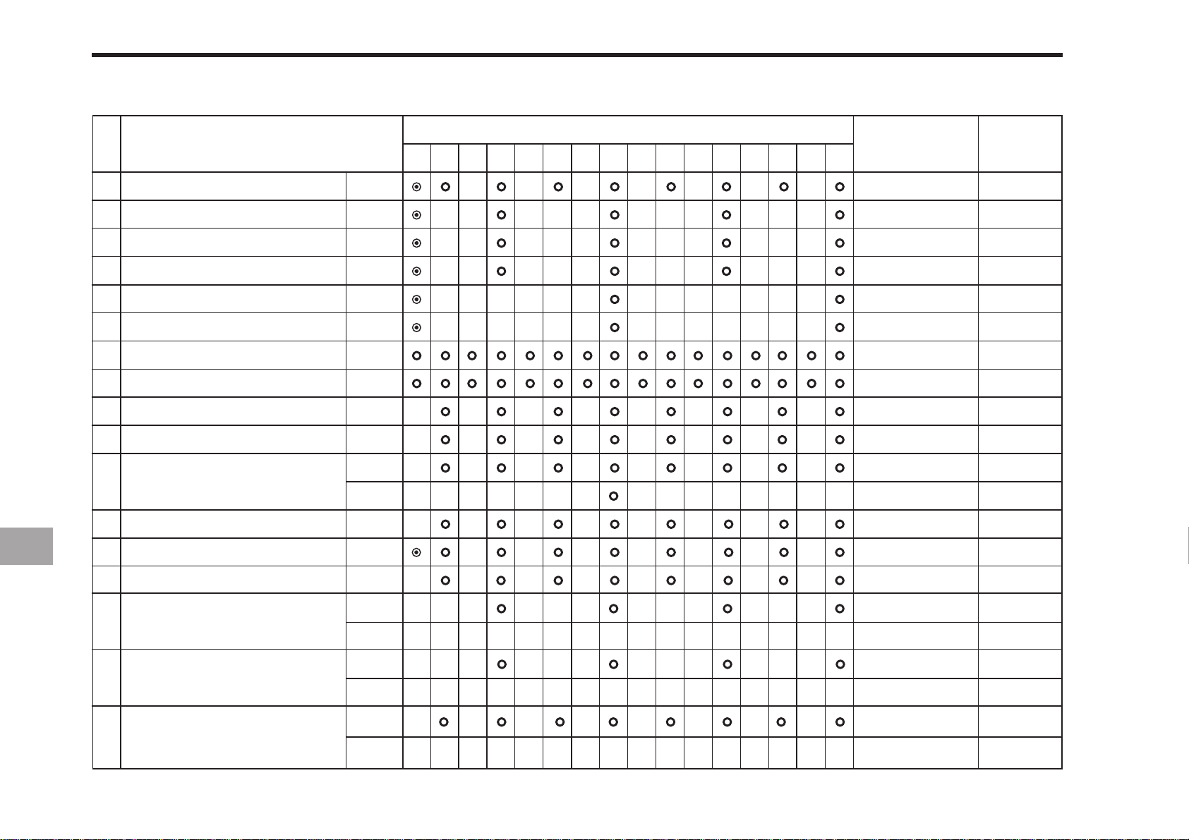
11-2 CK20
SERVICE INTER V ALS
No. Period
Engine oil
1
Engine oil filter
2
Hydraulic oil filter
3
Transmission oil filter (HST)
4
Transmission fluid
5
Front axle case oil
6
Greasing
7
Wheel bolt torque
8
Battery condition
9
Air cleaner element
10
Fuel filter element
11
Fan belt
12
Change
Replace
Replace
Replace
Change
Change
Check
Check
Clean
Clean
Replace
Adjust
Indication on hour meter
50
100 150 200 250 300 350400 450 500 550 600 650 700 750 800
Since then
Every 100 Hr
Every 200 Hr
Every 200 Hr
Every 200 Hr
Every 400 Hr
Every 400 Hr
Every 50 Hr
Every 50 Hr
Every 100 Hr
Every 100 Hr
Every 100 Hr
Every 400 Hr
Every 100 Hr
Reference
page
12-10
12-18
12-18,19
12-18,19
12-22
12-23
12-8
12-9
12-15
12-10,11
12-12
12-23
12-17
Clutch
13
Brake(Hand brake inclusion)
14
Radiator hose and clamp
15
Power steering oil line
16
Fuel line
17
Adjust
Adjust
Check
Replace
Check
Replace
Check
Replace
Every 100 Hr
Every 100 Hr
Every 200 Hr
Every 2 years
Every 200 Hr
Every 200 Hr
Every 100 Hr
Every 2 years
12-13
12-13
12-20
12-26
12-20
12-26
12-12
12-26
Page 91
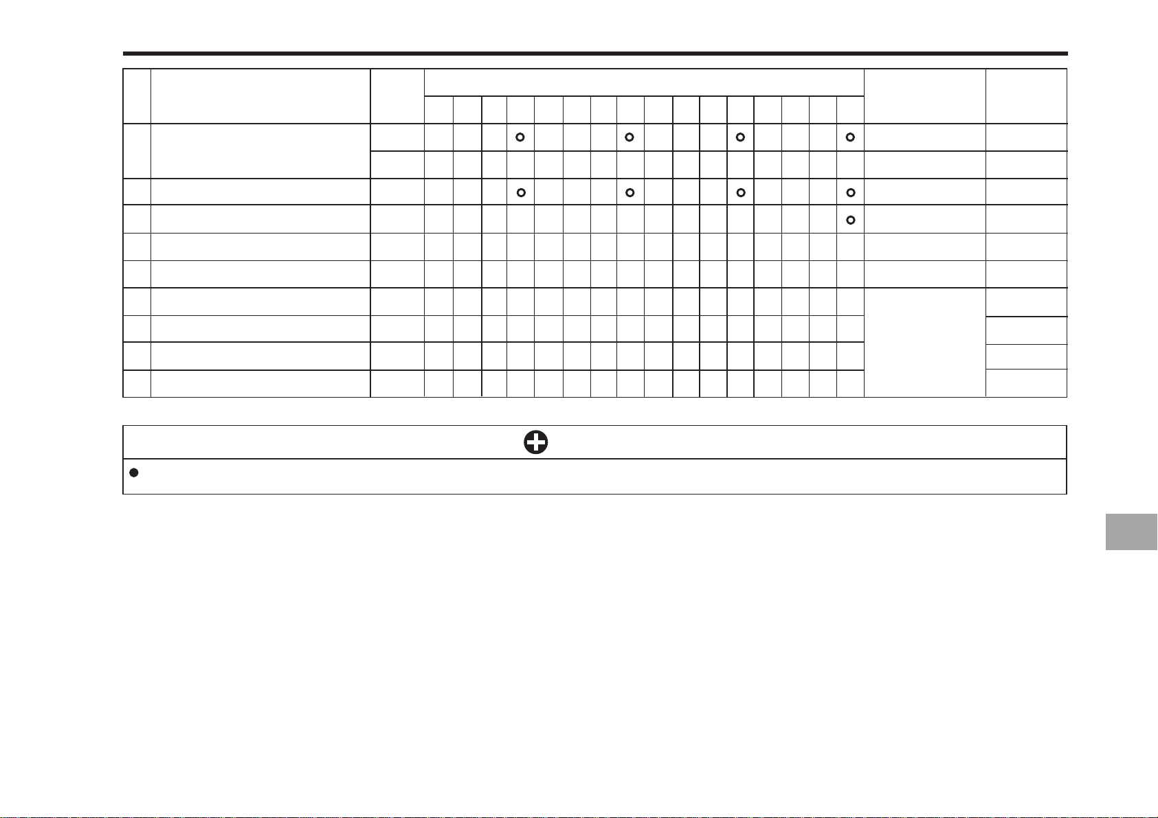
MAINTENANCE 11-3
No. Period
18
HST oil line (HST)
19
Toe-in
20
Engine valve clearance
21
Cooling system
22
Coolant
23
Fuel system
24
Clutch housing water
25
Fuse
26
Light bulb
The jobs indicated by
Indication on hour meter
100 150 200 250 300 350400 450 500 550 600 650 700 750 800
50
Check
Replace
Adjust
Adjust
Flush
Change
Bleed
Drain
Replace
Replace
IMPORTANT
must be done after the first 50 hours of operation.
Since then
Every 200 Hr
Every 200 Hr
Every 200 Hr
Every 800 Hr**
Every 2 years
Every 2 years
Service as
required
Reference
page
12-18,19
12-26
12-21
12-24
12-25
12-25
12-27
12-27
12-28
12-29
Page 92
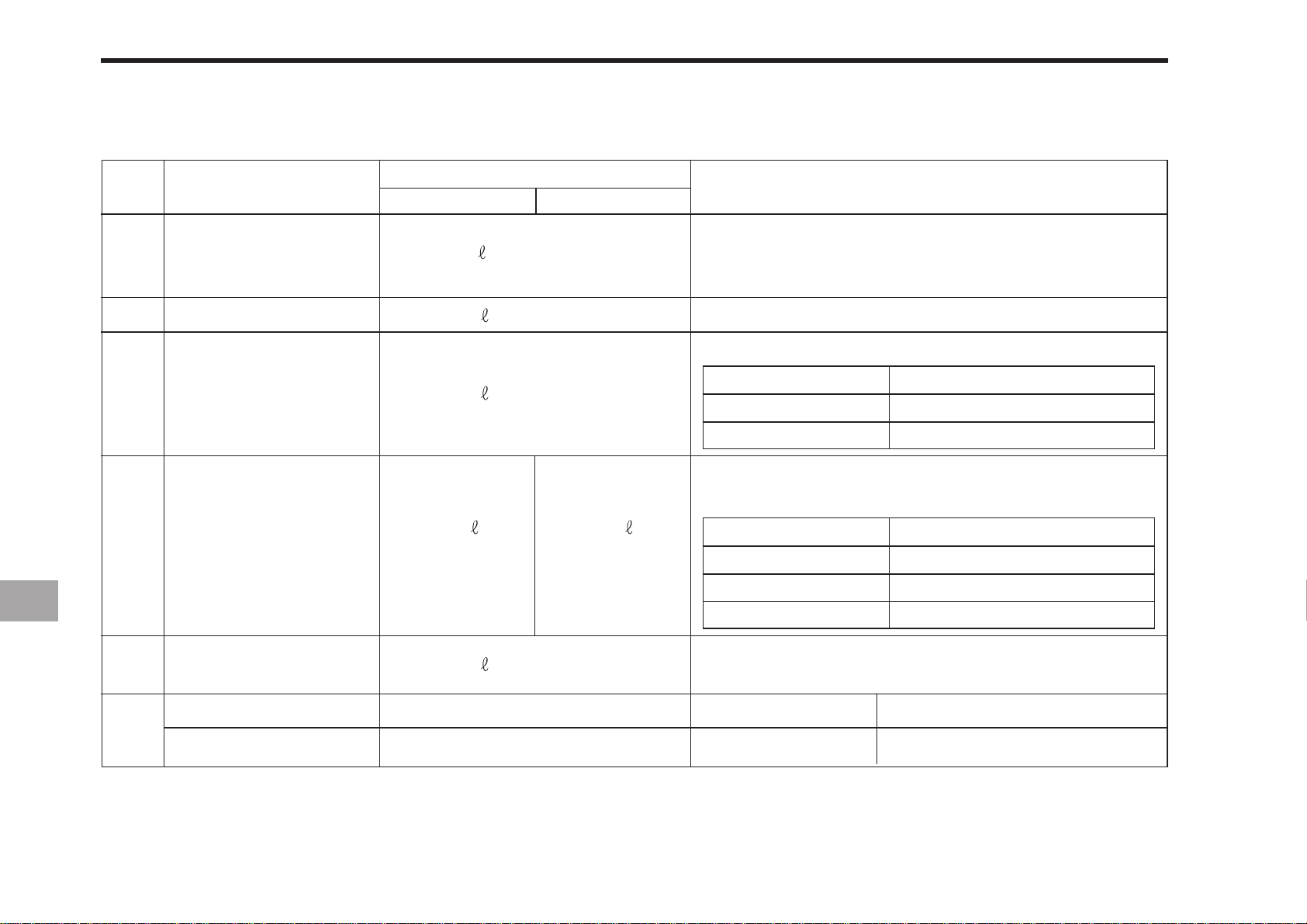
11-4 CK20
LUBRICANTS
No. Locations
1
2
3
4
Fuel
Coolant
Engine crankcase
Transmission case
Capacities
CK20HST CK20
20
(5.28 U.S.gal.)
5.7
(1.50 U.S.gal.)
2.6
(0.69 U.S.gal.)
18.5
(4.89 U.S.gal.)
(5.71 U.S.gal.)
21.6
Lubricants
No.2-D diesel fuel
No.1-D diesel fuel if temperature is below
-10°C (14°F)
Fresh clean water with anti-freeze
Engine oil: API Service Classification CC or CD
Above 25°C (77°F)
0 to 25°C (32 to 77°F)
Below 0°C (32°F)
SAE30, SAE10W-30 or 10W-40
SAE20, SAE10W-30 or 10W-40
SAE10W, SAE10W-30 or 10W-40
Multi-grade transmission fluid the fluid listed below or
equivalent are recommended.
Maker
Shell
Mobil
Exxon
Brand(Standard)
DONAX-TD,DONAX-TM
Mobile Fluid 350
Torque Fluid 56
5
(4WD only)
Greasing
No. of greasing points
(0.82 U.S.gal.)
3.1
SAE 90 gear oil
Capacity
Type of grease
6
Front axle case
Battery terminal
2
Moderate amount
Multipurpose type grease
Page 93

HOW TO OPEN THE HOOD
DAILY CHECK
EVERY 50 HOURS
EVERY 100 HOURS
EVERY 200 HOURS
EVERY 400 HOURS
12PERIODIC SERVICE
EVERY 600 HOURS
EVERY 800 HOURS
EVERY 1 YEAR
EVERY 2 YEAR
SERVICE AS REQUIRED
Page 94
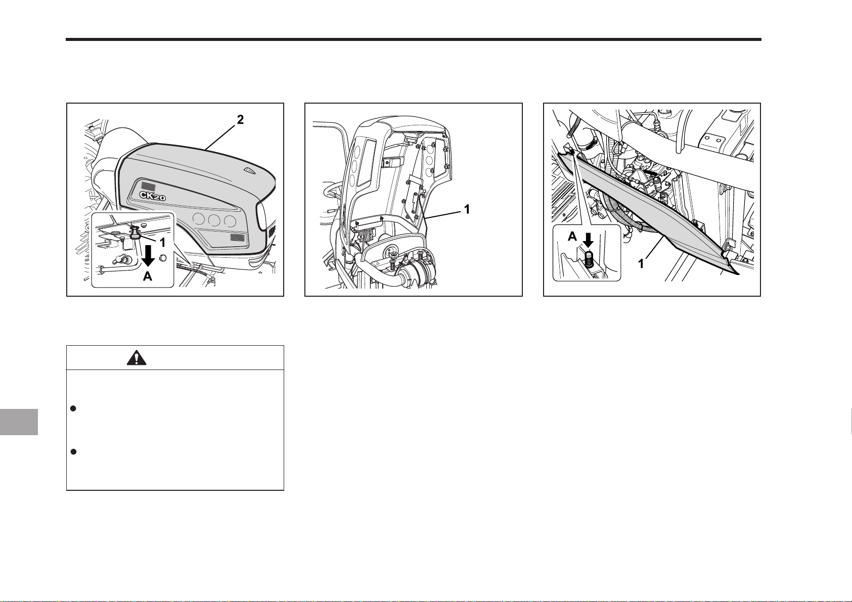
12-2 CK20
HOW TO OPEN THE HOOD
HOOD
(1) Knob (A ) PULL
(2) Hood
CAUTION
To avoid personal injury from contact with moving parts:
Never open the hood or engine
side cover while the engine is
running.
Do not touch muffler or exhaust
pipes while they are hot; severe
burns could result.
196OC02A
(1) Hood Rod
To open the tractors hood you should
first pull the knob to release the latch.
ENGINE COVER
196OC03A196OC01A
(1) Sider Cover (A) Push
To remove the sider cover.
It is not necessary to remove the side
cover to do daily check on your tractor.
Page 95
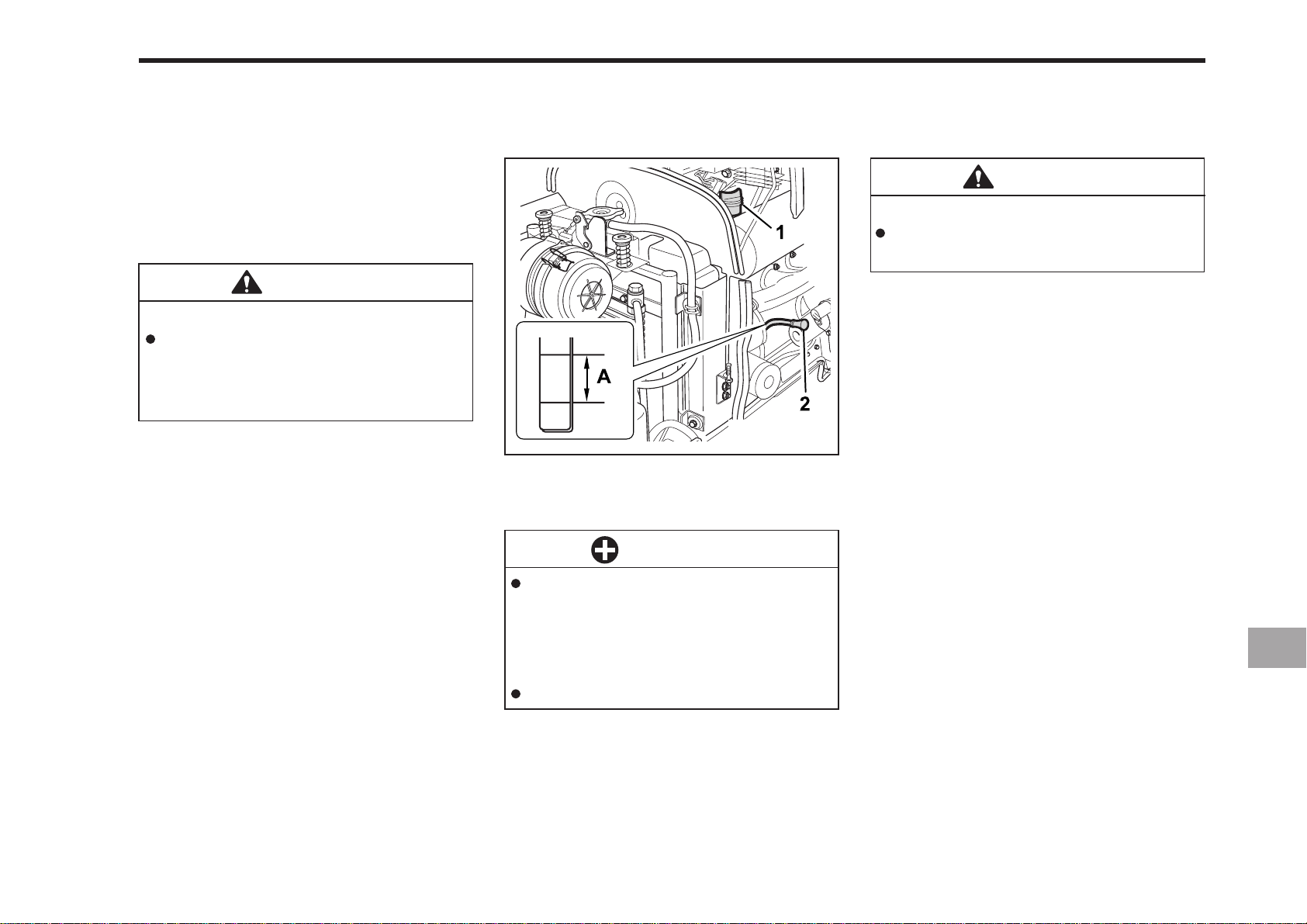
DAIL Y CHECK
PERIODIC SERVICE 12-3
CHECKING ENGINE OIL LEVEL
For your own safety and maximum service life of the machine, make a thorough
daily inspection before operating the
machine to start the engine.
CAUTION
To avoid personal injury:
Be sure to check and service the
tractor on a flat place with the engine shut off and the parking
brake “ON”.
WALK AROUND INSPECTION
Look around and under the tractor for
such items as loose bolts, trash buildup, oil or coolant leaks, broken or worn
parts.
196OC05A
(1) Oil Inlet (2) Dipstick
(A) Oil Level is Acceptable Within This Range.
IMPORTANT
When using an oil of different
maker or viscosity from the previous one, remove all of the old
oil. Never mix two different types
of oil.
If oil level is low, do not run engine.
CAUTION
To avoid personal injury:
zz
Be sure to stop the engine be-
z
zz
fore checking the oil level.
1. Park the machine on a flat surface.
2. Check engine oil before starting the
engine or 5 minutes or more after the
engine has stopped.
3. To check the oil level, draw out the
dipstick, wipe it clean, replace it, and
draw it out again. Check to see that
the oil level lies between the two
notches. If the level is too low, add
new oil to the prescribed level at the
oil inlet.
(See “LUBRICANTS” in Maintenance
Section)
Page 96
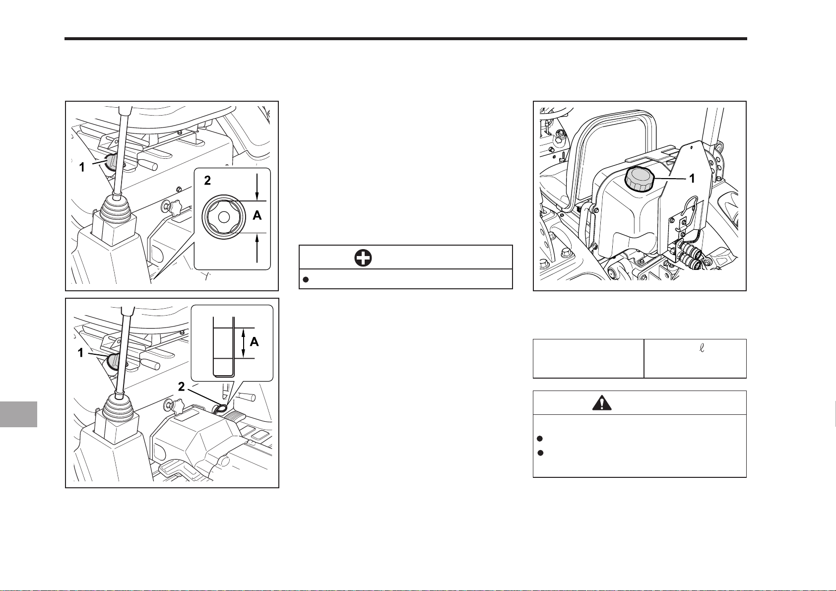
12-4 CK20
CHECKING TRANSMISSION FLUID
LEVEL
CK20
196OC06A
CK20H
1. Park the machine on a flat surface,
lower the implement and shut off
engine.
2. View the fluid level through the fluid
level gauge. If the level is too low, add
new oil to the prescribed level at the
oil inlet.
(See “LUBRICANTS” in Maintenance
Section)
IMPORTANT
If oil level is low, do not run engine.
CHECKING AND REFUELING
196OC04A
(1) Fuel T ank Cap
20
Fuel tank capacity
(5.28 U.S.gal.)
196OC07A
(1) Oil Filling Plug
(2) Gauge
(A) Oil Level is Acceptable Within This Range.
CAUTION
To avoid personal injury:
Do not smoke while refueling.
Be sure to stop the engine before refueling.
Page 97
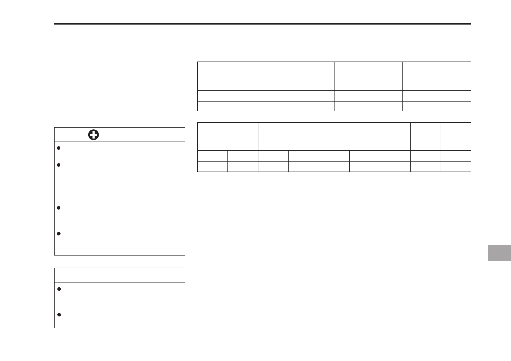
1. Turn the key switch to “ON”, check
the amount of fuel by fuel gauge.
2. Fill fuel tank when fuel gauge shows
1/4 or less fuel in tank.
3. Use grade No.2-Diesel fuel at temperatures above -10°C (14°F).
Flash Point,
°C (°F)
Min
52 (125)
Water and Sediment,
volume %
Max
0.05
PERIODIC SERVICE 12-5
Carbon Residue on, 10
percent Residuum, %
Max
0.35
Ash,
weight %
Max
0.01
IMPORTANT
Do not permit dirt or trash to get
into the fuel system.
Be careful not to let the fuel tank
become empty, otherwise air will
enter the fuel system, necessitating bleeding before next engine start.
Be careful not to spill during
refueling. If should spill, wipe it
off at once, or it may cause a fire.
To prevent condensation (water)
accumulation in the fuel tank, fill
the tank before parking overnight.
NOTE
No.2-D is a distillate fuel of lower volatility for engines in industrial and heavy
mobile service. (SAE J313 JUN87)
Grade of Diesel Fuel Oil According to
ASTM D975
Distillation
Temperatures, °C(°F)
90% Point
Min
282 (540)
Max
338 (640)
Viscosity Kinematic
cSt or mm
Min
1.9
2
/s at 40°C
Max
4.1
Viscosity Saybolt,
SUS at 100°F
Min
32.6
Max
40.1
sulfur,
weight %
Max
0.50
Copper
Strip
Corrosion
Max
No.3
Cetane
Number
Min
40
Page 98
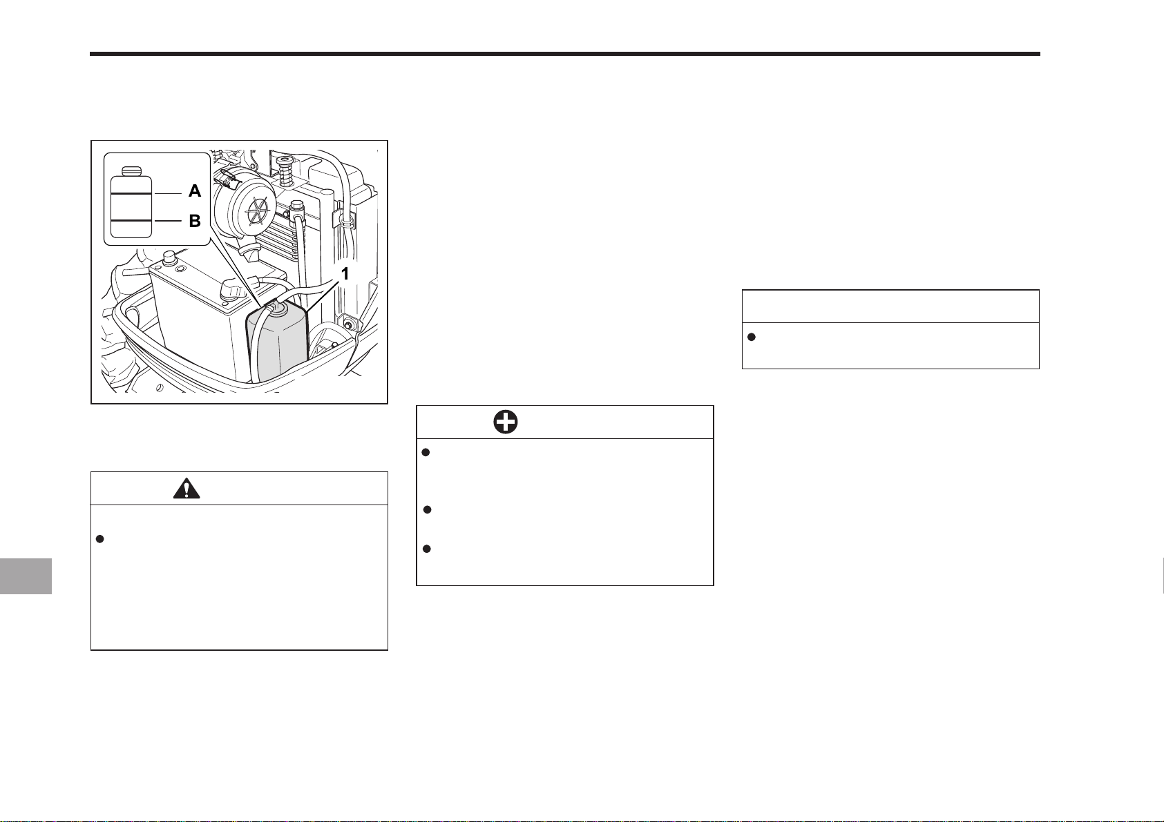
12-6 CK20
CHECKING COOLANT LEVEL
196OC08A
(1) Recovery T ank
(A) FULL (B) LOW
CAUTION
To avoid personal injury:
Do not remove radiator cap while
coolant is hot. When cool, slowly
rotate cap to the first stop and
allow sufficient time for excess
pressure to escape before removing the cap completely.
1. Check to see that the coolant level is
between the “FULL” and “LOW” marks
of recovery tank.
2. When the coolant level drops due to
evaporation, add water only up to the
full level.
In case of leakage, add anti-freeze and
water in the specified mixing ratio up
to the full level.
(See “Flush Cooling System and
Changing Coolant” in every 2 yours
maintenance.)
IMPORTANT
If the radiator cap has to be
removed, follow the caution above
and securely retighten the cap.
Use clean, fresh water and antifreeze to fill the recovery tank.
If water should leak, consult your
local KIOTI dealer.
CHECKING BRAKE AND CLUTCH
PEDALS
1. The brake and clutch pedals should
be inspected for free travel, and
smooth operation.
2. You should adjust these pedals if an
incorrect measurement is found. (See
“adjusting clutch and brake pedals” in
the 100 hour maintenance schedule.)
NOTE
Brake pedals should be equal when
depressed.
Page 99
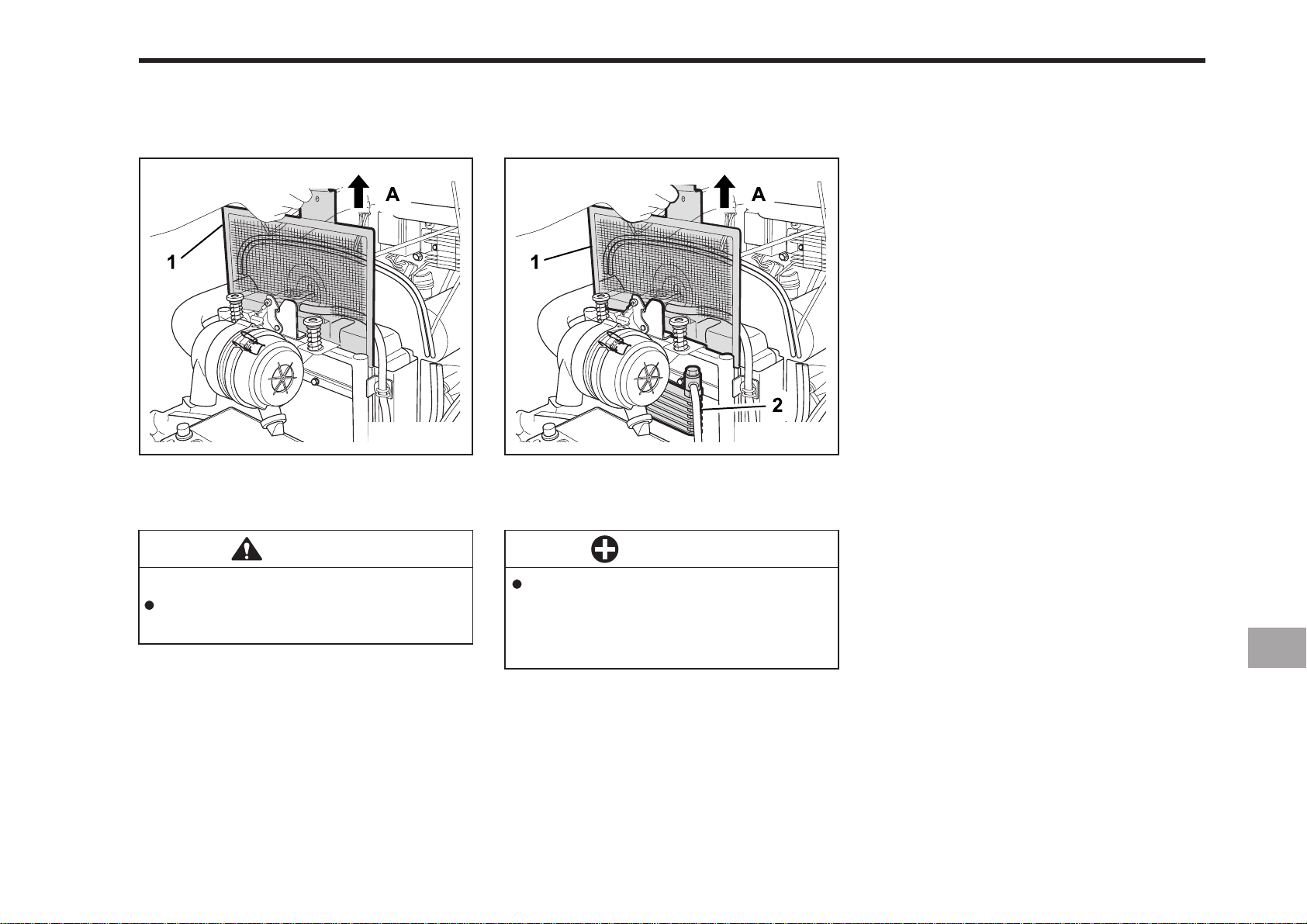
PERIODIC SERVICE 12-7
CLEANING GRILL, RADIA TOR SCREEN
AND OIL COOLER SCREEN
CK20
196OC09A
(1) Radiator Screen (A) D ETACH (2) Oil Cooler Screen
CAUTION
To avoid personal injury:
Be sure to stop the engine before removing the screen.
CK20H
IMPORTANT
Grill and screen must be clean
from debris to prevent engine
from overheating and to allow
good air intake for the air cleaner.
CHECKING GAUGES, METER AND
EASY CHECKER
1. Inspect the instrument panel for broken gauge(s), meter(s) and Easy
Checker lamps.
2. Replace if broken.
CHECKING HEAD LIGHT,
HAZARD LIGHT ETC.
1. Inspect the lights for broken bulbs and
lenses.
2. Replace if broken.
196OC10A
CHECKING SEAT BELT AND ROPS
1. Always check condition of seat belt
and ROPS attaching hardware before
operating tractor.
2. Replace if damaged.
1. Check front grill and side screens to
be sure they are clean of debris.
2. Detach the screen and remove all the
foreign material.
Page 100
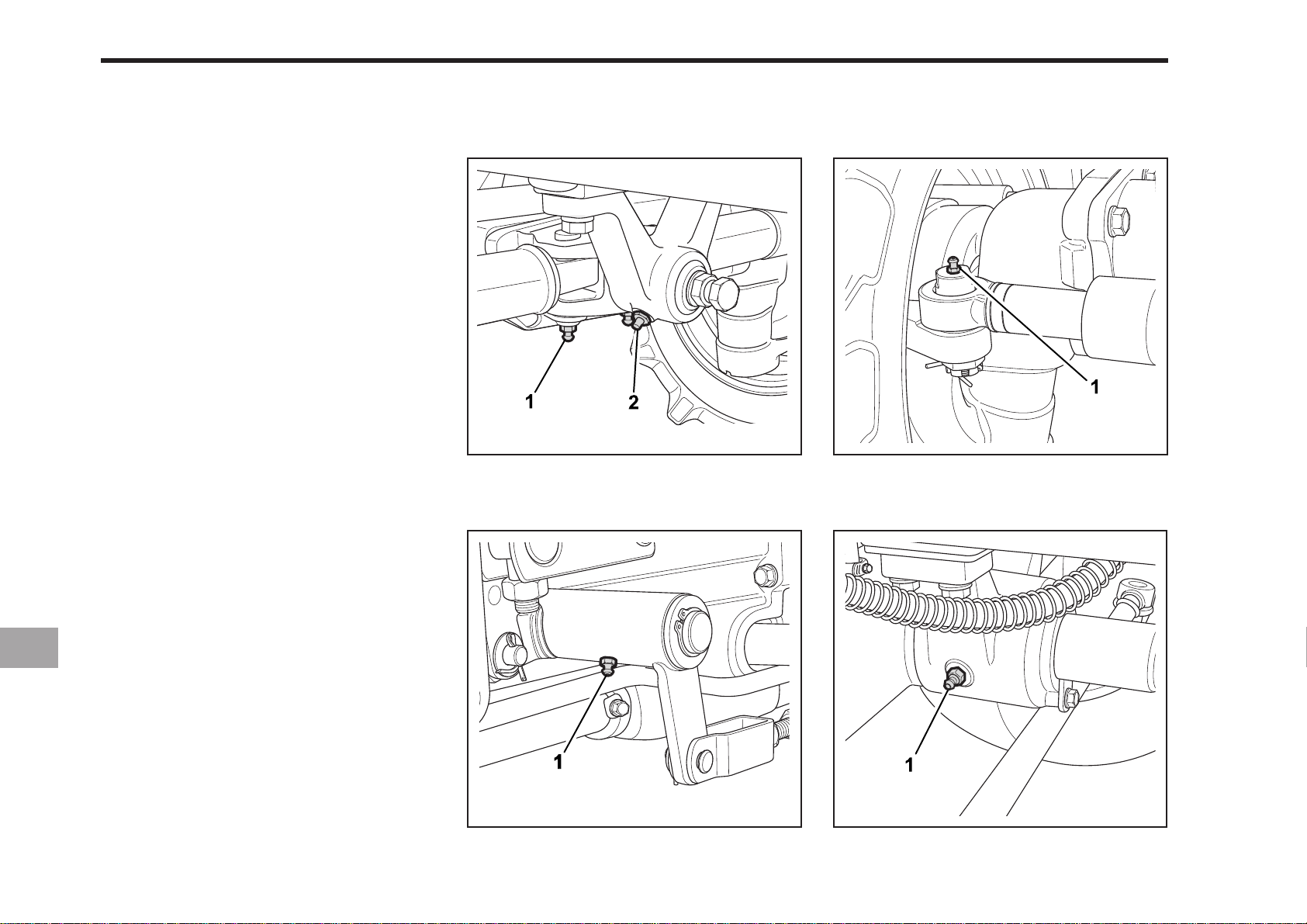
12-8 CK20
EVERY 50 HOURS
LUBRICA TING GREASE FITTINGS
Y ou should apply a small amount of multipurpose grease to the following pints
every 50 hours or as needed.
If your tractor is operated in extremely
wet, muddy, or dusty conditions you
should lubricate the fittings more often.
196OC11A
(1) Grease Fitting (Power steering cylinder)
(RH, LH)
(2) Grease Fitting (Front bracket)
196OC13A
(1) Grease Fitting (Brake Lever RH, LH)
196OC12A
(1) Grease Fitting (Power steering cylinder)
(RH, LH)
196 OC14A
(1) Grease fitting (Rear bracket)
 Loading...