

Kioti CK30 Wiring Diagram

CHAPTER 10
ELECTRIC SYSTEM


1. ELECTRIC SYSTEM
1.1 WIRING DIAGRAM
ELECTRIC SYSTEM
D
C
5.0R
B
5.0R
SLOW BLOW FUSE
BATTERY
E
003
002
5.0R
5.0R
60A
5.0R
5.0R
2.0RB
3.0RW
5.0R
RLY: STARTER
ALTERNATOR
IC REG
2.0B
001
3
3.0R
028
003
3.0RL
001
030
S
STARTER MOTOR
003
0.85LB
0.85B
5.0R
2.0RB
011
3.0RW
006
5.0R
003
3.0R
003
AM ACC M G
OFF
ACC
ON
GL
SW: MAIN
ST
0.85LB
028
SW: SAFETY(CLUTCH)
0.85B
M
0.5YL
0.85RW
3.0RW
5.0R
18
3.0RW
006
029
0.85RB
3.0RW
5 A
ST
3.0RW
006
5.0R
003
5 A
3.0RW
006
3.0R
003
5 A
3
0.85R
0.85LB
028
ST ON
LAMP
0.5GrY
18
5
025
GND
OUT
0.85RB
029
RLY: PREHEAT
0.85B
001
PREHEAT PLUG
5.0R
FFT/HOUR CONT.
GND
IN:CHARGE
0.5P
17
5.0BR
031
0.5B
0.85B
0.85RW
0.85LY
027
009
PREHEAT CONT.
0.85RW
0.85RW
009
103
DIODE(2P)
1
17
0.5PB
039
0.85B
2
SIGNAL IN
0.5WR
026 032
COOLANT TEMP. SENSOR
0.85B
001
OUT:HOUR.
0.5LW
041038
15
0.5WR
036
ON
OUT: TACHO.
IN:PICK UP
0.5W
037
PICK UP SENSOR
0.5B
REAR COMBI LAMP(LH)
21W
STOP5WPOSITION
023
0.85BY
16
0.85B
040
0.5LB
4
016
0.85BrW
7
006
003
21W
TURN SIGNAL
013
0.85RW
11
3.0RW
3.0R
TERMINAL
POSITION
OFF
1
2
REAR COMBI LAMP(RH)
21W 5W 21W
016
023
0.85B
0.85BY
0.85B
16
0.85BrW
7
015
014
12
3.0RW
5A
2.0RY
TURN SIGNALPOSITIONSTOP
0.85GW
COMBINATION SWITCH
TB1
1
018
017
016
0.85BrW
0.5Or
7
RLY: LOW BEAM
0.5B
001
FRT COMBI LAMP(LH)
21W
TURN SIGNAL5WPOSITION
013
0.85B
0.85RW
11
2
2.0G
1.25W
8
POSITION
004
0.85B
0.5Br
TERMINAL
1
OFF
2
0.5B
001
016
0.85BrW
7
10
B2
2.0G
020019
1.25Br
9
0.85B
3.0RW
006
3.0R
003
1.25L
012
RL
0.85RW
0.85GW
014
013
12
11
RLY: HIGH BEAM
FRT COMBI LAMP(RH)
21W
TURN SIGNAL POSITION
0.85B
0.85GW
12
016
7
013
0.85RW
11
5W
0.85BrW
1.25L
0.85B
HAZARD
WARNING
SWITCH
014
0.85GW
12
LOW
019014
1.25W
8
HEAD LIGHT
35W/35W
HIGH
020
001
2.0B
1.25Br
9
019
8
SW: HORN
POSITION
35W/35W
LOWHIGH
001
1.25W
HORN
2.0B
TERMINAL
FREE
PUSH
020
1.25Br
9
3.0R
20A
2.0G
004
0.85G
+
-
007
0.85Lg
10W 21W
035
0.85Y
0.85B
13
B1H
001
0.85B
BACK UP LAMP
3.0RW
006
3.0R
003
3.0RW
3.0R
5 A
25A
0.85RG
14
FLASHER
1.25W
UNIT
B
E
L
012
1.25L
1.25W
034
008
001
1.25B
034
0.85RG
10
SW: BACK UP
0.85Y
035
WORKING LAMP
SW
0.85B
001001001001001001001001001001001001001001001001
13
7
0.5BrW
0.85BR
0.85BR
ILLILL
0.85BR
2.0RB
0.85R
003
0.5YBr
044
043
FEUL SENSOR
TEMP. SENSOR
001100001001001001
0.5B
0.5WB
15
003
041
0.5LW
0.85R
T/G T/AF/G
0.85BR
HOUR METER
0.5LB
040
4
2.0RB
011
D
3.0RW
006
C
0.85R
003
B
3.0RW
7.5A
033
1.25RL
IG+
EARTH
0.85B
001
12
11
014
013
0.5RW
TURN SIGNAL(LH)
TURN SIGNAL(RH)
0.5GW
9
020
0.5Br
HIGH BEAM
GLOW LAMP
0.5GY
032
5
4WD LAMP
0.5RG
047
SW: 4WD
0.5B
METER CLUSTER
SURGE TANK
DIFFERENTIAL LOCK
0.5YW
0.5BrY
046
045
SW: SURGE TANK
SW: DIFF. LOCK
0.5B
0.5B
CHARGE LAMP
PARKING LAMP
0.5R
024
SW: PARKING
0.5B
ENG. OIL WORNING LAMP
0.5PB
0.5Gr
039
042
2
SW: OIL PRESS.
016
100
1
009
001
0.85RW
0.85B
2.0RB
3 RW
KEY S/W
4 B
GND
011011
011
2.0RB
14
1.25L
010
ENG. STOP SOL
1.25W
008
TIMER RELAY
B+
R1
Q1
R2
D1
D2
R7
R6
+
C2
C1
ZD
R4
R5
Q2
R3
D7
K1
D3
SOLENOID
1 W
2 BL
0.85YR
021
0.85YR
RLY: STOP
0.85BR
022
SW: STOP LAMP
0.85B
001
10A
0.85YR
0.85BY
023
16
011
048
001
2.0RB
1.25R
+
_
1.25B
15A
CUSTOMER
USE
E
704WA01A
D704-WOO Dec. 2004
10-3


1.2 BATTERY
The tractors are equipped with a 12-volt battery with a
minimum cold cranking ability of 630-ampare at -18°C
(0°F). The battery is located under the hood in front of
the radiator. The battery connections must be tight and
free of corrosion. If necessary, wash the battery’s outside surface and terminals with a solution of baking
soda and water, making sure the solution does not get
inside the battery. After cleaning, wash the battery with
clean water, then apply a small amount of petroleum
jelly to the terminals to prevent corrosion. A good battery charge must be maintained in freezing
temperatures. If the battery is allowed to become discharged or run down, the electrolyte will become weak
and can possibly freeze. This can result in damage to
the case. If the water must be added, use distilled water.
Add the water just before using the tractor. This ensures that the water will mix with the electrolyte during
the charging process, preventing the water from
freezing.
ELECTRIC SYSTEM
D704-WOO Dec. 2004
10-5
CHAPTER 10 CK25(H)/30(H)
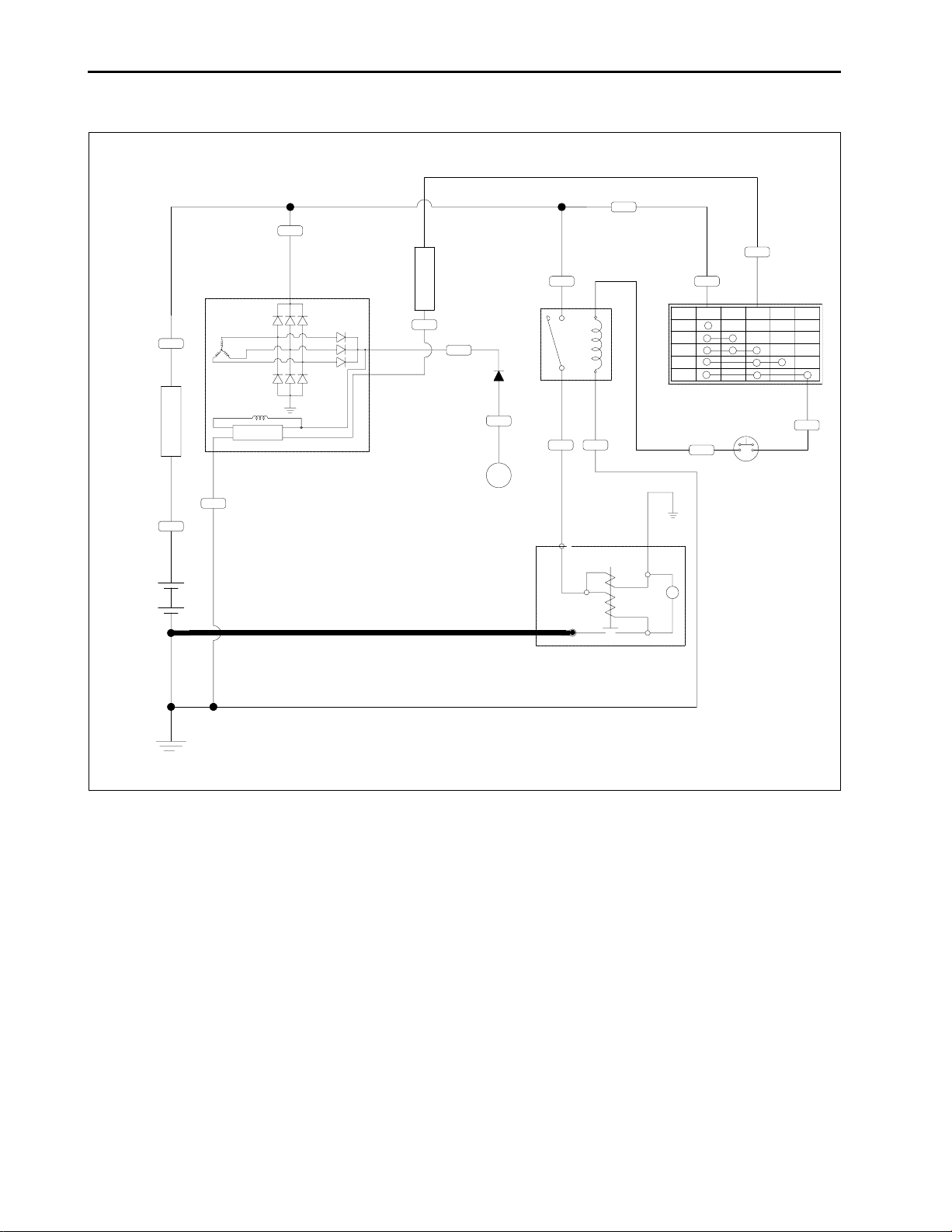
1.3 STARTING SYSTEM
003
5.0R
60A
SLOW BLOW FUSE
5.0R
002
5.0R
BATTERY
5.0R
ALTERNATOR
IC REG
2.0B
001
003
5.0R
009
0.5YL
0.85RW
3.0RW
5 A
103
RLY: STARTER
0.5PB
DIODE(2P)
039
2
3.0R
003
3.0RL
030
0.85B
001
S
003
5.0R
3.0R
003
AM ACC M G
OFF
ACC
ON
GL
SW: MAIN
ST
0.85LB
SW: SAFETY(CLUTCH)
028
M
3.0RW
006
ST
0.85LY
027
When the main key switch is turned to the PREHEAT
position, the terminal AM is connected to the terminal
ON and GL. The glow plugs become red-hot. The preheat indicator lamp also lights while preheating.
When the main switch is turned to the START position
with the safety switch on, the terminal AM is connected
to the terminal ON and ST.
Consequently battery current flows to the starter motor
and start the engine.
The main key switch automatically returns to the ON
position, the terminal AM is connected only to the terminal ACC and ON, thereby causing the starting circuit
to be opened, stopping the starter motor.
When the main key switch is turned from the ON position to the OFF position, the engine stop solenoid
moves the fuel injection pump control rack to the “NO
FUEL” position and stop the engine.
STARTER MOTOR
704WA02A
10-6
D704-WOO Dec. 2004

1.4 CHARGING SYSTEM
ELECTRIC SYSTEM
5.0R
5.0R
003
5.0R
60A
SLOW BLOW FUSE
5.0R
002
5.0R
BATTERY
ALTERNATOR
003
3
3.0R
0.85LB
003
RLY: STARTER
3.0RL
030
0.85LB
0.85B
001
S
STARTER MOTOR
003
5.0R
3.0RW
5.0R
3.0R
003 029
AM ACC M G
OFF
ACC
ON
GL
SW: MAIN
ST
028
3.0RW
006
18
0.85RB
5.0R
ST
0.85LY
027
SW: SAFETY(CLUTCH)
0.85RW
0.85B
M
009
0.5YL
0.85RW
103
3.0RW
006
5.0R
003
3.0RW
5 A
0.85RW
009
0.5WR
026 032
028
PREHEAT CONT.
SIGNAL IN
LAMP
COOLANT TEMP. SENSOR
3
0.85LB
025
ST ON
GND
OUT
0.5GrY
5
RLY: PREHEAT
5 A
0.85R
0.85RB
029
0.85B
001
5.0R
031
5.0BR
5 A
0.85RW
009
ON
008
TIMER RELAY
GND
OUT
1.25L
010
25 A
1.25W
B+
IC REG
2.0B
001
0.5PB
DIODE(2P)
039
0.85B
2
The charging system supplies electric power to various electrical devices. It also charges the battery while
the engine runs.
001
0.85B
PREHEAT PLUG
0.85B
001001
ENG. STOP SOL
0.85B
001
704WA03A
D704-WOO Dec. 2004
10-7
CHAPTER 10 CK25(H)/30(H)
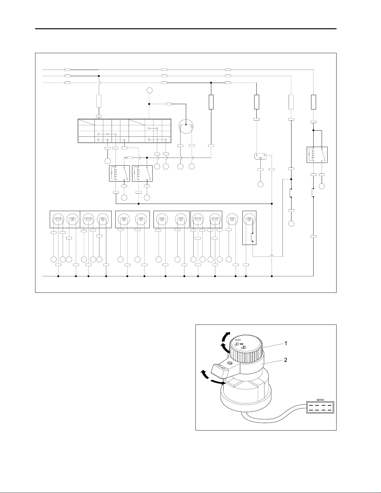
1.5 LIGHTING SYSTEM
ACC
ON
B+
2.0RB
011
3.0RW
006
3.0R
003
TERMINAL
POSITION
OFF
1
2
REAR COMBI LAMP(LH)
21W
STOP5WPOSITION
016
023
0.85BY
0.85B
0.85BrW
16
7
REAR COMBI LAMP(RH)
21W
21W 5W 21W
TURN SIGNAL
023
013
0.85B
0.85BY
0.85B
0.85RW
11
16
GND
016
0.85BrW
7
3.0RW
5A
2.0RY
015
TURN SIGNALPOSITIONSTOP
014
0.85GW
12
10
COMBINATION SWITCH
TB1
1
POSITION
1
B2
TERMINAL
2
OFF
2
0.5Br
018
017
016
0.85BrW
7
RLY: LOW BEAM
0.85B
004
0.5Or
2.0G
0.5B
001
1.25W
8
FRT COMBI LAMP(LH)
21W
TURN SIGNAL5WPOSITION
013
0.85B
0.85RW
11
0.5B
001
016
0.85BrW
7
2.0G
020019
1.25Br
9
0.85B
2.0RB
011
3.0RW
006
3.0R
003
1.25L
012
HAZARD
WARNING
1.25L
SWITCH
RL
014
21W
0.85GW
014
12
0.85B
013
0.85RW
11
5W
016
0.85BrW
7
0.85B
0.85GW
12
LOW
019014
1.25W
8
0.85RW
013
11
RLY: HIGH BEAM
FRT COMBI LAMP(RH)
TURN SIGNAL POSITION
0.85GW
12
3.0R
20A
004
2.0G
HEAD LIGHT
35W/35W
35W/35W
HIGH
LOWHIGH
019
020
001
001
1.25W
1.25Br
2.0B
9
8
2.0B
020
1.25Br
9
2.0RB
011
3.0RW
006
3.0R
003
10W 21W
035
0.85Y
0.85B
13
3.0R
25A
1.25W
008
FLASHER
1.25W
UNIT
B
E
L
001
012
1.25L
10
BACK UP LAMP
WORKING LAMP
SW
0.85B
001001001001001001001001001001001001
1.25B
3.0RW
5 A
0.85RG
034
RLY: STOP
034
0.85RG
SW: BACK UP
0.85Y
035
13
2.0RB
10A
0.85YR
021
0.85YR
0.85YR
0.85BR
0.85BY
022
023
16
SW: STOP LAMP
0.85B
001
704WA04A
The lighting system consists of combination switch, hazard warning switch, flasher unit, stop lamp relay, stop
switch, head lights, turn signal lamps, tail lamps and stop lamps.
A . COMBINA TION SWITCH
The light switch is located on the left-hand side of the
dash.
The three position of the light switch are;
OFF
Taillight/Headlight (low-beam)
Headlights (high beam)
When the switch is in the “Headlights (high beam)”
position, the blue indicator will light.
704WA05A
(1) Head Light Switch
(2) Turn Signal Light Switch
10-8
D704-WOO Dec. 2004
B. HAZARD W ARNING SWITCH
The hazard light switch is a push-pull type switch located on the left-hand side of the dash below the main
light switch. The two positions of the hazard light switch
are;
OFF(Push)
ON (Pull)
When the hazard light switch is in the “ON” position,
the turn signal symbol located in combination meter
will illuminate green and flash.
IMPORTANT
• The hazard lights can be activated with the key
switch in the “OFF” position.
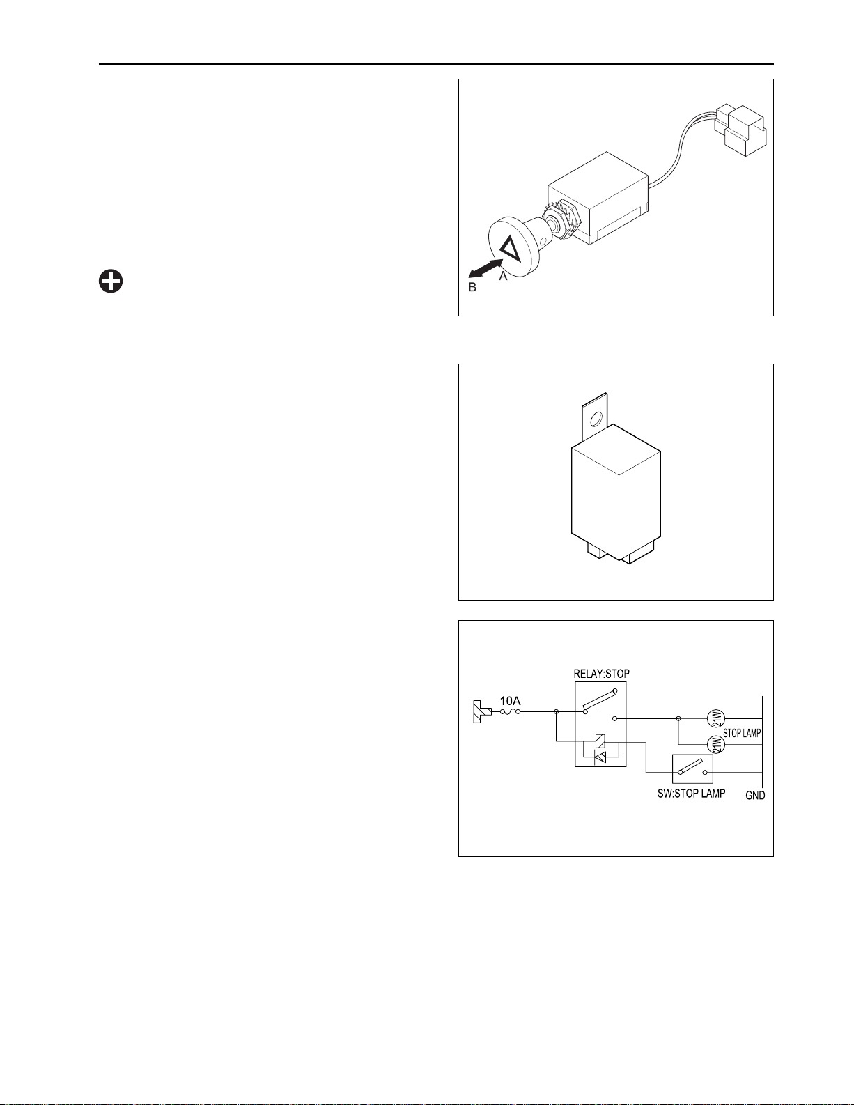
C. FLASHER UNIT
The flasher unit controls the flashing of the hazard
lights. This flasher unit is located under the combination meter.
Control the blinking time of the hazard flasher lamp.
ELECTRIC SYSTEM
704WA06A
(A) OFF (Push) (B) ON (Pull)
D. ST OP AND TAIL LIGHTING COMPONENTS
a. Stop Relay
Relays monitor the current in a circuit. If current is
present, the relay activates a single pole, double throw
switch, causing it to flip over to its other position. The
relays are located under the combination meter.
704WA07A
704WA08A
D704-WOO Dec. 2004
10-9
CHAPTER 10 CK25(H)/30(H)
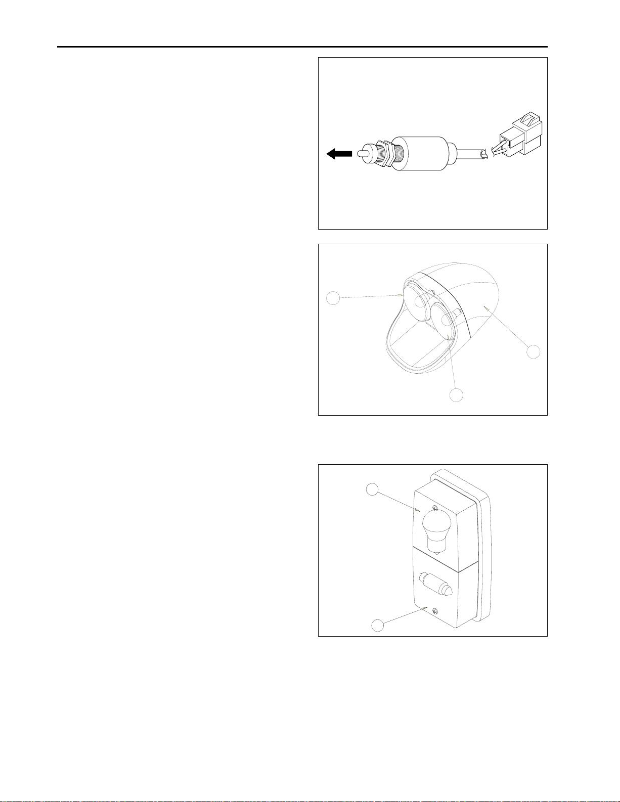
b. Stop Switch
Depressing the brake pedal switches the stop switch
off and the signal will be sent to stop the relay. This
switch is a normally closed type.
c. Stop Lights
When the operator pushes the brake pedal, these lights
will be illuminated.
It gives the information of the stop to following vehicle.
Rated watt of the bulb is 12 V 21 W. Use only the rated
watt of the bulb.
704WA09A
2
d. Tail Light
This lights only operates while the main light switch is
switched to “Tail light/head light”.
1
3
704WA10A
(1 ) Rear Lamp Cover (LH) ( 3) Stop Light / Tail Light
(2) Turn Signal Lamp
2
1
704WA1 1A
10-10
(1 ) Tail light (2 ) Turn Signal Lamp
D704-WOO Dec. 2004
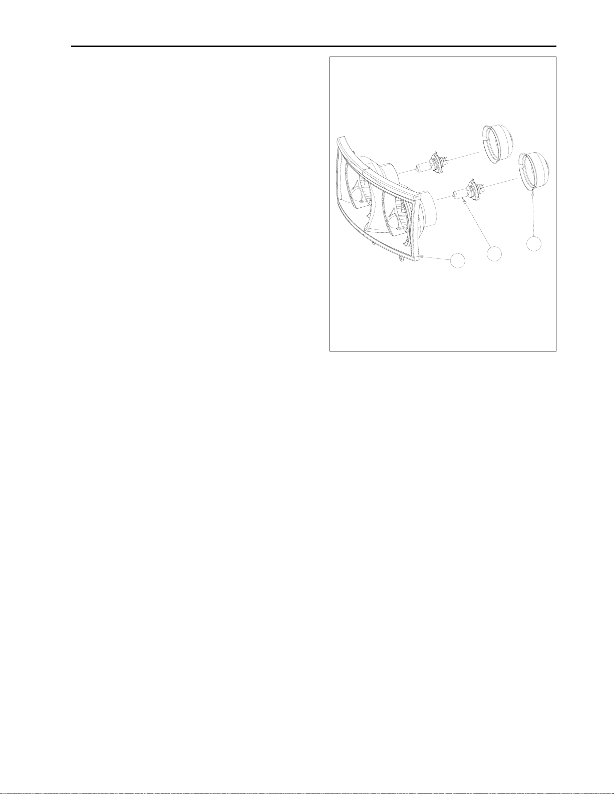
e. Head Lights
This head lights help to make possible to drive during
the night time.
CK25/30-USA/AU
This head lights have 12 V 35 / 35 W bulbs.
Use only same capacity bulb.
CK25/30-EU
This head lights have 12 V 55 / 60 W bulbs.
Use only same capacity bulb.
ELECTRIC SYSTEM
3
1
2
704WA12A
(1) Head Lamp Ass’y (3) Rubber Cover
(2) Bulb
D704-WOO Dec. 2004
10-11
 Loading...