

Page 1
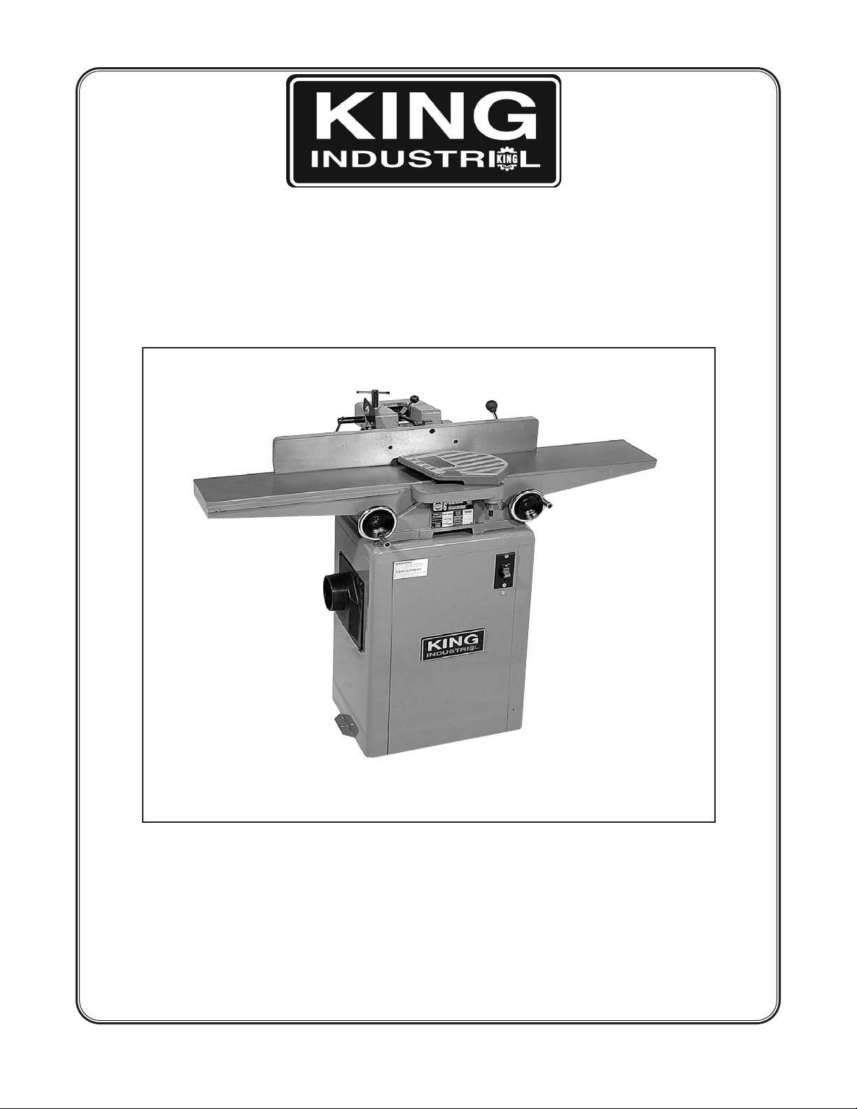
6’’ WOODWORKING
JOINTER
MODEL: KC-60FX
INSTRUCTION MANUAL
COPYRIGHT 2000 BY KING CANADA TOOLS INC.
Page 2

GENERAL SAFETY RULES
WWAARRNNIINNGG:
and have understood all instructions, rules ect. contained in this manual.
Failure to comply can result in accidents involving fire, electric shock,
or personal injury. Keep owners manual and review frequently for
continuous safe operation.
1. KNOW YOUR MACHINE.
For your own safety, read the owner’s manual cafefully. Learn its application and limitations
as well as specific potential hazards pertinent to this machine.
2. GUARD AGAINST ELECTRICAL SHOCK BY PREVENTING BODY CONTACT
WITH GROUNED SURFACES.
3. REMOVE ADJUSTING KEYS AND WRENCHES.
Form a habit of checking to see that keys and wrenches are removed from
the machine before turning it on.
4. KEEP WORK AREA CLEAN.
Cluttered areas invite accidents.
5. DO NOT USE IN DANGEROUS ENVIRONMENTS.
Do not use power tools in damp or wet locations, or expose them to rain. Keep work
areas well illuminated.
:
Do not attempt to operate until you have read thouroughly
6. KEEP CHILDREN AWAY.
All visitors should be kept at a safe distance from work area.
7. MAKE WORKSHOP CHILDPROOF.
With padlocks, master switches, or by removing starter keys.
8. DO NOT FORCE THE MACHINE.
It will do the job better and be safer at the rate for which it was designed.
9. USE THE RIGHT TOOLS.
Do not force the machine or attachments to do a job for which they were not designed.
10. WEAR PROPER APPAREL.
Avoid loose clothing, gloves, neckties, rings, bracelets, or jewelry which could be
caught in moving parts. Nonslip footwear is recommended. Wear protective hair
covering to contain long hair.
11. ALWAYS WEAR SAFETY GLASSES.
Always use face or dust mask if operation is dusty. Everyday eyeglasses only have
impact resistant lenses. They are NOT safety glasses.
12. SECURE WORK.
Use clamps or a vise to hold work when practical. It is safer than using your hand
and frees both hands to operate the machine.
Page 3

13. DO NOT OVERREACH.
Keep proper footing and balance at all times.
14. MAINTAIN MACHINE IN TOP CONDITION.
Keep machine clean for best and safest performance. Follow instructions for
lubricating and changing accessories.
15. DISCONNECT THE MACHINE FROM POWER SOURCE.
Before servicing and when changing accessories, or when mounting and
remounting motor.
16. USE RECOMMENDED ACCESSORIES
Consult the owners manual for recommended accessories.
17. CHECK DAMAGED PARTS.
Before further use of the machine, the guards and other parts should be carefully
inspected to ensure it will operate properly and perform its intended function.
Check for alignment of moving parts, binding of moving parts, mounting, and any other
condition that may affect its operation. Guards and other parts that are damaged
should be properly repaired or replaced.
18. NEVER LEAVE THE MACHINE RUNNING UNATTENDED.
SAFETY RULES FOR JOINTERS
1. KEEP cutterhead sharp and free of all rust and pitch.
2. ALWAYS use a push block when jointing stock that does not give reasonable distance
of safety for your hands.
3. NEVER pass hands directly over the cutterhead.
4. ALWAYS make sure exposed cutterhead behind the fence is guarded, especially
when jointing near the edge.
5. DO NOT perform jointing or planing operations on material shorter than 8 inches,
narrower than 3/4 inch, or thinner than 1/2 inch.
6. MAINTAIN the proper relationship between the infeed and outfeed table surfaces and
cutterhead knife path.
7. SUPPORT the workpiece adequately at all times during operation, maintain
control of the work at all times.
8. DO NOT back the workpiece towards the infeed table.
9. DO NOT attempt to perform abnormal or little-used operations without study and use
of adequate holddown/push blocks, jigs, fixtures, stops, etc..
10. DO NOT make cuts deeper than 1/8’’ in a single pass. On cuts more than 1/2’’ wide,
adjust depth of cut to 1/16’’ or less to avoid wood tearing.
Page 4

UNPACKING THE MACHINE
1. Cafefully unpack the machine.
2. Check to see if there is any damage which occured to the machine during transportation.
Report to your local distributor if there is damage.
3. Check to see if there are any parts missing. If so, contact your local distributor.
CLEANING THE MACHINE
1. The machine has been coated with a rust protection oil for transportation purposes.
2. Thoroughly remove the oil coating after unpacking the machine.
3. Use kerosene to remove the oil coating. Do not use gasoline or paint thinner to remove
the oil coating, as this may damage the painted surfaces.
Page 5
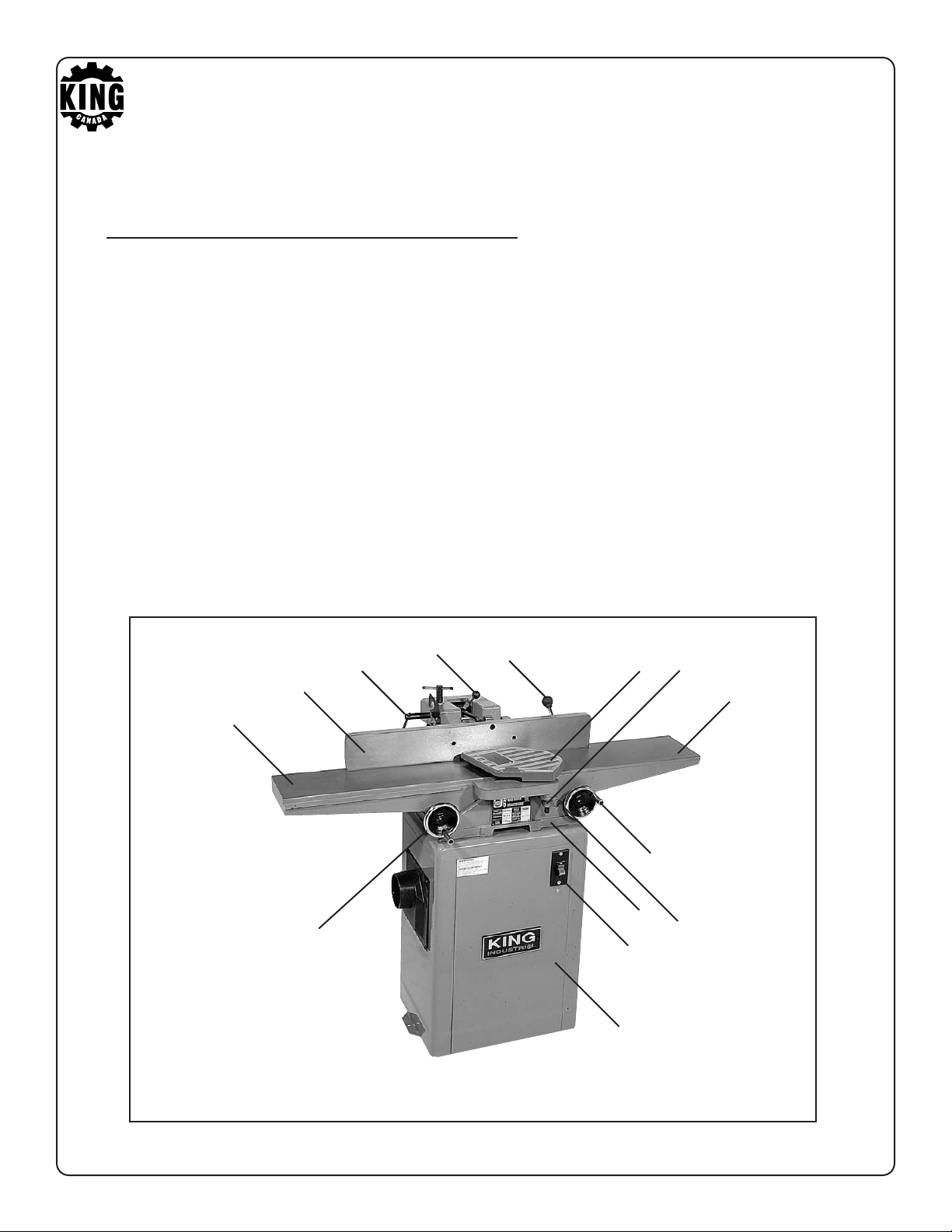
LEGEND OF THE MACHINE
1. Outfeed Table Adjustment Handwheel.
2. Outfeed Table.
3. Fence.
4. Fence Movement Fix Lever.
5. Fence Angle Adjustment Lever.
6. Depth Scale.
7. Lever.
8. Cutterhead Guard.
9. Spring Knob.
10. Infeed Table.
11. Infeed Table Adjustment Handwheel.
12. Base.
13. Power Switch.
14. Enclosed Floor Stand.
5
4
3
2
1
7
14
13
8
12
9
10
11
6
Page 6

SPECIFICATIONS
Cutting Capacity Width...................................6-1/8’’ (155mm)
Cutting Capacity Depth......................................1/2’’ (12.7mm)
Rabbeting Capacity.............................................1/2’’ (12.7mm)
Cutterhead:
Cutterhead Speed.................................................5,000 R.P.M.
Cuts per Minute..............................................................15,000
Number of Knives....................................................................3
Diameter................................................................2.4’’ (61mm)
Table:
Dimensions...............................7.3’’ (185mm) X 45’’ (1143mm)
Height................................................................32.3’’ (820mm)
Fence:
Dimensions...................................4’’ (102mm) X 28’’ (710mm)
Tilts Right..............................................................................45
Positive Stops................................................................900, 45
Overall Dimensions:
Length.................................................................45’’ (1143mm)
Height............Enclosed Steel Stand.................36.6’’ (930mm)
Net Weight......................................................198 lbs. (90 kgs)
0
0
Page 7
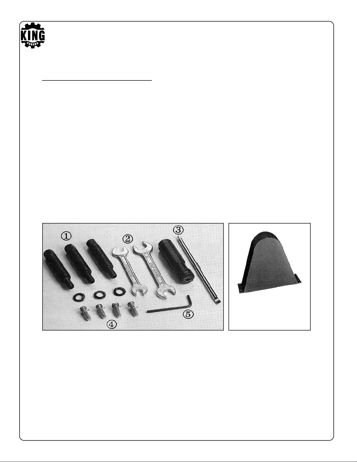
LOOSE PARTS BAG
1. Stand Mounting Screws with Washers................................3 pcs.
2. Open End Wrench...........................8 X10 (1 pc.), 12 X14 (1 pc.)
3. Screwdriver............................................................................1 pc.
4. Belt Guard Lock Screw...................................1/4’’ X 3/4’’ (4 pcs.)
5. Allen Wrench............................................................3mm (1 pc.)
6. Belt Guard..........................................................................1 pc.
6
Page 8
POWER CONNECTIONS
Set aside an electrical circuit that is used exclusively for tools. It should be at least a #12 wire
and protected with a 15 AMP time lag fuse. Before connecting the motor to the power source,
make sure that the voltage is the same as indicated on the machine, and that the machine is
turned off. Check all connections for good contact.
insufficient voltage, damage to the motor may occur.
WARNING: If the machine runs on
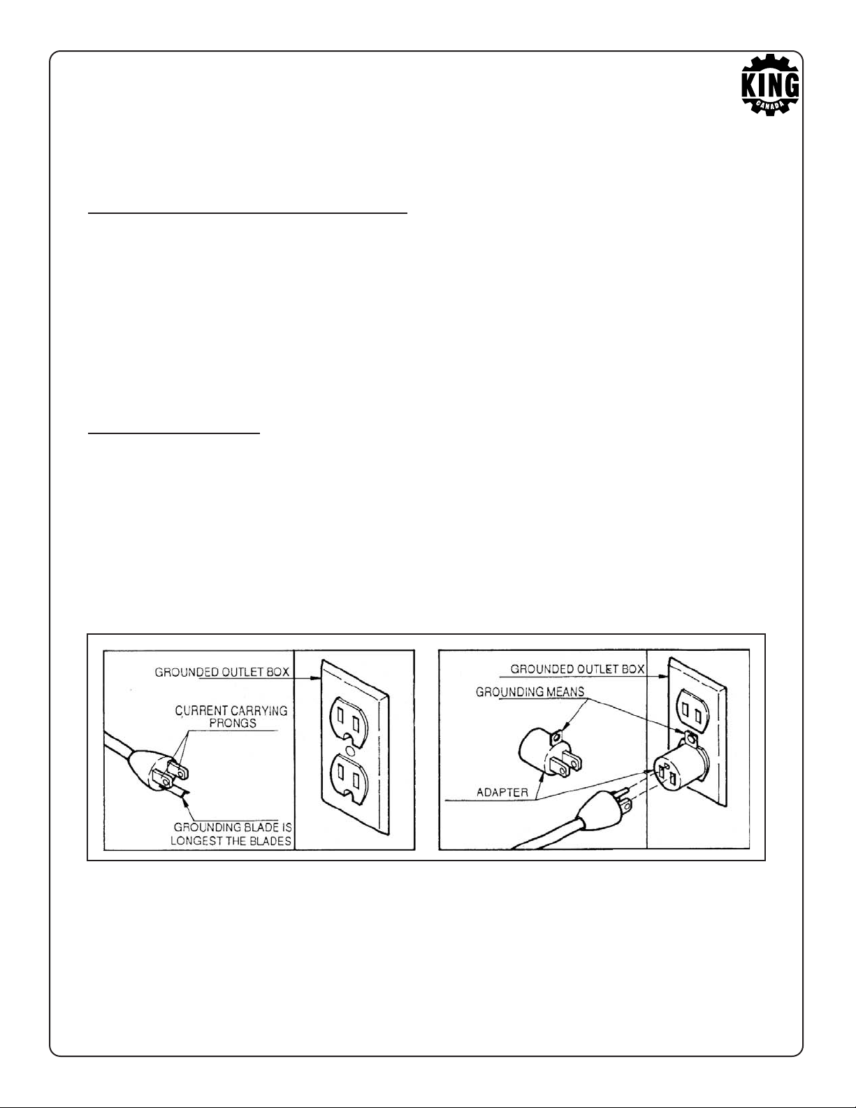
GROUNDING
Failure to adequately ground the machine may result in electric shock to the operator. Always
use a three prong extension cord and outlet. If there is any doubt that the outlet is not grounded
properly, have it checked by a certified electrician. Only use three to two adapters temporarily.
Page 9
EXTENSION CORDS
Check the condition of the extension cord regularly. Use a three wire extension cord with a
three prong plug, and make sure it is plugged into an appropriate three hole receptacle. If you
must use a two prong adapter temporarily, make sure the grounding extension on the adapter
is connected to a permanent ground. Do not bend the grounding plug to fit it into a two hole
receptacle. Remember to use a cord heavy enough to carry the jointer’s current. If the cord
length is under 25 feet for 110V operation, and under 50 feet for 220V operation, use at least
a 14 AWG gauge extension cord. If the cord length is between 25 and 50 feet for 110V
operation, and between 50 and 100 feet for 220V, use at least a 12 AWG gauge extension cord.
Do not use cords longer than 50 feet and 100 feet for 110V and 220V operations respectively.
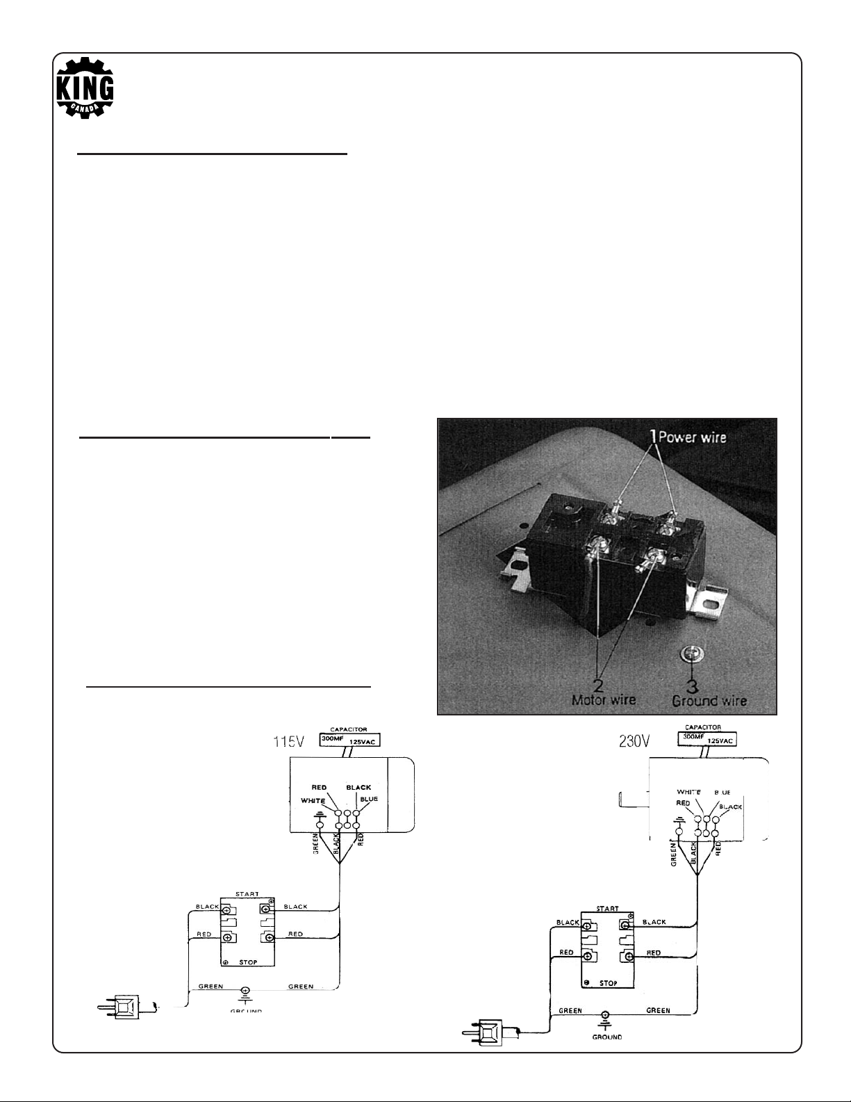
CHANGING VOLTAGE
This machine is set up at the factory for 110V
use. To change the voltage to 220V, disconnect
the machine from its power source and follow
the electrical diagram as shown below.
SWITCH WIRING DIAGRAM
Page 10

STARTING AND STOPPING
THE JOINTER
1. The machine switch is located at the right
side of the machine.
2. Press the ‘ON’ switch to start the machine.
3. Press the ‘OFF’ switch to stop the machine.
DEPTH OF CUT
ADJUSTMENT
1. To set the depth of cut, move the infeed table
up and down.
2. The table can be moved by turning the
depth adjustment handwheel (A) under
the table.
3. Loosen the outfeed table position fix lever
before turning the depth adjustment
handwheel (A). Tighten the infeed table
position lock fix lever (B) after the infeed
table is adjusted.
4. The depth of cut adjustment can be read
on the depth scale (C), located at the
front of the infeed table.
DEPTH ADJUSTMENT HANDWHEEL (A)
DEPTH SCALE (C)
FIX LEVER (B)
Page 11

DEPTH OF CUT LIMIT
1. Never cut to a depth of more than 1/8 of an inch in a single feed.
2. The infeed table is fitted with a depth limit guard (A) to prevent cuts exceeding 1/8 of
an inch.
3. The lock lever (B) will engage when the depth of the cut exceeds 1/8 of an inch.
4. Before moving the infeed table, pull out the lock lever (B) to disengage it.
Page 12

MOUNTING THE JOINTER ONTO THE STAND
1. The stand top has been predrilled with three holes for fastening the jointer onto the
enclosed stand.
2. The infeed end of the jointer should be fastened to the front two holes (A) of the stand.
3. The outfeed end of the jointer should be fastened to the rear single hole (B) of the
stand.
4. Tighten the jointer to the stand using the three special bolts (C) furnished with the
machine.
MOUNTING THE MOTOR ONTO THE STAND
Attach the motor to the bottom of the dust chute using the four 5/16’’ bolts (A), flat
washers, and hex nuts. Do not fully tighten the hex nut at this time, because the
motor will need to be adjusted for belt tension.
Page 13

MOUNTING THE FENCE ONTO THE TABLE
1. The fence (A) shall be mounted at the rear side of the table.
2. Before installing the fence, remove the lock nut from the fixing shaft (F).
3. Place the fence on the table and align the slot (C) with the gib (D), then insert the
fixing shaft (F) through the opening (E).
4. Fit the lock nut on the fixing shaft (F).
FIXING SHAFT (F)
SLOT (C)
GIB (D)
SLOT
FENCE (A)
(E)
Page 14

SETTING FENCE AT A 900ANGLE
1. Before adjusting the fence at a 900angle, adjust the positionning of the infeed
table. Adjust the infeed table so that it is parallel with the outfeed table.
2. Loosen the lock lever (A). Move the fence towards the front of the machine so
that it leans on the table.
3. Place a straight edge ruler on the table and against the fence.
4. Verify to see if the fence is at a 900angle to the table.
5. If the fence is not at a 900angle to the table, please use the following instructions;
6. Loosen the stop nut (B), flip the 900set plate (C) and screw in stop bolt (D) and
adjust the fence to a 90
0
angle with your straight edge ruler
7. Replace set plate, unscrew stop bolt until it touches the set plate and tighten the stop
nut (B) after having adjusted the fence at a 90
0
angle.
.
STOP NUT (B)
STOP BOLT (D)
SET PLATE (C)
LOCK LEVER (A)
Page 15

TILTING THE FENCE
1. The fence can be tilted backwards.
2. Unlock lock handle (A). Flip set plate (B) upwards and pull on fence lever (C) to tilt the
fence backward.
0
3. To obtain a 45
the fence. Screw in 45
stop bolt until it touches the fence and secure using hex. nut.
angle, place a precision combination square on the table and against
0
stop bolt (D) and adjust the fence to a 450angle, unscrew
TILTING LEVER (C)
SET PLATE (B)
STOP BOLT (D)
LOCK LEVER (A)
COMBINATION PRECISION SQUARE (C)
Page 16

REPLACING THE KNIVES
!
!
1. Before replacing the knives, be sure to disconnect the machine from the
power source.
2. Remove the cutterhead guard.
3. Loosen the four fixing screws (A) that tighten the knives.
4. Remove the knife (C).
5. Remove the fixing gib (B).
6. Clean all parts and the cutterhead slot before mounting the knives.
7. Fit the fixing gib and fixing screws.
8. Mount the knives. Ensure that the edge of the knife is facing in the correct
direction.
9. Adjust the knife height so that it is 1/16’’ over the cutterhead drum.
10. Tighten the fixing screws securely.
11. Make the height adjustment for the three knives so that they are at the same
height.
12. Make knife adjustments to the outfeed table.
ARNING!
W
The knives are very sharp, care
should be taken when replacing
the knives.
WARNING!
Tighten the knife fixing screws
securely, otherwise a serious
accident may occur.
Page 17

KNIFE HEIGHT ADJUSTMENT
!
1. The knife height should be adjusted so that it is 1/16’’ over the cutterhead drum.
2. Use knife gauge (E) to adjust the knife height. The knife gauge must come in
contact with the knife. To do so, use a hex. key to turn the screw (D) to make
contact with the knife gauge. Tighten the fixing screws (A).
WARNING!
Tighten the fixing screws
securely, otherwise a serious
accident may occur.
Page 18

ADJUSTING THE KNIFE AND OUTFEED TABLE
1. Turn off and unplug the machine.
2. Adjust the height of the rear table until it is 1/16’’ above the cutterhead drum. To
make this adjustment, place a steel gauge (B) on the table, and use a thickness
gauge (A) of 1/16’’ to obtain the correct height.
The knives must not only be adjusted to the same height as the outfeed table, but
they need to be precisely with it. If the knives are not exactly even with the outfeed
table, perform the following.
3. Place the steel gauge across the knife edge and outfeed table.
4. The outfeed table and steel gauge should be at the same height.
5. If the outfeed table and the steel gauge are not at the same height, then adjust
the height of the knives.
6. IMPORTANT: When checking the same height between the knife edges and the
outfeed table, it is important to check both ends of each knife. This will keep the
knives and the outfeed table parallel.
Page 19

ADJUSTING THE KNIFE AND OUTFEED TABLE
7. If the knives are too low, then the worked surface will be slightly curved. (See Figure C).
8. If the knives are too high, then the work will be gouged at the end of the cut. (See Figure D).
9. To check for proper knife adjustment, cut the workpiece about 1/3 of its full length. The
workpiece should be flush with the infeed table and outfeed tables, with no open spaces
under the cut surface. (See Figure E).
FIGURE C
FIGURE D
FIGURE E
Page 20

MOUNTING PULLEY ONTO THE MOTOR
1. Fit the pulley (A) onto the shaft with the hub of
the pulley facing outwards.
2. The key must be inserted into the keyway between
the motor pulley and shaft.
3. Tighten the two set screws on the hub securely.
4. Align the pulleys by using a straight edge.
MOUNTING THE V-BELT
1. This jointer uses a size A-36 V-belt.
2. Before mounting the V-belt, you must align both pulleys. Ensure that the straight
edge press against the sides of both pulleys to make the alignment adjustments.
A
3. Once the pulleys are properly aligned, place the V-belt onto the cutterhead pulley
and motor pulley.
4. Make tension adjustments to the V-belt after the new belt has been installed.
5. Check to see if the V-belt can run freely when turning the V-belt slowly.
CUTTERHEAD PULLEY
V-BELT
WARNING!
Avoid getting fingers caught when
turning the V-belt by hand.
MOTOR PULLEY
Page 21

MOUNTING THE V-BELT GUARD
1. The V-belt guard is mounted at the back of the machine.
2. When installing the V-belt guard, fit it onto the opening at the top of the floor stand.
3. Fit the V-belt guard onto the floor stand and lock it by using the four 1/4’’ screws.
4. After the V-belt guard has been mounted, try to turn the V-belt by hand to ensure
that the V-belt runs freely.
WARNING! Avoid getting fingers caught when turning the V-belt by hand.
Page 22

MOUNTING CUTTERHEAD GUARD
1. Mount the cutterhead guard (A) by inserting the post (B) into the hole on the front of
the infeed table.
2. Turn the knob (C) under the infeed table right, before you fit the cutterhead guard post
through the hole.
3. Make sure that the slot on the cutterhead guard post engages the spring that can be
seen through the hole.
4. Check if the cutterhead gaurd operates normally by shifting the cutterhead guard,
then releasing it. If it is functioning properly, the cutterhead should return completely.
If not, the tension of the spring should be adjusted.
5. If the spring tension is insufficient, lift the cutterhead guard so that it disengages
the spring. Then turn the knob right, to increase the spring tension.
CUTTERHEAD GUARD (A)
POST (B)
KNOB (C)
Page 23

ADJUST THE V-BELT TENSION
1. The correct belt tension can be identified by pressing the belt with your finger using
normal pressure. The belt should yield 1/2’’ when pressed.
2. When belt tension adjustment is necessary, loosen the four lock nuts on the dust chute.
Move the motor vertically until proper tension is obtained.
3. Tighten the four lock nuts after the belt tension has been adjusted.
1/2’’
MOTOR
PULLEY
Page 24

ADJUSTING THE GIBS
1. After the machine has been operating for a long period, the gibs may become loose.
At this time, you need to adjust the gibs.
2. Loosen the three infeed table lock nuts (A) and the two outfeed table lock nuts (B).
3. Adjust the three gib screws (C) on the infeed table and the two gib adjust screws (D)
on the outfeed table until smooth infeed table traverse is found.
4. Properly tighten all lock nuts, tightening the upper ones first and then the lower ones.
INFEED T
INFEED TABLE GIB ADJUSTMENT
SCREW (C).
ABLE LOCK NUT (A).
OUTFEED TABLE LOCK NUT (B).
OUTFEED TABLE GIB ADJUSTMENT
SCREW (D).
Page 25

ATTACHING DUST CHUTE (OPTIONAL)
TO ENCLOSED STAND
When the machine is furnished with a 4’’ dust chute, it should be connected to the
enclosed stand as shown in the illustration below. Tighten the dust chute (A) to the
enclosed stand (B) with the four lock screws (C).
CAUTION!
The dust chute should be used in
conjunction with a dust collector,
otherwise the dust may collect inside
the machine.
Page 26

JOINTING AND PLANING OPERATIONS
Jointing Operations
In order to square the edge of the workpiece, use a jointing cut. Set the depth of cut to
approximately 1/8’’, and adjust the fence so that it is square with the table. Place the work
piece on the jointer with the narrow edge on the infeed table and the flat surface against the
fence (See below). Move the workpiece from the infeed table to the outfeed table, taking it
across the cutterhead as you go. As the workpiece enters the outfeed table, maintain
enough pressure so that the cut surface stays in close contact with the table. The workpiece
needs to stay in contact with the fence at all times.
Planing Operations
In order to plane the wider flat surface of a workpiece, use the same techniques as for
jointing operations, but with the wider, flat surface on the infeed table, and the narrow
edge against the fence (See below). Move the workpiece across the cutterhead,
maintaining adequate pressure so that the workpiece stays in contact with the fence
and table.
WARNING
Always use push blocks when executing planing operations, otherwise serious injury may occur.
Page 27

Rabbet Cuts
1. Remove the cutterhead guard.
2. Move the fence to the desired width of the rabbet. (The distance from the edge of the
knives to the fence).
3. Set the infeed table to the desired depth of cut.
4. Run the workpiece over the cutterhead, applying even pressure.
5. For deep rabbet cuts, this process may be repeated several times in succession until
the desired depth is achieved.
Page 28

SIMPLE PUSH STICK
1. The simple push stick can be made by the user of the machine. Make the simple push
stick as shown below.
2. When undertaking planing operations, ensure the lid of the simple push stick catches the
tail edge of the workpiece. This will maintain adequate pressure so that the workpiece
staypin will keep in contact with the fence and table.
PUSH BLOCK
This is the suggested type of push block which can be purchased from your local
KING CANADA distributor.
K-1400
PARTS DIAGRAM & PARTS LISTS
Refer to the Parts section of the King Canada web site for the most updated parts
diagram and parts list.
 Loading...