

Page 1

Line Interruption
01/2017
17” LONG STROKE DRILL PRESS
WITH SAFETY GUARD
INSTRUCTION MANUAL
COPYRIGHT © 2016 ALL RIGHTS RESERVED BY KING CANADA TOOLS INC.
MODEL: KC-119FC-LS
Page 2

WARRANTY INFORMATION
2-YEAR
LIMITED WARRANTY
FOR THIS 17” DRILL PRESS
OFFERS A 2-YEAR LIMITED WARRANTY
KING CANADA TOOLS
FOR NON-COMMERCIAL USE.
PROOF OF PURCHASE
Please keep your dated proof of purchase for warranty and servicing purposes.
REPLACEMENT PARTS
Replacement parts for this product are available at our authorized King Canada service centers across Canada.
LIMITED TOOL WARRANTY
King Canada makes every effort to ensure that this product meets high quality and durability standards. King Canada warrants to the
original retail consumer a 2-year limited warranty as of the date the product was purchased at retail and that each product is free from
defects in materials. Warranty does not apply to defects due directly or indirectly to misuse, abuse, normal wear and tear, negligence or
accidents, repairs done by an unauthorized service center, alterations and lack of maintenance. King Canada shall in no event be liable
for death, injuries to persons or property or for incidental, special or consequential damages arising from the use of our products.
To take advantage of this limited warranty, return the product at your expense together with your dated proof of purshase to an authorized
King Canada service center. Contact your retailer or visit our web site at www.kingcanada.com for an updated listing of our authorized
service centers. In cooperation with our authorized serviced center, King Canada will either repair or replace the product if any part or
parts covered under this warranty which examination proves to be defective in workmanship or material during the warranty period.
NOTE TO USER
This instruction manual is meant to serve as a guide only. Specifications and references are subject to change without prior notice.
PARTS DIAGRAM & PARTS LISTS
Refer to the Parts section of the King Canada web site for the most updated parts diagram and parts list.
KING CANADA INC. DORVAL, QUÉBEC, CANADA H9P 2Y4
www.kingcanada.com
Page 3

GENERAL SAFETY INSTRUCTIONS
FOR POWER TOOLS
1. KNOW YOUR TOOL
Read and understand the owners manual and labels affixed to the
tool. Learn its application and limitations as well as its specific potential hazards.
2. GROUND THE TOOL.
This tool is equipped with an approved 3-conductor cord and a 3prong grounding type plug to fit the proper grounding type receptacle. The green conductor in the cord is the grounding wire.
NEVER connect the green wire to a live terminal.
3. KEEP GUARDS IN PLACE.
Keep in good working order, properly adjusted and aligned.
4. REMOVE ADJUSTING KEYS AND WRENCHES.
Form habit of checking to see that keys and adjusting wrenches
are removed from tool before turning it on.
5. KEEP WORK AREA CLEAN.
Cluttered areas and benches invite accidents. Make sure the floor
is clean and not slippery due to wax and sawdust build-up.
6. AVOID DANGEROUS ENVIRONMENT.
Don’t use power tools in damp or wet locations or expose them to
rain. Keep work area well lit and provide adequate surrounding
work space.
7. KEEP CHILDREN AWAY.
All visitors should be kept a safe distance from work area.
8. MAKE WORKSHOP CHILD-PROOF.
-with padlocks, master switches or by removing starter keys.
9. USE PROPER SPEED.
A tool will do a better and safer job when operated at the proper
speed.
10. USE RIGHT TOOL.
Don’t force the tool or the attachment to do a job for which it was
not designed.
11. WEAR PROPER APPAREL.
Do not wear loose clothing, gloves, neckties or jewelry (rings,
watch) because they could get caught in moving parts. Non-slip
footwear is recommended. Wear protective hair covering to contain long hair. Roll up long sleeves above the elbows.
12. ALWAYS WEAR SAFETY GLASSES.
Always wear safety glasses (ANSI Z87.1). Everyday eye-glasses
only have impact resistant lenses, thet are NOT safety glasses.
Also use a face or dust mask if cutting operation is dusty.
13. DON’T OVERREACH.
Keep proper footing and balance at all times.
14. MAINTAIN TOOL WITH CARE.
Keep tools sharp and clean for best and safest performance. Follow
instructions for lubricating and changing accessories.
15. DISCONNECT TOOLS.
Before servicing, when changing accessories or attachments.
16. AVOID ACCIDENTAL STARTING.
Make sure the swich is in the ‘’OFF’’ position before plugging in.
17. USE RECOMMENDED ACCESSORIES.
Consult the manual for recommended accessories. Follow the instructions that accompany the accessories. The use of improper
accessories may cause hazards.
18. NEVER STAND ON TOOL.
Serious injury could occur if the tool tips over. Do not store materials such that it is necessary to stand on the tool to reach them.
19. CHECK DAMAGED PARTS.
Before further use of the tool, a guard or other parts that are
damaged should be carefully checked to ensure that they will operate properly and perform their intended function. Check for alignment of moving parts, breakage of parts, mounting, and any other
conditions that may affect its operation. A guard or other parts that
are da -maged should be properly repaired or replaced.
20. NEVER LEAVE MACHINE RUNNING
UNATTENDED.
Turn power ‘’OFF’’. Don’t leave any tool running until it comes to a
complete stop.
SPECIFIC SAFETY INSTRUCTIONS FOR DRILL PRESS
1. TO AVOID INJURY FROM PARTS BEING THROWN BY
THE SPRING
Follow the instructions exactly as given and shown in “Adjusting
the quill return spring”.
2. USING A DRILL PRESS VISE
When using a drill press vise, always fasten it to the table.
3. NEVER DO “FREEHAND WORK”
Never do any work “Freehand” (hand holding the workpiece rather
than supporting it on the table) except when you have polishing to
do.
4. SECURE the lock head to the column, table support to column
and table to table support before operating the drill press.
5. NEVER move the head or table while the drill press is running.
6. USE THE RECOMMENDED SPINDLE SPEED for the
specific operation and workpiece material. Check the panel inside
the guard cover for drill information. For accessories, use the instructions provided with the accessories.
7. NEVER climb on the drill press table, it could break or pull the en-
tire drill press down on you.
Page 4
ELECTRICAL INFORMATION
WARNING
ALL ELECTRICAL CONNECTIONS MUST BE DONE BY A QUALIFIED ELECTRICIAN. FAILURE TO COMPLY MAY RESULT IN SERIOUS
INJURY! ALL ADJUSTMENTS OR REPAIRS MUST BE DONE WITH THE MACHINE DISCONNECTED FROM THE POWER SOURCE.
FAILURE TO COMPLY MAY RESULT IN SERIOUS INJURY!
POWER SUPPLY
WARNING: YOUR DRILL PRESS MUST BE CONNECTED TO A 120V
WALL OUTLET, WITH A MINIMUM 15-AMP. BRANCH CIRCUIT AND USE
A 15-AMP TIME DELAY FUSE OR CIRCUIT BREAKER. FAILURE TO
CONNECT IN THIS WAY CAN RESULT IN INJURY FROM SHOCK OR
FIRE.
GROUNDING
Your drill press must be properly grounded. Not all outlets are properly
grounded. If you are not sure if your outlet is properly grounded, have it
checked by a qualified electrician.
WARNING: IF NOT PROPERLY GROUNDED, THIS DRILL PRESS CAN
CAUSE ELECTRICAL SHOCK, PARTICULARLY WHEN USED IN DAMP
LOCATIONS. TO AVOID SHOCK OR FIRE, IF THE POWER CORD IS
WORN OR DAMAGED IN ANY WAY, HAVE IT REPLACED IMMEDIATELY.
If this drill press should malfunction or breakdown, grounding provides a
path of least resistance for electric current, to reduce the risk of electric
shock. This drill press is equipped with a cord having an equipment-grounding conductor and grounding plug. The plug must be plugged into an appropriate outlet that is properly installed and grounded in accordance with all
local codes and ordinances.
WARNING: TO MAINTAIN PROPER GROUNDING, DO NOT REMOVE OR
ALTER THE GROUNDING PRONG IN ANY MANNER.
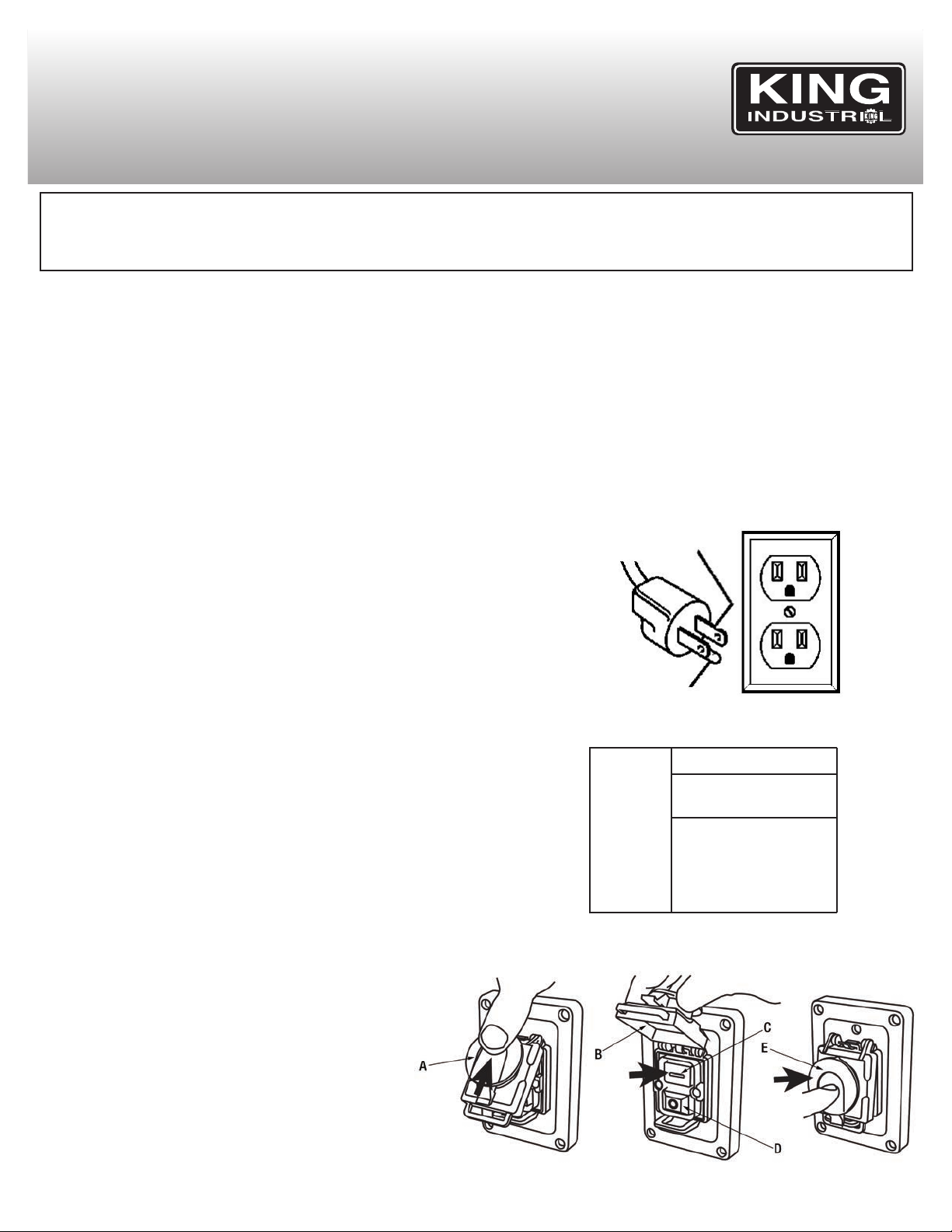
120V OPERATION
As received from the factory, your drill press is ready to run for 120V
operation. This machine is intended for use on a circuit that has an outlet
and a plug which looks like the one illustrated in Fig.1.
WARNING: DO NOT USE A TWO-PRONG ADAPTOR(S) FOR THEY ARE
NOT IN ACCORDANCE WITH LOCAL CODES AND ORDINANCES.
NEVER USE IN CANADA.
EXTENSION CORDS
The use of any extension cord will cause some loss of power. If you do not
have a choice, use the table in Fig.2 to determine the minimum
wire size (A.W.G-American Wire Gauge) extension cord
needed. Use only 3-wire extension cords which have 3-prong
grounding type plugs and 3-hole receptacles which accept the
tool’s plug.
TURNING THE DRILLPRESS ON/OFF
This Drill Press comes with a 2 step activation safety switch, refer
to Fig.3, which starts and stops the machine. To turn the Drill Press
on;
1. Push up on the emergency stop button (A) Fig.3 and lift the switch
cover (B) upwards as shown.
2. Press the green On button (C) to start the Drill Press.
3. To stop the Drill Press, you can either press the red Off button (D)
or lower the switch cover and push the large emergency stop button (E).
PROPERLY GROUNDED OUTLET
CURRENT CARRYING
PRONGS
GROUNDING
PRONG
Figure 1
Tool’s
Amperage
Rating
3-6
6-8
8-10
10-12
12-16
Cord Size in A.W.G.
Cord Length in Feet
25 50 100 150
18 16 16 14
18 16 14 12
18 16 14 12
18 16 14 12
14 12 - -
Figure 2
For circuits that are further away from the electrical circuit box,
the wire size must be increased proportionately in order to deliver ample voltage to the drill press motor. Refer to Fig.2 for
wire length and size.
Figure 3
Page 5

GETTING TO KNOW YOUR DRILL PRESS
1. Cast-iron base.
2. Table lock handle.
3. Tilting table.
4. 3/4” chuck.
5. Limit switch safety guard.
6. 2 step activation safety switch.
7. Pulley cover.
8. Motor belt tension lever.
9. Head locking set screws (2)
10. Dual laser attachment.
11. Feed handle (1 of 3)
12. Column and rack
13. Table raising/lowering handle
14. Bevel angle scale
15. Safety guard lock knob
16. Dual laser attachment switch
17. Spring return
18. Depth stop rod with depth scale
19. Table support lock handle
20. Column and rack locking collar
21. Locking set screw (1 of 2)
FIGURE 4
SPECIFICATIONS
MODEL..............................................................................................................................................................................KC-119FC-LS
VOLTAGE ....................................................................................................................................................110V/220V (prewired 110V)
AMPS ..................................................................................................................................................................................12.5A/6.25A
MOTOR R.P.M.................................................................................................................................................................................1725
Hz/PHASE....................................................................................................................................................................60 Hz / 1 PHASE
CHUCK CAPACITY ..........................................................................................................................................................................3/4”
SWING ....................................................................................................................................................................................16-15/16”
MAX. DISTANCE FROM CHUCK TO THE COLUMN..................................................................................................................8-7/16”
MAX. DISTANCE FROM CHUCK TO THE TABLE......................................................................................................................23-3/4”
MAX. SPINDLE TRAVEL......................................................................................................................................................................6”
NUMBER OF SPEEDS/RANGE OF SPEEDS ........................................................................................................12 (255-2750 RPM)
SPINDLE TAPER ..........................................................................................................................................................................MT#3
WEIGHT ....................................................................................................................................................................................230 LBS
FIGURE 5
Page 6

ASSEMBLY
BASE, COLUMN & TABLE ASSEMBLY
1) Position the base (A) Fig.6 on the floor. Remove the protective
covering and discard.
2) Remove protective sleeve from the column & column support (B) and
discard. Place the column assembly on the base, align the holes in the
column support with the holes in the base.
3) Locate four long hex. bolts from the parts bag.
4) Install a hex. bolt (C) in each hole through the column support and the
base and tighten with the ajustable wrench.
FIGURE 6
5) Loosen pan head screw (A) Fig.7 in column collar (B) using a Phillips
screwdriver and then remove collar (B) and rack (C) from the column.
6) Slide rack (A) Fig.8 down through the large round opening in the table
support (B). Engage rack in gear mechanism found inside the
opening of the table support.
7) While holding the rack (A) Fig.8 and table support (B) in an engaged
position, slide both down over the column (C). Slide rack down the column until the rack is positioned against the lower column support (D).
8) Replace column collar (B) Fig.7 and position it bevel side down over
the rack (C). Tighten pan head screw (A) in collar. To let the rack slide
when the table is swung to the left or right around the column, the collar must sit loosely over the rack and should not be angled on the column. Only tighten pan head screw enough to keep the collar in place,
otherwise the collar may break due to excessive pressure.
FIGURE 7
FIGURE 8
Page 7

ASSEMBLY
BASE, COLUMN & TABLE ASSEMBLY continued...
9) Locate the crank handle (A) Fig.9 and install it on the worm gear shaft
on the side of the table support. Tighten the hex. bolt (B) on the flat
section of the worm gear shaft.
10) Install the table support lock handle (C) Fig.9 to the table support as
shown.
11) Install the table lock handle (A) Fig.10 to the table support (B) as
shown. Do not tighten.
FIGURE 9
12) Slide the table (C) Fig.10 into the opening of the table support.
Tighten table lock handle (A).
INSTALLINGTHEHEAD
Warning! The drill press head is very heavy, it is not recommended to
attempt installation of the head by yourself, obtain help.
1) Carefully lift the head (A) Fig.11 above the column (B) and slide it down
on the column as far as it will go. Align the head with the table and the
base.
2) Using a 5 mm hex. key, tighten both head set screws (C) on the right
side of the head.
FIGURE 10
FIGURE 11
Page 8

ASSEMBLY
INSTALLINGPULLEYCOVER KNOB OR LOCKING PULLEY COVER
1) For safety reasons, user may be required to lock the pulley cover (B)
Fig.12 to prevent easy access to the pulleys. This can be done by using
the small pan head screw (A) which came installed.
2) If safety is less of a concern, you can install the lock knob (C) Fig.12
to the pulley cover (B) instead.
INSTALLING THE FEED HANDLES
1) Locate the three feed handles (A) Fig.13 among the loose parts.
2) Screw the feed handle tightly into the threaded holes in the hub (B).
FIGURE 12
INSTALLING AND USING THE LIMIT SWITCH PROTECTED
SAFETY GUARD
The limit switch safety guard is intended to protect the operator during
drilling operations. If the safety guard is not positioned in its closed position (in front of the drill chuck), the safety guard limit switch will prevent
the drill press from starting. Close the safety guard and then press the
green On button to start. If the safety guard is opened during a drilling
operation the drill press will shut off automatically, the safety guard will
need to be closed and the green On button will need to be pressed to
restart drill press.
1) Mount the limit switch bracket (A) Fig.14 to the mounting bracket (B)
using 2 pan head screws (C) as shown.
FIGURE 13
FIGURE 14
Page 9

ASSEMBLY & ADJUSTMENTS
INSTALLING AND USING THE LIMIT SWITCH PROTECTED
SAFETY GUARD continued...
2) Remove cap screw (A) Fig.15 from the bar and safety guard assembly
(B).
3) Slide the bar and safety guard assembly (B) up into the limit switch
bracket (C). Reinstall cap screw (A).
4) Adjust the height of the bar and safety guard assembly and secure its
position by tightening lock knob (D).
It is recommended to test the limit switch safety guard before any drilling
operation. Turn drill press on and open the safety guard, the drill press
MUST shut off. If it doesn’t, the safety guard needs to be reinstalled
correctly.
INSTALLING THE CHUCK
1) Locate the 3/4” chuck (A) Fig.16 and arbor (B) in the box of parts.
2) Clean out the tapered hole in the chuck, also clean the arbor nose with
a clean cloth. Make sure there are no foreign particles sticking to the
surfaces. The slightest piece of dirt on the arbor nose or the chuck will
prevent the chuck from seating properly. This will cause the drill to
“wobble”.
FIGURE 15
NOTE: If the tapered hole in the chuck is extremely dirty, use a cleaning
solvent on a clean cloth.
3) Push the chuck up on the arbor nose and arbor nose up into the drill
spindle (C) as far as they will go.
4) Turn the chuck sleeve clockwise and open the chuck jaws com-
pletely.
5) Lightly tap the nose of the chuck with a piece of wood to insure the
proper seating of the chuck on the arbor.
REMOVING THE CHUCK & ARBOR
1) Lower the quill using using the feed handles. Align key holes in spindle
and quill (A) Fig.17 as shown by rotating the chuck (C) by hand.
2) Insert drift key (B) into key holes in the quill.
3) Tap key drift key lightly until the chuck and arbor fall out of the spindle.
NOTE: Place one hand below the chuck to catch it when it falls out.
FIGURE 16
FIGURE 17
Page 10

ASSEMBLY & ADJUSTMENTS
INSTALLING DUAL LASER GUIDE ATTACHMENT
WARNING! Do not look directly at the laser beams. Do not aim
the laser beams at any person or any object other than your
workpiece.
NOTE: This dual laser guide attachment supplied with this drill press is
universal, 4 different mounting brackets are supplied. This allows the user
to install the dual laser guide attachment to this drill press or other drill
presses.
1) Place appropriate mounting bracket (B) Fig.18 and laser attachment
(A) around the column as shown and fix them together using two pan
head screws (C).
2) The dual laser switch (D) is located on the right side of the laser attachement.
3) Slide the battery compartment cover (E) forward and remove it, insert
two AAA batteries (not included) and reposition battery compartment
cover.
4) To adjust the position of the dual lasers, simply turn and move the laser
heads (F) to the desired position.
FIGURE 18
TENSIONING BELTS / SETTING DESIRED DRILLING SPEED
NOTE: The drill press is shipped with the belts installed, but they should
be properly tensioned before use.
1) Lift the guard (A) Fig.19 and keep it opened.
2) Loosen the belt tension set screws (B) located on both sides of the
drill press head. Release tension to the motor belt by turning belt tension handle (C) counterclockwise. The motor pulley (D) can now be
removed.
3) Loosen hex. bolts (A) Fig.20 which secure the centre pulley (B). Slide
pulley to the left to loosen tension on the spindle pulley. The spindle
belt (C) can now be removed.
4) Choose the desired speed for your drilling operation, and move the
spindle and motor belts to the indicated position on the pulleys as indicated in the speed chart below. You can also refer to the speed chart
on the inside of the belt guard Fig.20.
5) Once both belts are positioned on the pulleys, turn the belt tension
handle (C) Fig.19 clockwise to apply tension to the belts.
NOTE: The belts should
pressure at the mid-point of the belts between the pulleys.
6) Retighten hex. bolts (A) Fig.20 to secure centre pulley.
7) Retighten the belt tension set screws (B) Fig.19.
8) Close the belt guard.
9) If the belts slip while drilling, reajust the belt tension.
deflect approximately 1/2” by applying finger
FIGURE 19
FIGURE 20
Page 11

ADJUSTMENTS & OPERATION
ADJUSTING THE TABLE SQUARE TO THE HEAD
1) Insert a precision round steel rod (A) Fig.21 approximately 3” long into
the chuck and tighten.
2) With the table (B) raised to working height and locked into position,
place a combination square (C) flat on the table beside the rod.
3) If an adjustment is necessary, loosen the table bevel lock bolt (A)
Fig.22 with an adjustable wrench and the set screw (B) with a hex.
key. This adjustment is located under the table.
4) Align the table square to the rod by tilting the table.
5) Retighten the table bevel lock bolt and set screw.
TILTING THE TABLE
To use the table in a bevel position, loosen the bevel lock hex. bolt (A)
Fig.22 with an adjustable wrench. Then loosen the set screw (B) with a
hex. key. Tilt the table to the desired angle by reading the bevel scale (C)
on the table support. Retighten the bevel lock bolt and set screw.
FEEDING
Pull down the feed handles with only enough effort to allow the drill to
cut. Feeding too slowly might cause the drill to burn...feeding too rapidly
might stop the motor...cause the belt or drill to slip... tear the workpiece
loose or break the drill bit.
FIGURE 21
HOLE LOCATION
Make an indentation in the workpiece where you want the to drill a hole
using a centre punch or a sharp nail. Before turning the switch ON, bring
the drill bit down to the workpiece, lining it up with the hole location.
POSITIONING THE TABLE AND WORKPIECE
Lock the table to the column in a position so that the tip of the drill is just
a little above the top of the workpiece. Always place a piece of back-up
material (wood, plywood) on the table underneath the workpiece. This
will prevent splintering or making a heavy burr on the underside of the
workpiece as the drill breaks through. To keep the back-up material from
spinning out of control, it must come in contact with the left side of the
column.
WARNING! To prevent the workpiece or the back-up material from being
torn from your hand while drilling, position them against the left side of
the column. If the workpiece or the back-up material are not not long
enough to reach the column, clamp them to the table. Failure to do this
could result in personal injury.
FIGURE 22
Page 12

MAINTENANCE / TROUBLESHOOTING
MAINTENANCE
WARNING! For your own safety, turn the switch “OFF” and remove the
plug from the power source before maintaining or lubricating your drill
press.
• Keep the Drill Press clean and free of dust and debris. Painted surfaces
can be wiped with a damp rag.
• Periodically lubricate all sliding or moving parts including the column and
rack (A & C) Fig.8 and the quill (C) Fig.16 (use any all purpose grease,
available at any hardware store).
• Lightly grease the belt tension slide bars (A) Fig.23 every two months or
as needed depending on frequency of use.
• Bearings in the quill and the V-belt pulleys are sealed and permanently
lubricated – no further lubrication is required.
• Frequently blow out any dust that may accumulate inside the motor. After
operation, remove chips or dirt on the machine and apply a coat of furniture-type paste wax to the table and the column, this will help keep the
surfaces clean and free of rust.
PROBLEM
Noisy operation.
Drill bit burns.
Wood splinters on underside of workpiece.
Workpiece torn loose
from hand.
Drill bit binds in workpiece.
1. Incorrect belt tension.
2. Dry spindle.
3. Loose spindle pulley.
4. Loose motor pulley.
1. Incorrect speed.
2. Chips not comming out of hole.
3. Dull drill bit.
4. Feeding too slow.
5. Not lubricated.
1. No “Back-up material” under the workpiece.
1. Not supported or clamped properly.
1. Workpiece is pinching the drill bit or there
is an excessive feeding pressure.
2. Improper belt tension.
PROBABLE CAUSE
1. Adjust the tension.
2. Lubricate the spindle.
3. Tighten the retaining nut on the pulley as needed.
4. Tighten the set screws which hold the puleys in place.
1. Change the speed.
2. Retract the drill bit frequently to clear the chips.
3. Resharpen the drill bit.
4. Feeding too fast...allow the drill bit to cut.
5. Lubricate the drill bit with cutting or motor oil.
1. Support the workpiece or clamp it.
1. Support the workpiece or clamp it.
1. Support the workpiece or clamp it.
2. Adjust the tension of the belt.
FIGURE 23
SOLUTION
Excessive drill bit
wobbling.
Quill returns too fast or
too slow.
Chuck will not stay attached to the spindle. It
falls off when trying to
install it.
1. Bent drill bit.
2. Worn spindle bearings.
3. Drill bit is not properly installed in the
chuck.
4. Chuck not properly installed.
1. Spring has improper tension.
1. Dirt, grease or oil on the tapered inside
surface of the chuck or on the spindle tapered surface.
1. Use a straight drill bit.
2. Replace the bearings.
3. Install drill bit properly.
4. Install chuck properly.
1. Adjust the spring tension.
1. Using a household detergent, clean the tapered surfaces
of the chuck and the spindle to remove the dirt, grease
and oil.
 Loading...