


 KING CANADA
16 SPEED DRILL PRESS
BENCH OR FLOOR MODEL
MODELS:
16C (BENCH MODEL)
KC-116FC (FLOOR MODEL)
INSTRUCTION MANUAL
COPYRIGHT © 2000 ALL RIGHTS RESERVED BY KING CANADA TOOLS INC.

IMPORTANT INFORMATION
2-YEAR |
KING CANADA TOOLS |
LIMITED WARRANTY |
OFFERS A 2-YEAR LIMITED WARRANTY |
FOR THIS DRILL PRESS |
FOR NON-COMMERCIAL USE. |
|
|
PROOF OF PURCHASE
Please keep your dated proof of purchase for warranty and servicing purposes.
REPLACEMENT PARTS
Replacement parts for this tool are available at our authorized KING CANADA service centers across Canada. For servicing, contact or return to the retailer where you purchased your product along with your proof of purchase.
LIMITED TOOL WARRANTY
KING CANADA makes every effort to ensure that this product meets high quality and durability standards. KING CANADA warrants to the original retail consumer a 2-year limited warranty as of the date the product was purchased at retail and that each product is free from defects in materials. Warranty does not apply to defects due directly or indirectly to misuse, abuse, negligence or accidents, repairs or alterations and lack of maintenance. KING CANADA shall in no event be liable for death, injuries to persons or property or for incidental, special or consequential damages arising from the use of our products. To take advantage of this warranty, the product or part must be returned for examination by the retailer. Shipping and handling charges may apply. If a defect is found, KING CANADA will either repair or replace the product.
KING CANADA TOOLS INC.
DORVAL (MONTREAL), QUÉBEC, CANADA H9P 2Y4

GENERAL SAFETY RULES
FOR POWER TOOLS
1. KNOW YOUR TOOL
Read and understand the owners manual and labels affixed to the tool. Learn its application and limitations as well as its specific potential hazards.
2. GROUND THE TOOL.
This tool is equipped with an approved 3-conductor cord and a 3-prong grounding type plug to fit the proper grounding type receptacle. The green conductor in the cord is the grounding wire. NEVER connect the green wire to a live terminal.
3. KEEP GUARDS IN PLACE.
Keep in good working order, properly adjusted and aligned.
4.REMOVE ADJUSTING KEYS AND WRENCHES.
Form habit of checking to see that keys and adjusting wrenches are removed from tool before turning it on.
5.KEEP WORK AREA CLEAN.
Cluttered areas and benches invite accidents. Make sure the floor is clean and not slippery due to wax and sawdust build-up.
6. AVOID DANGEROUS ENVIRONMENT.
Don’t use power tools in damp or wet locations or expose them to rain. Keep work area well lit and provide adequate surrounding work space.
7. KEEP CHILDREN AWAY.
All visitors should be kept a safe distance from work area.
8. MAKE WORKSHOP CHILD-PROOF.
-with padlocks, master switches or by removing starter keys.
9. USE PROPER SPEED.
A tool will do a better and safer job when operated at the proper speed.
10. USE RIGHT TOOL.
Don’t force the tool or the attachment to do a job for which it was not designed.
11. WEAR PROPER APPAREL.
Do not wear loose clothing, gloves, neckties or jewelry (rings, watch) because they could get caught in moving parts. Nonslip footwear is recommended. Wear protective hair covering to contain long hair. Roll up long sleeves above the elbows.
12. ALWAYS WEAR SAFETY GLASSES.
Always wear safety glasses (ANSI Z87.1). Everyday eyeglasses only have impact resistant lenses, they are NOT safety glasses. Also use a face or dust mask if cutting operation is dusty.
13. DON’T OVERREACH.
Keep proper footing and balance at all times.
14. MAINTAIN TOOL WITH CARE.
Keep tools sharp and clean for best and safest performance. Follow instructions for lubricating and changing accessories.
15. DISCONNECT TOOLS.
Before servicing, when changing accessories or attachments.
16. AVOID ACCIDENTAL STARTING.
Make sure the switch is in the ‘’OFF’’ position before plugging in.
17. USE RECOMMENDED ACCESSORIES.
Consult the manual for recommended accessories. Follow the instructions that accompany the accessories. The use of improper accessories may cause hazards.
18. NEVER STAND ON TOOL.
Serious injury could occur if the tool tips over. Do not store materials such that it is necessary to stand on the tool to reach them.
19. CHECK DAMAGED PARTS.
Before further use of the tool, a guard or other parts that are damaged should be carefully checked to ensure that they will operate properly and perform their intended function. Check for alignment of moving parts, breakage of parts, mounting, and any other conditions that may affect its operation. A guard or other parts that are damaged should be properly repaired or replaced.
20. NEVER LEAVE MACHINE RUNNING UNATTENDED.
Turn power ‘’OFF’’. Don’t leave any tool running until it comes to a complete stop.
SPECIFIC SAFETY RULES
FOR DRILL PRESS
1.TO AVOID INJURY FROM PARTS BEING THROWN BY THE SPRING
Follow the instructions exactly as given and shown in “Adjusting the quill return spring”.
2. USING A DRILL PRESS VISE
When using a drill press vise, always fasten it to the table.
3. NEVER DO “FREEHAND WORK”
Never do any work “Freehand” (Hand holding the workpiece rather than supporting it on the table) except when you have polishing to do.
4.SECURE the lock head to the column, table support to column and table to table support before operating the drill press.
5.NEVER move the head or table while the drill press is running.
6.USE THE RECOMMENDED SPINDLE SPEED for the specific operation and workpiece material. Check the panel inside the guard cover for drill information. For accessories, use the instructions provided with the accessories.
7.NEVER climb on the drill press table, you could break or pull the entire drill press down on you.

SPECIFICATIONS
|
SPECIFICATIONS FOR 13” MODELS (KC-116C, KC-116FC) |
VOLTAGE ........................................................................................................................................................................................................................ |
110V |
AMPS ................................................................................................................................................................................................................................ |
7.5A |
MOTOR R.P.M. ................................................................................................................................................................................................................ |
1700 |
Hz .......................................................................................................................................................................................................................................... |
60 |
PHASE .................................................................................................................................................................................................................................... |
1 |
CHUCK CAPACITY ...................................................................................................................................................................................................... |
5/8” |
SPINDLE TAPER .......................................................................................................................................................................................................... |
MT#2 |
NUMBER OF SPEEDS ........................................................................................................................................................................................................ |
16 |
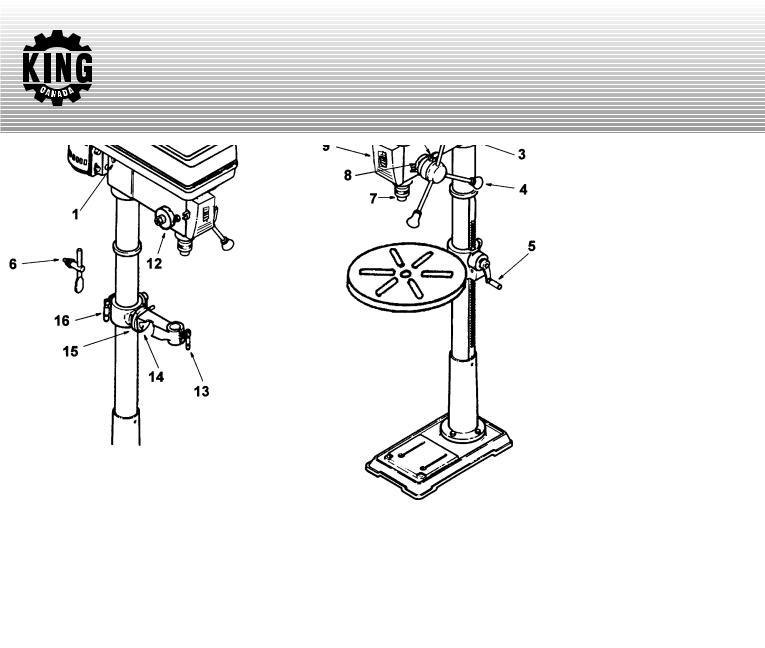
GETTING TO KNOW YOUR DRILL PRESS
FIGURE 1
LOCATION AND FUNCTION OF CONTROLS
1.Belt tension lock handles...Tightening handles locks motor bracket support to maintain correct belt distance and tension.
2.Belt tension handle...Turn handle counterclockwise to apply tension to the belt, turn clockwise to release belt tension.
3.Head locking set screws...Locks the head to the column. Always have them locked in place while operating the drill press.
4.Feed handle...For moving the chuck up or down. One or two of the handles may be removed if necessary whenever the workpiece is of such unusual shape that it interferes with the handles.
5.Table crank...Turn clockwise to elevate the table. Support lock must be released before operating crank.
6.Chuck key...Used to tighten a drill into the chuck and also to loosen the chuck for drill removal.
7.Chuck...Holds the drill bit or other recommended acessory to perform desired operations.
8.Depth scale...Allows the operator to adjust the drill press to drill to a desired depth.
9.Drill “ON-OFF” Switch...Has a locking feature to prevent unauthorized and possible hazardous use by children and others.
10.Light “ON-OFF” Switch...Turns the light on and off.
11.Depth scale lock...Locks the depth scale at the selected depth.
12.Spring cap...Provides means to adjust the quill spring tension.
13.Table lock...Allows the table to be rotated in various positions and locked.
14.Table bevel lock...Locks the table in any position from 00 to 450.
15.Bevel scale...Shows the degree in which the table is tilted for bevel operations. The scale is mounted on the side of the arm.
16.Support lock handle...Tightening locks the table support to the column. Always have it locked in place while operating the drill press.
Note and follow the safety warnings and instructions that appear on the panel on the right side of the head.
 Loading...