

Page 1
KING CANADA
16 SPEED DRILL PRESS
BENCH OR FLOOR MODEL
MODELS:
16C
KC-1
KC-1
(BENCH MODEL)
16FC
(FLOOR MODEL)
INSTRUCTION MANUAL
COPYRIGHT © 2000 ALL RIGHTS RESERVED BY KING CANADA TOOLS INC.
Page 2

IMPORTANT INFORMATION
2-YEAR
LIMITED WARRANTY
FOR THIS DRILL PRESS
PROOF OF PURCHASE
Please keep your dated proof of purchase for warranty and servicing purposes.
REPLACEMENT PARTS
Replacement parts for this tool are available at our authorized KING CANADA service centers across Canada. For servicing, contact or
return to the retailer where you purchased your product along with your proof of purchase.
LIMITED TOOL WARRANTY
KING CANADA makes every effort to ensure that this product meets high quality and durability standards. KING CANADA warrants
to the original retail consumer a 2-year limited warranty as of the date the product was purchased at retail and that each product is free
from defects in materials. Warranty does not apply to defects due directly or indirectly to misuse, abuse, negligence or accidents, repairs
or alterations and lack of maintenance. KING CANADA shall in no event be liable for death, injuries to persons or property or for
incidental, special or consequential damages arising from the use of our products. To take advantage of this warranty, the product or
part must be returned for examination by the retailer. Shipping and handling charges may apply. If a defect is found, KING CANADA
will either repair or replace the product.
OFFERS A 2-YEAR LIMITED WARRANTY
KING CANADA TOOLS
FOR NON-COMMERCIAL USE.
KING CANADA TOOLS INC.
DORVAL (MONTREAL), QUÉBEC, CANADA H9P 2Y4
Page 3

GENERAL SAFETY RULES
FOR POWER TOOLS
1. KNOW YOUR TOOL
ead and understand the owners manual and labels affixed to
R
the tool. Learn its application and limitations as well as its
pecific potential hazards.
s
2. GROUND THE TOOL.
his tool is equipped with an approved 3-conductor cord and
T
a 3-prong grounding type plug to fit the proper grounding
type receptacle. The green conductor in the cord is the
grounding wire.
terminal.
NEVER connect the green wire to a live
3. KEEP GUARDS IN PLACE.
Keep in good working order, properly adjusted and aligned.
4. REMOVE ADJUSTING KEYS AND WRENCHES.
Form habit of checking to see that keys and adjusting
wrenches are removed from tool before turning it on.
5. KEEP WORK AREA CLEAN.
Cluttered areas and benches invite accidents. Make sure the
floor is clean and not slippery due to wax and sawdust
build-up.
6. AVOID DANGEROUS ENVIRONMENT.
Don’t use power tools in damp or wet locations or expose
them to rain. Keep work area well lit and provide adequate
surrounding work space.
7. KEEP CHILDREN AWAY.
All visitors should be kept a safe distance from work area.
8. MAKE WORKSHOP CHILD-PROOF.
-with padlocks, master switches or by removing starter keys.
9. USE PROPER SPEED.
A tool will do a better and safer job when operated at the
proper speed.
10. USE RIGHT TOOL.
Don’t force the tool or the attachment to do a job for which it
was not designed.
1. WEAR PROPER APPAREL.
1
Do not wear loose clothing, gloves, neckties or jewelry (rings,
watch) because they could get caught in moving parts. Nonslip footwear is r
to contain long hair. Roll up long sleeves above the elbows.
ecommended. Wear pr
otective hair covering
12. ALWAYS WEAR SAFETY GLASSES.
lways wear safety glasses (ANSI Z87.1). Everyday
A
eyeglasses only have impact resistant lenses, they are
afety glasses. Also use a face or dust mask if cutting operation
s
s dusty.
i
13. DON’T OVERREACH.
Keep proper footing and balance at all times.
14. MAINTAIN TOOL WITH CARE.
Keep tools sharp and clean for best and safest performance.
Follow instructions for lubricating and changing accessories.
15. DISCONNECT TOOLS.
Before servicing, when changing accessories or attachments.
16. AVOID ACCIDENTAL STARTING.
Make sure the switch is in the ‘’OFF’’ position before plugging
in.
17. USE RECOMMENDED ACCESSORIES.
Consult the manual for recommended accessories. Follow the
instructions that accompany the accessories. The use of
improper accessories may cause hazards.
18. NEVER STAND ON TOOL.
Serious injury could occur if the tool tips over. Do not store
materials such that it is necessary to stand on the tool to reach
them.
19. CHECK DAMAGED PARTS.
Before further use of the tool, a guard or other parts that are
damaged should be carefully checked to ensure that they will
operate properly and perform their intended function. Check
for alignment of moving parts, breakage of parts, mounting,
and any other conditions that may affect its operation. Aguard
or other parts that are damaged should be properly repaired or
eplaced.
r
20. NEVER LEAVE MACHINE RUNNING
UNATTENDED.
Turn power ‘’OFF’’. Don’t leave any tool running until it comes
to a complete stop.
NOT
SPECIFIC SAFETY RULES
FOR DRILL PRESS
TS BEING THROWN
1. TO AVOID INJURY FROM P
BY THE SPRING
Follow the instructions exactly as given and shown in
“Adjusting the quill return spring”.
2. USING A DRILL
When using a drill press vise, always fasten it to the table.
PRESS VISE
3. NEVER DO “FREEHAND WORK”
Never do any work “Freehand” (Hand holding the workpiece
rather than supporting it on the table) except when you have
polishing to do.
AR
4. SECURE the lock head to the column, table support to
column and table to table support before operating the drill
press.
5. NEVER move the head or table while the drill press is
unning.
r
6. USE THE RECOMMENDED SPINDLE SPEED for the
specific operation and workpiece material. Check the panel
inside the guard cover for drill information. For accessories,
use the instructions provided with the accessories.
7. NEVER climb on the drill press table, you could break or pull
the entire drill press down on you.
Page 4

SPECIFICATIONS
SPECIFICATIONS FOR 13” MODELS (KC-116C, KC-116FC)
VOLTAGE ........................................................................................................................................................................................................................110V
AMPS ................................................................................................................................................................................................................................7.5A
MOTOR R.P.M. ................................................................................................................................................................................................................1700
Hz ..........................................................................................................................................................................................................................................60
PHASE ....................................................................................................................................................................................................................................1
CHUCK CAPACITY ......................................................................................................................................................................................................5/8”
SPINDLE TAPER ..........................................................................................................................................................................................................MT#2
NUMBER OF SPEEDS ........................................................................................................................................................................................................16
Page 5
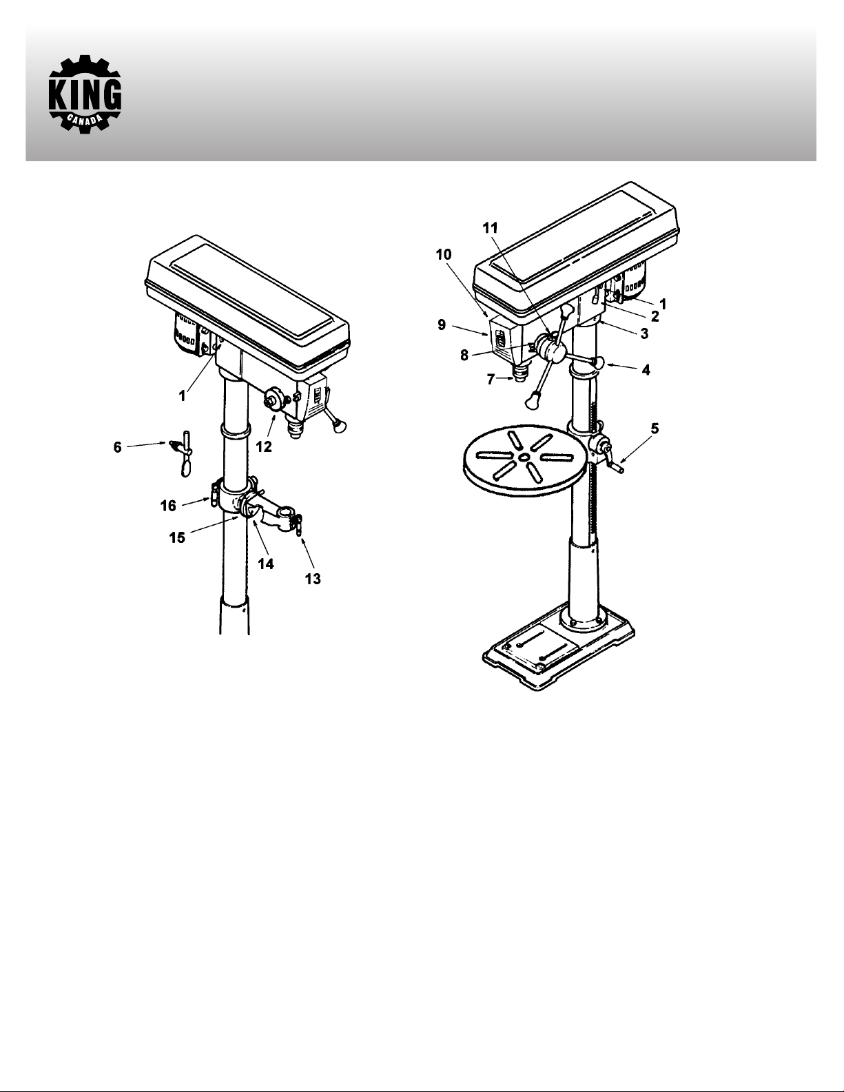
GETTING TO KNOW YOUR DRILL PRESS
FIGURE 1
LOCATION AND FUNCTION OF CONTROLS
1. Belt tension lock handles...Tightening handles locks motor
bracket support to maintain correct belt distance and tension.
2. Belt tension handle...Turn handle counterclockwise to apply
tension to the belt, turn clockwise to release belt tension.
3. Head locking set screws...Locks the head to the column. Always
have them locked in place while operating the drill press.
4. Feed handle...For moving the chuck up or down. One or two of
the handles may be r
workpiece is of such unusual shape that it interferes with the
handles.
5. Table crank...Turn clockwise to elevate the table. Support lock
must be released before operating crank.
6. Chuck key...Used to tighten a drill into the chuck and also to
loosen the chuck for drill r
7. Chuck...Holds the drill bit or other r
perform desired operations.
8. Depth scale...Allows the operator to adjust the drill press to drill
to a desired depth.
9. Drill “ON-OFF” Switch...Has a locking feature to prevent
unauthorized and possible hazardous use by children and
others.
emoved if necessary whenever the
emoval.
ecommended acessory to
10. Light “ON-OFF” Switch...Turns the light on and off.
11. Depth scale lock...Locks the depth scale at the selected depth.
12. Spring cap...Provides means to adjust the quill spring tension.
13. Table lock...Allows the table to be rotated in various positions
and locked.
14. Table bevel lock...Locks the table in any position from 00to 450.
15. Bevel scale...Shows the degr
bevel operations. The scale is mounted on the side of the arm.
16. Support lock handle...Tightening locks the table support to the
column.
press.
Note and follow the safety warnings and instructions that appear
on the panel on the right side of the head.
Always have it locked in place while operating the drill
ee in which the table is tilted for
Page 6

UNPACKING/TOOLS NEEDED
TABLE OF BOX CONTENTS
Head assembly ..............................................................................1
A-
B- Table ................................................................................................1
C- Column and table support ..........................................................1
D- Base..................................................................................................1
E- Box of loose parts ..........................................................................1
F- Bag of loose parts ..........................................................................1
G- Instruction manual........................................................................1
TABLE OF LOOSE PARTS
- Hex. hd. bolts ..................................................................................4
1
2- Set screws ........................................................................................2
3- M3 hex. key......................................................................................1
4- M5 hex. key......................................................................................1
6- Key drift............................................................................................1
7- Support lock handle ......................................................................1
8- Crank ................................................................................................1
9- Feed handles ....................................................................................3
10- Chuck key ......................................................................................1
11- Chuck ..............................................................................................1
12- Safety key ......................................................................................1
TOOLS NEEDED
- Combination square
1
1- 8” Ajustable wrench
1- Medium Phillips screwdriver
WARNING! To avoid injury from unexpected starting or
electrical shock, never connect the plug to an outlet until all the
assembly instructions are completed.
TOOLS NEEDED
FIGURE 2
Page 7

ELECTRICAL CONNECTIONS
!
!
!
!
!
ARNING
W
ALL ELECTRICAL CONNECTIONS MUST BE DONE BY A QUALIFIED ELECTRICIAN. FAILURE TO COMPLY MAY RESULT IN
SERIOUS INJURY!ALL ADJUSTMENTS OR REPAIRS MUST BE DONE WITH THE DRILL PRESS DISCONNECTED FROM THE POWER
SOURCE. FAILURE TO COMPLY MAY RESULT IN SERIOUS INJURY!
ROPERLY GROUNDED OUTLET
POWER SUPPLY
P
WARNING:
YOUR DRILL PRESS MUST BE CONNECTED TO
A 110V, 15-AMP, BRANCH CIRCUIT AND USE A 15-AMP TIME
DELAY FUSE OR CIRCUIT BREAKER. FAILURE TO CONNECT IN
THIS WAY CAN RESULT IN INJURY FROM SHOCK OR FIRE.
Your drill press must be properly grounded. Not all outlets are
properly grounded. If you are not sure if your outlet is properly
grounded, have it checked by a qualified electrician.
WARNING: IF NOT PROPERLY GROUNDED, THIS DRILL
PRESS CAN CAUSE ELECTRICAL SHOCK, PARTICULARLY
WHEN USED IN DAMP LOCATIONS. TO AVOID SHOCK OR FIRE,
IF THE POWER CORD IS WORN OR DAMAGED IN ANY WAY,
HAVE IT REPLACED IMMEDIATELY.
GROUNDING
This drill press must be grounded. If it should malfunction or
breakdown, grounding provides a path of least resistance for electric
current, to reduce the risk of electric shock. This drill press is
equipped with a cord having an equipment-grounding conductor
and grounding plug. The plug must be plugged into an appropriate
outlet that is properly installed and grounded in accordance with all
local codes and ordinances.
WARNING: TO MAINTAIN PROPER GROUNDING OF YOUR
DRILL PRESS, DO NOT REMOVE OR ALTER THE GROUNDING
PRONG IN ANY MANNER.
110V OPERATION
As received from the factory, your drill press is ready to run for 110V
operation. This drill press is intended for use on a circuit that has an
outlet and a plug which looks like the one illustrated in Fig.3.
ARNING:
W
DO NOT USE A TWO-PRONG ADAPTOR FOR
THEY ARE NOT IN ACCORDANCE WITH LOCAL CODES AND
ORDINANCES. NEVER USE IN CANADA.
EXTENSION CORDS
MOTOR
CURRENT CARRYING
PRONGS
GROUNDING
PRONG
LENGTH OF
CONDUCTOR
0-25 FEET
26-50 FEET
51-100 FEET
110V WIRING DIAGRAM
BLACK
MOTOR CORD
GREEN
WHITE
LIGHT
POWER CORD
FIGURE 3
WIRE SIZES REQUIRED
(AMERICAN WIRE GAUGE)
FIGURE 4
GREEN
WHITE
WHITE
WHITE
WIRE
CONNECT
BLACK
BLACK
GREEN
110V LINES
NO.16
NO.14
NO.12
BLACK
POWER
SWITCH
BLACK JUMPER
LIGHT
SWITCH
The use of any extension cord will cause some loss of power. Use the
following table to determine the minimum wire size (A.W.G.-American
Wire Gauge) extension cord. Use only 3-wire extension cords which
have 3-prong grounding type plugs and 3-hole receptacles which
accept the tool’s plug.
For circuits that are further away from the electrical circuit box, the wire
size must be increased pr
oportionately in or
der to deliver ample
voltage to the motor. Refer to Fig. 4 for wire length and size.
FIGURE 5
Page 8

ASSEMBLY INSTRUCTIONS
BASE AND COLUMN ASSEMBLY (FIG.6)
1. Position the base on the floor. Remove the protective covering and
discard.
2. Remove protective sleeve from the column and discard. Place the
column assembly on the base, align the holes in the column support
with the holes in the base.
. Locate four long bolts from the parts bag.
3
4. Install a bolt in each hole through the column support and the base
and tighten with the adjustable wrench.
5. Locate table crank and support lock in loose parts box.
6. Install support lock from left side into the table support and
tighten by hand. (Fig.7).
7. Install table crank assembly and tighten set screw with M3 hex. key.
Do not overtighten. The set screw should be tightened against the
flat section of the shaft. NOTE: To minimize crank backlash,
tighten support lock, rotate elevation worm shaft clockwise, then
assemble crank tight against the table support and tighten set
screw.
8. Check column collar for proper adjustment. The collar should not
be angled on the column and it should be positioned so the rack
will slide freely in the collar when the table is rotated 360
the column table. If re-adjusted, only tighten set screw enough to
keep the collar in place. NOTE: To avoid column or collar damage,
do not overtighten set screw. (Fig.8).
0
around
Column
Support lock
Table support
Column collar
Column
Rack
Column
Base
FIGURE 6
Table support
Elevation worn shaft
Handle
Table crank
FIGURE 7
Do not
overtighten
set screw
INSTALLING THE TABLE (Fig.9,10)
1. Loosen support lock and raise table support by turning the crank
clockwise until the support is at a working height level. T
support lock.
2. Remove protective covering from the table and discard. Place table
in table support and tighten table lock knob located under the table
by hand. NOTE:
open the table support with a flat head screwdriver.
If the table won’t fit in the table support easily, pry
ighten
Support lock
able support
T
Column
Table lock
FIGURE 8
Table crank
Rack
FIGURE 9
Table support
Table
FIGURE 10
Page 9

INSTALLING THE HEAD (FIG.11)
ASSEMBLY INSTRUCTIONS
1. Remove the protective covering from the head assembly.
2. Carefully lift the head above the column and slide it down on the
column as far as it will go. Align the head with the table and the
base.
3. Using a hex. wrench, tighten the head set screws on the right side
of the head.
PULLEY ALIGNMENT AND SPEED ADJUSTMENT
Checking pulley alignment
Warning:
always turn drill press off and remove safety key before making belt
adjustments.
The pulleys and motor are assembled at the factory and should
require no further adjustment. If the pulleys or motor are removed for
service, follow the pulley alignment instructions below.
1. Place a straightedge such as a piece of wood, metal, or framing
square across the top of the pulleys.
2. The top of all three pulleys should touch the straightedge.
3. If not, a) Loosen motor mount nuts. b)Move motor until the pulleys
are in line. c) Retighten the motor mount nuts.
NOTE: To avoid rattles or other noises, motor frame must not touch
lower belt guard.
Speed adjustment
To reduce the risk of injury due to accidental starting
Lower belt
guard
FIGURE 11
Belt tension
lock handle
FIGURE 12
Head
Head
Motor mount
nuts
Head locking
et screws
s
Motor
1. Release belt tension lock handles located on each side of the drill
press by turning them counterclockwise.
2. Loosen belt tension by turning the belt tension handle clockwise.
3. Use the speed chart inside the belt guard to choose the speed for the
drilling operation. Install belts in the correct position for the
desired speed. The longer of the two belts is always positioned
between the spindle pulley and the idler pulley.
NOTE: Refer to inside belt guard for r
TENSIONING BEL
1. Apply tension to the belt by turning belt tension handle counterclockwise until belt deflects appr
pressure at its center.
2. Tighten belt tension lock handles.
cause the motor not to start or damage bearings.
3. If belt slips while drilling, r
T
eajust belt tension.
ecommended drilling speeds.
oximately 1/2” by thumb
NOTE: Over tensioning belt may
Belt tension
handle
Spindle pulley
Idler pulley
FIGURE 13
Belt tension
lock handle
Belt tension handle
FIGURE 14
Page 10

ASSEMBLY INSTRUCTIONS
INSTALLING THE CHUCK
. Clean out the tapered hole in the chuck, clean the spindle nose with
1
a clean cloth. Make sure there are no foreign particles sticking to the
urfaces. The slightest piece of dirt on the spindle nose or on the
s
chuck will prevent the chuck from seating properly. This will cause
the drill to “wobble”.
2. Slide the chuck up over the arbor as illustrated in Fig.15.
3. Unlock the table support lock and raise the table so that it is two
inches below the tip of the chuck.
4. Turn the chuck sleeve clockwise and open jaws in chuck completely.
5. Turn the feed handles counterclockwise and force the chuck against
the table until the chuck is secure.(Fig.16).
Quill
Arbor
huck
C
FIGURE 15
Feed
handle
REMOVING CHUCK AND ARBOR
1. With the switch off, adjust the depth scale to hold the drill at a depth
of 3” (see instructions for “Locking chuck at desired height”).
2. Align key holes in spindle and quill by rotating the chuck by hand.
3. Insert key drift into key holes.
4. Tap key drift lightly until the chuck and arbor fall out of the spindle.
NOTE: Place one hand below the chuck to catch it when it falls out.
(Fig.17).
INSTALLING LIGHT BULB
1. Install a light bulb (no larger that 60Watts) into the socket inside the
head. (Fig.18).
FIGURE 16
Key
drift
Chuck
sleeve
Chuck
body
FIGURE 17
FIGURE 18
Page 11

ADJUSTMENTS
ADJUSTING THE TABLE SQUARE TO THE HEAD
: The combination square must be “true”.
NOTE
1. Insert precision round steel rod or straight drill bit approximately 3”
ong into the chuck and tighten.
l
2. With the table raised to work height and locked to the column, place the
ombination square flat on the table beside the rod or drill bit.(Fig.19).
c
3. If an adjustment is necessary, loosen the set screw under the bevel lock
with 3mm hex. key, then loosen the table bevel lock bolt with the open
wrench included. This adjustment is located under the work table.
4. Align the table square to the rod or drill bit by pivoting the table they
are in line.
5. Retighten table bevel lock.
6. Retighten set screw.
BEVEL SCALE
: The bevel scale has been included to provide a quick method for
NOTE
beveling the table to approximate angles. If precise accuracy is necessary,
a square, or other precision measuring tool should be used to position the
table.
Set screw
Table
Table
bevel lock
FIGURE 19
Table
1. To use the bevel scale do the following: a) Loosen set screw and table
bevel lock (See step 3 above for reference). b) Move table so that desired
angle on the bevel scale is straight across from the zero line on the table.
c) Retighten table bevel lock and set screw.
DRILLING TO A SPECIFIC DEPTH
To drill a blind hole (not all the way through) to a given depth, proceed as
follows.
1. Mark the depth of the hole on the workpiece.
2. Loosen the depth scale lock.
3. With the switch OFF, bring the drill bit down until the tip of the lips of
the drill bit are even with the mark.
urn the depth scale counter
4. T
5. Tighten the depth scale lock.
6. The drill bit will stop at this depth until the depth scale is readjusted.
ANOTHER WAY-DEPTH SCALE
1. With the power OFF, loosen the depth scale lock.
2. Place workpiece on table. Adjust table until the tip of the drill is just a
little above the top of the workpiece, turn the depth scale counterclockwise to zero.
3. Turn the depth scale clockwise until the depth scale indicator points to
the desired drilling depth on the depth scale.
4. Tighten the depth scale lock.
5. The chuck or drill will now be stopped after traveling downward the
distance selected on the depth scale.
clockwise until it stops moving.
Pointer
Depth sacle
indicator
Depth scale
Mark
Scale
FIGURE 20
Depth scale lock
FIGURE 21
Page 12

AJUSTEMENTS & OPÉRATIONS
OCKING CHUCK AT DESIRED DEPTH
L
1. With the switch off, loosen the depth scale lock.
2. Turn the feed handles until the chuck is at the desired height. Hold the
feed handles at this position.
3. Turn the depth scale clockwise until it stops.
4. Tighten the depth scale lock.
. The chuck will now be held at the depth when the feed handles are
5
released.
BASIC DRILL PRESS OPERATIONS
INSTALLING DRILL BITS
Insert drill bit into chuck far enough to obtain maximum gripping of the
chuck jaws (fig.23). The jaws are approximately 1” long. When using a
small drill bit, do not insert it so far that the jaws touch the flutes (spiral
grooves) of the drill bit. Make sure the drill bit is centered in the chuck
before tightening the chuck with the key.
Tighten the drill bit sufficiently, so that it does not slip while drilling. Turn
the chuck key clockwise to tighten, counterclockwise to loosen.
POSITIONNING THE TABLE AND WORKPIECE
Lock the table to the column in a position so that the tip of the drill bit is
just a little above the top of the workpiece.
Always place backup material (wood, plywood...) on the table underneath
the workpiece. This will prevent “splintering” or making a heavy burr on
the underside of the workpiece as the drill bit breaks through. To keep the
backup material from spinning out of control, it must contact the left side
of the column, as illustrated in fig.24.
Depth scale lock
Depth scale
Adjust to
desired depth
FIGURE 22
Chuck key
Chuck
WARNING! If the backup material is not long enough to reach the left
side of the column, clamp it to the table. Failure to do this could result in
personnal injury.
For small workpieces that can’t be clamp to the table, use a drill press vise
(optional accessory) (Fig.25). See authorized KING CANADA retailer for
more information on purchasing drill press vises.
WARNING! The vise must be clamped or bolted to the table to reduce the
risk of injury from spinning work or vise or tool breakage.
orkpiece
W
Drill press
vise
Jaws
FIGURE 23
Workpiece
Backup
material
Bolt or clamp vise securely
FIGURE 25
FIGURE 24
Page 13

TILTING TABLE
ADJUSTMENTS & OPERATIONS
To use the table in a bevel (tilted) position (Fig.26), loosen the set
screw under the table bevel lock with a 3mm hex. key. Loosen bevel
lock using open end wrench included. Tilt the table to the desired
angle by reading the bevel scale. Retighten bevel lock and set screw.
WARNING: To reduce the risk of injury from spinning work or
tool breakage, always clamp workpiece and backup material
securely to the table before operating the drill press with the table
tilted.
To return the table to its original position, loosen the set screw and
bevel lock, tilt the table back to zero on the bevel scale and
retighten set screw, then retighten the bevel lock.
HOLE LOCATION
Make a dent in the workpiece where you want the hole to be, using
a center punch or a nail. Before turning the switch on, bring the
drill down to the workpiece and line up with the dent in the
workpiece and clamp into place.
FEEDING
Pull down on the feed handles with only enough effort to allow the
drill to cut. Feeding too slowly might cause the drill to burn.
Feeding too rapidly might stop the motor, cause the belt or drill to
slip, tear the workpiece loose or break the drill bit. When drilling
metal, it may be necessary to lubricate the tip of the drill bit with
cutting oil or motor oil to prevent burning of the drill tip.
10. Proper tension is achieved when the quill returns gently to the
full up position when released from 3/4” depth.
11. When there is enough tension after checking, replace outer nut
and tighten inner nut. Do not over tighten against the inner nut.
12. Check quill while feeding to have smooth and unrestricted
movement. If movement is too tight, loosen outer nut and
slightly loosen inner nut until unrestricted. Retighten outer nut.
Bevel lock
Bevel scale
Set screw
FIGURE 26
ADJUSTING THE QUILL RETURN SPRING
: The return spring tension is set at the factory and should
NOTE
not require further adjustment.
ith the chuck at its highest possible position, turn the depth
1. W
scale clockwise until it stops and tighten the depth scale lock.
This will prevent the quill from dropping while tensioning the
spring.
2. Lower the table for additional clearance.
3. Work from the left side of the drill press.
4. Place scr
hold it in place while loosening and removing the outer nut
(only).
5. W
(approx. 1/8”) until the notch disengages from the boss on the
head. Do not remove this nut.
6. Carefully turn screwdriver counterclockwise and engage the
next notch in the boss. Do not r
7. Tighten standard nut with wr
Do not over tighten as this will restrict quill movement.
8. Move stop nuts and depth pointer to upper most position and
check tension while turning feed handles.
9. If there is not enough tension on the spring, repeat steps 4-8
moving only one notch each time and checking tension after
each repetition.
ewdriver in the lower fr
ith screwdriver remaining in the notch, loosen inner nut
ont notch of the spring cap, and
emove scr
ench only enough to engage boss.
ewdriver
.
Notch
(outer)
Nut
Nut
(inner)
Boss
Spring
cap
Notch
FIGURE 27
Page 14

MAINTENANCE / TROUBLESHOOTING
UBRICATION
L
All of the ball bearings are packed with grease at the factory. They require no further lubrication. Periodically lubricate the splines
(Grooves) in the spindle and the rack (Teeth of the quill).
WARNING! For your own safety, turn the switch “OFF” and remove the plug from the power source before maintaining or lubricating
your drill press.
Frequently blow out any dust that may accumulate inside the motor. After operation, remove chips or dirt on the machine and apply a
coat of furniture-type paste wax to the table and the column, this will help keep the surfaces clean and free of rust.
PROBLEM
Noisy operation.
Drill bit burns.
Wood splinters on
underside of workpiece.
Workpiece torn loose
om hand.
fr
Drill bit binds in workpiece.
Excessive drill bit
wobbling.
PROBABLE CAUSE
1. Incorrect belt tension.
2. Dry spindle.
3. Loose spindle pulley.
4. Loose motor pulley.
1. Incorrect speed.
2. Chips not coming out of hole.
3. Dull drill bit.
4. Feeding too slow.
5. Not lubricated.
1. No “Back-up material” under the workpiece.
1. Not supported or clamped properly.
1. Workpiece is pinching the drill bit or
there is an excessive feeding pressure.
2. Improper belt tension.
1. Bent drill bit.
2. Worn spindle bearings.
3. Drill bit is not pr
chuck.
4. Chuck not properly installed.
operly installed in the
SOLUTION
1. Adjust the tension.
2. Lubricate the spindle.
3. Tighten the retaining nut on the pulley as needed.
4. Tighten the set screws which hold the pulleys in place.
1. Change the speed.
2. Retract the drill bit frequently to clear the chips.
3. Resharpen the drill bit.
4. Feeding too fast...allow the drill bit to cut.
5. Lubricate the drill bit with cutting or motor oil.
1. Support the workpiece or clamp it.
1. Support the workpiece or clamp it.
1. Support the workpiece or clamp it.
2. Adjust the tension of the belt.
1. Use a straight drill bit.
2. Replace the bearings.
3. Install drill bit pr
4. Install chuck properly.
operly.
Quill r
eturns too fast or
too slow
Chuck will not stay
attached to the spindle.
It falls off when trying
to install it.
PARTS DIAGRAM & P
Refer to the Parts section of the King Canada web site for the most updated parts diagram and parts list.
.
1. Spring has impr
1. Dirt, grease or oil on the tapered inside
surface of the chuck or on the spindle
tapered surface.
TS LISTS
AR
oper tension.
1.
Adjust the spring tension.
1. Using a household detergent, clean the tapered surfaces of the chuck and the spindle to remove the dirt,
grease and oil.
Page 15

INSTRUCTIONS FOR DUAL LASER GUIDE SYSTEM
USING/ADJUSTING DUAL LASER GUIDE SYSTEM
WARNING! Do not look directly at the laser beams. Do not aim the laser beams at any person or any object other than
your workpiece. Do not deliberately aim the beams into the eye of a person for any length of time.
guide system aimed at a reflective workpiece, wood or rough coated surfaces are acceptable. This is to avoid the laser beams
from being reflected back at the operator.
Using the dual laser guides system;
Your laser guides are battery operated (2 x AA batteries) and
must be installed inside the laser switch/battery cover (A)
Fig.1. To remove this cover pressure must be applied to the
top and bottom, then you simply pull gently on the cover. Do
not yank the switch off, internal wires are attached to it. When
positioning the batteries, make sure they are positioned with
the correct polarity. Replace the laser/battery cover. Turn the
laser switch on to make sure the dual laser guide system
works.
1) Mark the drilling point on your workpiece.
2) Plug in the drill press and turn the motor on.
3) Switch on the laser guides and align the drilling point with the intersecting point of the laser guides.
4) Secure workpiece to the table with a vise or clamps.
5) Slowly feed the drill bit into the workpiece.
6) Switch off the dual laser guide system on completion of the drilling operation.
Fig.1
Do not use the laser
Fig.2
Adjusting the dual laser guide system;
If adjustments to the laser guides are necessary, proceed as follows;
1) Loosen set screw (A) Fig.2 (one set screw for each laser) and then slightly turn laser guide (B) Fig.2 in either direction, this
will reposition the laser beams trajectory, adjust the position of the laser guides this way until both beams intersect at the point
where the drill bit touches the workpiece. Retighten set screw (A) after each adjustment.
Caution: Remove the laser guide batteries from the battery compartment if you plan on storing your drill press for more than a
few days. If left in position, the batteries could leak and damage the laser guide assembly. Damage due to leaking batteries is
not covered under warranty.
 Loading...