

Kindermann Klick & Show K-10S, Klick & Show K-10L Lite Installation And User Manual
Wireless Presentation Solution
Klick & Show K-10S - Art.-Nr. 7488000300
Klick & Show K-10L Lite - Art.-Nr. 7488000305
Installation and User Manual
Release: Firmware 3.0.6 C / E
5.2019

Overview
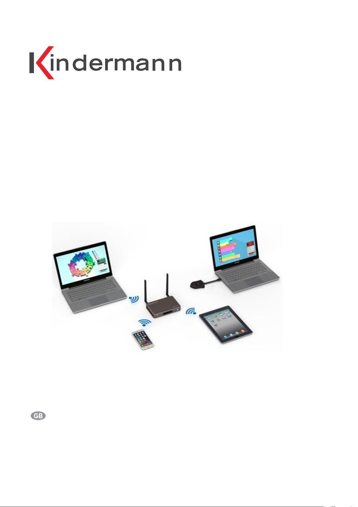
The Kindermann Klick & Show K-10S is a modern Wireless Presentation System for small to mid-sized meeting
rooms, classrooms and huddle spaces. Klick & Show allows users to share content from their laptops or mobile
devices in a simple way – with no configuration, no cables and without wasting time. Windows/Mac users simply
connect the Klick & Show TOUCH Transmitter to a USB port of their laptop. With a touch on the sensor button
the live laptop content is mirrored to the main display device. The universal starter program "WirelessMedia for
Windows" can also be used without TOUCH sensor button (with LAN or Wi-Fi from the laptop). Users of
Apple/Android smart devices can download our free apps to share their content or use Airplay (iOS only). In
addition, Klick & Show K-10S offers a 4K HDMI input to display wired content from PC / DVD.
The Klick & Show K-10S Kit (7488000300) already contains of one Base-unit and two Senor-buttons TOUCH
(7488000301). Additional Sensor-buttons TOUCH (7488000301) are available.
The Kindermann Klick & Show K-10L Lite is only supplied with the Base-unit, with accessories, but without the
TOUCH transmitter. Windows / Mac users simply start the Klick & Show Universal PC-Client Software on the
laptop (available from www.klickandshow.com or from the base unit for download) to mirror content to the main
screen. If required, up to four additional sensor buttons (7488000301) are available and connectable at the same
time.
The current version of this manual can also be downloaded from the website www.klickandshow.com.
Go to the DOWNLOAD/Documentation tab.
Contents Klick & Show K-10S Kit (7488000300)
1 Kindermann Klick & Show Base-unit
2 Antenna
2 Klick & Show Sensor-buttons TOUCH
2 USB-token with Windows-, MAC-driver, User manual (PDF)
2 Closing flaps with screws, for USB-token in Sensor-button TOUCH
1 Universal power-supply 100 – 240 VAC, 12 VDC/2A, with different adapters
1 Mounting set for installation at wall
1 Quick-start-Guide
Contents Klick & Show K-10L Lite (7488000305)
1 Kindermann Klick & Show Base-unit
2 Antenna
1 Universal power-supply 100 – 240 VAC, 12 VDC/2A, with different adapters
1 Mounting set for installation at wall
1 Quick-start-Guide
Table of contents
2

Main features
Wireless transmission of Windows or Mac laptops / PCs to a central screen
Can transmit PC’s mirror/extended windows-desktop (depending on the operating system,
Klick & show "Extension Display" driver may be required) or mirror of Macbook desktop to the Base-unit
(extended desktop is possible via AirPlay)
Preview function of connected laptops (max. 14)
Can transmit smart devices' mirror, photos, videos, music etc., supports AirPlay 2
Transmits USB-HID (f.e. mouse) for interactive units (Touch-displays, interactive WhiteBoard)
Support VESA PC resolution input, auto-detecting
Can remote monitoring the active display on screen from a smart devices (“Remote View”)
Support remote mouse to control the active source devices from other smart devices (“Remote Control”)
External HDMI-Input at Base-unit for cable-linked connection to another video-source
(PC, document camera, DVD, …)
Universal Starter-program "WirelessMedia" for Windows or Mac laptop / PC for use with or without
Sensor-button TOUCH (using LAN or Wi-Fi of laptop) – see chapter 6.1.
New graphic design (GUI) of Starter-program "WirelessMedia" for Windows with or without touch
sensor TOUCH usable (with LAN or Wi-Fi from laptop) - see chap. 6.1.
Optional Starter-Program "WirelessMedia-pro" for Windows, for use with or without
Sensor-button; if it is not possible to install the standard driver "WirelessMedia" for Windows,
due to IT administrator security policies - see chap. 6.1.
Support Over-the-Air (OTA) for automatic (option) firmware upgrading via Ethernet – see chap. 5.7.
Sensor-buttons TOUCH
Sensor-button with "Show-me" function with fast signal switching (app. 1s)
Status display with colored LEDs: green indicates active source signal, red indicates power/link.
Support USB plug-in auto configuration/pairing at Base-unit
“Show-me" button can independently step in/out the source of PC
New features Firmware 3.0
Dual Network, provides the access to Base-unit from either Guest Wi-Fi network or secure
Corporation network without the need to change the Wi-Fi for not only Guest but also the
company staff, see chap. 5.2.
White Board & Annotation, to be compliant with the touch screen, which supports USB HID
touch technology for quickly start free writing, or annotations to a picture / text for capturing
ideas, thoughts and inspiration better, see chap. 4.4.
Security Settings can be set in three levels, as required by the organization, see chap. 5.5.
Table of contents
3
Accessory:
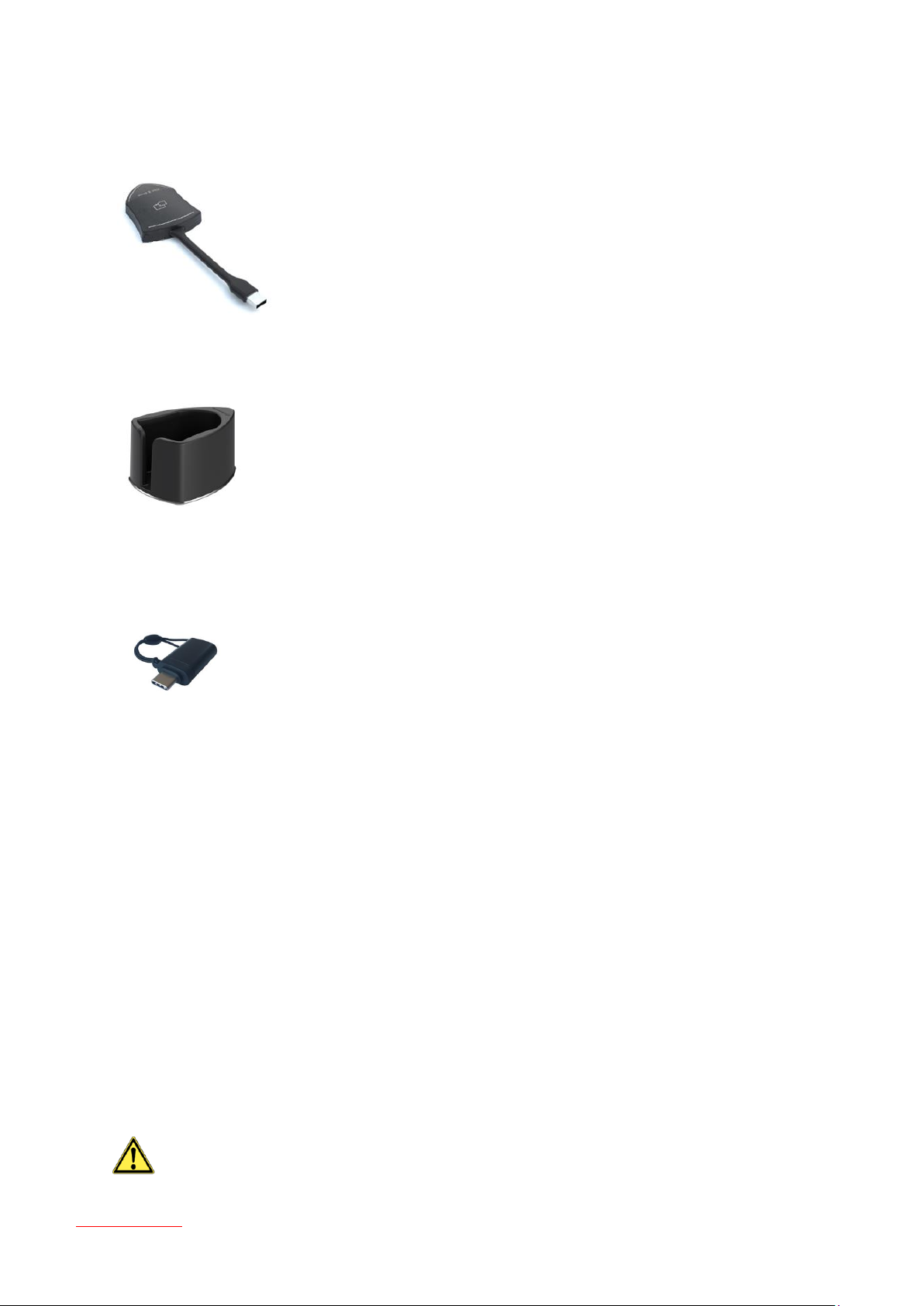
Klick+Show TOUCH T1 Transmitter (7488000301)
Sensor-button for expansion of Klick & Show K-10S Kit
Klick+Show TRAY (7488000303)
Tray for four Sensor-Buttons TOUCH
Klick+Show USB-C Cap (7488000304)
USB Typ-C adapter for use with Klick & Show TOUCH Transmitters at USB-C port at PCs/Mac.
Safety instructions
WARNING
Table of contents
4

Please read the instructions carefully and store them
The Kindermann Klick & Show K-10S can only be operated with a safety low voltage via the
associated power supply unit
The device must only be stored and used in a dry, closed environment without mechanical stress
Install the unit in a place with adequate ventilation
Do not use any liquids or thinners for cleaning (remove the power supply before use!)
Remove the power supply for long periods of non-use!
The use of unsuitable accessories may result in damage or malfunction
Please observe the safety instructions of the devices to be connected
Table of contents
5

Contents
1. Overview ............................................................................................................................. 10
1.1 Action Chart ................................................................................................................................................. 10
1.2 Network-Integration: ................................................................................................................................. 11
1.2.1 Standard (Direct-mode, Guest or Staff) .................................................................................................... 11
1.2.2 Standard with existing Access Point (Direct-mode) ................................................................................ 11
2. Device Setup ....................................................................................................................... 12
2.1 Connections and Buttons ........................................................................................................................ 12
2.1.1 Front Panel ....................................................................................................................................................... 12
2.1.2 Rear Panel ......................................................................................................................................................... 13
2.1.3 Factory Reset .................................................................................................................................................... 14
2.2 Sensor-Button TOUCH ............................................................................................................................... 16
2.3 User Interface .............................................................................................................................................. 17
2.3.1 Home screen .................................................................................................................................................... 17
3. Installation .......................................................................................................................... 20
3.1 Installation methods for the Base-unit .................................................................................................... 20
3.2 Wiring Diagramm Base-unit ..................................................................................................................... 21
3.3 Power Connection ....................................................................................................................................... 21
3.4 Video Connection ........................................................................................................................................ 22
3.5 Audio Connection ....................................................................................................................................... 23
3.6 LAN Connection .......................................................................................................................................... 24
3.7 Usage of USB device ................................................................................................................................... 25
4. Getting started with Klick & Show .................................................................................. 26
4.1 Mobile units: Wireless Connection ........................................................................................................... 26
4.1.1 Enable portable access point: ........................................................................................................................ 27
4.2 Pairing Sensor-button with Base-unit ..................................................................................................... 27
4.3 Mirroring of the desktop - First steps ............................................................................................... 29
4.3.1 PC / Laptop ....................................................................................................................................................... 29
6
Table of contents

4.3.2 Mobile Devices ................................................................................................................................................. 30
4.4. Whiteboard & Annotation......................................................................................................................... 32
4.4.1 Whiteboard ....................................................................................................................................................... 33
4.4.2 Annotation ........................................................................................................................................................ 34
5. Settings in Main-menu ..................................................................................................... 36
5.1 Ethernet ........................................................................................................................................................ 37
5.1.1 IP address ......................................................................................................................................................... 37
5.1.2 Ethernet MAC address .................................................................................................................................... 37
5.1.3 Proxy & IP settings .......................................................................................................................................... 37
5.1.4 PPPoE settings.................................................................................................................................................. 38
5.2 Wireless & network .................................................................................................................................... 38
5.2.1 Wireless network configuration wizard ........................................................................................................ 40
5.2.1.1 Wireless Direct Mode ............................................................................................................................................... 40
5.2.1.2 Wireless Infrastructure mode .................................................................................................................................. 44
5.2.1.3 LAN Infrastructure Mode ......................................................................................................................................... 46
5.2.1.4 Firewall Settings ........................................................................................................................................................ 47
5.2.1.5 Network Configuration Diagram ............................................................................................................................ 50
5.2.2 Show Wi-Fi name and Wi-Fi password in main screen ............................................................................. 50
5.2.3 Auto change Wi-Fi access point password................................................................................................... 51
5.2.4 Wi-Fi analyzer ................................................................................................................................................... 52
5.3 Moderator Control ...................................................................................................................................... 54
5.3.3 Preview window ............................................................................................................................................... 54
5.4 General settings .......................................................................................................................................... 55
5.4.3 Automatic creation of Starter-program ........................................................................................................ 55
5.4.4 Auto Standby ................................................................................................................................................... 55
5.4.5 AirPlay screen quality ...................................................................................................................................... 56
5.4.6 HDMI output resolution.................................................................................................................................. 56
5.4.7 HDMI input AUTO switch ............................................................................................................................... 56
5.4.8 Background image Home screen .................................................................................................................. 57
5.4.9 Volume .............................................................................................................................................................. 57
5.5 Security setting ........................................................................................................................................... 57
Table of contents
7

5.5.1 Security level .................................................................................................................................................... 57
5.5.2 LAN discovery & Connection ......................................................................................................................... 58
5.5.3 “Remote View” lock ......................................................................................................................................... 59
5.5.4 Show PC’s user status when mirroring (Yes/No) : ....................................................................................... 59
5.5.5 Clear History after meeting ............................................................................................................................ 59
5.5.6 Change admin password ................................................................................................................................ 60
5.6 Language & input ....................................................................................................................................... 60
5.7 System Update ............................................................................................................................................ 60
5.8 Date & Time ................................................................................................................................................. 61
5.9 About Device ............................................................................................................................................... 62
6. Operate Klick & Show ....................................................................................................... 63
6.1 Mirroring PC desktop ................................................................................................................................. 63
6.1.1 Extended Desktop for Windows 10 ............................................................................................................... 63
6.1.2 Microsoft Windows PC / Laptop, with Sensor-button TOUCH .................................................................. 63
6.1.3 Microsoft Windows PC / Laptop, without Sensor-button TOUCH ............................................................ 65
6.1.4 Options für Microsoft Windows PC / Laptop – Extended Screen .............................................................. 67
6.1.5 Mac OS PC/Laptop, with Sensor-button TOUCH ........................................................................................ 70
6.1.6 Mac OS PC/Laptop, without Sensor-button TOUCH .................................................................................. 72
6.1.7 Optionen für Apple MacOS, MacBook – Extended screen ......................................................................... 74
6.2 Transmitting iOS mobile device ............................................................................................................... 76
6.2.1 How to use AirPlay?......................................................................................................................................... 76
6.2.2 App “WirelessMedia” for iOS ......................................................................................................................... 76
6.3 Transmitting Android device wireless ..................................................................................................... 81
6.3.1 “WirelessMedia” Apk for Android .................................................................................................................. 81
6.4 HDMI Input Select ...................................................................................................................................... 84
7. Firmware-Update ............................................................................................................... 86
7.1 Check current firmware information ....................................................................................................... 86
7.2 Upgrading Firmware Base-unit ................................................................................................................. 87
7.3 Upgrading and Pairing of Sensor-button TOUCH ................................................................................. 88
7.4 Software update of USB-token ................................................................................................................. 89
7.5 Install newer version of Starter-Program at Laptop ............................................................................. 89
Table of contents
8

7.6 Clean left files of older versions of Starter-program in Laptop .......................................................... 91
8. TCP/IP Commands: Telnet ................................................................................................ 92
9. Specifications Klick & Show ............................................................................................. 93
9.1 Dimensions ................................................................................................................................................... 95
9.2 Open Source-Software provisions ............................................................................................................ 96
9.3 EG-declaration ................................................................................................................................................ 98
10. Trouble Shooting ............................................................................................................... 99
Table of contents
9
1. Overview
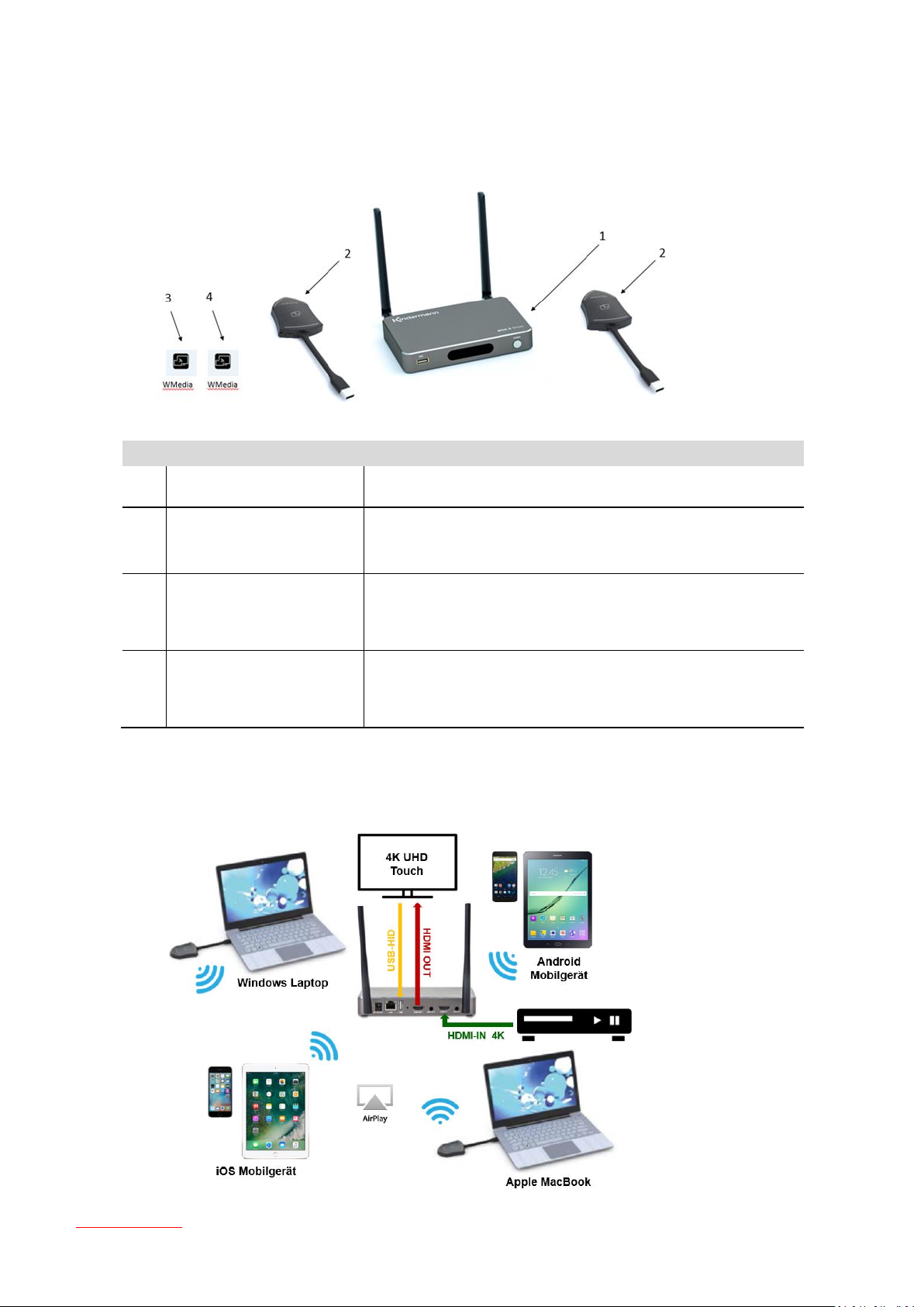
ID
Name
Description
1
Klick & Show Base-unit
Host / Base-unit with Wi-Fi receiver
2
Sensor-button TOUCH
Sensor-button with Wi-Fi transmitter for PC/Laptop to share the
desktop/extended desktop
3
WirelessMedia for Android
App for smart android devices to share the screen, transmit
photos/music/video/files, exchange files, “Remote View” and
“Remote mouse”.
4
WirelessMedia for iOS
App for smart iOS devices to share the screen, transmit
photos/music/video/files, exchange files, “Remote View” and
“Remote mouse”.
1.1 Action Chart
Table of contents
10

1.2 Network-Integration:
1.2.1 Standard (Direct-mode, Guest or Staff)
1.2.2 Standard with existing Access Point (Direct-mode)
• Function depends on the infrastructure of the network in the company.
Access to the GUEST-AP may be blocked by firewall settings in the company network.
11
Table of contents
2. Device Setup
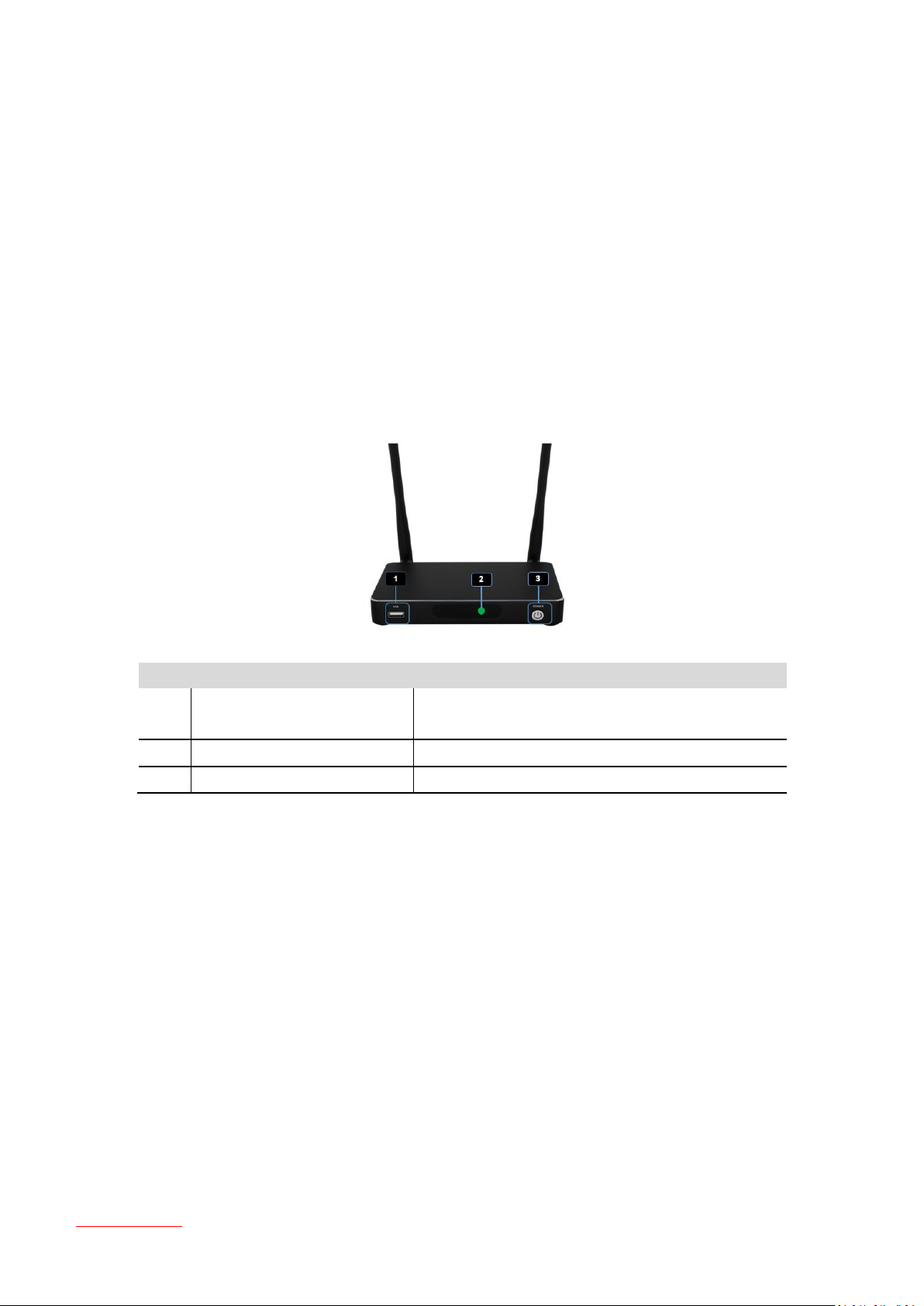
ID
Name
Description
1
Front USB connector
USB port, for Klick & Show TOUCH pairing, mouse
control, USB touch screen, firmware upgrading
2
STANDBY-LED
STANDBY-mode: green LED (2) flashing
3
POWER button with LED indicator
Unit ON/OFF with green status-LED ON/OFF
2.1 Connections and Buttons
Overview
Front panel
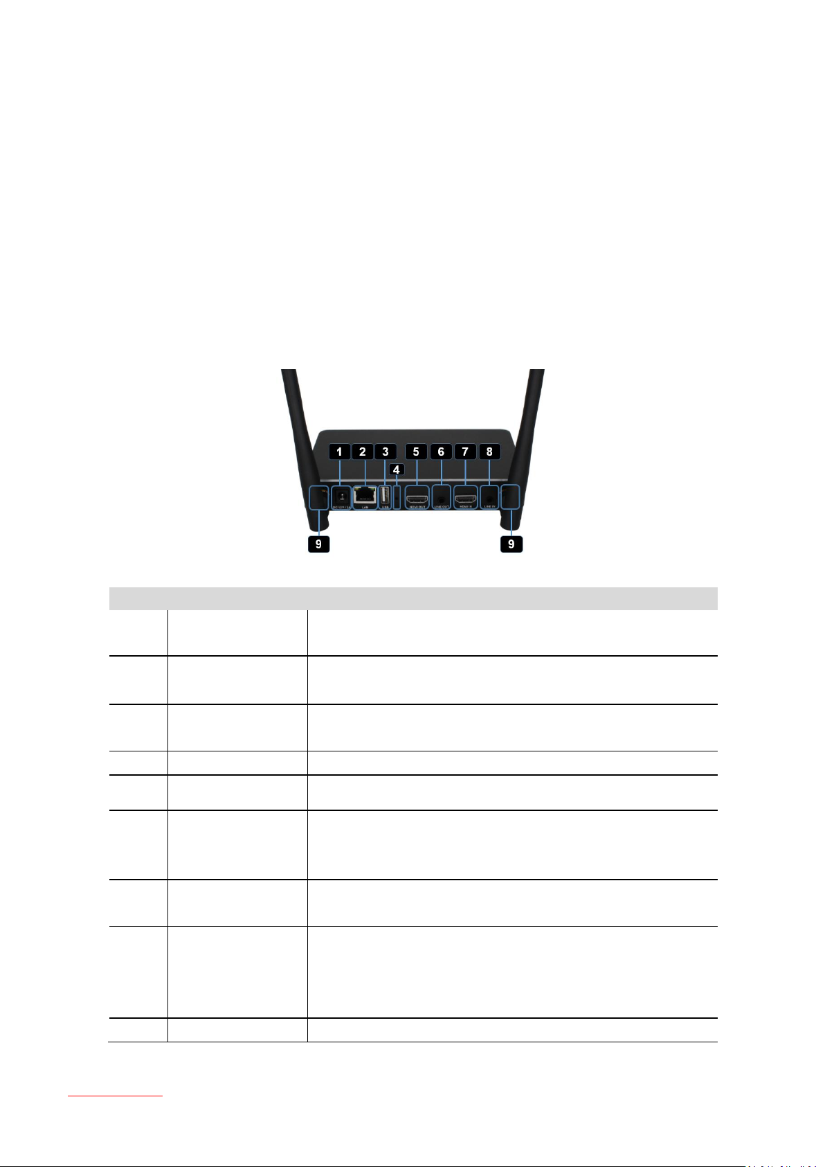
Rear Panel
Sensor-button TOUCH
2.1.1 Front Panel
USB port
To be able to use a Sensor-button it should be paired to the Base-unit you are using. Insert the sensor
button to an USB port of the Base-unit you are using. If necessary, the Firmware of the button is automatically
updating. Follow the instructions at screen.
Other functions of USB-port.
The USB port is used to update the software of Klick & Show.
The USB port is used for connecting a mouse to:
- Navigate in the SETTING configuration
- Control a PC desktop that is mirroring to the screen by using the Sensor-button TOUCH
Instead of a Mouse also a local connected touch Screen can be used
Table of contents
12
Via this USB Port you can create a USB Stick containing the Starter-Program-Software for the Sensor-
ID
Name
Description
1
DC Power socket
Connect the included power adapter DC 12V/2A to this socket, and
connect the plug to an available electrical outlet
2
LAN
Connect an Ethernet cable between this jack and a LAN to connect the
Base-unit to LAN; PoE ready
3
USB port
USB port, for pairing Sensor-button TOUCH, mouse control, USB touch
screen etc.; same functions as front-USB
4
Reset
for restoring the factory default setting (needs tool)
5
HDMI OUT
To connect an HD or 4K/HDMI 2.0 output device
6
LINE OUT
2 channel analog audio output, de-embedded from HDMI OUT;
connect a 3.5 mm mini-jack PC connector from this jack to the LINE IN
jack of an audio system
7
HDMI IN
Connect a local HDMI output (PC, document camera, DVD) up to
4K/60Hz, HDCP 2.2 source device
8
LINE IN
2-channel analog audio input is only active, when it detects no audio
signal in HDMI IN data flow, like DVI-Input. Connect a 3.5 mm mini-jack
PC connector from this jack to the Line Out jack of external audio
source devices
9
ANT.
Screw up the included two antennas to these two ports
button TOUCH
POWER button
The button at the front of the Base-unit has a power on/off function once the Base-unit is powered.
Pressing the Button switches the unit on and off in Deep-Standby: the Base-unit shuts down completely, Wi-Fi is
deactivated, and can only be turned on by the POWER button. Green LED in button signals status.
2.1.2 Rear Panel
Table of contents
13

2.1.3 Factory Reset
On pressing the Reset button, a Hardware-reset is initiated at Base-unit. A „FACTORY RESET“, can also be
performed via the menu „System Update“ / „Factory Reset”, see chapter 5.7. Both types will be set the unit
back to default.
All data of configuration will be lost. So that you do not have to re-configure all data in an elaborate
process, note all settings within the Sub-menus before doing Factory Reset.
Start up the Base-unit.
When the Home screen is shown up, press the reset button at the rear panel of Base-unit. Press this button
with a pointed object, e.g. an unbent paper clip, until the “Factory Reset” page is shown up as below, for at
least 2 seconds.
The Base-unit will reboot after 3 seconds to be default configuration.
If you do not have a picture, press and hold the reset button until the blue LED in the front window will lit,
to execute the reset.
All previous settings will be lost and you will need to do the set-up once more.
After Reset, all Sensor-buttons TOUCH must be paired again to Base-unit, because SSID has changed
(see chapter 4.2).
Table of contents
14

Factory settings after Reset
Ethernet
o Proxy: None
o IP setting: DHCP
Tethering & portable access point
o Wi-Fi-Network mode: Wi-Fi Direct mode, connected DUAL network
SSID: KlickandShow-xxxx,
Password: 0000xxxx
Guest-SSID: SSID Klick & Show-xxxx
STAFF-SSID: Staff SSID
Security: WPA2 PSK
Frequency: 5 GHZ
Channel: 40
o Auto change of Wi-Fi password: every 5 minutes, when there is no signal
Moderator Control
o Preview windows: ON
Settings
o Auto create launcher (Starter APP): OFF
o Auto Standby: Never
o AirPlay quality: High
o Resolution HDMI OUT: 1920x1080p@60Hz
o HDMI-input AUTO switch: Manual
o Background image Home screen: Standard
o Volume: 100
Security setting
o Security level: Level 1
o LAN connection: Enable mobile devices can discover/connect the Base-unit in same LAN: OFF
o Disable “Remote View” from mobile device application: ON
o Show PC’s user name when mirroring: ON
o Clear history after meeting: Always
o Password for menu: admin (Please change password on first login!)
Language: English
System Update Upgrading Mode Setting of firmware: manual
Date & time Automatic date & time: use network-provided time: ON
Use 24-hour format: ON
Time zone: GMT +00:00
Table of contents
15
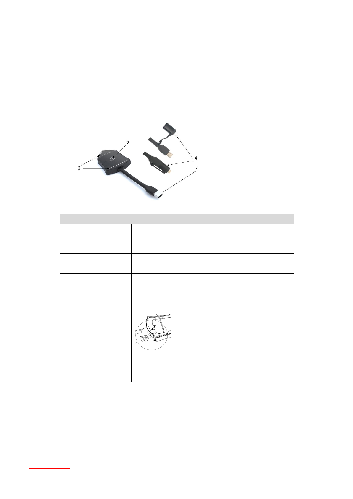
2.2 Sensor-Button TOUCH
ID
Name
Description
1
USB connector
- Connect to an USP-port of a PC/Laptop ( for sharing of screen)
- Pairing the Button to the Base-unit
- Updating of its software)
2
Sensor-button
TOUCH
Touch-function with tactile response,
for switching On and Off the presentation of the screen
3
Status LED
Indicates the status of the button
4
USB-C Adapter
(optional)
Adapter USB-C to USB-A (7488000304), for devices with USB-C
ports; can be permanently attached to the button
w/o
pic.
Closing flap
To close the hole after removing the USB-Token
w/o
pic.
USB-Token
USB-stick with Starter-program „WirelessMedia.*** “ for copying
of to PC or MAC; printable PDF of User manual.
The Klick & Show Sensor-button TOUCH is a dongle, which is used for extending or mirroring the desktop from a
personal PC or MAC desktop to the Base-unit and the main screen in a meeting. Newer (Mac) computers with
USB-C interface can be connected via an optional adapter (7488000304). Furthermore, the button can be
connected to the Base-unit to update the software or for pairing.
Handle the Button cable with care. Rough handling might cause defects.
Status LED
LED indicator is static green: ready to transmit a picture, waiting on USER for touch.
LED indicator is static red: 1. Transmits a picture,
2. Pairing is done (at the Base-unit). You can now unplug the Button
from the Base-unit.
LED indicator is flashing green: 1. The button is plugged in the laptop and initializing,
Table of contents
16
2.3 User Interface
ID
Name
Description
1
Wi-Fi-Indikator
Wi-Fi Direct mode: internal access point is enabled
Wi-Fi Infrastructure mode: „Client-Mode“ ,
Wi-Fi connection to router is established,
icon displays the current signal strength
A secure Wi-Fi connection is established, or connection to a
router failed:
Wi-Fi is not available: .
LAN Infrastructure mode: access point is disabled
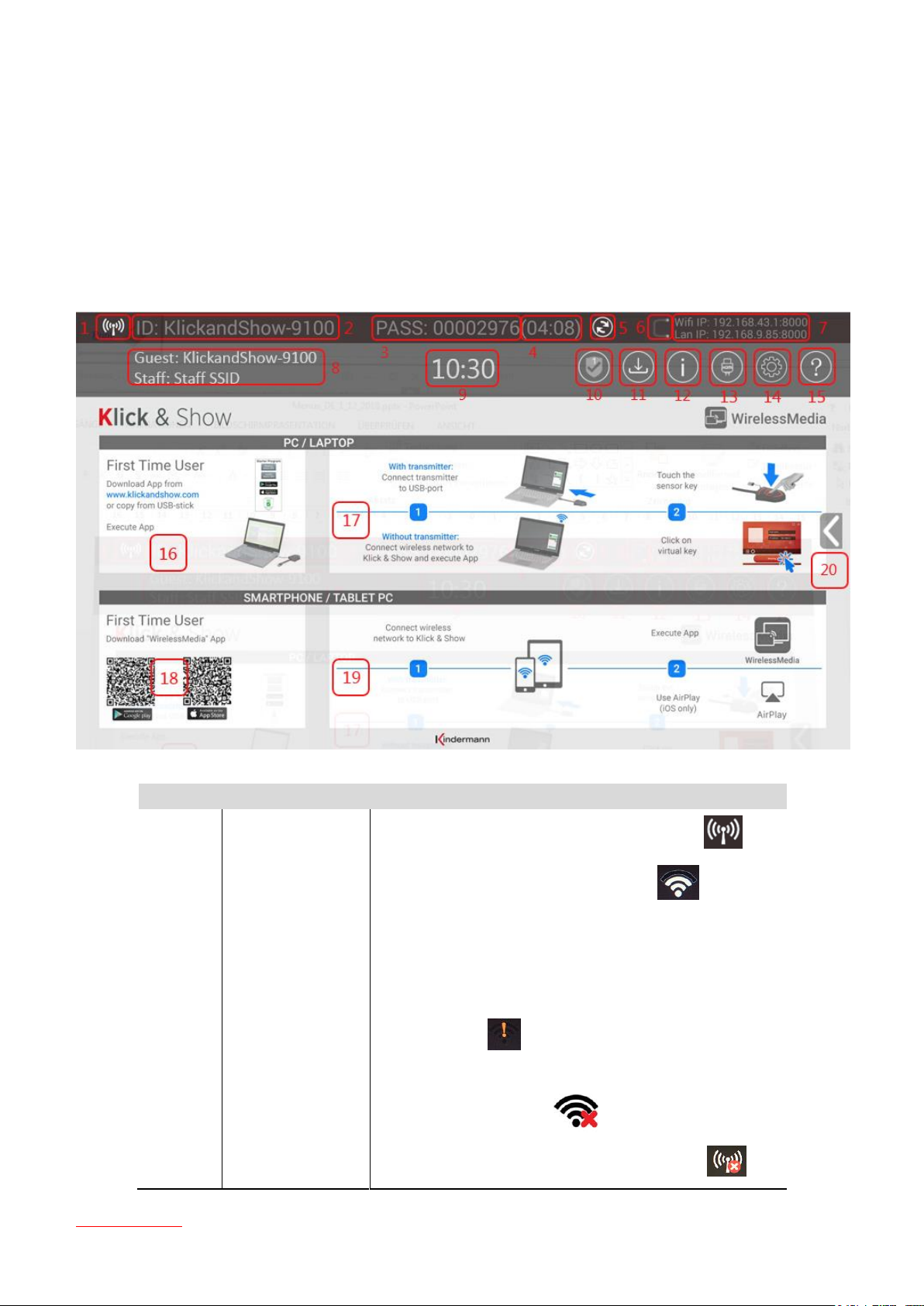
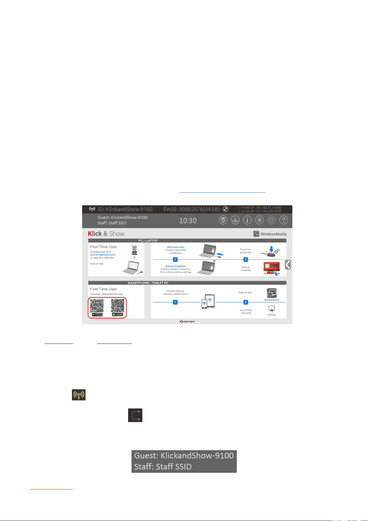
2.3.1 Home screen
The following picture shows Home screen of Klick & Show. Connect an input device (mouse, touch) to either USB
port to navigate in the menu.
Table of contents
17
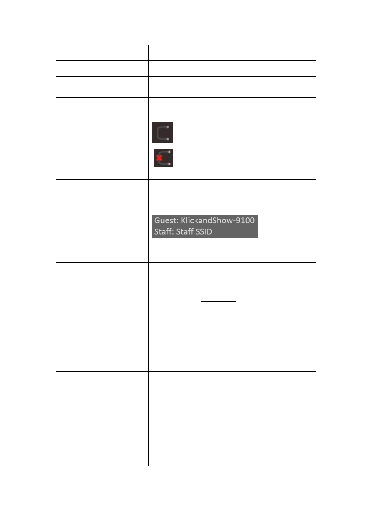
2
ID
Wi-Fi name or device name of the Base-unit access point
3
PASS
Wi-Fi-password of Base-unit
4
Password-timer
Is only displayed, when timer is active;
time until the password is changed automatically
5
Change
Wi-Fi-password
Generate new password manually for securing your Wi-Fi network,
for example to end the REMOTE-view function of mobile units
6
Status
Dual Netzwerk
(Wi-Fi + LAN)
: Connected Dual network (Wi-Fi + LAN)
: Segmented Dual network (Wi-Fi X LAN)
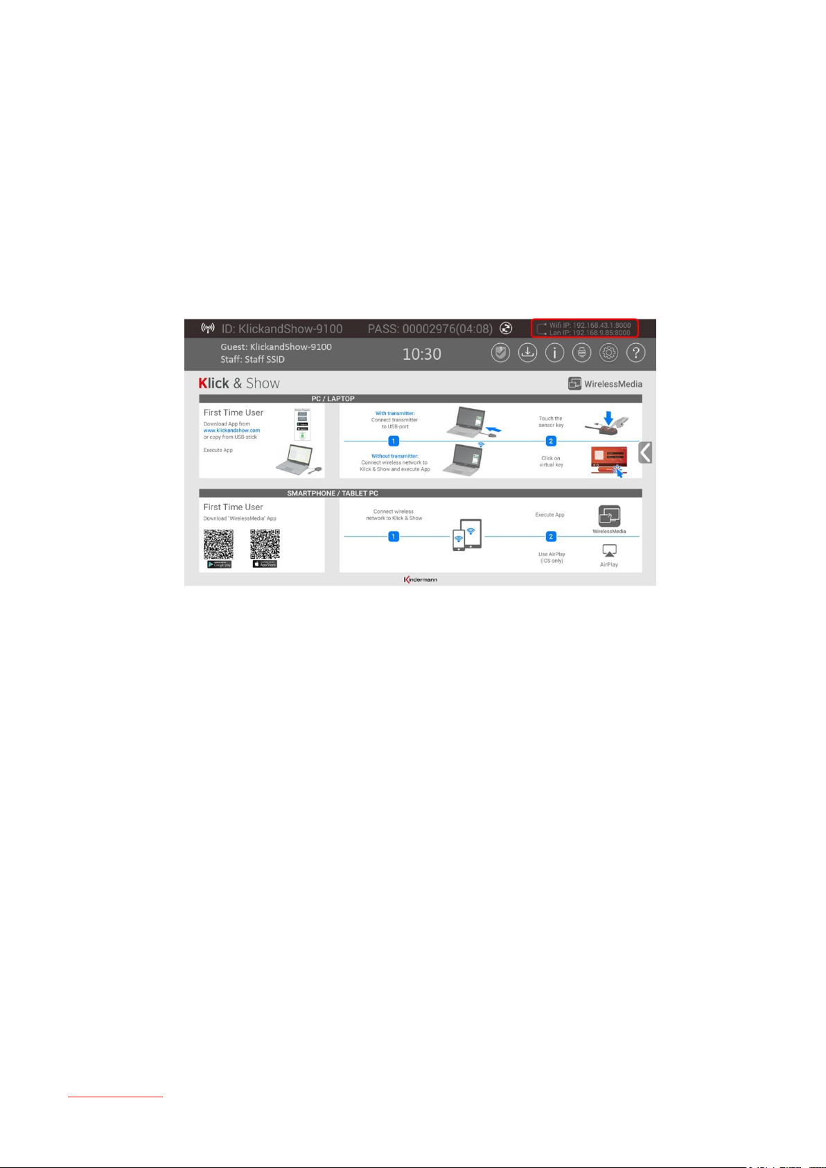
7
Wi-Fi IP
LAN IP
Wi-Fi IP-address of Base-unit in wireless LAN
Assigned IP-address of Base-unit in LAN;
„N/A“ = no connection to network
8
SSID: Guest
SSID: Staff
Name of Wi-Fi network for Guest and Staff, which allows mobile
devices to connect with the Base-unit
9
TIME
Show time, if LAN has access to a time server; even after
disconnecting the LAN connection, the time is displayed until the
device has been disconnected from power
10
Security level
Security level 1-3, display ONLY; the security features of the
displayed level are displayed in detail by clicking on the symbol;
the settings can only be changed by administrator in the Setting
menu (14)
11
Create Starter-
program
Copy Start-program „WirelessMedia.exe“ for Windows, MAC to
USB-stick
12
Info
Show status-bar (1) – (8) in Home screen showing/hiding
13
HDMI Input
Switch to the external HDMI input
14
Setting
Klick & Show system configuration
15
Help (?)
User manual in PDF format.
The current version of manual can also be downloaded from
the website www.klickandshow.com.
16
Windows / MacOS
Quick Start
First-time-user
First-time users must first install the starter program from the
web page www.klickandshow.com or from the USB stick one
time
Table of contents
18

17
Quick Guide
Windows / MacOS
Operating instructions for operation with laptop / Mac, with and
without transmitter TOUCH; First time users have to install starter
program once (16)
18
Load
„WirelessMedia“-
App from Store
Scan corresponding QR-code for iOS or Android device and
download the App from the Store
19
Android/IOS
Quick Start
First-time-user
Steps to instruct how to transmit smart mobile devices either
powered by Android or IOS, onto the main screen
20
Preview function of
the screen contents
of the participants
with TOUCH
transmitter
Switch on or off the optional preview function of the screen
contents of all connected TOUCH sensors.
Table of contents
19

3. Installation
3.1 Installation methods for the Base-unit
The Base-unit can be placed on a table in meeting room or be mounted on the wall.
To avoid damage during transport, the antennas are delivered unassembled. The antennas can rotate or tilt for
better wireless connection.
Note:
For optimum function, install the Base-unit near monitor. Avoid obstacles between Sensor-button TOUCH and
Base-unit.
Necessary tools
• A drill (type of drill depends on the type of wall/table)
• Flat screwdriver
• Additional screwdriver that matches the mounting screws (mounting screws not included in the package).
Necessary parts
• 2 mounting screws (the head of the screw has to be smaller than the whole of the bracket)
• 2 plugs fitting to Wall and Screws
• 2 mounting bracket (included in the box).
How to install
Drill two holes in the wall as indicated on the drawing. Horizontal distance: 177 mm ± 0.15.
At the bottom of Base-unit, place the bracket on the 4 holes and turn in four delivered flat screws to be
fasten enough.
Drive in 2 screws. Please leave at least a dimension 0.15mm space to place the bracket between the screw
header and wall.
Place the Base-unit on the wall, so that the holes on the bracket matches the 2 unfixed screws on the wall..
Hoop the bracket on the screw and slide the Base-unit downwards until it is fixed in the two screw on the
wall.
Table of contents
20
Antenna placement rules
The antennas should be oriented vertically.
The antennas should be installed far enough (at least 50cm/1.6ft) from metallic surfaces to avoid
unwanted reflections and far enough (at least 1m/3.3ft) from other radio equipment that operates in the
same frequency range, e.g. other Wi-Fi access points, cordless telephone, microwave ovens,…. It is also
best to install antennas at least 15 cm (6 inches) from concrete walls.
The most favorable situation is a direct line of sight between antennas and Sensor-buttons TOUCH. Any
obstruction will cause the signal to follow a longer propagation path, which can result in performance
degradation.
Due to the particular radio pattern of the dipole antennas, the antennas should not be placed just above
potential positions of Sensor-buttons users. As a result, the advised position for the obstruction antennas
is at the side of the meeting room.
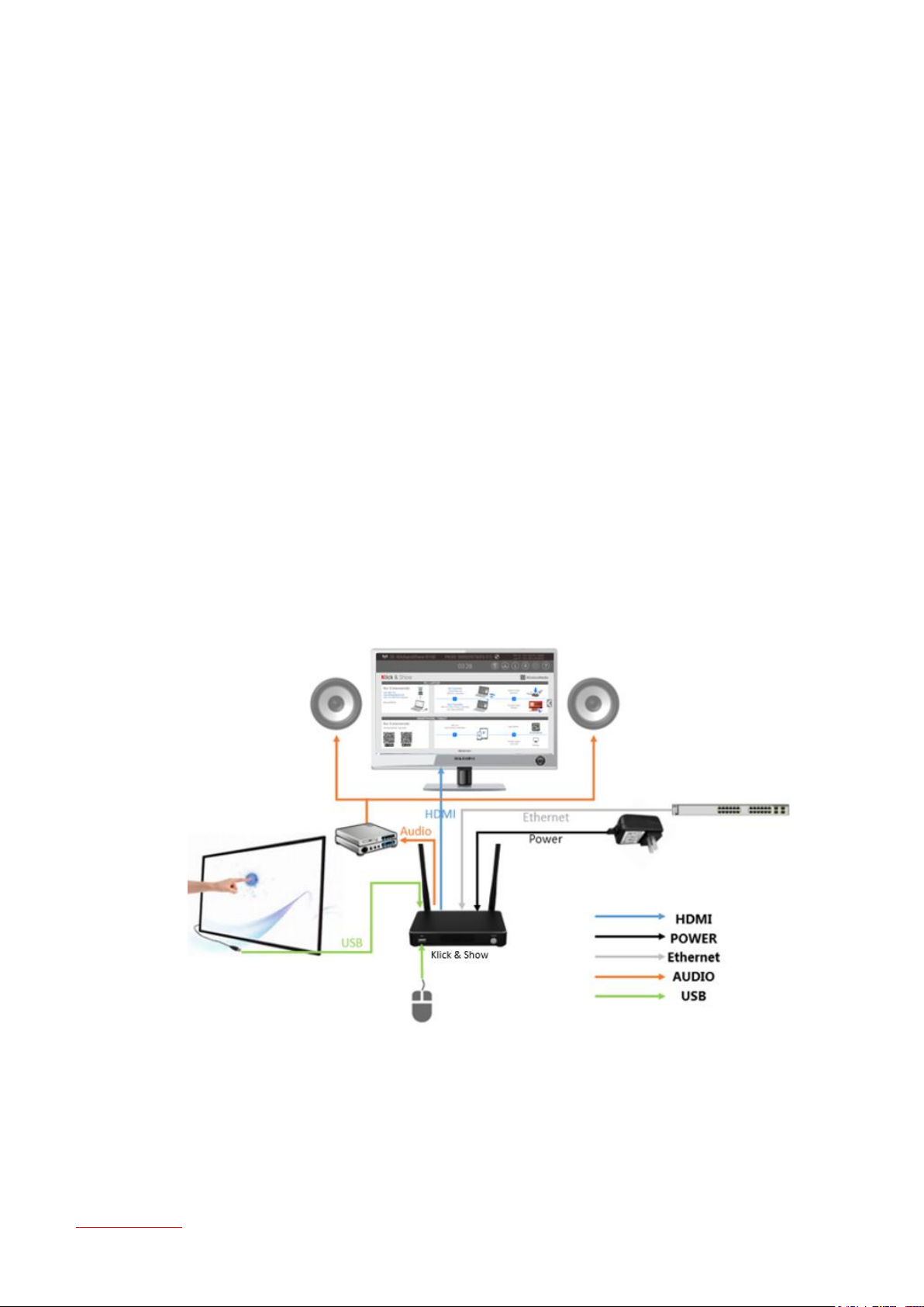
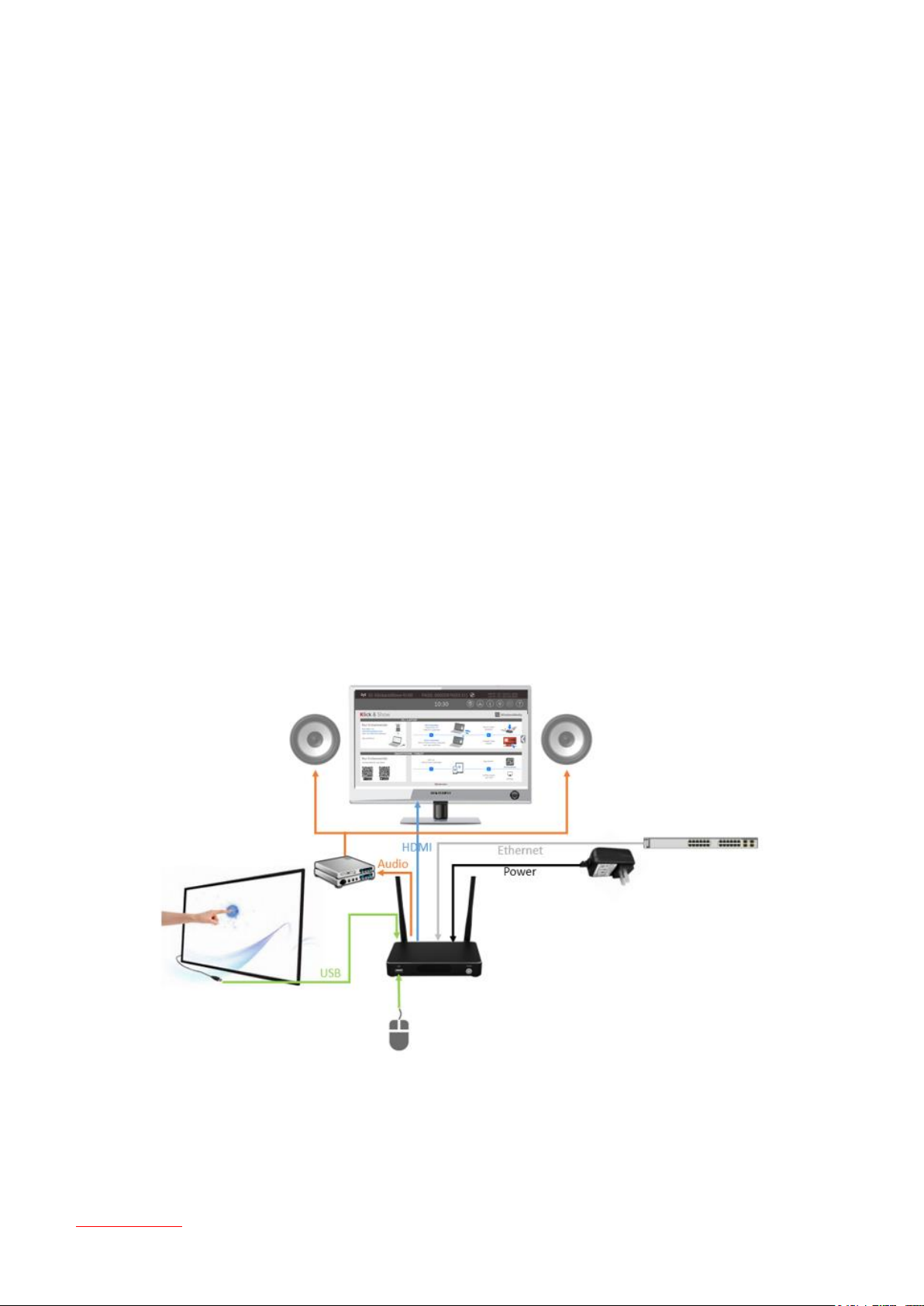
3.2 Wiring Diagramm Base-unit
Cabling of equipment
3.3 Power Connection
Supplied is a universal power supply for mains 100 – 240 VAC, 12 VDC/2A with different, regional power
Table of contents
21

adapters.
Adapter types
1. Choose the appropriate power plug for your country (see www.iec.ch/worldplugs.) and slide it in power
supply
2. Connect the power adapter with the Base-unit.
3. Connect the power cable plug into the wall outlet.
TYP A (USA, Japan) Typ C (EU, except UK) Typ G (UK etc.) Typ I (Australia)
Note:
Once the Base-unit is powered, it starts up (booting). From now on please use the POWER button with Status LED
on front of Base-unit to switch ON or OFF.
Power over Ethernet
If the LAN Ethernet switcher support PoE (Power over Ethernet), it could power up the Base-unit instead of using
the external power adapter.
3.4 Video Connection
1. Connect the HDMI-Output of Base-unit to a Full-HD-/4K display by a quality HDMI cable.
2. Switch the Base-unit ON.
3. After started, the system shows the Home screen.
Table of contents
22
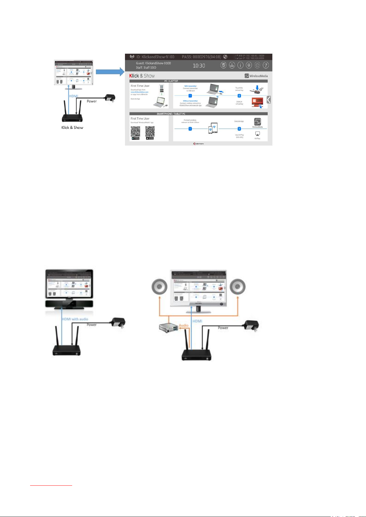
3.5 Audio Connection
The Wi-Fi of Sensor-button TOUCH transmits the audio output of the PC/Laptop, re-direct and send to the Baseunit together with the video signal. The audio will be output at line levels from mini jack socket 3.5 mm
connector and via the HDMI output connectors simultaneously.
Audio via HDMI output
When your display/projector is connected via HDMI and it support audio together with video than a separate
audio connection is not necessary. The audio signal is sent together with the video signal to the display.
Note:
If there is no sound from speaker check the settings of volume-mixer in taskbar of laptop, “WirelessMedia” or
“Video-Playback” must be activated.
Audio Output
Connect the analog audio “LINE OUT” (mini Jack 3.5mm) of the Base-unit with the meeting room’s sound system
by using a fitting cable.
PC/Laptop Sound
Table of contents
23
As default set, Klick & Show will mute the internal speaker of PC/Laptop and route the audio to the Base-unit,
after PC/Laptop is successfully mirroring desktop to the main screen, in order to avoid the repeated audio. When
transmission is stopped at Sensor-button, local loudspeaker will return to previous status.
Note:
If there is no sound, it can have different causes, for example:
1 Check the volume control on your laptop's taskbar; see in "Mixer" if "WirelessMedia" or "Video Playback" is
activated. To keep the internal speaker of PC/Lap muted while route the audio to the Base-unit, use the
audio mute icon in the status bar.
2 The used video-player may need an update to latest version.
3 An active virus scanner can block the sound reproduction, check the "settings" in your virus scanner, and
check the influence by turning off the virus scanner.
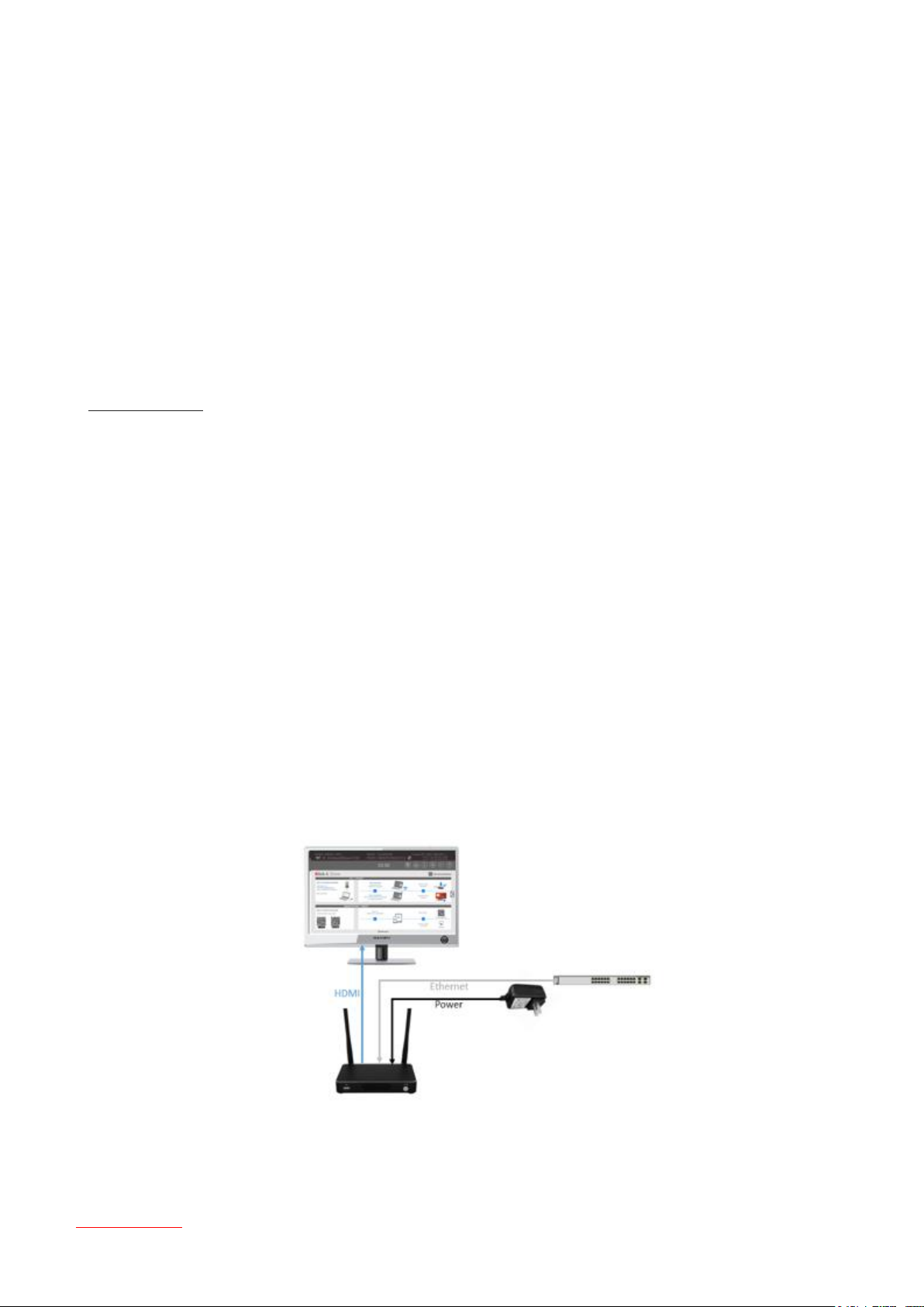
3.6 LAN Connection
The Base-unit can be connected to a local network or directly to a PC/Laptop. For normal operation, a LAN
connection is not necessary. When needed, it is suggested to connect the Klick & Show to the internet.
The LAN connection can be used for:
network integration of Base-unit in guest or company network
telnet control of the Base-unit
Table of contents
24
Over-The-Air -Update (OTA) of firmware of Base-unit
maintenance purpose (in preparation)
Telnet commands
Telnet is a relatively simple, text-based protocol by which a computer of another person can connect via internet
to Klick & Show. Control via TCP/IP (port 5656) is possible. You can find the list of commands in chapter 8.
LAN indicator
LAN “connected” or “disconnected” is shown briefly in a message in lower/right corner on the Home screen.
3.7 Usage of USB device
Please use a USB Mouse or Touchscreen:
1. For configuration of Klick & Show,
2. To control the sharing PC/Laptop („Remote-Control“ can be blocked in settings),
3. For white board or annotation during a presentation, Klick & Show transmits Video, Audio and the USB-
HID function for mouse-control and click-function of a touchscreen. Connect touch-interface of your
screen to the USB-port on your laptop or PC.
4. To run a system upgrade.
USB control
USB mouse for configuration menu
Table of contents
25
Single click to select
Right-click to back to the Home screen
Touchscreen
Single click to select
Long press to open the contextual menus, as double-click or click the right button of a USB mouse.
4. Getting started with Klick & Show
4.1 Mobile units: Wireless Connection
Download the application namely “WirelessMedia” (for example scan QR-Code in Home screen) in Android Play
Store or Apple App Store or download it from website https://www.klickandshow.com/ .
After unpacking or after Factory reset, Klick & Show starts in standard configuration "Wireless Direct Mode"
("Linked Single Network"), where the base unit creates its own wireless access point, to which all the TOUCH
buttons connect. This is typical for quick setup, temporarily installations or for small business meetings with a
small number of meeting rooms.
The Wi-Fi icon for "WiFi Direct Mode" appears in the top status bar of the Home screen. The "Connected
Dual Network (LAN + WLAN)" icon appears in the top status bar in front of the Wi-Fi and LAN address.
The SSIDs for these hotspots appear in the Start screen of Klick & Show:
Table of contents
26
Guests and staff have access to the internet when LAN is enabled, see 4.1.1.
Further options of the configuration for integration into a company network are provided in section 5.1.
4.1.1 Enable portable access point:
Make sure Klick & Show is connected to the network. If a local address is displayed on the Home screen, this
means: the base device is correctly integrated in the LAN and has received an IP.
Note:
When it shows “N/A”, means the Base-unit is not connected to the LAN by by CAT cable. This may be desirable or
the connection failed or got an available IP address by the corporation router.
For basic function, a LAN connection is not needed.
Please refer to the LAN-settings in ‘Ethernet, as below.
Default password for entering the Main menu is “admin”.
4.2 Pairing Sensor-button with Base-unit
Connect the USB-connector of Sensor-button TOUCH to either of one USB port of Base-unit, to pair both units at
same Wi-Fi. Follow all OSD messages. A successful pairing is shown at OSD and static red LED.
Table of contents
27

Then, please disconnect the Sensor-button TOUCH and use it for the mirroring on your laptop.
Pair all other buttons in the same way.
If error-message “Configuration fail” is shown, please check the connection of USB to keep stable after plug-in,
and try again.
Note:
After each changing the SSID/Wi-Fi channel in menu, all the Sensor-buttons TOUCH must be paired again!
When you buy additional Buttons or when a Button should be assigned to another Base-unit, the Button
must be paired again.
A Button can only be paired to one Base-unit at a time. The Button will always make connection to the Base-unit it
was last paired to.
Table of contents
28
4.3 Mirroring of the desktop - First steps
More detailed instructions for operation can be found in chapter 6.1
4.3.1 PC / Laptop
When you are using Klick & Show for the first time on your laptop or for guests, you have to copy the Starterprogram first on your Laptop / PC. Run this Starter-program.
When the Starter-program is pre-installed one time, with plugging-in of the Sensor-button TOUCH, Klick
& Show is ready to use, continue with step 6.
There are four possibilities for loading and executing the Starter-App „WirelessMedia-windows“ for Windows,
or „WirelessMedia-macOS“ for Apple:
1. The best and safest way: download the App via LAN or Wi-Fi of Base-unit, enter IP-address (3) of
status-bar of Home screen in a browser, download „WirelessMedia for Windows“, or „WirelessMedia for
MAC“, continue with 5.
2. Download App from Internet www.klickandshow.com , continue with 5.
3. Store APP on a USB-stick at Base-unit: plug a USB-stick to USB port of Base-unit and copy Start-
program „WirelessMedia.exe“ to USB-stick by clicking on symbol , continue with 5.
4. Copy the App from enclosed USB-token to the PC.
Execute the *.exe file.
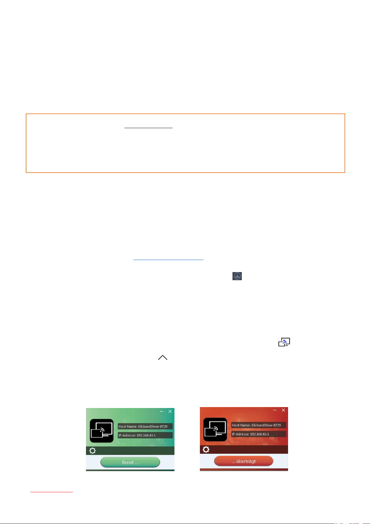
5. Plug a Sensor-button TOUCH to the USB port of your PC or Laptop. The Klick & Show application is
starting automatically and a symbol is displayed in the task bar of the PC/laptop .
(You may need to click the up arrow in the task bar, to view the icon.)
6. Till the transmitter button shows a static green LED indicator, or till you see a message table showing up
at the right bottom corner of desktop “Ready to share”.
Table of contents
29
7. Click the Sensor-button or with mouse the symbol at screen, to start mirroring the desktop on the main
screen, LED is static red. An OSD message shows: logged in user name (option) and status of “Remote
Control” and “Remote View” of desktop (locked/unlocked).
8. Click the Sensor-button again, to stop mirroring, LED shows green again.
9. Disconnect the Sensor-button at end of meeting.
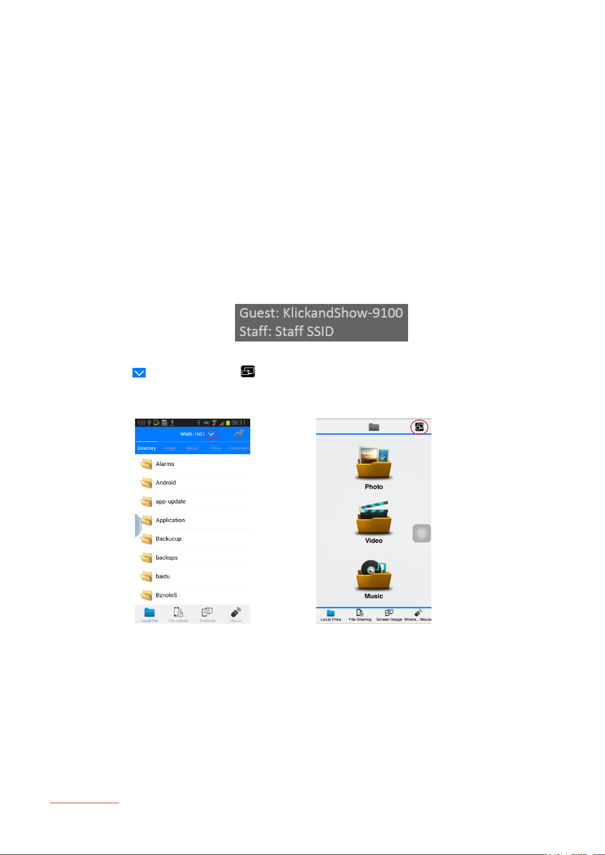
4.3.2 Mobile Devices
More detailed instructions for operation can be found in chapter 6.2.
1. Connect your mobile device to one of the displayed Wi-Fi networks:
2. Connect your Mobile with the LAN of Klick & Show. Open the App “WirelessMedia” on your phone. Press
symbol “ ” for Android, or “ ” for iOS in start page, to get a list of available devices of Klick &
Show.
Android iOS
Table of contents
30
 Loading...