


TOS5101
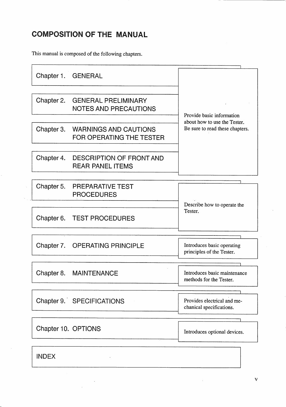
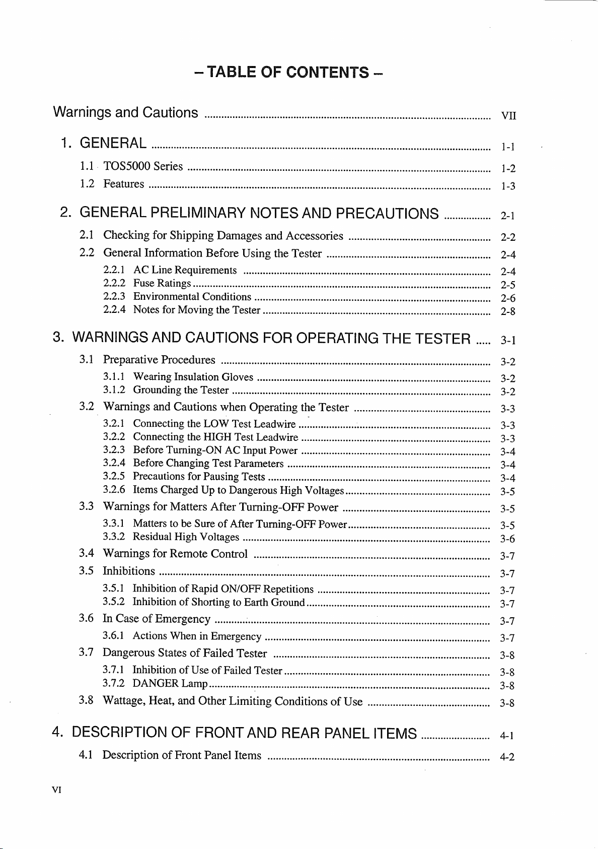
Table of contents
 Loading...
OPERATION MANUAL
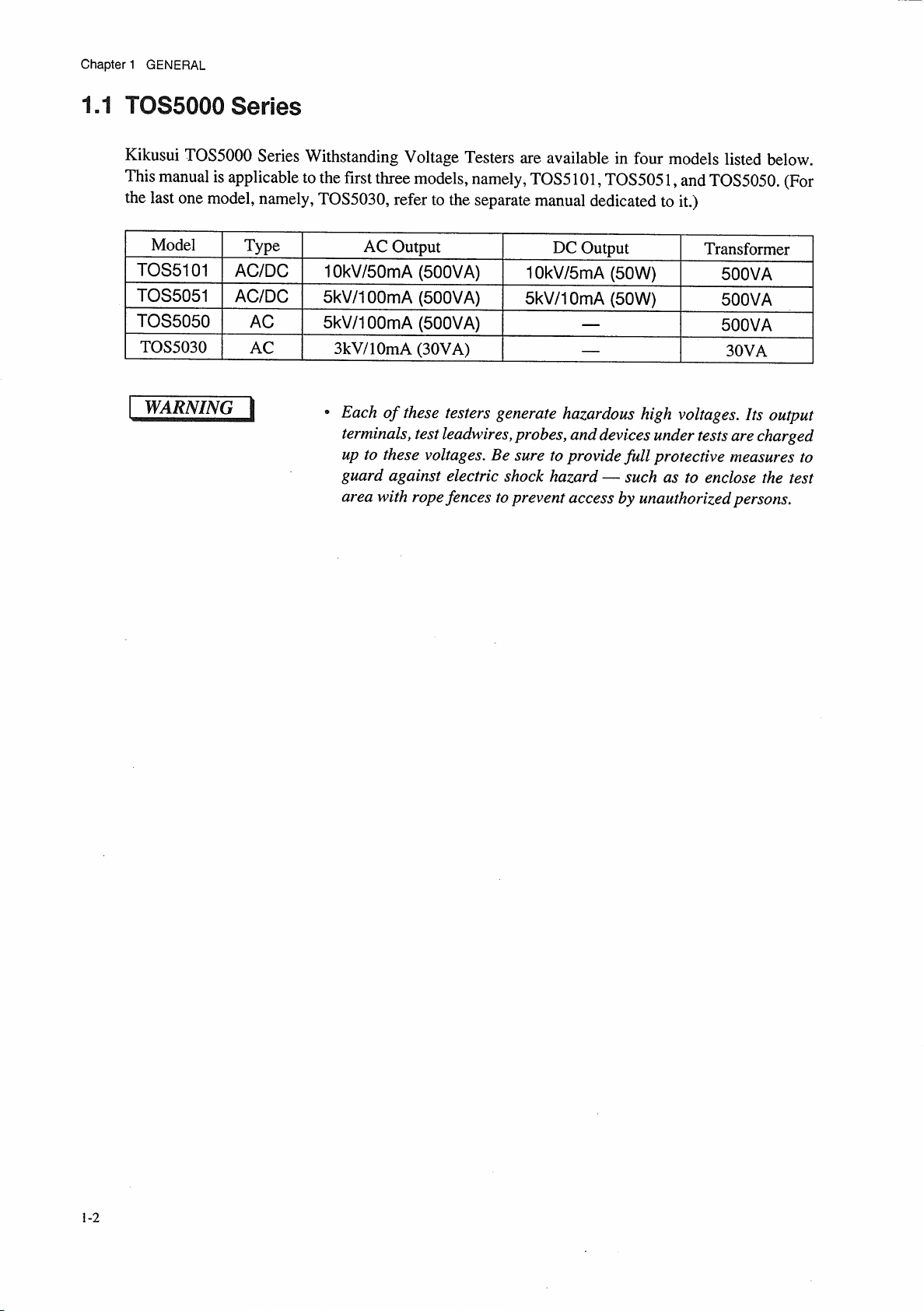
TOS5000 SERIES
WITHSTANDING VOLTAGE TESTER
TOS5101
TOS5051
TOS5050
DANGER
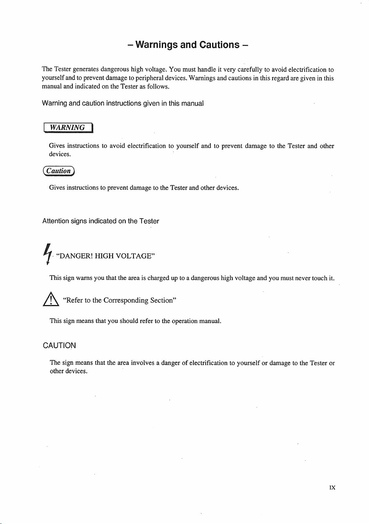
WARNINGS Against HIGH VOLTAGE
• This Tester generates high voltage.
• Any incorrect handling may cause death.
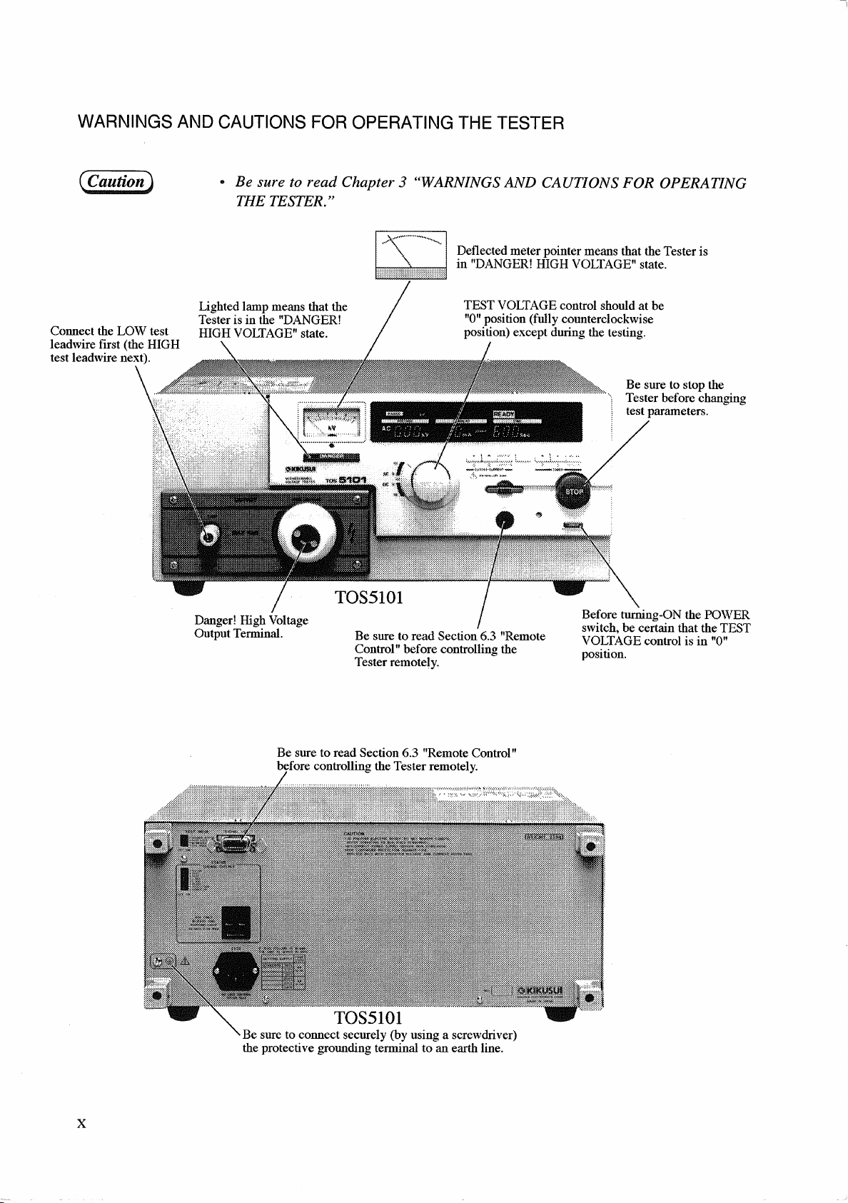
• Read Chapter 3 "WARNINGS AND CAUTIONS FOR OPERATING THE TESTER"
in this manual to prevent accident.
• This manual should be placed within the reach of the operator so that he or she
may read it whenever necessary.
PartNo.Z1-000-632IB000598,MAR/2004

All or any parts of this manual may not be reproduced in any forms, without express written
permission of Kikusui Electronics Corporation.
The contents of this manual, including the specifications of the instrument, are subject to change
without notice.
©1993-2004 Copyright Kikusui Electronics Corporation.
Printed in Japan. All rights reserved.


4.1.1 Turning ON/OFF the AC Input Power ................................................................ 4-3
4.1.2 Start/Stop of Test .................................................................................................. 4-5
4.1.3 Test Voltage .......................................................................................................... 4-9
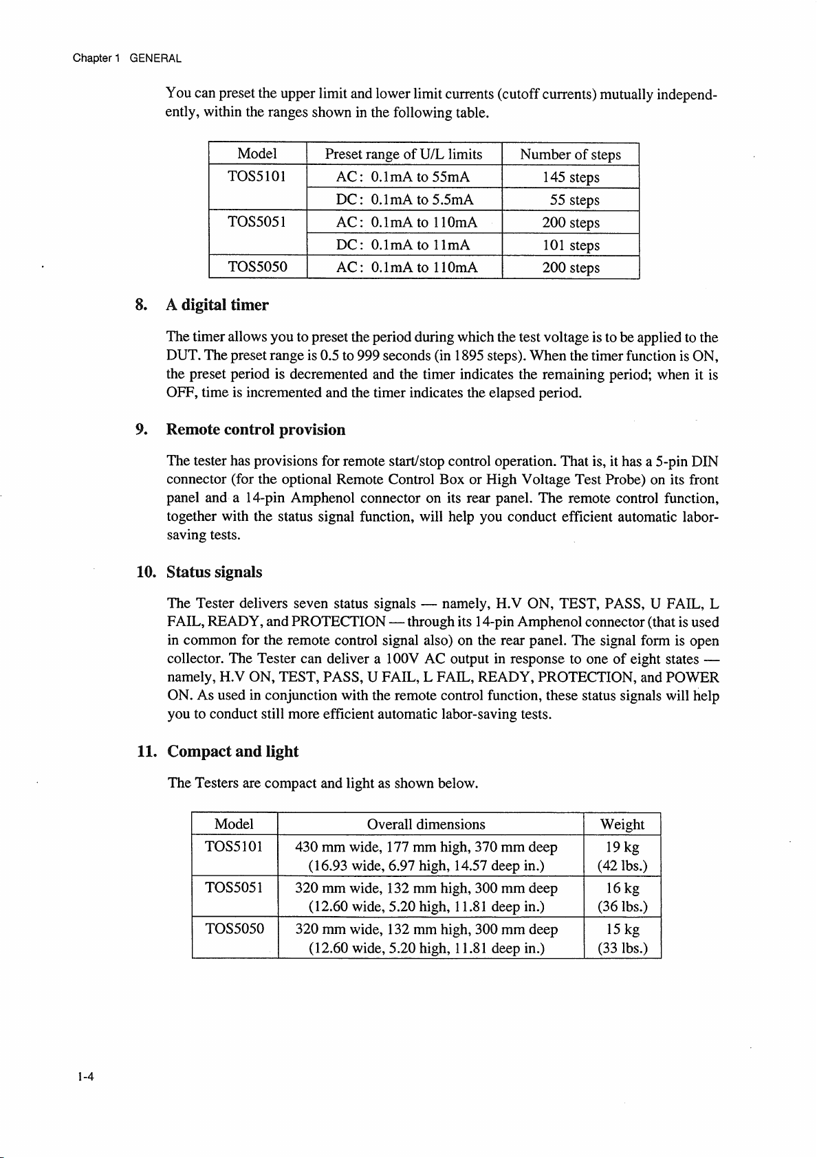
4.1.4 Cutoff Currents ..................................................................................................... 4-12
4.1.5 Test Time .............................................................................................................. 4-15
4.1.6 Others .................................................................................................................... 4-17
4.2 Display Items ................................................................................................................ 4-18
4.2.1 Test Voltage Display ............................................................................................. 4-18
4.2.2 Readout for Cutoff Current and Measured Current .............................................. 4-21
4.2.3 Test Time Display ................................................................................................. 4-23
4.2.4 READY Message .................................................................................................. 4-24
4.2.5 TEST Message ...................................................................................................... 4-24
4.2.6 PASS Message ...................................................................................................... 4-24
4.2.7 FAIL Messages ..................................................................................................... 4-24
4.2.8 PROTECTION Message ....................................................................................... 4-25
4.2.9 Others .................................................................................................................... 4-25
4.3 Description of Rear Panel Items ................................................................................. 4-26
5. PREPARATIVE TEST PROCEDURES .............................................................. 5-1
5.1 Initial Setup ................................................................................................................... 5-2
5.1.1 Initial Setup of Switches and Controls .................................................................. 5-2
5.1.2 Initial Test Setup Data........................................................................................... 5-2
5.1.3 Procedure for the Initial Test Setup Data .............................................................. 5-3
5.2 Checking the Tester Operation ................................................................................... 5-4
5.3 Checkout Before Starting Test Operation ................................................................. 5-6
6. TEST PROCEDURES .................................................................................................. 6-1
6.1 AC Withstanding Voltage Test Procedure ................................................................ 6-2
6.1.1 Selecting an AC Test Voltage Range .................................................................... 6-2
6.1.2 Setting the Upper Cutoff Current .......................................................................... 6-3
6.1.3 Setting the Lower Cutoff Current ......................................................................... 6-4
6.1.4 Setting the Test Time ............................................................................................ 6-5
6.1.5 Setting the Test Voltage ........................................................................................ 6-6
6.1.6 Connecting the DUT ............................................................................................. 6-7
6.1.7 Executing a Test .................................................................................................... 6-7
6.2 DC Withstanding Voltage Test Procedure ................................................................. 6-12
6.2.1 Selecting a DC Test Voltage Range ...................................................................... 6-12
6.2.2 Setting the Upper Cutoff Current .......................................................................... 6-13
6.2.3 Setting the Lower Cutoff Current ......................................................................... 6-14
6.2.4 Setting the Test Time ............................................................................................ 6-16
6.2.5 Setting the Test Voltage ........................................................................................ 6-17
6.2.6 Connecting the DUT ............................................................................................. 6-17
6.2.7 Executing a Test .................................................................................................... 6-18
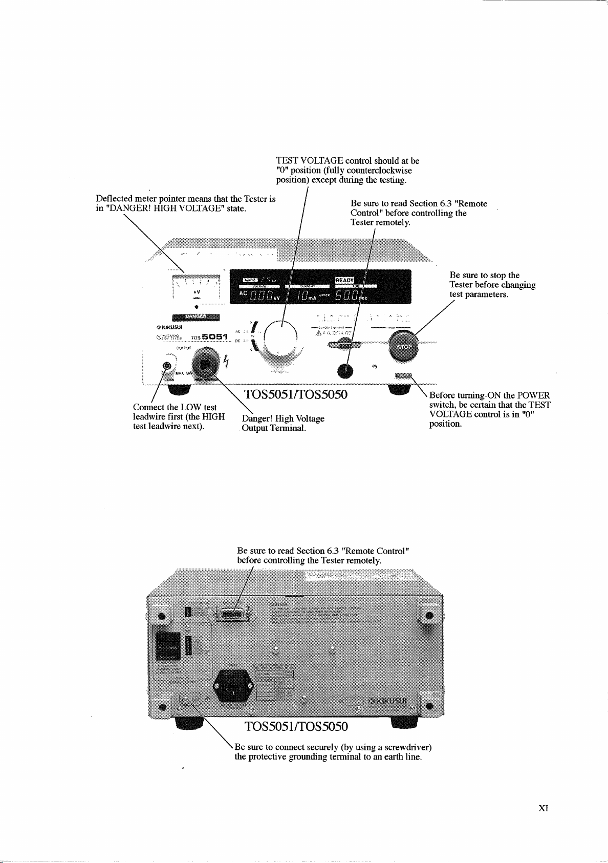
6.3 Remote Control .............................................................................................................. 6-22
6.3.1 Remote Control through REMOTE CONTROL Connector................................. 6-23
6.3.2 Remote Control through SIGNAL I/O connector ................................................. 6-24
6.3.3 Interlock Function ................................................................................................. 6-26
VII

6.4 Output Signals ................................................................................................................ 6-27
6.4.1 Output Signals of SIGNAL I/O Connector ........................................................... 6-27
6.4.2 Output Signal of STATUS SIGNAL OUTPUT receptacle .................................. 6-30
6.5 Settings for Special Test Modes ................................................................................. 6-31
6.5.1 DOUBLE ACTION Switch .................................................................................. 6-31
6.5.2 PASS HOLD Switch ............................................................................................. 6-31
6.5.3 MOMENTARY Switch ........................................................................................ 6-32
6.5.4 FAIL MODE Switch ............................................................................................. 6-32
7. OPERATING PRINCIPLE .......................................................................................... 7-1
7.1 Block Diagrams ............................................................................................................ 7-2
7.2 Componential Circuits and Devices .......................................................................... 7-3
7.3 Zero-turn-on Switch ..................................................................................................... 7-4
7.4 Delay Time for Pass/Fail Judgement in DC Mode .................................................. 7-5
7.5 Automatic Discharge Function ................................................................................... 7-5
8. MAINTENANCE ............................................................................................................... 8-1
8.1 Cleaning the Outer Surfaces ....................................................................................... 8-2
8.2 Checking the Cord and Leadwires ............................................................................. 8-2
8.2.1 Checking the AC Power Cable ............................................................................. 8-2
8.2.2 Checking the HV Test Leadwires ......................................................................... 8-2
8.2.3 Overhaul ................................................................................................................ 8-3
8.3 Calibration ..................................................................................................................... 8-3
9. SPECIFICATIONS .......................................................................................................... 9-1
9.1 TOS5050 ........................................................................................................................ 9-2
9.2 TOS5101 and TOS5051 .............................................................................................. 9-9
9.3 Overall Dimensions ...................................................................................................... 9-18
9.3.1 Dimensions of Models TOS5050 and TOS5051 .................................................. 9-18
9.3.2 Dimensions of Model TOS5101 ........................................................................... 9-18
10. OPTIONS .......................................................................................................................... 10-1
10.1 Model RC01-TOS/RC02-TOS Remote Control Box ........................................... 10-2
10.2 Model HP01A-TOS/HP02A-TOS High Voltage Test Probe ............................... 10-3
10.3 Model PL01-TOS Warning Light Unit ................................................................... 10-4
10.4 Model BZ01-TOS Buzzer Unit ................................................................................ 10-4
10.5 High Voltage Test Leadwires ................................................................................... 10-4
INDEX ............................................................................................................................................ I-1
VIII

Chapter 2 GENERAL PRELIMINARY NOTES AND PRECAUTIONS
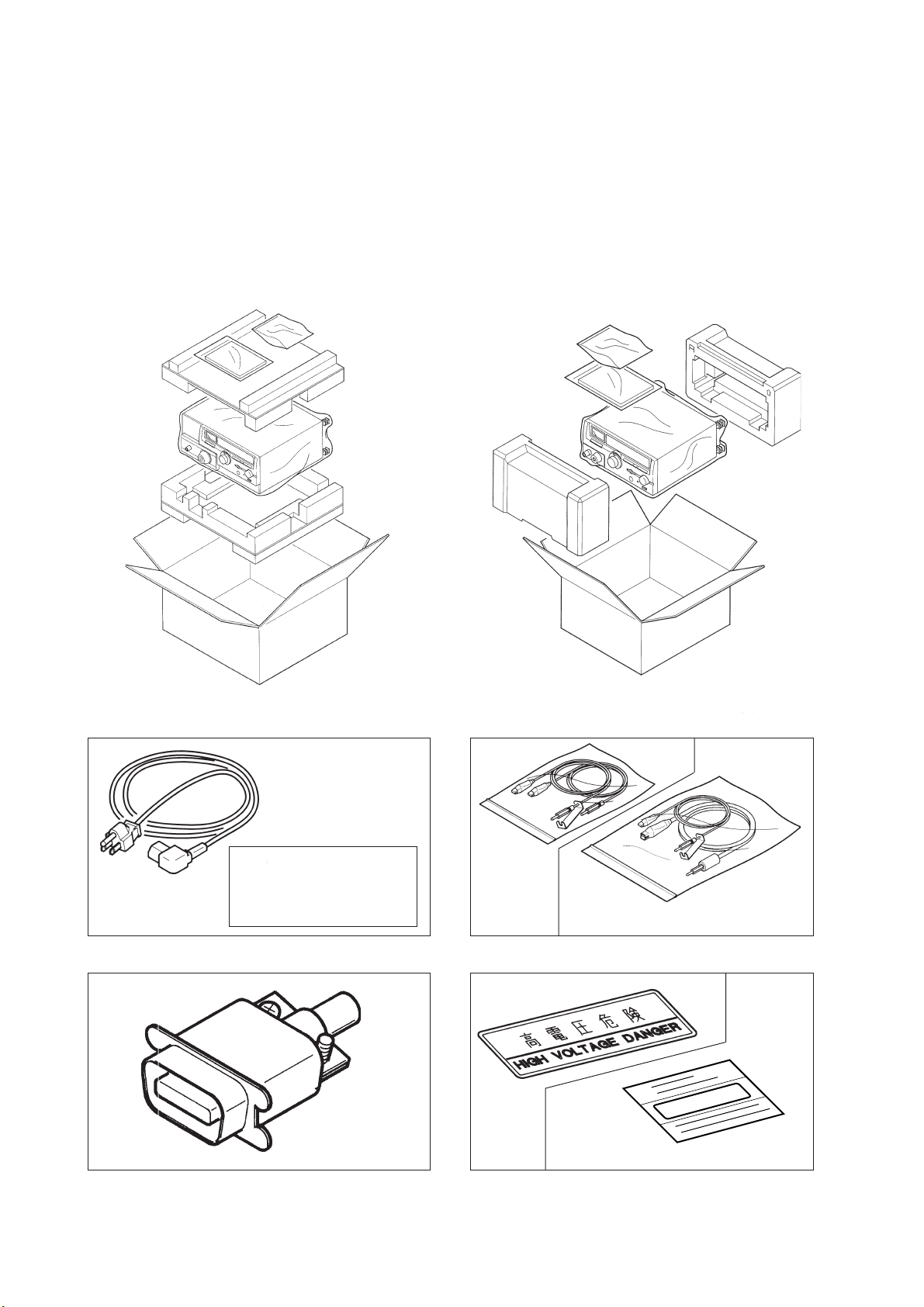
2.1 Checking for Shipping Damages and Accessories
When you receive the Tester, inspect it for any obvious damages that may have occurred during
shipment. Immediately report any damages to the carrier and your Kikusui agent.
You should also find the standard accessories as shown below accompany the Tester in the same
package.
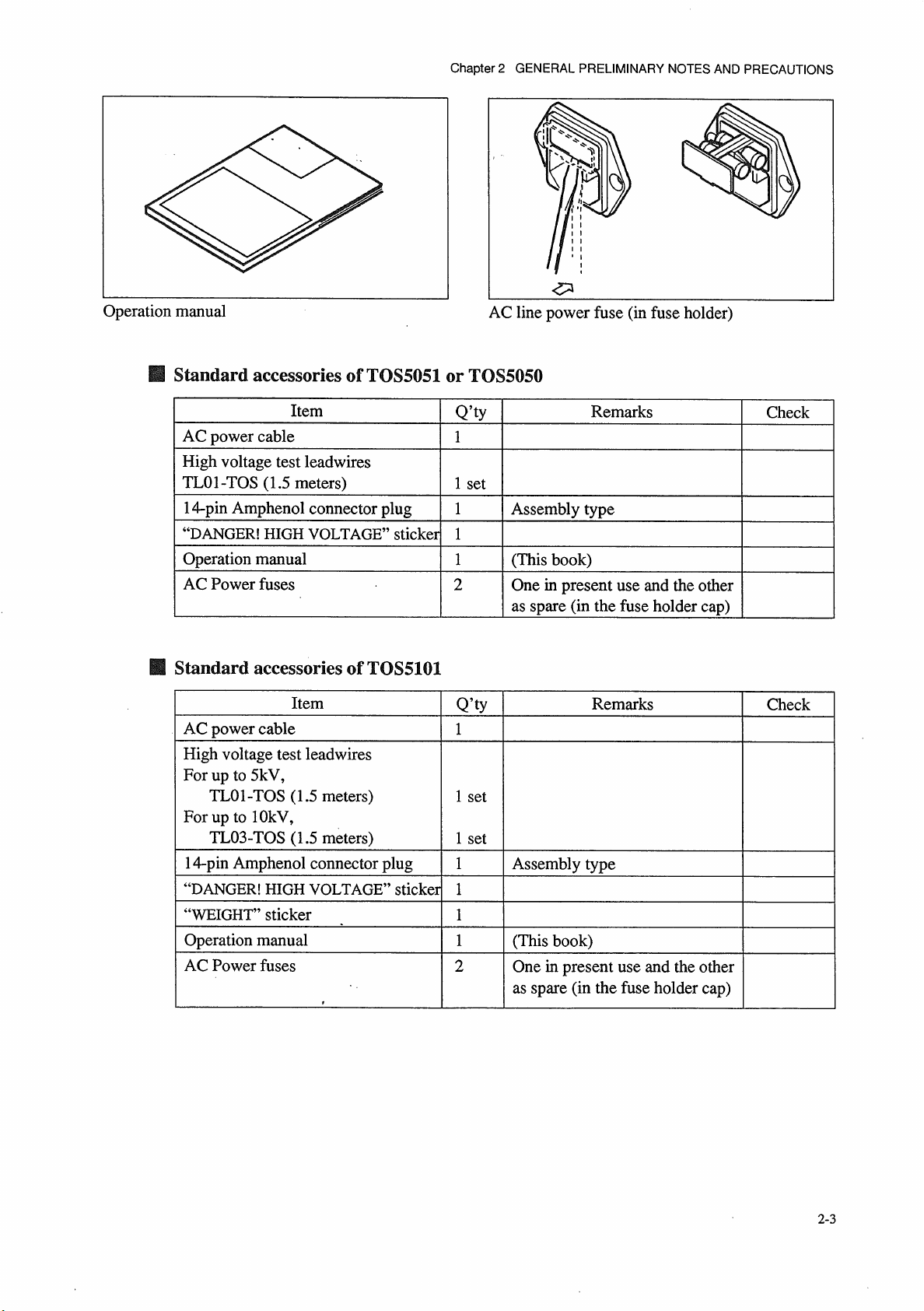
TOS5101 TOS5050/TOS5051
Do not use the AC power
cable attached to this
product for the AC power
cable of other instruments.
TL01-TOS
AC power cable HV Test Leadwires
TL03-TOS
(TOS5101 only)
○○kg
WEIGHT
(TOS5101 only)
14-pin Amphenol plug (assembly type) DANGER and WEIGHT sticker
2-2

Chapter 2 GENERAL PRELIMINARY NOTES AND PRECAUTIONS
2.2.3 Environmental Conditions
Be sure to observe the following precautions when installing the tester.
■ Do not use the tester in a flammable atmosphere.
To prevent explosion or fire, do not use the tester near alcohol, thinner, or other combustible
materials, or in an atmosphere containing such vapors.
■ Avoid locations where the tester is exposed to high temperatures or direct
sunlight.
Do not locate the tester near a heater or in areas subject to drastic temperature changes.
Operating temperature range: 0 ˚C to +40 ˚C
Storage temperature range: -20 ˚C to +70 ˚C
■ Avoid humid environments.
Do not locate the tester in a high-humidity environment-near a boiler, humidifier, or water supply.
Operating humidity range: 20 % to 80 % RH
(no dew condensation permitted)
Storage humidity range: 80 % RH or less
(no dew condensation permitted)
Condensation may occur even within the operating humidity range. In that case, do not start using the
tester until the location is completely dry.
■ Do not place the tester in a corrosive atmosphere.
Do not install the tester in a corrosive atmosphere or one containing sulfuric acid mist or the like. This
may cause corrosion of various conductors and imperfect contact with connectors, leading to
malfunction and failure, or in the worst case, a fire.
■ Do not locate the tester in a dusty environment.
Dirt and dust in the tester may cause electrical shock or fire.
■ Do not use the tester where ventilation is poor.
Prepare sufficient space around the tester to allow for air flow.
■ Do not place the tester on a tilted surface or in a location subject to
vibrations.
If placed on a non-level surface or in a location subject to vibration, the tester may fall, resulting in
damage and injury.
■ Do not use the tester in locations affected by strong magnetic or electric
fields.
Operation in a location subject to magnetic or electric fields may cause the tester to malfunction,
resulting in electrical shock or fire.
2-6

Chapter 2 GENERAL PRELIMINARY NOTES AND PRECAUTIONS
■ Do not use the tester in locations near a sensitive measuring instrument or
receiver.
Operation in a location subject, may cause such equipment may be affected by noise generated by the
tester. At a test voltage exceeding 3 kV, corona discharge may be generated to produce substantial
amounts of RF broadband emissions between grips on the test leadwire. To minimize this effect,
secure a sufficient distance between alligator clips.
In addition, keep the alligator clips and test leadwire away from the surfaces of conductors (particularly
sharp metal ends).
■ Secure adequate space around the power plug.
Do not insert the power plug to an outlet where accessibility to the plug is poor. And, do not place
objects near the outlet that would result in poor accessibility to the plug.
2-7

Chapter 2 GENERAL PRELIMINARY NOTES AND PRECAUTIONS
2.2.4 Notes for Moving the Tester
When moving the tester to the installation site or otherwise transporting it, take the following
precautions:
■ Before moving the tester, turn off the power switch.
Transporting the tester with its POWER switch on can lead to electric shock and damage.
■ When moving the tester, Disconnect all wires from it.
Moving the tester without disconnecting the cables may result in breakage of the wire or injury due to
the tester tipping over.
■ For transportation, use the special packing material for the tester.
Transport the tester in its original package to prevent vibration and falls, which may damage the
tester. If you require packing material, contact Kikusui distributor/agent.
■ Have two or more people move the tester.
The TOS5101 weighs approximately 21 kg. Two persons are required to carry the TOS5101.
Take extreme care when moving the TOS5101.
2-8
 Loading...