

Page 1
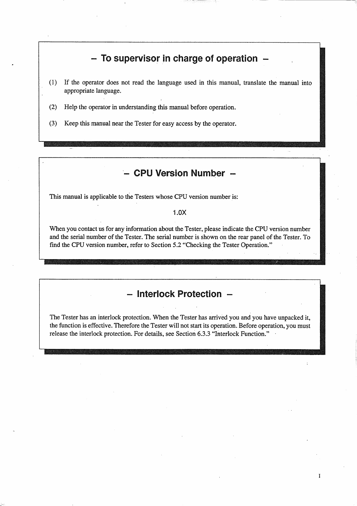
OPERATION MANUAL
TOS5000 SERIES
WITHSTANDING VOLTAGE TESTER
TOS5101
TOS5051
TOS5050
DANGER
WARNINGS Against HIGH VOLTAGE
• This Tester generates high voltage.
• Any incorrect handling may cause death.
• Read Chapter 3 "WARNINGS AND CAUTIONS FOR OPERATING THE TESTER"
in this manual to prevent accident.
• This manual should be placed within the reach of the operator so that he or she
may read it whenever necessary.
PartNo.Z1-000-632IB000598,MAR/2004
Page 2

All or any parts of this manual may not be reproduced in any forms, without express written
permission of Kikusui Electronics Corporation.
The contents of this manual, including the specifications of the instrument, are subject to change
without notice.
©1993-2004 Copyright Kikusui Electronics Corporation.
Printed in Japan. All rights reserved.
Page 3
Page 4
Page 5
Page 6

Page 7
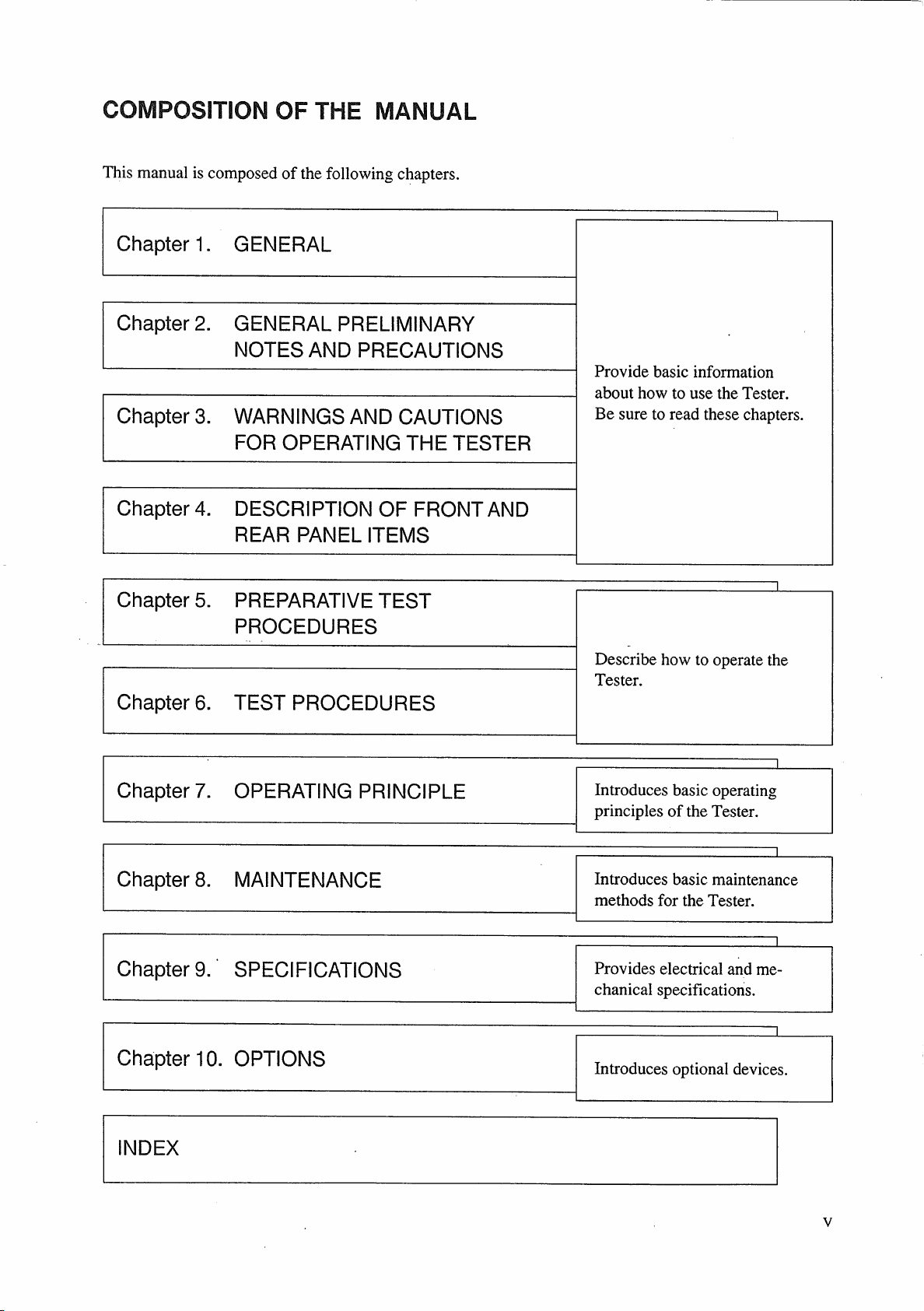
Page 8
Page 9

4.1.1 Turning ON/OFF the AC Input Power ................................................................ 4-3
4.1.2 Start/Stop of Test .................................................................................................. 4-5
4.1.3 Test Voltage .......................................................................................................... 4-9
4.1.4 Cutoff Currents ..................................................................................................... 4-12
4.1.5 Test Time .............................................................................................................. 4-15
4.1.6 Others .................................................................................................................... 4-17
4.2 Display Items ................................................................................................................ 4-18
4.2.1 Test Voltage Display ............................................................................................. 4-18
4.2.2 Readout for Cutoff Current and Measured Current .............................................. 4-21
4.2.3 Test Time Display ................................................................................................. 4-23
4.2.4 READY Message .................................................................................................. 4-24
4.2.5 TEST Message ...................................................................................................... 4-24
4.2.6 PASS Message ...................................................................................................... 4-24
4.2.7 FAIL Messages ..................................................................................................... 4-24
4.2.8 PROTECTION Message ....................................................................................... 4-25
4.2.9 Others .................................................................................................................... 4-25
4.3 Description of Rear Panel Items ................................................................................. 4-26
5. PREPARATIVE TEST PROCEDURES .............................................................. 5-1
5.1 Initial Setup ................................................................................................................... 5-2
5.1.1 Initial Setup of Switches and Controls .................................................................. 5-2
5.1.2 Initial Test Setup Data........................................................................................... 5-2
5.1.3 Procedure for the Initial Test Setup Data .............................................................. 5-3
5.2 Checking the Tester Operation ................................................................................... 5-4
5.3 Checkout Before Starting Test Operation ................................................................. 5-6
6. TEST PROCEDURES .................................................................................................. 6-1
6.1 AC Withstanding Voltage Test Procedure ................................................................ 6-2
6.1.1 Selecting an AC Test Voltage Range .................................................................... 6-2
6.1.2 Setting the Upper Cutoff Current .......................................................................... 6-3
6.1.3 Setting the Lower Cutoff Current ......................................................................... 6-4
6.1.4 Setting the Test Time ............................................................................................ 6-5
6.1.5 Setting the Test Voltage ........................................................................................ 6-6
6.1.6 Connecting the DUT ............................................................................................. 6-7
6.1.7 Executing a Test .................................................................................................... 6-7
6.2 DC Withstanding Voltage Test Procedure ................................................................. 6-12
6.2.1 Selecting a DC Test Voltage Range ...................................................................... 6-12
6.2.2 Setting the Upper Cutoff Current .......................................................................... 6-13
6.2.3 Setting the Lower Cutoff Current ......................................................................... 6-14
6.2.4 Setting the Test Time ............................................................................................ 6-16
6.2.5 Setting the Test Voltage ........................................................................................ 6-17
6.2.6 Connecting the DUT ............................................................................................. 6-17
6.2.7 Executing a Test .................................................................................................... 6-18
6.3 Remote Control .............................................................................................................. 6-22
6.3.1 Remote Control through REMOTE CONTROL Connector................................. 6-23
6.3.2 Remote Control through SIGNAL I/O connector ................................................. 6-24
6.3.3 Interlock Function ................................................................................................. 6-26
VII
Page 10

6.4 Output Signals ................................................................................................................ 6-27
6.4.1 Output Signals of SIGNAL I/O Connector ........................................................... 6-27
6.4.2 Output Signal of STATUS SIGNAL OUTPUT receptacle .................................. 6-30
6.5 Settings for Special Test Modes ................................................................................. 6-31
6.5.1 DOUBLE ACTION Switch .................................................................................. 6-31
6.5.2 PASS HOLD Switch ............................................................................................. 6-31
6.5.3 MOMENTARY Switch ........................................................................................ 6-32
6.5.4 FAIL MODE Switch ............................................................................................. 6-32
7. OPERATING PRINCIPLE .......................................................................................... 7-1
7.1 Block Diagrams ............................................................................................................ 7-2
7.2 Componential Circuits and Devices .......................................................................... 7-3
7.3 Zero-turn-on Switch ..................................................................................................... 7-4
7.4 Delay Time for Pass/Fail Judgement in DC Mode .................................................. 7-5
7.5 Automatic Discharge Function ................................................................................... 7-5
8. MAINTENANCE ............................................................................................................... 8-1
8.1 Cleaning the Outer Surfaces ....................................................................................... 8-2
8.2 Checking the Cord and Leadwires ............................................................................. 8-2
8.2.1 Checking the AC Power Cable ............................................................................. 8-2
8.2.2 Checking the HV Test Leadwires ......................................................................... 8-2
8.2.3 Overhaul ................................................................................................................ 8-3
8.3 Calibration ..................................................................................................................... 8-3
9. SPECIFICATIONS .......................................................................................................... 9-1
9.1 TOS5050 ........................................................................................................................ 9-2
9.2 TOS5101 and TOS5051 .............................................................................................. 9-9
9.3 Overall Dimensions ...................................................................................................... 9-18
9.3.1 Dimensions of Models TOS5050 and TOS5051 .................................................. 9-18
9.3.2 Dimensions of Model TOS5101 ........................................................................... 9-18
10. OPTIONS .......................................................................................................................... 10-1
10.1 Model RC01-TOS/RC02-TOS Remote Control Box ........................................... 10-2
10.2 Model HP01A-TOS/HP02A-TOS High Voltage Test Probe ............................... 10-3
10.3 Model PL01-TOS Warning Light Unit ................................................................... 10-4
10.4 Model BZ01-TOS Buzzer Unit ................................................................................ 10-4
10.5 High Voltage Test Leadwires ................................................................................... 10-4
INDEX ............................................................................................................................................ I-1
VIII
Page 11
Page 12
Page 13
Page 14
Page 15
Page 16
Page 17
Page 18
Page 19
Page 20

Page 21
Page 22
Chapter 2 GENERAL PRELIMINARY NOTES AND PRECAUTIONS
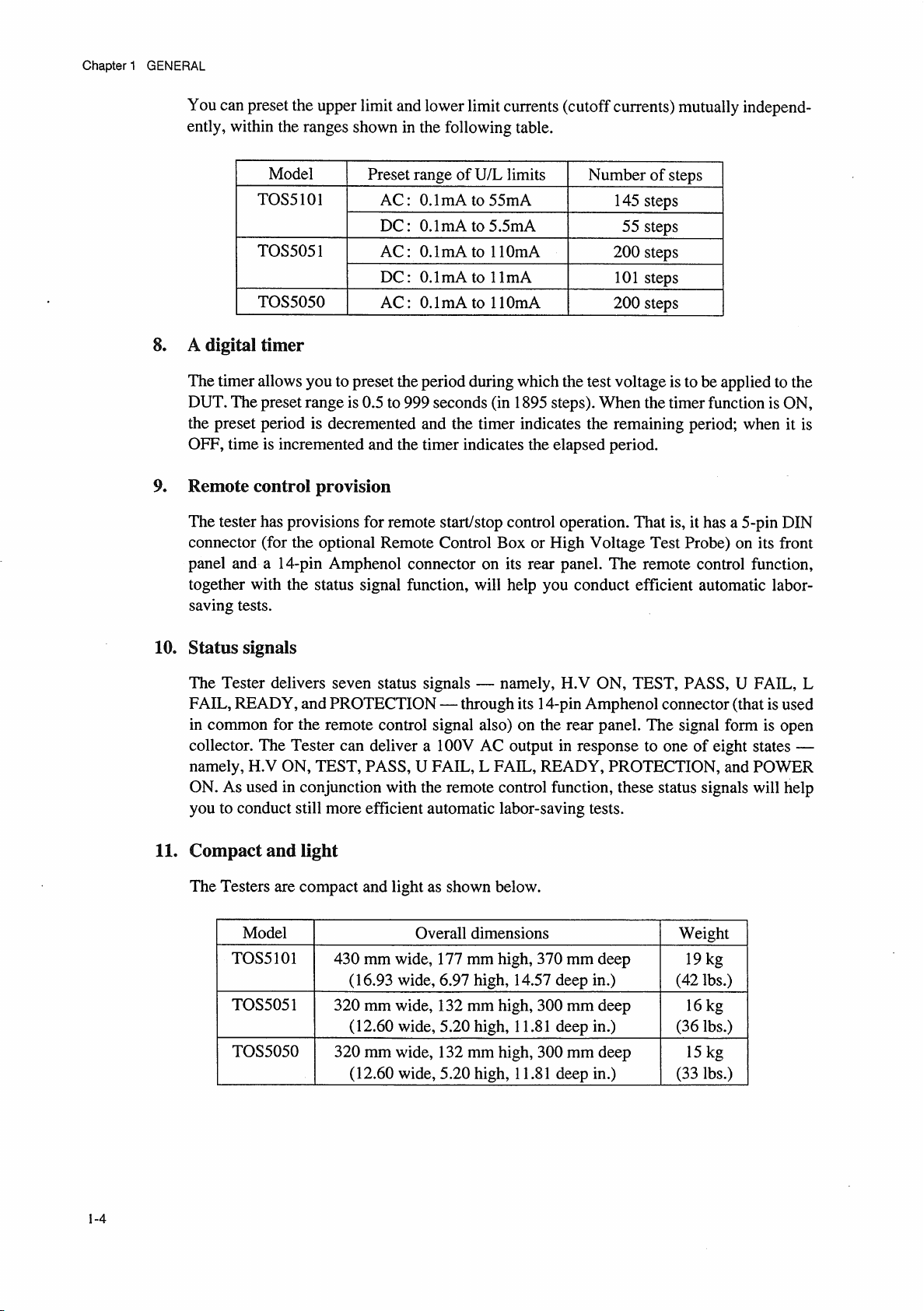
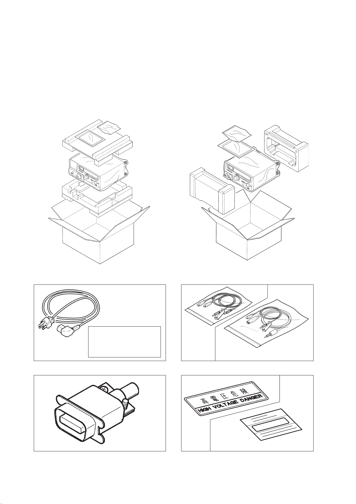
2.1 Checking for Shipping Damages and Accessories
When you receive the Tester, inspect it for any obvious damages that may have occurred during
shipment. Immediately report any damages to the carrier and your Kikusui agent.
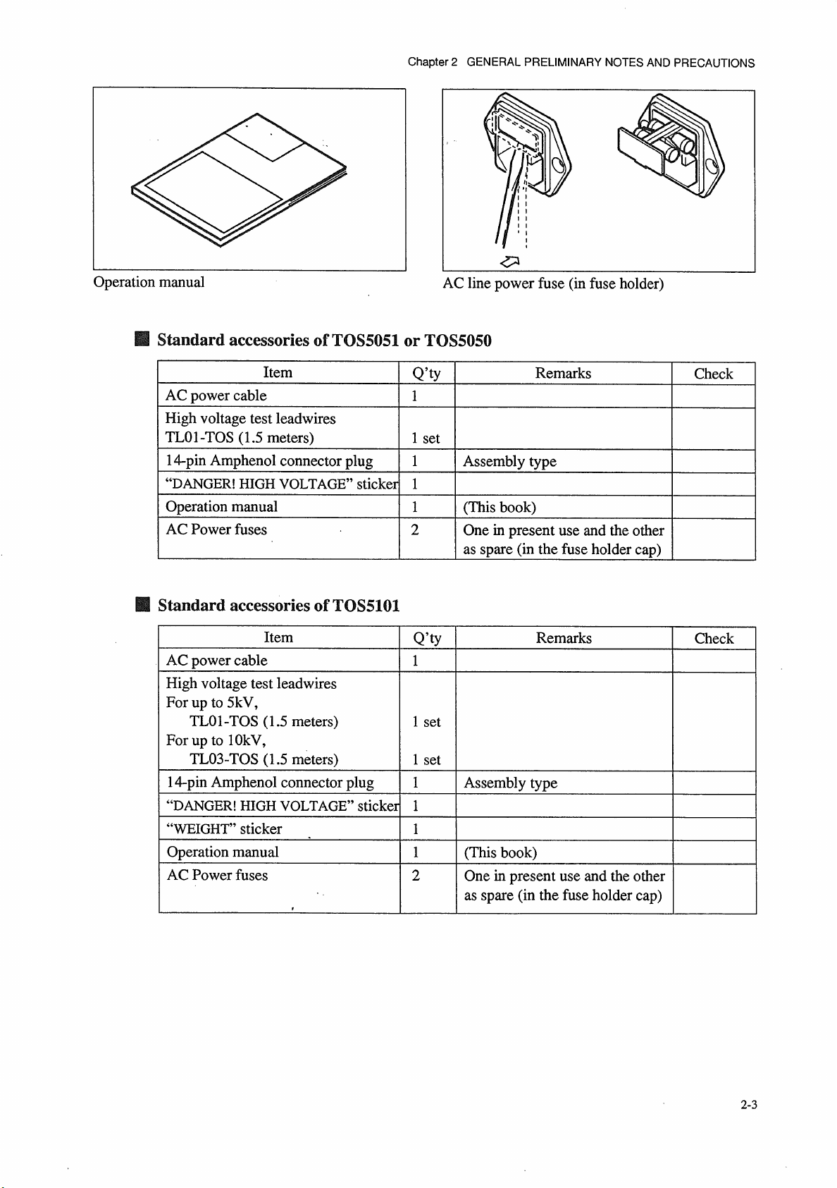
You should also find the standard accessories as shown below accompany the Tester in the same
package.
TOS5101 TOS5050/TOS5051
Do not use the AC power
cable attached to this
product for the AC power
cable of other instruments.
TL01-TOS
AC power cable HV Test Leadwires
TL03-TOS
(TOS5101 only)
○○kg
WEIGHT
(TOS5101 only)
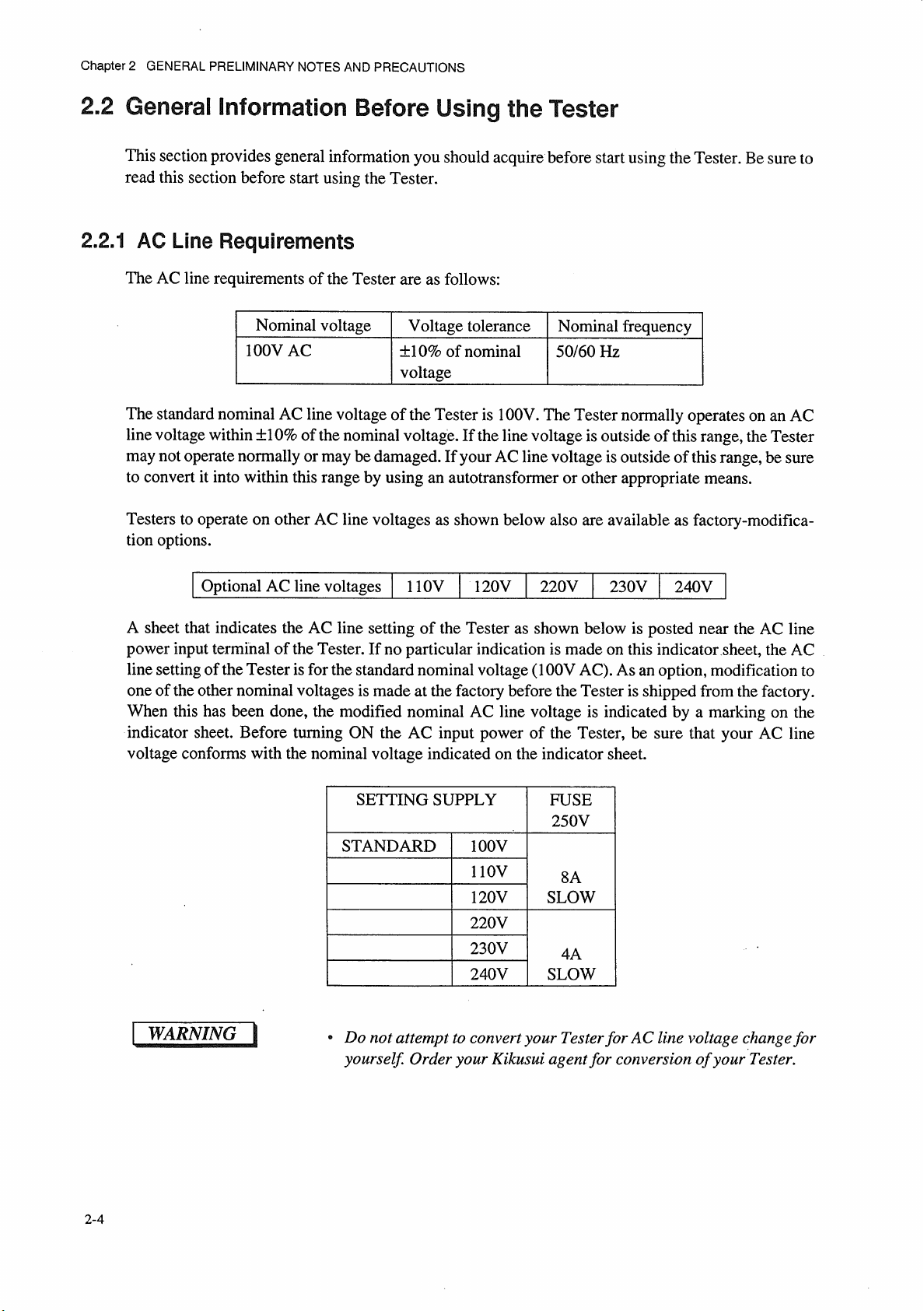
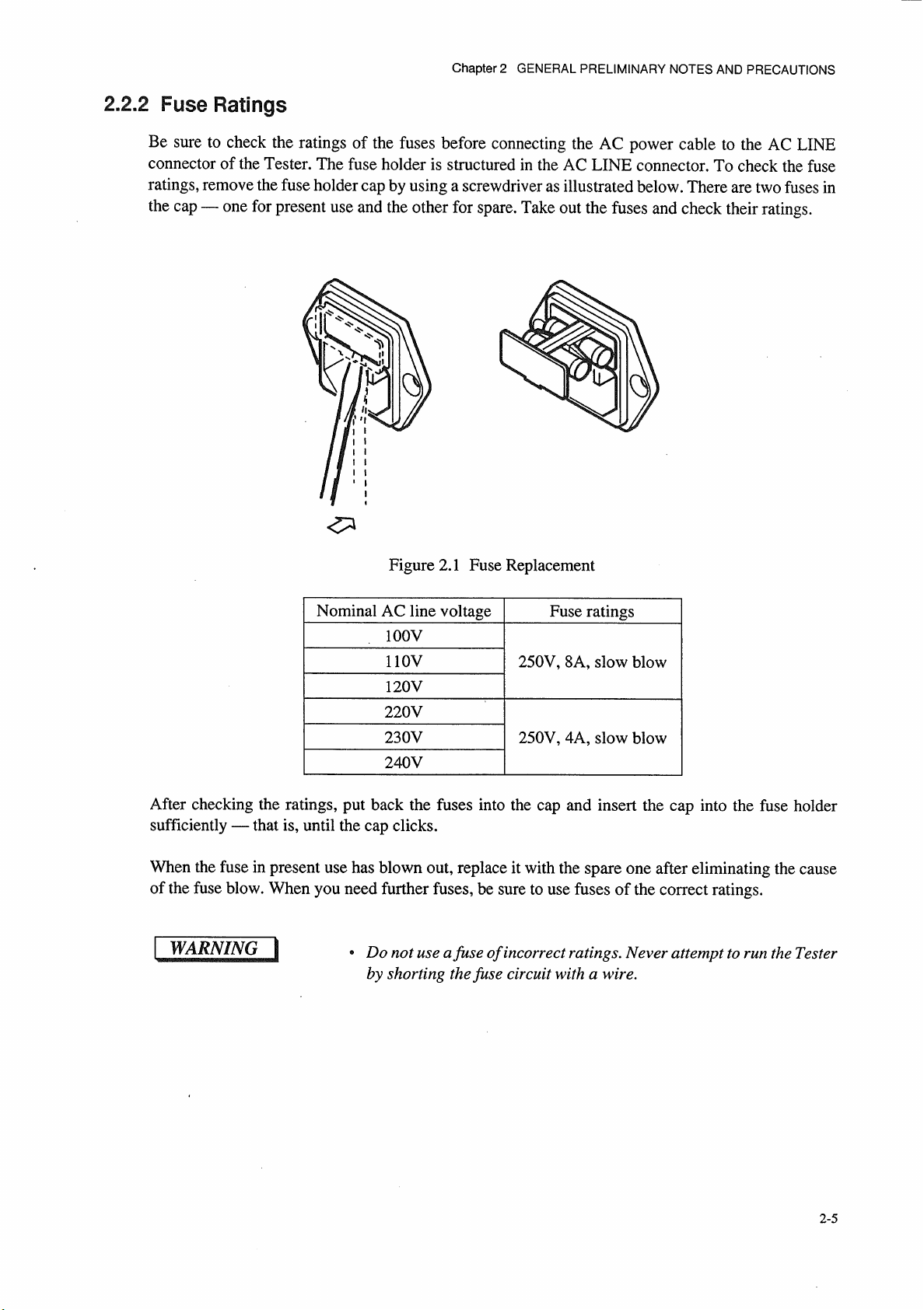
14-pin Amphenol plug (assembly type) DANGER and WEIGHT sticker
2-2
Page 23
Page 24
Page 25
Page 26

Chapter 2 GENERAL PRELIMINARY NOTES AND PRECAUTIONS
2.2.3 Environmental Conditions
Be sure to observe the following precautions when installing the tester.
■ Do not use the tester in a flammable atmosphere.
To prevent explosion or fire, do not use the tester near alcohol, thinner, or other combustible
materials, or in an atmosphere containing such vapors.
■ Avoid locations where the tester is exposed to high temperatures or direct
sunlight.
Do not locate the tester near a heater or in areas subject to drastic temperature changes.
Operating temperature range: 0 ˚C to +40 ˚C
Storage temperature range: -20 ˚C to +70 ˚C
■ Avoid humid environments.
Do not locate the tester in a high-humidity environment-near a boiler, humidifier, or water supply.
Operating humidity range: 20 % to 80 % RH
(no dew condensation permitted)
Storage humidity range: 80 % RH or less
(no dew condensation permitted)
Condensation may occur even within the operating humidity range. In that case, do not start using the
tester until the location is completely dry.
■ Do not place the tester in a corrosive atmosphere.
Do not install the tester in a corrosive atmosphere or one containing sulfuric acid mist or the like. This
may cause corrosion of various conductors and imperfect contact with connectors, leading to
malfunction and failure, or in the worst case, a fire.
■ Do not locate the tester in a dusty environment.
Dirt and dust in the tester may cause electrical shock or fire.
■ Do not use the tester where ventilation is poor.
Prepare sufficient space around the tester to allow for air flow.
■ Do not place the tester on a tilted surface or in a location subject to
vibrations.
If placed on a non-level surface or in a location subject to vibration, the tester may fall, resulting in
damage and injury.
■ Do not use the tester in locations affected by strong magnetic or electric
fields.
Operation in a location subject to magnetic or electric fields may cause the tester to malfunction,
resulting in electrical shock or fire.
2-6
Page 27

Chapter 2 GENERAL PRELIMINARY NOTES AND PRECAUTIONS
■ Do not use the tester in locations near a sensitive measuring instrument or
receiver.
Operation in a location subject, may cause such equipment may be affected by noise generated by the
tester. At a test voltage exceeding 3 kV, corona discharge may be generated to produce substantial
amounts of RF broadband emissions between grips on the test leadwire. To minimize this effect,
secure a sufficient distance between alligator clips.
In addition, keep the alligator clips and test leadwire away from the surfaces of conductors (particularly
sharp metal ends).
■ Secure adequate space around the power plug.
Do not insert the power plug to an outlet where accessibility to the plug is poor. And, do not place
objects near the outlet that would result in poor accessibility to the plug.
2-7
Page 28

Chapter 2 GENERAL PRELIMINARY NOTES AND PRECAUTIONS
2.2.4 Notes for Moving the Tester
When moving the tester to the installation site or otherwise transporting it, take the following
precautions:
■ Before moving the tester, turn off the power switch.
Transporting the tester with its POWER switch on can lead to electric shock and damage.
■ When moving the tester, Disconnect all wires from it.
Moving the tester without disconnecting the cables may result in breakage of the wire or injury due to
the tester tipping over.
■ For transportation, use the special packing material for the tester.
Transport the tester in its original package to prevent vibration and falls, which may damage the
tester. If you require packing material, contact Kikusui distributor/agent.
■ Have two or more people move the tester.
The TOS5101 weighs approximately 21 kg. Two persons are required to carry the TOS5101.
Take extreme care when moving the TOS5101.
2-8
Page 29
Page 30
Page 31

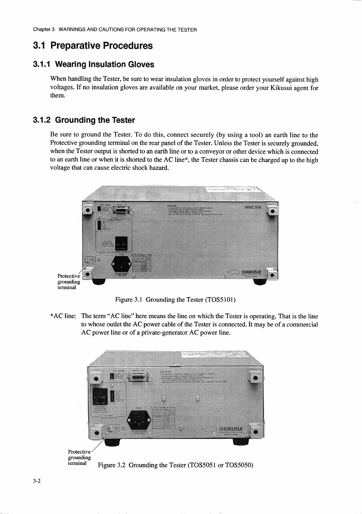
Chapter 3 WARNINGS AND CAUTIONS FOR OPERATING THE TESTER
3.2 Warnings and Cautions when Operating the Tester
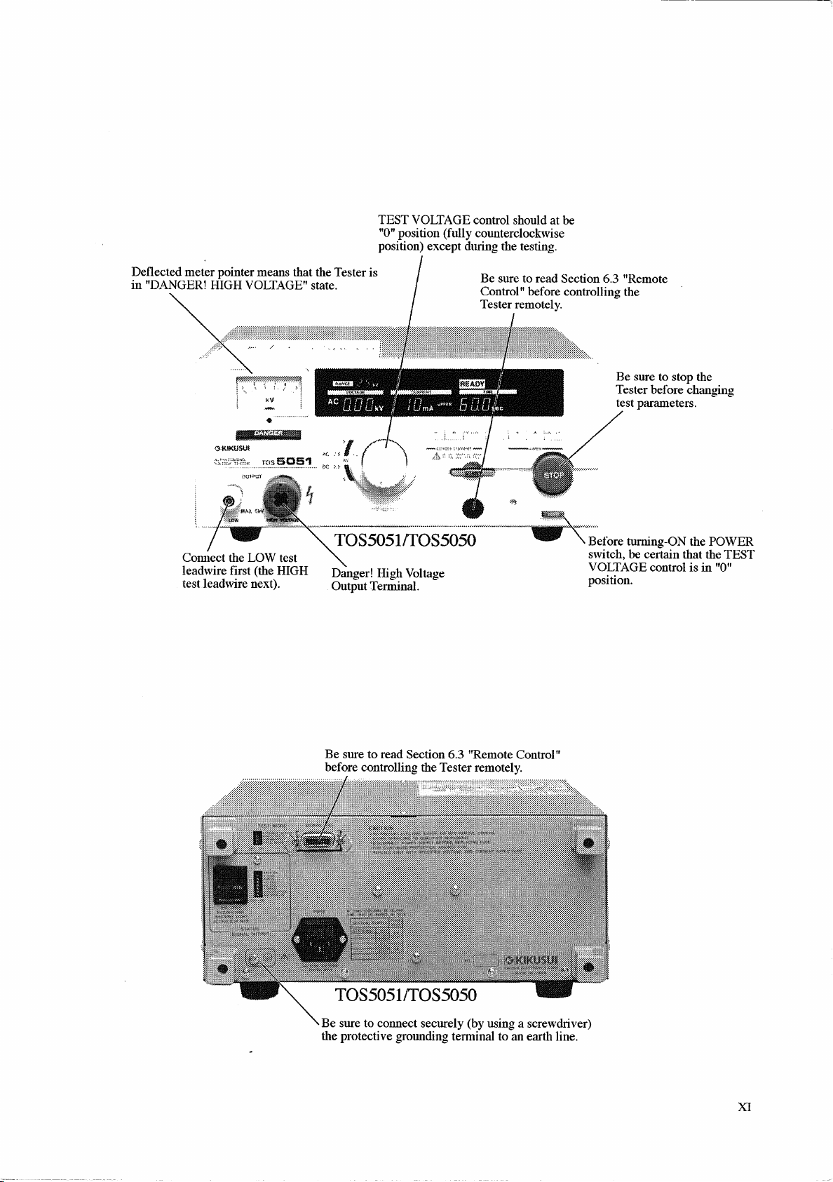
3.2.1 Connecting the LOW Test Leadwire
For the connection method of the LOW test leadwire to the LOW output terminal of the Tester, see
Figure 3.3. Each time before start using the Tester, check that the LOW test leadwire is not broken.
When connecting the Tester to a DUT (device under test), connect the LOW test leadwire first (and
the HIGH test leadwire next) and be sure that it securely connects the LOW output terminal of the
Tester to the corresponding terminal (chassis protective grounding terminal) of the DUT. If the
connection is imperfect, overall DUT can be charged up to a hazardous high voltage.
LOW output terminal
Test leadwire (black) to DUT
Install the leadwire clamp as this
Figure 3.3 Connecting the LOW Test Leadwire (TOS5101)
3.2.2 Connecting the HIGH Test Leadwire
Be sure to observe the order of leadwire connections — the LOW test leadwire first and the HIGH test
leadwire next. To connect the Tester to a DUT, proceed as follows:
Step 1
Step 2
Step 3
Step 4
Step 5
Step 6
Press the
Check that the output voltmeter reading is zero.
Check that the
Connect the HIGH test leadwire to the HIGH VOLTAGE output terminal.
Short the LOW and HIGH test leadwires, and check that no high voltage is output.
Connect the Tester to the DUT, with the LOW output leadwire first and and HIGH
output leadwire next.
STOP
switch.
DANGER
lamp is OFF.
3-3
Page 32

Page 33

Page 34

Chapter 3 WARNINGS AND CAUTIONS FOR OPERATING THE TESTER
3.3.2 Residual High Voltages
Warning for Residual High Voltages
When you do a test with the DC output, the DUT, test leadwires, probes, and output terminals and
their vicinities are charged up to high voltages. Even after you turned off the DC output, these
voltages remain there for a period that depends on the conditions of the test. Within this period, never
touch the DUT, test leadwires, probes, or output terminals or their vicinities to avoid electric shock
hazard.
Before touching any of them, be sure of the following two matters and short the LOW and HIGH test
leadwires.
(a) The output voltmeter indicates “zero”.
(b) The DANGER lamp has gone out.
Discharge Time of Residual High Voltages
The period of time the residual high voltages take to be discharged vary depending on test conditions
— such as the properties of DUT and the test voltage delivered by Tester (Model TOS5101 or
TOS5051). When no DUT is connected, the period the Tester itself (internal capacitor of the Tester)
takes to be discharged is as follows:
Discharge time of Tester itself
Discharge time of Tester itself
Tester model
5kV 10kV
TOS5101 Approx. 22ms Approx. 24ms
TOS5051 Approx. 16ms —
(Period the Tester output terminal voltage takes to be reduced to 30V)
When a DUT whose capacitance is 0.05
µ
F is connected to the Tester, the discharge time is as follows:
Discharge time of Tester itself
Tester model
5kV 10kV
TOS5101 Approx. 140ms Approx. 170ms
TOS5051 Approx. 50ms —
(Period the Tester output terminal voltage takes to be reduced to 30V)
The Tester has an internal circuit to discharge the residual high voltage of its output circuit when its
output is turned off. Do not disconnect the DUT from the Tester when in test. If you do this, the
residual high voltage on the DUT may remain undischarged for a long period.
3-6
Page 35

Page 36

Page 37

Page 38

Page 39

Chapter 4 DESCRIPTION OF FRONT AND REAR PANEL ITEMS
Chapter 4
DESCRIPTION OF FRONT
AND REAR PANEL ITEMS
This chapter describes the items on the front and rear panels of the Tester.
Table of contents Page
4.1 Description of Front Panel Items ...................................... 4-2
4.1.1 Turning ON/OFF the AC Input Power ..................... 4-3
4.1.2 Start/Stop of Test ...................................................... 4-5
4.1.3 Test Voltage.............................................................. 4-9
4.1.4 Cutoff Currents ......................................................... 4-12
4.1.5 Test Time.................................................................. 4-15
4.1.6 Others ....................................................................... 4-17
4.2 Display Items .................................................................... 4-18
4.2.1 Test Voltage Display ................................................ 4-18
4.2.2 Readout for Cutoff Current and
Measured Current ..................................................... 4-21
4.2.3 Test Time Display .................................................... 4-23
4.2.4 READY Message ..................................................... 4-24
4.2.5 TEST Message.......................................................... 4-24
4.2.6 PASS Message.......................................................... 4-24
4.2.7 FAIL Messages......................................................... 4-24
4.2.8 PROTECTION Messages......................................... 4-25
4.2.9 Others ....................................................................... 4-25
4.3 Description of Rear Panel Items ....................................... 4-26
4-1
Page 40

Chapter 4 DESCRIPTION OF FRONT AND REAR PANEL ITEMS
4.1 Description of Front Panel Items
9 10 11 18 12 13 16 14 15
Figure 4.1 TOS5050 Front Panel
9
10
11
18
12
13
16
14
31172 45678
15
4-2
5
Figure 4.2 TOS5051 Front Panel
678
4
31172
Page 41

Chapter 4 DESCRIPTION OF FRONT AND REAR PANEL ITEMS
16
9
10 11
Figure 4.3 TOS5101 Front Panel
4.1.1 Turning ON/OFF the AC Input Power
18
5 678
12
13
4
14
15
31172
1
POWER
The
The Tester has a “resume” function. When you turn ON the
Switch
POWER
switch turns ON/OFF the AC mains power of the Tester.
POWER
switch, the Tester
automatically resumes the conditions of test (settings of cutoff current, test period, etc.) that
existed when you turned OFF the
By pressing the
POWER
switch while keeping the
POWER
switch last time.
SHIFT
key 16 depressed, you can
initialize the test conditions to the initial setup (factory default setup) as shown below. If you do
this, the data on the test conditions that existed when you turned OFF the
POWER
switch last
time is lost.
Item Initial setup data
Upper cutoff current 0.2mA
Lower cutoff current 0.1mA
Lower pass/fail judgement OFF
Test period 0.5 s
Timer function ON
Keylock function OFF
4-3
Page 42

Chapter 4 DESCRIPTION OF FRONT AND REAR PANEL ITEMS
37
3
3
5
19
0
5
Caution
• Be sure to read Chapter 3 “WARNINGS AND CAUTIONS FOR
OPERATING THE TESTER” (Page 3-1) of this manual before start
using the Tester.
• Before turning ON the
VOLTAGE
control 6 is in the fully counterclockwise position (“0”
POWER
switch, be sure that the
TEST
position).
• If you want to enter a setting value you have selected, wait approximately 0.5 seconds before turning OFF the POWER switch. If you
turn off the switch without waiting for this period, the value may not
be successfully entered.
• Normally, as you turn ON the
POWER
switch, the TESTER will
become the READY state (the READY lamp 28 will light up).
However, the lamp will not light up in the following cases:
(a) The Tester is in the PROTECTION status.
i. The interlock pins of the SIGNAL I/O connector
on the rear
panel are open.
(For detail, refer to Section 6.3.3 “Interlock Function”)
If the above is the case, eliminate the interlock signal and reset
from the PROTECTION status with the
STOP
switch
and then start operating the Tester.
ii. When in DC test (for TOS5101 and TOS5051 only), the high
voltage supply section is overheated.
If the above is the case, wait until the Tester cools off and then
reset from the PROTECTION status with the
STOP
switch
and then start operating the Tester.
(b) The lower cutoff current setting is higher than the upper cutoff
current setting and the lower pass/fail judgement function is ON.
If the above is the case, make the lower cutoff current setting
lower than the upper cutoff current or turn OFF the lower pass/
fail judgement function and then start operating the Tester.
(c) The
switch
POWER
switch is turned ON while the TEST VOLTAGE
is caught on a midway in turning from one range
position to another range position.
When in the above state, the TEST VOLTAGE RANGE message
will indicate 0 kV, both AC / DC test mode message
2
will
appear at the same time (except for TOS5050) and will blink to
show that no range selection has been successfully accomplished.
If the above is the case, turn the TEST VOLTAGE switch
accurately to a range position you may require and then start
operating the Tester.
4-4
Page 43

4.1.2 Start/Stop of Test
2
8
18
4
4
7
8
7
4
3
9
9
7
Chapter 4 DESCRIPTION OF FRONT AND REAR PANEL ITEMS
START
If you press the
READY message
display screen
If the REMOTE message
Switch
START
switch 2 when the Tester is in the READY state (state that the
2
appears), the Tester will execute the test with parameters shown on the
(Vaccum Fluorescent Display).
3
is shown, the
START
switch 2 is disabled and the remote start
control signal applied through the REMOTE CONTROL connector
SIGNAL I/O connector
If the MOMENTARY switch of TEST MODE switch
will be executed only during the period you keep depress the
3
is enabled.
3
on the rear panel is set to ON, the test
START
switch 2. For details,
refer to Section 6.5 “Settings for Special Test Modes.”
Caution
• Do not remote-control the Tester simultaneously from both
MOTE CONTROL
connector 4 and
you do this, the REMOTE message
SIGNAL I/O
3
will go out and the
connector
switch 2 will be enabled. For details, refer to Section 6.3 “Remote
Control.”
STOP
Switch
or the
RE-
3
. If
START
The
STOP
switch 3 is to stop the test and reset the Tester. As you press this switch, the Tester
will act as follows:
1.
Reset from TEST status (status that the TEST message
2
appears)
The Tester will stop the test and act as follows:
(a) Turns OFF the output with the highest priority.
(b) Brings the discharge function into effect if the test is in the DC mode.
(c)
Turns OFF the DANGER lamp 9 , provided that there is no residual test voltage in
the output circuit.
(d)
Lets the TEST message
2
disappear.
(e) Turns OFF the TEST signal and the HV ON signal fed through the SIGNAL I/O
connector
3
.
4-5
Page 44

Chapter 4 DESCRIPTION OF FRONT AND REAR PANEL ITEMS
0
0
7
1
1
7
7
2
7
7
8
8
7
2. Reset from PASS status (status that the PASS message
3
appears)
The Tester will reset from the PASS status and act as follows:
Lets the PASS message
(a)
3
disappear.
(b) Turns OFF the PASS signal fed through the SIGNAL I/O connector
3.
Reset from FAIL status (status that the FAIL message
3
appears)
The Tester will reset from the FAIL status and act as follows:
(a)
Lets the UPPER FAIL message 31 disappear.
(b)
Lets the LOWER FAIL message
3
disappear.
(c) Turns OFF the U FAIL (upper fail) signal fed through the SIGNAL I/O connector
(d) Turns OFF the L FAIL (lower fail) signal fed through the SIGNAL I/O connector
4. Reset from PROTECTION status
3
.
3
.
3
.
The Tester will reset from the PROTECTION status and act follows:
(a)
Lets the PROTECTION message
3
disappear.
(b) Turns OFF the PROTECTION signal fed through the SIGNAL I/O connector
However, the Tester will not reset from the PROTECTION status if the interlock pins of
the SIGNAL I/O connector
3
are open or if the high voltage supply section is overheated
in DC test (for TOS5101 and TOS5051 only). If this is the case, eliminate the interlock
signal (For detail refer to Section 6.3.3 “Interlock Function”) or wait until the Tester cools
off and then reset from the PROTECTION status with the
5.
Reset from READY status (status that the READY message
STOP
switch 3.
2
appears)
The Tester will reset from the READY status and act as follows:
(a)
Lets the READY message
(b) Turns OFF the READY signal fed through the SIGNAL I/O connector
2
disappear.
3
3
.
.
4-6
Page 45

Chapter 4 DESCRIPTION OF FRONT AND REAR PANEL ITEMS
8
7
9
3
8
8
8
1
2
Normally, as you release the
(status that the READY message
STOP
switch 3, the Tester will become the READY status
2
appears). In the following cases, however, the Tester will
not become the READY status.
1. The cause of PROTECTION status remaining un-eliminated
(a) The interlock pins of the SIGNAL I/O connector
3
on the rear panel are open. (For
details, refer to Section 6.3.3 “Interlock Function.”)
(b) When in DC test (for TOS5101 and TOS5051 only), the high voltage supply section is
overheated.
2. The test voltage remaining undischarged
This is such state that the DANGER lamp 9 remains lighted in spite of that the
TEST message
3. A period of approximately 0.5 seconds has elapsed after releasing the
when the DOUBLE ACTION switch of the TEST MODE switch
If the DOUBLE ACTION switch of the TEST MODE switch
will become the READY state as you release the
2
has disappeared.
STOP
STOP
3
is set for ON.
3
is set for ON, the Tester
switch 3. Then, when a period
of approximately 0.5 seconds has elapsed, the Tester will automatically reset from the
READY status. For details, refer to Section 6.5 “Settings for Special Test Modes.”
switch
4. The
Caution
STOP
switch 3 is released while the
• If the FAIL MODE switch of the
ON, resetting from the FAIL status (status that the FAIL message
3
appears) or from the PROTECTION status (status that the
PROTECTION message
switch 3 only. For details, refer to Section 6.5 “Settings for Special
Test Modes.”
START
switch 2 is pressed.
TEST MODE
3
appears) can be done with the
switch
3
is set for
STOP
4-7
Page 46

Chapter 4 DESCRIPTION OF FRONT AND REAR PANEL ITEMS
4
4
2
4
2
7
7
4
REMOTE CONTROL Connector
This connector is for remote control of start/stop of test operation from an optional device such
as Remote Control Box (RC01-TOS or RC02-TOS) or H.V Test Probe (HP01A-TOS or
HP02A-TOS).
As you connect the plug of the optional device, the remote control circuit is established and the
REMOTE message
3
appears and the local
Tester becomes the PROTECTION status (status that the PROTECTION message
appears) and the high voltage output is cut off. The STOP operation can be done either locally
from the
STOP
switch 3 on the front panel or remotely from the optional device.
START
switch 2 is disabled. In this case, the
3
As you disconnect the plug of the optional device, the REMOTE message
START
the
PROTECTION message
Caution
switch 2 is enabled. The Tester becomes the PROTECTION status (status that the
3
appears) and the high voltage output is cut off.
• For remote-control of the test start/stop operation of the Tester from
other device than one of the optional devices of the Tester, do not use
the
REMOTE CONTROL
the
SIGNAL I/O
connector
connector 4 on the front panel but use
3
on the rear panel.
• Of the optional H.V Test Probe (HP01A-TOS or HP02A-TOS), the
maximum allowable test voltage is 4 kV when in the AC test mode or
5 kV when in the DC test mode.
• Do not remote-control the Tester simultaneously from both
MOTE CONTROL
connector 4 and
you do this, the REMOTE message
START
switch 2 will be enabled.
SIGNAL I/O
3
will disappear and the
• If the Remote Control Box is with its UNCONDITIONAL STOP
function effected, the Tester will not become the PROTECTION
status when the plug of the box is connected to the
CONTROL
connected to the
connector 4. When the plug of the HV Test Probe is
REMOTE CONTROL
connector 4. the Tester
will not become the PROTECTION status because the probe is in the
state that its UNCONDITIONAL STOP function is effected.
3
disappears and
connector
REMOTE
RE-
3
. If
• Be sure to read Section 6.3 “Remote Control” before remote-controlling the Tester.
• To reset the Tester from the PROTECTION status, press the
STOP
switch 3.
4-8
Page 47

4.1.3 Test Voltage
5TEST VOLTAGE Switch
The TEST VOLTAGE switch 5 selects a test voltage range and test mode for AC or DC
(TOS5050 has no DC test mode).
Chapter 4 DESCRIPTION OF FRONT AND REAR PANEL ITEMS
The TEST VOLTAGE switch
the READY message
(status that the TEST message
FAIL judgement (when the PASS message
5
is enabled when the Tester is in the READY status (status that
28
appears); it is disabled when the Tester is in the TEST-ON status
29
appears) or when the Tester is delivering the result of PASS/
30
or the FAIL message
31
appears).
The Tester takes approximately 0.5 seconds to respond to a range change by this switch. The test
cannot be started during this period. (If the READY message
28
has been displayed, it
disappears for this period.)
When the range you selected is entered, the TEST VOLTAGE RANGE message
AC / DC test mode message
message can be reset from blinking by pressing the
pressing the
START
switch 2.
blinks to indicated that the entry has been completed. The
20
STOP
switch 3 or by starting the test by
19
or
Model Selectable ranges and mode
TOS5101 10kV AC 5kV AC 10kV DC 5kV DC
TOS5051 5kV AC 2.5kV AC 5kV DC 2.5kV DC
TOS5050 5kV AC 2.5kV AC - -
Caution
• Before turning the
TEST VOLTAGE
TEST VOLTAGE
switch 5, be sure that the
control 6 is in the fully counterclockwise posi-
tion (“0” position).
•
During the TEST-ON period (period that the TEST message
appears), the
TEST VOLTAGE
switch 5 is disabled. During this
period, it is possible that the actual position of the switch does not
conform with the TEST VOLTAGE RANGE message
AC / DC test mode message
. When the test period has elapsed,
20
19
or the
the switch is enabled and the selected test voltage range and AC/DC
mode (mode selection is for TOS5101 and TOS5051 only) are effected. Do not operate the Tester in this manner — that is, do not
change the
TEST VOLTAGE
switch 5 during the TEST-ON pe-
riod.
• Do not let the
TEST VOLTAGE
switch 5 caught on a midway in
turning it from one range position to another range position. If you
turn ON the POWER switch while the
TEST VOLTAGE
switch 5 is
caught on a midway, the TEST VOLTAGE RANGE message
indicate 0 kV, both AC / DC test mode messages
will appear at
20
the same time (except for TOS5050) and will blink to show that no
range selection has been successfully accomplished. When changing
the
TEST VOLTAGE
switch 5, turn it securely to the required
range position.
19
29
will
4-9
Page 48

Chapter 4 DESCRIPTION OF FRONT AND REAR PANEL ITEMS
6
5
7
8
8
TEST VOLTAGE Control
This control is to adjust the test voltage. As you turn the control clockwise from the “0” position,
the test voltage increases. The “MAX” position is for the highest test voltage corresponding to
the voltage range value selected by the TEST VOLTAGE switch
For the AC/DC models (TOS5101 and TOS5051), the control is for both AC and DC test modes.
Model Selectable ranges and mode
TOS5101 0 to 10kV AC or more 0 to 5kV AC or more
0 to 10kV DC or more 0 to 5kV DC or more
TOS5051 0 to 5kV AC or more 0 to 2.5kV AC or more
0 to 5kV DC or more 0 to 2.5kV DC or more
TOS5050 0 to 5kV AC or more 0 to 2.5kV AC or more
.
Caution
• Be sure to keep the
TEST VOLTAGE
control 6 in the fully
counterclockwise position (“0” position) whenever no test is done.
• When the
TEST VOLTAGE
control 6 is set in the fully clockwise
position (“MAX” position) in the no load state, the output voltage in
the DC mode may be higher than the test voltage range value you
selected with the
TEST VOLTAGE
switch 5. In the AC mode, the
output voltage may be higher still depending on change of the AC line
voltage. Although higher voltages may be available, be sure to
operate the Tester with voltages lower than the corresponding range
value.
HIGH VOLTAGE Terminal
This terminal is for the high line of the Tester output. The output voltage is delivered between
this terminal and the LOW terminal
. For the AC/DC models (TOS5101 and TOS5051), this
terminal serves in common for both AC and DC modes of test operation.
WARNING
• Never touch the
HIGH VOLTAGE
terminal 7 when in the
TEST-ON status (status that the DANGER lamp 9 lights or the
TEST message 29 appears).
LOW Terminal
This terminal is for the low line of the Tester output. This terminal is directly connected to the
Tester chassis.
4-10
Page 49

Chapter 4 DESCRIPTION OF FRONT AND REAR PANEL ITEMS
9
DANGER Lamp
This red lamp illuminates to indicate that the test voltage is being delivered. It remains
illuminating so far as there remains the test voltage in the output circuit.
WARNING
• When the DANGER lamp 9 is illuminating, never touch the
VOLTAGE
terminal 7, test leadwires, DUT, or other charged
objects.
10
Analog Voltmeter
The VOLTAGE display (analog voltmeter)
10
indicates directly the output terminal voltage. Of
the AC/DC models (TOS5101 and TOS5051), the voltmeter serves in common for both AC and
DC.
Model Measuring Range
TOS5101 0 to 10kV AC 0 to 10kV DC
TOS5051 0 to 5kV AC 0 to 5kV DC
TOS5050 0 to 5kV AC —
11
Zero Adjustment of Analog Voltmeter
This is for mechanical zero adjustment of the analog voltmeter. Before making zero adjustment,
be sure that the POWER switch is OFF.
HIGH
4-11
Page 50

Chapter 4 DESCRIPTION OF FRONT AND REAR PANEL ITEMS
12
8
3
9
0
1
2
2
8
4.1.4 Cutoff Currents
Caution
• Test time and pause period are limited by setting upper cutoff current.
"ON
…
" of the front panel character shows a maximum test time and
"OFF
…
" shows a minimum pause period. For details, refer to
chapter 9 "Specifications" (Pages 9-2, 9-3, 9-9 , 9-10 and 9-11).
Keys
The
keys 12 are for increment/decrement of cutoff currents (reference currents for pass/
fail judgement). The keys are enabled when the Tester is in the READY status (status that the
READY message
2
appears) and the KEYLOCK message
when in the TEST-ON status (status that the TEST message
is delivering the result of PASS/FAIL judgement (when the PASS message
FAIL message
3
appears).
3
has disappeared. It is disabled
2
appears) or when the Tester
3
or the
There are two cutoff currents, namely, UPPER cutoff current and LOWER cutoff current. You
can select either cutoff current with the
cutoff current with the
If you press the
or
keys 12.
key alone, the rate of increment/decrement is the basic resolution
UP/LOW
shown below. If you press it together with the
key 13 and increment/decrement the selected
SHIFT
key 16, the rate of increment/decrement
is ten times of the basic resolution. If you keep them pressed, increment/decrement repeats
automatically.
1.
key
This key increments the cutoff current setting. The set value is shown on the CURRENT
display (digital ammeter)
2.
key
2
.
This key decrements the cutoff current setting. The set value is shown on the CURRENT
display (digital ammeter)
Caution
• The UPPER and LOWER cutoff currents can be set mutually inde-
2
.
pendently and therefore it is possible that the latter is set at a value
higher than the former. If this is the case and the pass/fail judgement
function for the LOWER cutoff current is ON, however, the mA
display (unit of current measure) blinks and the READY message
2
disappears to indicate that the test in this condition cannot be
done. The READY status resumes if the LOWER cutoff current is set
at a value lower than the UPPER cutoff current or if the pass/fail
judgement function for the LOWER cutoff current is turned OFF.
4-12
Page 51

Chapter 4 DESCRIPTION OF FRONT AND REAR PANEL ITEMS
UPPER/LOWER cutoff
current range
Basic resolution Display format
0.1 to 9.9mA 0.1mA □.□mA
10 to 110mA 1mA □□□mA
Model
AC mode of test
Upper cutoff current range Lower cutoff current range
TOS5101 0.1 to 55mA 0.1 to 55mA, OFF
TOS5051 0.1 to 110mA 0.1 to 110mA, OFF
TOS5050 0.1 to 110mA 0.1 to 110mA,OFF
Model
DC mode of test
Upper cutoff current range Lower cutoff current range
TOS5101 0.1 to 5.5mA 0.1 to 5.5mA, OFF
TOS5051 0.1 to 11mA 0.1 to 11mA, OFF
TOS5050 — —
For the AC/DC models (TOS5101 and TOS5051), the upper and
lower cutoff currents can be set for AC and DC modes of tests. The
settings of cutoff currents for the AC mode and DC mode, however,
are mutually independent.
4-13
Page 52

Chapter 4 DESCRIPTION OF FRONT AND REAR PANEL ITEMS
13
8
3
9
0
1
3
4
3
2
4
2
5
UP/LOW
key
The key selects the upper or lower cutoff current. If you press the key while keeping the
key 16 pressed, the lower pass/fail judgement function is turned ON or OFF.
The
UP/LOW
READY message
when in the TEST-ON status (status that the TEST message
delivering the result of judgement (when the PASS message
key is enabled when the Tester is in the READY status (status that the
2
appears) and the KEYLOCK message
3
has disappeared. It is disabled
2
appears) or when the Tester is
3
or the FAIL message
appears).
1. When
UP/LOW
Each time as you press the
the UPPER message
The UPPER message
is displayed on the CURRENT readout
key alone is pressed
UP/LOW
2
or the LOWER message
2
means that the upper cutoff current has been selected, the value
key, the upper or lower cutoff current is selected and
2
appears.
2
, and you can adjust the value with the
keys 12.
The LOWER message
is displayed on the CURRENT readout
2
means that the lower cutoff current has been selected, the value
2
, and you can adjust the value with the
keys 12.
SHIFT
3
For the AC/DC models (TOS5101 and TOS5051), the upper and lower cutoff currents for
both AC and DC modes of tests can be selected with this key. The settings of cutoff
currents for the AC mode and DC mode, however, are mutually independent.
2. When
UP/LOW
Each time as you press the
key is pressed while keeping
UP/LOW
key, the LOWER ON message
SHIFT
key 16 pressed
2
disappears indicating that the lower pass/fail judgement function has been brought into or
out of effect.
For the AC/DC models (TOS5101 and TOS5051), the lower pass/fail judgement function
is turned ON of OFF with the
UP/LOW
key. This test condition is applied to both AC and
DC modes of tests — that is, the setting for one mode applies automatically to the other
mode also.
appears or
4-14
Page 53

4.1.5 Test Time
14
8
3
9
0
1
6
6
Keys
Chapter 4 DESCRIPTION OF FRONT AND REAR PANEL ITEMS
The
when the Tester is in the READY status (status that the READY message
KEYLOCK message
(status that the TEST message
FAIL judgement (when the PASS message
If you press the
shown below. If you press it while keeping the
keys 14 are for increment/decrement of test period of time. The keys are enabled
2
appears) and the
3
has disappeared. They are disabled when in the TEST-ON status
2
appears) or when the Tester is delivering the result of PASS/
or
3
or the FAIL message
key alone, the rate of increment/decrement is the basic resolution
SHIFT
key 16 pressed, the rate of increment/
3
appears).
decrement is ten times of the basic resolution. If you keep them pressed, increment/decrement
repeats automatically.
1.
2.
key
This key increments the test period. The set value is shown on the TIME display
key
This key decrements the test period. The set value is shown on the TIME display
2
.
2
.
Test period setting range Basic resolution Display format
0.5 to 99.9 s., OFF 0.1 s. □□.□s
100 to 999 s., OFF 1 s. □□□s
For the AC/DC models (TOS5101 and TOS5051), the test period can be set with the
keys 14 for both AC and DC modes of tests. This test condition applies in common to both AC
and DC modes of tests.
4-15
Page 54

Chapter 4 DESCRIPTION OF FRONT AND REAR PANEL ITEMS
15
7
7
6
7
6
26
6
8
3
9
0
1
3
3
12
13
14
15
ON/OFF
The
If you press it while keeping the
Key
ON/OFF
key 15 turns ON or OFF the timer function.
SHIFT
key 16 pressed, it turns ON or OFF the keylock
function.
1. When the
ON/OFF
key 15 alone is pressed
Each time as you press the key, the timer function is turned ON or OFF. If you press it
while the TIMER ON message
the TIMER ON message
the test period indicated on the TIME display
As you press the
TIMER ON message
ON/OFF
2
when the test period indicated on the TIME display
timer function ON, the TIME display
with the timer function OFF, the TIME display
The
ON/OFF
READY message
key 15 is enabled when the Tester is in the READY status (status that the
2
appears) and the KEYLOCK message
2
has disappeared, the timer function is turned ON and
2
appears. The test done under this condition terminates when
2
has elapsed.
key 15 again, the timer function is turned OFF and the
disappears. If in this status, the test does not terminates even
2
has elapsed. When in a test with the
indicates the remaining period; when in a test
2
indicates the elapsed period.
3
has disappeared. It is
disabled when the Tester is in the TEST-ON status (status that the TEST message
appears) or when the Tester is delivering the result of PASS/FAIL judgement (when the
PASS message
3
or the FAIL message
3
appears).
2
For the AC/DC models (TOS5101 and TOS5051), the timer function can be turned ON or
OFF with the
ON/OFF
key 15 for both AC and DC modes of tests. This test condition
applies in common to both AC and DC modes of tests.
2. When
If you press the
ON/OFF
key 15 is pressed while
ON/OFF
key 15 while keeping the
mentioned keys are locked and the KEYLOCK message
SHIFT
key 16 is kept pressed
SHIFT
key 16 pressed, the below-
3
appears or they are unlocked
and the message disappears. If you press them again, the below-mentioned keys are
unlocked and the KEYLOCK message
3
disappears.
When in the keylock function is ON, the following keys are locked.
(a)
(b)
(c)
(d)
keys
UP/LOW
keys
ON/OFF
key
key
4-16
Page 55

Chapter 4 DESCRIPTION OF FRONT AND REAR PANEL ITEMS
16
12
12
17
17
Therefore, the following conditions of test can be protected against inadvertent or unauthorized alterations.
(a) Upper cutoff current
(b) Lower cutoff current
(c) ON/OFF of lower pass/fail judgement function
(d) Test time
(e) ON/OFF of timer function
4.1.6 Others
SHIFT
1. If you press the
2. If you press the
3. If you press the
The
ON/OFF
key 15 is enabled regardless of the statuses of the Tester.
For the AC/DC models (TOS5101 and TOS5051), the keylock function applies in common
to both AC and DC modes of tests.
Key
POWER
switch 1 while keeping the
SHIFT
key 16 pressed, the
conditions of test are initialized.
key 12 while keeping the
SHIFT
cutoff current is incremented at a rate of ten times of that when you press the
key 16 pressed, the upper or lower
key
alone.
key 12 while keeping the
cutoff current is decremented at a rate of ten times of that when you press the
SHIFT
key 16 pressed, the upper or lower
key
alone.
4. If you press the
UP/LOW
key 13 while keeping the
SHIFT
key 16 pressed, the lower
pass/fail judgement function is turned ON or OFF.
5. If you press the
key 14 while keeping the
SHIFT
incremented at a rate of ten times of that when you press the
6. If you press the
key 14 while keeping the
SHIFT
decremented at a rate of ten times of that when you press the
7. If you press the
ON/OFF
key 15 while keeping the
key 16 pressed, the test period is
key 14 alone.
key 16 pressed, the test period is
key 14 alone.
SHIFT
key 16 pressed, the keylock
function is turned ON or OFF.
BUZZER Control
The BUZZER control
is to adjust the loudness of the buzzer that annunciates the results of
pass/fail judgements. FAIL annunciations are louder than PASS annunciations. The factory
default setting of this control is for the maximum loudness.
4-17
Page 56

Chapter 4 DESCRIPTION OF FRONT AND REAR PANEL ITEMS
18
19
5
5
9
19
0
5
19
4.2 Display Items
3219 28 29 30 31
RANGE
VOLTAGE
kV
AC
DC
20 21 22 23 25
Figure 4.4 Display
Vaccum Fluorescent Display
The vaccum fluorescent display indicats the test conditions, test results, and other items as
described in this section.
kV
4.2.1 Test Voltage Display
TEST VOLTAGE RANGE Message
This message, which is a 7-segment 2-digit message, indicates the test voltage range selected
with the TEST VOLTAGE switch
PROTECTION
CURRENT TIME
LOWER ON
UPPER
LOWER
mA
24
. The selectable test voltage ranges are as follows:
READY
TEST
TIMER ON
s
26 27 34 33
PASS
UPPER LOWER
FAIL
KEYLOCK
REMOTE
Model Test voltage range
TOS5101 10kV 5kV
TOS5051 5kV 2.5kV
TOS5050 5kV 2.5kV
Caution
• As you change test voltage ranges with the
, the TEST VOLTAGE RANGE message 19 blinks to indicate that
the ranges have been changed. Blinking stops as you press the
STOP
switch 2.
• During the TEST-0N period (period that the TEST message
appears), the
period, it is possible that the actual position of the switch does not
conform with the TEST VOLTAGE RANGE message
AC / DC test mode message
• Do not let the
turning it from one range position to another range position. If you
turn ON the
is caught on a midway, the TEST VOLTAGE RANGE message
TEST VOLTAGE
switch 3 or as you start the test by pressing the
TEST VOLTAGE
TEST VOLTAGE
POWER
switch 1 while the
switch 5 is disabled. During this
.
2
switch 5 caught on a midway in
TEST VOLTAGE
switch
START
2
or the
switch
4-18
Page 57

Chapter 4 DESCRIPTION OF FRONT AND REAR PANEL ITEMS
0
8
0
5
0
9
19
0
5
19
0
8
8
will indicate 0 kV, both AC / DC test mode messages
appear at the same time (except for TOS5050) and will blink to show
that no range selection has been successfully accomplished. When
this has occurred, turn the
TEST VOLTAGE
switch 5 accurately to
a range position. As you do so, the Tester will become the READY
2
appears). When in this
STOP
switch 3 or as you
switch 2.
AC/DC Test Mode Message
2
status (status that the READY message
status, blinking stops as you press the
start the test by pressing the
START
This message indicates whether the AC or DC test mode has been selected with the TEST
VOLTAGE switch
. The selectable modes are as follows:
Model Test Mode
TOS5101 AC DC
TOS5051 AC DC
TOS5050 AC —
Caution
• The TOS5050 is for the AC test mode only. It has no DC test mode
message
2
.
2
will
• As you change the modes with the
TEST VOLTAGE
switch 5, the
message blinks to indicate that the modes have been changed. Blinking stops as you press the
by pressing the
START
STOP
switch 2.
switch 3 or as you start the test
• During the TEST-ON period (period that the TEST message
appears), the
TEST VOLTAGE
switch 5 is disabled. During this
period, it is possible that the actual position of the switch does not
conform with the TEST VOLTAGE RANGE message
AC / DC test mode message
• Do not let the
TEST VOLTAGE
2
.
switch 5 caught on a midway in
or the
turning it from one range position to another range position. If you
turn ON the
POWER
switch 1 while the
TEST VOLTAGE
switch
is caught on a midway, the TEST VOLTAGE RANGE message
will indicate 0 kV, both AC / DC test mode messages
2
appear at the same time (except for TOS5050) and will blink to show
that no range selection has been successfully accomplished, and the
READY message
not in the READY status. When this has occurred, turn the
VOLTAGE
switch 5 accurately to a range position. As you do so,
2
will disappear to show that the Tester is
TEST
the Tester will become the READY status (status that the
READY message
as you press the
the
START
switch 2.
2
appears). When in this status, blinking stops
STOP
switch 3 or as you start the test by pressing
2
will
4-19
Page 58

Chapter 4 DESCRIPTION OF FRONT AND REAR PANEL ITEMS
1
21
1
5
2
VOLTAGE Readout (Digital Voltmeter)
The VOLTAGE display (digital voltmeter)
indicates the output voltage with a 3-digit 7-
segment readout. It constantly monitors the output terminal voltage.
For the AC/DC models (TOS5101 and TOS5051), the digital voltmeter
2
acts either as an AC
voltmeter or a DC voltmeters in response to the AC or DC mode selected by the TEST
VOLTAGE switch
.
1. Measuring ranges and resolutions
Model Measuring Range Resolution
TOS5101 AC 10kV range 0 to 14.162kV 55.54V
AC 5kV range 0 to 7.081kV 27.77V
DC 10kV range 0 to 12.750kV 50.00V
DC 5kV range 0 to 6.375kV 25.00V
TOS5051 AC 5kV range 0 to 7.081kV 27.77V
AC 2.5kV range 0 to 3.540kV 13.88V
DC 5kV range 0 to 6.375kV 25.00V
DC 2.5kV range 0 to 3.186kV 12.50V
TOS5050 AC 5kV range 0 to 7.081kV 27.77V
AC 2.5kV range 0 to 3.540kV 13.88V
2. Display formats
Voltage range Display format
0.00 to 9.99kV □.□□kV
9.99 to kV □□.□kV
Caution
• Due to the measuring resolutions, the readout may not be “0.00 kV”
when the output terminal voltage is zero volts.
4-20
Page 59

Chapter 4 DESCRIPTION OF FRONT AND REAR PANEL ITEMS
2
9
2
8
3
3
4
8
3
8
4.2.2 Readout for Cutoff Current and Measured Current
2
CURRENT Readout (Digital Ammeter)
When the Tester is in the TEST-ON status (status that the TEST message
CURRENT readout
2
indicates the measured output current; when the Tester is in other status
2
appears), the
than the TEST-ON status, it indicates the preset upper or lower cutoff current. It is a 3-digit 7segment readout.
Display change between upper and lower cutoff current settings can be done with the
key 13 when the Tester is in the READY status (status that the READY message
and the KEYLOCK message
3
has disappeared. The UPPER message
2
Tester is in the status for setting the upper cutoff current; the LOWER message
UP/LOW
2
appears)
means that the
2
means that
the Tester is in the status for setting the lower cutoff current.
You can increment/decrement the upper or lower cutoff current with the
the Tester is in the READY status (status that the READY message
KEYLOCK message
3
has disappeared. (If you press the
SHIFT
key 16 at the same time,
keys 12 when
2
appears) and the
the increment/decrement rate is multiplied by 10.)
If the lower cutoff current is higher than the upper cutoff current and the lower pass/fail
judgement function is ON, the mA display (unit of measure) blink and the READY message
2
disappears to alert you to that the setting is illogical and the test cannot be done. When the
lower cutoff current has become lower than the higher cutoff current or when the lower pass/fail
judgement function is turned OFF, the mA display automatically stops blinking and the Tester
resumes the READY status.
Of the AC/DC models (TOS5101 and TOS5051), the upper cutoff currents can be preset
mutually independently for AC test mode and DC test mode, and the lower cutoff currents also
can be preset mutually independently for AC test mode and DC test mode.
1. Displayed items
When in READY status When in TEST-0N status
When UPPER is ON When LOWER is ON
Upper cutoff current Lower cutoff current Measured current
2. Setting ranges
Model
AC mode of test
Upper cutoff current range Lower cutoff current range
TOS5101 0.1 to 55mA 0.1 to 55mA, OFF
TOS5051 0.1 to 110mA 0.1 to 110mA, OFF
TOS5050 0.1 to 110mA 0.1 to 110mA, OFF
Model
DC mode of test
pper cutoff current range Lower cutoff current range
TOS5101 0.1 to 5.5mA 0.1 to 5.5mA, OFF
TOS5051 0.1 to 11mA 0.1 to 11mA, OFF
TOS5050 — —
4-21
Page 60

Chapter 4 DESCRIPTION OF FRONT AND REAR PANEL ITEMS
3
2
8
3
9
3
4
2
4
2
8
3
9
3
4
2
5
8
3
3. Setting resolutions and display formats
UPPER/LOWER cutoff
current range
Basic resolution Display format
0.1 to 9.9mA 0.1mA □.□
10 to 110mA 1mA □□□
2
UPPER Message
This message means that the value shown on the CURRENT readout
2
is of the upper cutoff
current. Switchover between the upper and lower cutoff currents can be done with the
key 13 when the Tester is in the READY status (status that the READY message
and the KEYLOCK message
When in the TEST-ON status (status that the TEST message
message
2
and LOWER message
3
has disappeared.
2
disappear and the CURRENT readout
2
appears), both UPPER r
measured output current.
2
LOWER Message
This message means that the value shown on the CURRENT readout
2
is of the lower cutoff
current. Switchover between the upper and lower cutoff currents can be done with the
key 13 when the Tester is in the READY status (status that the READY message
and the KEYLOCK message
3
has disappeared.
UP/LOW
2
appears)
2
indicates the
UP/LOW
2
appears)
When in the TEST-ON status (status that the TEST message
message
2
and LOWER message
2
disappear and the CURRENT readout
2
appears), both UPPER i
2
indicates the
measured output current.
2
LOWER ON Message
This message means that the lower pass/fail judgement function is ON. When the function is
ON, the message appears; when it is OFF, the message disappears.
The function can be turned ON or OFF by pressing the
SHIFT
appears) and the KEYLOCK message
key 16 when the Tester is in the READY status (status that the READY message
3
has disappeared. Even when the lower pass/fail is
UP/LOW
key 13 together with the
turned OFF and the LOWER ON message has disappeared, display and adjustment of the
preset cutoff current can be done.
For the AC/DC models (TOS5101 and TOS5051), this test condition setting is applied in
common to both AC and DC modes of tests.
2
4-22
Page 61

4.2.3 Test Time Display
6
9
6
8
3
7
7
7
7
7
6
6
ON/OFF
8
3
2
TIME Display
Chapter 4 DESCRIPTION OF FRONT AND REAR PANEL ITEMS
When in the TEST-ON status (status that the TEST message
2
indicates the remaining or elapsed test time on a 3-digit 7-segment readout.
The preset test period can be incremented/decremented with the
is in the READY status (status that the READY message
message
3
has disappeared. If you press the
keys together with the
or
2
appears), the TIME display
keys 14 when the Tester
2
appears) and the KEYLOCK
SHIFT
key 16,
the increment/decrement rate is multiplied by a factor of 10.
If the timer function is ON (status that the TIMER ON message
2
appears), the displayed
period decreases as test time elapses and the test terminates when the preset test period has
elapsed. If the timer function is OFF (status that the TIMER ON message
2
has disappeared),
the displayed period starts by zero and increases as test time elapses—the test does not
terminates even when the preset test period has elapsed.
For the AC/DC models (TOS5101 and TOS5051), the preset test period applies in common to
both AC and DC modes of tests.
1. Displayed items
Desplayed items
When in READY status When in TEST-ON status
TIMER ON appears TIMER ON disappears
Period displayed Remaining period Elapsed period
2. Setting ranges, resolutions, and display formats
Setting range Basic resolution Display format
0.5 to 99.9 s, OFF 0.1 s □□.□
100 to 999 s, OFF 1 s □□□
2
TIMER ON Message
This message appears to mean that the TIMER function is ON. If the Tester is in the TIMER-ON
status (status that the TIMER ON message
2
appears), the test terminates when the preset test
time has elapsed. If Tester is in the TIMER-OFF status (status that the TIMER ON message
has disappeared), the test does not terminates even when the preset test period has elapsed.
When in the TIMER-ON status, the TIME display
in the TIMER-OFF status, the TIME display
The TIMER function can be turned on or off with the
READY status (status that the READY message
2
indicates the remaining test period; when
2
indicates the elapsed test period.
key 15 when the Tester is in the
2
appears) and the KEYLOCK message
has disappeared.
For the AC/DC models (TOS5101 and TOS5051), the same test condition applies in common to
both AC and DC modes of tests.
2
3
4-23
Page 62

Chapter 4 DESCRIPTION OF FRONT AND REAR PANEL ITEMS
8
18
9
0
8
1
1
4.2.4 READY Message
2
READY Message
This message means that the Tester is ready to start the test operation. As you press the
START
switch 2 while this message is displayed, the Tester will start the test operation with
the test parameters displayed on the display screen
4.2.5 TEST Message
2
TEST Message
This message (red) means that the Tester is in the TEST-ON status (status that the Tester is
executing the test by delivering the test voltage). When you want to reset from this status, press
the
STOP
switch 3.
4.2.6 PASS Message
3
PASS Message
.
This message (green) appears when the result of pass/fail judgement is PASS. (It appears when
the result is PASS within the test period. So it does not appear if the TIMER function is OFF or
the test is aborted.)
Normally, it appears only for a short period — approximately 0.2 seconds. If you set to ON the
PASS HOLD switch of TEST MODE switch
To reset the message from the held state, press the
4.2.7 FAIL Messages
3
UPPER FAIL message
This message (yellow) appears when the result of upper pass/fail judgement is FAIL, indicating
that the leak current that flowed through the DUT was larger than the preset high limit (upper
cutoff current). To reset the message, press the
3
LOWER FAIL message
This message (yellow) appears when the result of lower pass/fail judgement is FAIL, indicating
that the leak current that flowed through the DUT was less than the preset low limit (lower cutoff
current). To reset the message, press the
STOP
3
, the message is held displayed continuously.
STOP
STOP
switch 3.
switch 3.
switch 3.
4-24
Page 63

4.2.8 PROTECTION Message
2
3
4
7
7
3
12
13
14
15
15
4
4
7
3
PROTECTION Message
This message (yellow) appears when the Tester has tripped into the PROTECTION status and
its output voltage is cut off, due to any of the causes as mentioned below. To reset the Tester
from the PROTECTION status, eliminate the cause of the trip and then press the
.
Chapter 4 DESCRIPTION OF FRONT AND REAR PANEL ITEMS
STOP
switch
1. The plug is connected to or disconnected from the REMOTE CONTROL connector
2. The status of the REMOTE ENABLE signal input pins of the SIGNAL I/O connector
3. The INTERLOCK signal input pins of the SIGNAL I/O connector
4. The high voltage supply circuit of the DC test section (TOS5101 and TOS5051 only) is
4.2.9 Others
3
KEYLOCK Message
This message appears when the keylock function is ON; it disappears when the function is OFF.
The keylock function disables the following keys:
1.
2.
3.
4.
has changed.
overheated.
keys
UP/LOW
keys
ON/OFF
key
key
3
are make open.
.
3
Thus, the settings of the following test conditions are protected.
1. Upper cutoff current
2. Lower cutoff current
3. ON/OFF of lower pass/fail judgement
4. Test time
5. ON/OFF of timer function
The keylock function can be turned ON or OFF at any time, by pressing the
while keeping the
3
REMOTE Message
SHIFT
key 16 key pressed.
ON/OFF
This message appears to indicate that the Tester is being remote-controlled via the REMOTE
CONTROL connector
the
START
switch 2 is disabled. For details. refer to Section 6.3 “Remote Control.”
or the SIGNAL I/O connector
3
. When this message has appeared,
key
4-25
Page 64

Chapter 4 DESCRIPTION OF FRONT AND REAR PANEL ITEMS
5
5
4.3 Description of Rear Panel Items
39
3840 37
35 36
Figure 4.5 TOS5050/TOS5051 Rear Panel
39
40
38
37
35
36
Figure 4.6 TOS 5101 Rear Panel
3
Protective Grounding Terminal
This terminal is for grounding the Tester to an earth ground.
WARNING
• Be sure to connect securely (by using a screwdriver) an earth ground
line to the Protective grounding terminal
3
. Unless the Tester is
securely grounded, when the Tester chassis can be charged up to the
high voltage than can cause electric shock hazard. For details, refer
to Section 3.1.2 “Grounding the Tester.”
4-26
Page 65

3
6
6
7
7
8
8
9
9
0
AC LINE Connector
Chapter 4 DESCRIPTION OF FRONT AND REAR PANEL ITEMS
The AC LINE connector
3
is for the AC input power. It serves also as an input power fuse
holder.
3
SIGNAL I/O Connector
The SIGNAL I/O connector
3
is a 14-pin Amphenol connector for the interlock input signal,
remote control signal for test start/stop, and status output signal. For details, refer to Section
6.3.3 “Interlock Function,” Section 6.3.2 “Remote Control through Signal I/O Connector,” and
Section 6.4.1 “Output Signals of SIGNAL I/O Connector.”
3
TEST MODE Switches
The TEST MODE switches
3
allows you to select the following four test modes:
1. DOUBLE ACTION mode
2. PASS HOLD mode
3. MOMENTARY mode
4. FAIL mode
Caution
• Before changing the settings of these switches, be sure that the
POWER
switch 1 is OFF.
For details, refer to Section 6.5 “Settings for Special Test Modes.”
3
STATUS SIGNAL OUTPUT Receptacle and Switches
The output receptacle delivers a 100V AC signal to drive an optional Warning light Unit or a
Buzzer Unit. The status signal is delivered if one of the following items is set to ON. If two or
more items are set to ON, the status signal is delivered on the logical sum of such items.
1. HV ON 5. L FAIL
2. TEST 6. READY
3. PASS 7. PROTECTION
4. U FAIL 8. POWER ON
For details, refer to Section 6.4.2 “Status Signal Output.”
Caution
• Even when the Tester is operating on an AC line voltage of other than
nominal 100V AC, the signal output delivered through the
3
is 100V AC.
4
AC Power Cable Takeups
SIGNAL OUTPUT
receptacle
The four corrugated poles at the four corners on the rear panel are to take up the AC power cable
when the Tester in not in use.
STATUS
Caution
• The poles are for cable takeup and are not for legs of the Tester.
Never attempt to use the poles as legs for operating the Tester in the
vertical position (with its front panel faced up.). If you do, the Tester
will become unstable and very dangerous.
4-27
Page 66

Chapter 4 DESCRIPTION OF FRONT AND REAR PANEL ITEMS
4-28
Page 67

Page 68

Page 69

Page 70

Page 71

Page 72

Page 73

Page 74

Page 75

Page 76

Page 77

Chapter 6 TEST PROCEDURES
6.1.2 Setting the Upper Cutoff Current
This procedure is to set the upper cutoff current — criterion for pass/fail judgement on the DUT. If the
leak current that flows through the DUT is larger than this limit, the DUT is judged to be FAIL.
Caution
• Test time and pause period are limited by setting upper cutoff current.
"ON
…
" of the front panel character shows a maximum test time and
"OFF
…
"Specifications" (Pages 9-2, 9-3, 9-9 and 9-10).
Setting Procedure
Step 1
Select the upper cutoff current setting mode with the
UPPER message
on the CURRENT readout
Step 2
Adjust the preset upper cutoff current value as you may require, with the
12
. If you press the
by a factor of 10. The current value is displayed on the CURRENT readout
Upper Cutoff Current Setting Range
Model Upper cutoff current range
TOS5101 0.1 to 55mA
TOS5051 0.1 to 110mA
TOS5050 0.1 to 110mA
" shows a minimum pause period. For details, refer to chapter 9
UP/LOW
23
will appear and the preset upper limit current will be indicated
22
.
key 13 and the
keys
SHIFT
key 16 at the same time, the adjusting speed is increased
22
.
Resolution and Display Formats
Upper cutoff current range Basic resolution Display format
0.1 to 9.9mA 0.1mA □.□mA
10 to 110mA 1mA □□□mA
Caution
• The
keys 12 are enabled when the Tester is in the READY
status (status that the READY message
KEYLOCK massage
33
has disappeared. It is disabled when in the
TEST-ON status (status that the TEST message
Tester is delivering the result of PASS/FAIL judgement (when the
PASS message
30
or the FAIL message
• The upper and lower cutoff currents can be set mutually independently
and therefore it is possible that the latter is set at a value higher than the
former. If this is the case and the pass/fail judgement function for the lower
cutoff current is ON, however, the mA display (unit of current measure)
blinks and the READY message
28
this condition cannot be done. The READY status resumes and the blinking
stops if the lower cutoff current is set at a value lower than the upper cutoff
current or if the pass/fail judgement function for the lower cutoff current is
turned OFF.
28
appears) and the
29
appears) or when the
31
appears).
disappears to indicate that the test in
6-3
Page 78

Page 79

Chapter 6 TEST PROCEDURES
26
• The upper and lower cutoff currents can be set mutually independently
and therefore it is possible that the latter is set at a value higher than the
former. If this is the case and the pass/fail judgement function for the lower
cutoff current is ON, however, the mA display (unit of current measure)
blinks and the READY message 28 disappears to indicate that the test in
this condition cannot be done. The READY status resumes and the blinking
stops if the lower cutoff current is set at a value lower than the upper cutoff
current or if the pass/fail judgement function for the lower cutoff current is
turned OFF.
• As noted in Chapter 9 “SPECIFICATIONS” (Note 4 for TOS5050 and
Note 5 for TOS5101 and TOS5051), when a test is done with a high AC
voltage and a high sensitivity, the lower pass/fail judgement may not be
correctly done in a particular case that the output current that flows due to
the stray capacitances of the output circuit (such as test leadwires, etc.) is
larger than the preset lower cutoff current. Normally, if no DUT is
connected, since no end-load current is drawn, the output current should
be smaller than the preset lower cutoff current and the Tester should
deliver a FAIL judgement. In the above particular case, however, as the
output current is larger than the preset lower cutoff current, the Tester will
give a PASS judgement even when no DUT is connected. Be careful when
using the pass/fail judgement function — take into consideration the
various factors that can affect the reliability of judgement. Before starting
a tests, disconnect the DUT and be certain that the FAIL judgement is
correctly done.
6.1.4 Setting the Test Time
This procedure is to set the test period of time during which the Tester remains in the TEST-ON status
(status that the Tester delivers the test voltage). When this period has elapsed without any FAIL
judgement, the Tester terminates the test and gives a PASS judgement. You can turn OFF the timer
function if you don’t need it.
Caution
Setting Procedure
Step 1
Step 2
Adjust the preset test period with the
at the same time, the adjusting speed is increased by a factor of 10. The test period is
displayed on the TIME display
To turn ON (or OFF) the timer function, press the
turned ON, the TIMER ON message
• Test time and pause period are limited by setting upper cutoff current.
"ON
…
" of the front panel character shows a maximum test time and
"OFF
…
" shows a minimum pause period. For details, refer to chapter 9
"Specifications" (Pages 9-2, 9-3, 9-9 and 9-10).
keys 14. If you press the
SHIFT
.
27
appears.
ON/OFF
key 15. When it is
key
16
6-5
Page 80

Page 81

Page 82

Page 83

Page 84

Page 85

Chapter 6 TEST PROCEDURES
AC
kV
mA
s
LOWER
TIMER ON
LOWER ON
LOWER
kV
• When the measured current is less than the lower cutoff current:
Assuming that the lower cutoff current is set at 1 mA and the lower pass/fail
judgement function is ON, the items shown on the Vacuum Fluorescent Display
will be as follows.
LOWER FAIL .
RANGE
VOLTAGE CURRENT TIME
FAIL
When the Tester has made a FAIL judgement, the LOWER FAIL message
will appear and the following actions will take place.
• The tester terminates the test and cuts off the test voltage.
•
The TEST message
• The TEST signal of the SIGNAL I/O connector
•
The DANGER lamp 9 goes out. (It does not go out so far as there remains a
29
disappears.
37
is turned OFF.
residual test voltage in the output circuit.)
• The H.V ON signal of the SIGNAL I/O connector
37
is turned OFF. (It is not
turned off so far as there remains a residual test voltage in the output circuit.)
•
The UPPER FAIL or LOWER FAIL message
• The U FAIL or L FAIL signal of the SIGNAL I/O connector
31
disappears.
37
is turned OFF.
• The buzzer stops.
31
Repeating the test
The FAIL judgement does not reset automatically. To reset it, press the
STOP
switch 3.
To repeat the test, proceed as follows:
Within approximately 0.2 seconds after the test was successfully terminated with a
PASS judgement, the Tester will automatically reset to the READY status, allowing
you to repeat the test simply by pressing the
START
switch 2. The same applies
6-11
Page 86

Page 87

Chapter 6 TEST PROCEDURES
Caution
• Before turning the
VOLTAGE
control 6 is in the fully counterclockwise position (“0”
TEST VOLTAGE
switch 5, be sure that the
position).
•
During the TEST-ON period (period that the TEST message
pears), the
TEST VOLTAGE
switch 5 is disabled. During this period, it
is possible that the actual position of the switch does not conform with the
TEST VOLTAGE RANGE message 19 or the AC / DC test mode message
20
. When the test period has elapsed, the switch is enabled and the
selected test voltage range and AC/DC mode (mode selection is for
TOS5101 and TOS5051 only) are effected. Do not operate the Tester in
this manner — that is, do not change the
TEST VOLTAGE
switch
during the TEST-ON period.
• Do not let the
TEST VOLTAGE
switch 5 caught on a midway in turning
it from one range position to another range position. If you turn ON the
POWER
switch 1 while the
midway, the TEST VOLTAGE RANGE message
AC / DC test mode messages
TEST VOLTAGE
will appear at the same time (except for
20
switch 5 is caught on a
19
will indicate 0 kV, both
TOS5050) and will blink to show that no range selection has been success-
fully accomplished. When changing the
TEST VOLTAGE
switch 5, turn
it accurately to a range position.
TEST
29
ap-
5
6.2.2 Setting the Upper Cutoff Current
This procedure is to set the upper cutoff current — criterion for pass/fail judgement on the DUT. If the
leak current that flows through the DUT is larger than this limit, the DUT is judged to be FAIL.
Caution
Setting Procedure
Step 1
Step 2
Upper Cutoff Current Setting Range
Select the upper cutoff current setting mode with the
UPPER message
on the CURRENT readout
Adjust the preset upper cutoff current value as you may require, with the
12
by a factor of ten. The current value is displayed on the CURRENT readout
• Test time and pause period are limited by setting upper cutoff current.
"ON
…
" of the front panel character shows a maximum test time and
"OFF
…
" shows a minimum pause period. For details, refer to chapter 9
"Specifications" (Pages 9-9, 9-10 and 9-11).
. If you press the
UP/LOW
23
will appear and the preset upper limit current will be indicated
22
.
SHIFT
key 16 at the same time, the adjusting speed is increased
key 13 and the
keys
22
.
Model Upper cutoff current range
TOS5101 0.1 to 5.5mA
TOS5051 0.1 to 11mA
TOS5050 —
6-13
Page 88

Page 89

Page 90

Chapter 6 TEST PROCEDURES
6.2.4 Setting the Test Time
This procedure is to set the test period of time during which the Tester remains in the TEST-ON status
(status that the Tester delivers the test voltage). When this period has elapsed without any FAIL
judgement events, the Tester terminates the test and gives a PASS judgement. You can turn OFF the
timer function if you don’t need it.
Caution
• Test time and pause period are limited by setting upper cutoff current.
"ON
…
" of the front panel character shows a maximum test time and
"OFF
…
" shows a minimum pause period. For details, refer to chapter 9
"Specifications" (Pages 9-9, 9-10 and 9-11).
Setting Procedure
Step 1
Adjust the preset test period with the
at the same time, the adjusting speed is increased by a factor of ten. The test period is
displayed on the TIME display
Step 2
To turn ON (or OFF) the timer function, press the
turned ON, the TIMER ON message
Resolutions and Display Formats
Test period Basic resolution Display format
0.5 to 99.9 s 0.1 s □□.□
100 to 999 s 1 s □□□
26
keys 14. If you press the
SHIFT
key
16
.
27
appears.
ON/OFF
key 15. When it is
6-16
Caution
• The keys are enabled when the Tester is in the READY status (status that
the READY message
28
appears) and the KEYLOCK message
33
has
disappeared. They are disabled when in the TEST-ON status (status
that the TEST message
result of PASS/FAIL judgement (when the PASS message
FAIL message
•
The timer function is not in effect unless the TIMER ON message
31
displayed, even when the test period is displayed on the TIME display
29
appears).
appears) or when the Tester is delivering the
30
or the
27
is
26
As the timer function is not in effect, the test does not terminate even when
the preset test period has elapsed and the Tester makes no PASS judgement.
• The accuracy of the test period is
±
20 ms. If your test specifications
require that the test period for the DUT must not be shorter than the
specified test period even by a very short period, increase the preset test
period by one digit.
.
Page 91

Page 92

Page 93

Page 94

Page 95

UPPER FAIL .
kV
mA
s
UPPER
TIMER ON
UPPER
kV
kV
mA
s
LOWER
TIMER ON
LOWER ON
LOWER
kV
RANGE
VOLTAGE CURRENT TIME
DC
Chapter 6 TEST PROCEDURES
FAIL
In this case, the UPPER FAIL message
31
will appear.
• When the measured current is less than the lower cutoff current:
Assuming that the lower cutoff current is set at 0.5 mA and the lower pass/fail
judgement function is ON, the items shown on the display screen will be as
follows.
LOWER FAIL .
RANGE
VOLTAGE CURRENT TIME
FAIL
DC
When the Tester has made a FAIL judgement, the LOWER FAIL message
will appear and the following actions will take place.
• The tester terminates the test and cuts off the test voltage.
31
•
The TEST message
• The TEST signal of the SIGNAL I/O connector
•
The DANGER lamp 9 goes out. (It does not go out so far as there remains a
29
disappears.
37
is turned OFF.
residual test voltage in the output circuit.)
• The H.V ON signal of the SIGNAL I/O connector
37
is turned OFF. (It is not
turned off so far as there remains a residual test voltage in the output circuit.)
•
The UPPER FAIL or LOWER FAIL message
• The U FAIL or L FAIL signal of the SIGNAL I/O connector
31
appears.
37
is turned ON.
• The buzzer sounds.
The FAIL judgement does not reset automatically. To reset it, press the
switch 3.
STOP
6-21
Page 96

Page 97

Page 98

Page 99

Page 100

 Loading...