

Page 1
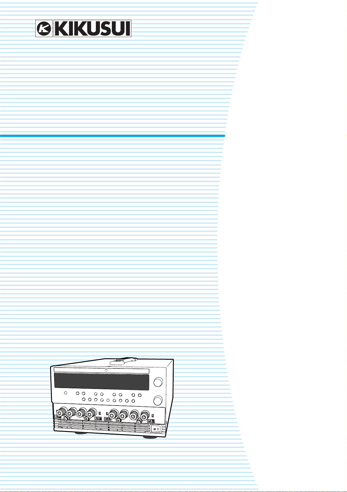
PMX32-3DU
PMX32-3TR
PMX32-2QU
User’s Manual
Multiple-output Regulated
DC Power Supply
PMX Series (Multiple-output)
Contents 5
Component Names 8
Installation 13
Basic Functions 26
External Control 60
Parallel Operation and Series
Operation 67
Maintenance 77
Specifications 85
Appendix 96
PART NO. IB032411
Jul. 2018
Page 2

These manuals provide an overview of the product and
About Manuals
HTMLHTML
紙紙
紙紙
notes on usage. They also explain how to configure it,
operate it, perform maintenance on it, and so on. Read
these manuals thoroughly before use, and use the product
properly.
Intended readers
These manuals are intended for users of this product and
their instructors. The manuals assume that the reader has
knowledge about power supplies.
Manual construction
Copyright
Reproduction and reprinting of this operation manual,
whole or partially, without our permission is prohibited.
Both unit specifications and manual contents are subject to
change without notice.
© Copyright 2018 Kikusui Electronics Corporation
• User’s manual (this manual)
This document is intended for first-time users of this
product. It provides an overview of the product, notes on
usage, and specifications. It also explains how to connect the product, configure the product, operate the
product, perform maintenance on the product, and so
on.
• Communication Interface Manual (partially in PDF)
This document contains details about remote control.
The interface manual is written for readers with sufficient
basic knowledge of how to control power supplies using
a PC.
• Packing list
The packing list shows the included accessories.
• Safety Information
This document contains general safety precautions.
Keep them in mind and make sure to observe them.
PDF and HTML files are included in the accompanying
CD-ROM. You can view the PDF files using Adobe
Reader.
Microsoft Internet Explorer or Google Chrome is required
to view the HTML files.
PDFPDF
PDFPDF
PDFPDF
Firmware versions that this manual covers
This manual applies to products with firmware versions
1.0X.
For information on how to check the firmware version, see
“Turning the POWER switch on” (p.21).
When contacting us about the product, please provide us
with:
The model (marked in the top section of the front panel)
Firmware version (p.21)
The serial number (marked on the rear panel)
Trademarks
Microsoft is a registered trademark or trademark of Microsoft Corporation in the United States and/or other countries.
Other company names and product names used in this
manual are generally trademarks or registered trademarks
of the respective companies.
2 User’s Manual PMX_MULTI
Page 3
The PMX series (multiple-output) is a compact multiple-
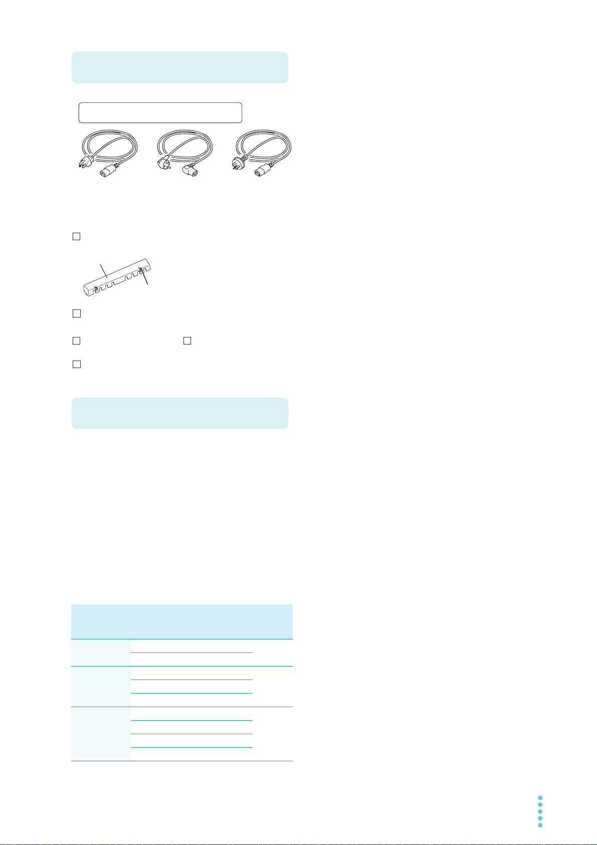
Accessories
or or
With screws (2 pcs.)
[M8-600-024]
[Q1-500-214]
Rating: 125 Vac/10 A
Plug: NEMA5-15
Length: approx. 2.5 m
[85-AA-0004]
Rating: 250 Vac/10 A
Plug: CEE7/7
Length: approx. 2.5 m
[85-10-1070]
Rating: 250 Vac/10 A
Plug: GB1002
Length: approx. 2.5 m
[85-10-0791]
Power cord (1 pc.)
CD-ROM (1 disc)
Packing list (1 copy)
Output terminal cover set (1 set)
Safety Information (1 copy)
The attached power cord varies depending on the
shipment destination.
Product Overview
output DC power supply whose outputs are isolated from
each other.
There are three models (types): two-output model (DU),
three-output model (TR), and four-output model (QU).
Because the PMX series comes standard with RS232C,
USB, and LAN (LXI compatible) communication functions,
it can easily be incorporated into a wide range of inspection systems.
It is best suitable for use in research and development and
production lines.
PMX series (multiple-output) model con-
figurations
Model Output
PMX32-3DU
(2CH)
PMX32-3TR
(3CH)
PMX32-2QU
(4CH)
terminal
CH1 32V 3A 192W
CH2 32 V 3 A
CH1 32V 3A 222W
CH2 32 V 3 A
CH3 6 V 5 A
CH1 32V 2A 218W
CH2 32 V 2 A
CH3 18 V 2.5 A
CH4 18 V 2.5 A
Rated
Output
Voltage
Rated
Output
Current
Rated
Output
Power
Features
In addition to basic constant current and constant voltage,
the PMX series (multiple-output) offers a variety of other
functions.
Each output isolated
Each output is isolated and safe.
High-resolution display
Display is possible with a high resolution at 1 mV or
1 mA, regardless of the output rating.
Output on/off for each channel
The output of each channel can be turned on or off, not
just all channels at once.
Switch between series connection and parallel connection with a single key
CH1 and CH2 can be connected in series or parallel.
Tracking control
The output of each channel can be simultaneously
changed to the same width or ratio (%).
On/off delay of each output
You can set the delay (DELAY TIME) from when the
OUTPUT ALL key is turned on or off to when the output
actually turns on or off. This is useful when you want to
turn the output on or off by setting a delay according to
the load characteristics.
Memory
You can save up to three sets of output settings (the
combination of the voltage, current, OVP, OCP, ondelay, and off-delay). You can simply select a memory
entry that you want to use rather than specifying the output value every time.
Simultaneous display of all channel statuses
In addition to voltage or current, output on/off and other
statuses are displayed for each channel.
Sensing function
Remote sensing stabilizes the output voltage across the
load by reducing the influence of voltage drops and
other effects caused by the load cable resistance.
Color liquid crystal display (LCD)
Allows easy-to-see display in color. The display shows
the voltage, current, operation, and status.
Standard RS232C, USB, and LAN (LXI compatible)
communication functions
Simultaneous remote control is possible through the
three available interfaces.
This makes it easy to incorporate the product into various inspection systems.
PMX_MULTI User’s Manual 3
Page 4
• In this manual, the PMX32-3DU, PMX32-3TR, and
Notations Used in This Manual
WARNING
CAUTION
Safety Precautions
Precautions Concerning Installation Location
PMX32-2QU multiple-output regulated DC power supplies are referred to as the PMX series (multiple-output)
or the PMX.
• The term “PC” is used to refer generally to both personal
computers and workstations.
• The screen captures and illustrations used in this text
may differ from the actual items.
• The following markings are used in this manual.
DANGER
Indicates an imminently hazardous situation which, if
ignored, will result in death or serious injury.
Indicates a potentially hazardous situation which, if
ignored, could result in death or serious injury.
Indicates a potentially hazardous situation which, if
ignored, may result in slight injury or damage to the
product or other property.
Indicates information that you should know.
Indicates a reference manual (CD-ROM) containing
detailed information.
When installing this product, be sure to observe the precautions provided in the Safety information manual. Items
specific to this product are given below.
• The rear panel may become hot during operation. If you
touch it, you may burn yourself.
When installing this product, be sure to observe the “Precautions When Choosing the Installation Location” in the
Safety information manual. Items specific to this product
are given below.
• When installing this product, be sure to observe the temperature and humidity ranges indicated below.
Operating temperature range: 0 °C to 40 °C
Operating humidity range: 20 %rh to 85 %rh (no condensation)
• When storing this product, be sure to observe the temperature and humidity ranges indicated below.
Storage temperature range: -25 °C to 70 °C
Storage humidity range: 90 %rh or less (no condensation)
• Do not install the product vertically.
It may cause injury to the operator or damage to the
product when it falls down.
>
Indicates the hierarchy of items you need to select. The
item to the left of this symbol indicates a higher level
item.
CFxx: x
“CF” indicates that this is a CONFIG parameter. The two
digits after CF indicate the CONFIG parameter number.
The value after the colon indicates the selected setting.
SHIFT+key name
Indicates an operation that requires you to press a key
while holding down SHIFT.
4 User’s Manual PMX_MULTI
Page 5

Contents
About Manuals ...................................................2
Accessories ........................................................3
Product Overview ...............................................3
Notations Used in This Manual...........................4
Safety Precautions .............................................4
Precautions Concerning Installation Location ....4
Component Names ............................................8
Installation
Connecting the Power Cord .............................13
Load Considerations ........................................14
Selecting the Load Cables ...............................16
Output Terminal Insulation ...............................17
When the output terminal is not grounded (floating).
17
When the output terminal is grounded.................. 18
Connecting to the Output Terminals.................19
Checking Whether the Power Is On or Off .......21
Turning the POWER switch on............................. 21
Turning off the POWER switch.............................22
Sensing Function..............................................23
Local sensing........................................................ 23
Remote sensing.................................................... 23
Basic Functions
Locking the Panel Controls (Key Lock) ............54
Tracking Function.............................................54
Remote Control ................................................59
External Control
CONTROL TERMINAL ....................................61
Connecting the CONTROL TERMINAL ............... 61
Pin arrangement of the CONTROL TERMINAL ... 62
Output On/Off Control ......................................63
Alarm Input .......................................................65
External monitoring of the operating status......66
Parallel Operation and
Series Operation
Overview of Parallel Operation ........................67
Parallel Operation Functions ................................ 67
Connections for parallel operation........................ 69
Configuration for parallel operation ...................... 70
Starting parallel operation .................................... 70
Overview of Series Operation ..........................72
Series Operation Functions.................................. 72
Connection for series operation ...........................74
Configuration for series operation ........................ 75
Starting series operation ...................................... 75
Panel Display ...................................................26
Panel Operations..............................................28
Output Operation ..............................................29
Output on/ off setting at power-on ........................29
Output-on startup state parameter .......................29
output-on delay/ off delay .....................................30
CV Power Supply and CC Power Supply.........34
Using the PMX as a CV or CC Power Supply36
Protection Functions and Alarms......................37
Alarm occurrence and clearing alarms .................37
Setting and displaying the protection functions ....38
CONFIG Settings .............................................42
CONFIG parameter details................................... 45
Memory Function..............................................52
Saving settings ..................................................... 52
Recalling settings .................................................53
PMX_MULTI User’s Manual 5
Maintenance
Calibration Overview ............................................ 77
Connection ........................................................... 78
Calibration procedure ........................................... 79
Connection (series operation and parallel operation)
82
Calibration procedure (series operation and parallel
operation) ............................................................. 83
Page 6

Specifications
AC input ................................................................85
Output ...................................................................86
Display function .....................................................88
Protection function ................................................89
Signal output .........................................................89
Control functions ...................................................90
Sensing .................................................................90
Parallel operation and series operation.................91
Other functions......................................................92
Interface ................................................................93
General specifications...........................................94
External dimensions ..............................................95
Appendix
Factory Default Settings .................................. 96
Options ............................................................ 97
Rack mounting options..........................................97
Troubleshooting............................................... 99
Index.............................................................. 103
6 User’s Manual PMX_MULTI
Page 7

This page is intentionally blank.
PMX_MULTI User’s Manual 7
Page 8
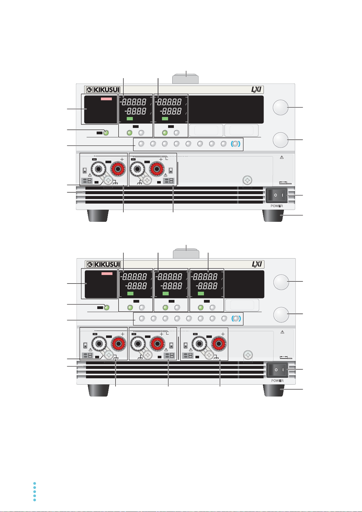
Component Names
PMX32-3TR
PMX32-3DU
9
8
7
4
3
2
Controls
2
Controls
CH1
Display
CH2
Display
CH1
Display
CH2
Display
CH3
Display
CH1
Output terminal area
CH2
Output terminal area
CH3
Output terminal area
CH1
Output terminal area
CH2
Output terminal area
5
1
1
6
9
8
7
4
3
5
6
POWER
FINE
FINE
TRACK DELAY
CBA
ALM CLR
DELAY SETTRACK SET
PRLSER
OVP࣭OCP
SET LOCKCONFIG
SELECTOUTPUT SELECTOUTPUT SELECTOUTPUT
CH3
SELECTOUTPUT
CH4
OUTPUT
PMX32-3DU
0-32V 2A
CURRENT
VOLTAGE
LOCAL
SHIFT
MULTIPLE OUTPUT DC POWER SUPPLY
CV
V
s
OFF
CC
A
s
ON
PRLSER
TRACKING 12
LOCK
REMOTE
LAN LAN
DEL AY
DEL AY SET
SET OVP࣭OCP
PRESET A BC
ALARM
CV
V
s
OFF
CC
A
s
ON
PRLSER
TRACKING 12
CV
V
s
OFF
CC
A
s
ON
PARASERI
TRACKING 12
CV
V
s
OFF
CC
A
s
ON
PARASERI
TRACKING 12
%%%%
%%%%
AWG 20-28
STRIP
-
GAUGE
8mm
DC
OUTPUT
SER
PRL
0
-
32V 0-6A
0
-
64V 0-3A
0-32V 0-3A 0-32V 0-3A
SENSE 2
SENSE 1
OFF
ON
OFF
ON
-
S
+
S
-
S
+
S
POWER
FINE
FINE
TRACK DELAY
CBA
ALM CLR
DELAY SETTRACK SET
PRLSER
OVP࣭OCP
SET LOCKCONFIG
SELECTOUTPUT
CH1
SELECTOUTPUT
CH2
SELECTOUTPUT
CH3
SELECTOUTPUT
CH4
OUTPUT
ALL
PMX32-3TR
0-32V 2A
CURRENT
VOLTAGE
LOCAL
SHIFT
MULTIPLE OUTPUT DC POWER SUPPLY
CV
V
s
OFF
CC
A
s
ON
PRLSER
TRACKING 12
LOCK
REMOTE
LAN LAN
DEL AY
DEL AY SET
SET OVP࣭OCP
PRESET A BC
ALARM
CV
V
s
OFF
CC
A
s
ON
PRLSER
TRACKING 12
CV
V
s
OFF
CC
A
s
ON
PRLSER
TRACKING 12
CV
V
s
OFF
CC
A
s
ON
PARASERI
TRACKING 12
%%%%
%%%%
AWG 20-28
STRIP
-
GAUGE
8mm
DC
OUTPUT
SER
PRL
0
-
32V 0-6A
0
-
64V 0-3A
0-32V 0-3A
CH1
0-32V 0-3A
CH2 CH3
0
-
6V 0-5A
SENSE 3
-
S
SENSE 2
SENSE 1
OFFONOFF
ON
OFF
ON
+
S
-
S
+
S
-
S
+
S
CH1 CH2
ALL
CH1 CH2
Front panel
8 User’s Manual PMX_MULTI
Page 9
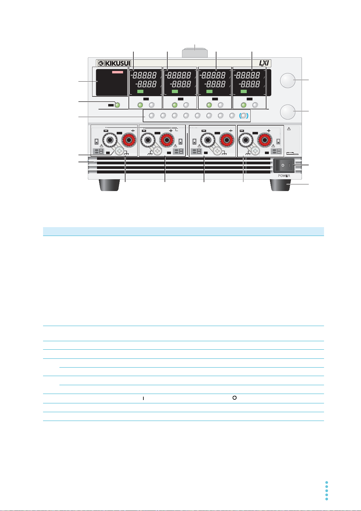
PMX32-2QU
9
8
7
4
3
5
1
6
CH1
Display
CH2
Display
CH3
Display
CH4
Display
CH1
Output terminal
area
CH2
Output terminal
area
CH3
Output terminal
area
CH4
Output terminal
area
2
Controls
POWER
TRACK DELAY
CBA
ALM CLR
DELAY SETTRACK SET
PRLSER
OVP࣭OCP
SET LOCKCONFIG
SELECTOUTPUT
CH1
SELECTOUTPUT
CH2
SELECTOUTPUT
CH3
SELECTOUTPUT
CH4
OUTPUT
ALL
PMX32-2QU
0-32V 2A
MULTIPLE OUTPUT DC POWER SUPPLY
CURRENT
FINE
FINE
VOLTAGE
LOCAL
SHIFT
CV
V
s
OFF
CC
A
s
ON
PRLSER
TRACKING 12
LOCK
REMOTE
LAN
LAN
DEL AY
DEL AY SET
SET OVP࣭OCP
PRESET A BC
ALARM
CV
V
s
OFF
CC
A
s
ON
PRLSER
TRACKING 12
CV
V
s
OFF
CC
A
s
ON
PRLSER
TRACKING 12
CV
V
s
OFF
CC
A
s
ON
PRLSER
TRACKING 12
%%%%
%%%%
0-32V 0-2A
CH1
0-32V 0-2A
CH2 CH3
0
-
18V 0-2.5A
CH4
0
-
18V 0-2.5A
SENSE 3
-
S
AWG 20
-
28
STRIP
-
GAUGE
8mm
SER
PRL
DC
OUTPUT
0-32V 0-4A
0
-
64V 0-2A
SENSE 2
SENSE 1 SENSE 4
OFF
ON
OFF
ON
OFF
ON
OFF
ON
+
S
-
S
+
S
-
S
+
S
-
S
+
S
No. Name Function See
1 Status display area ALARM: Appears in red when a protection function is activated.
—
SET: Appears when setting or viewing the output voltage or output current.
OVP•OCP: Appears when the overvoltage protection (OVP) or overcurrent pro-
tection (OCP) trip point is being set.
DELAY: Appears when output-on delay/ off delay is in progress. Blinks when
delay is in progress.
DELAY SET: Appears when output-on delay/ off delay is being set.
PRESET A/ B/ C: Appears when memory A, B, or C is being recalled or saved.
LOCK: Appears when the key lock is enabled.
REMOTE: Appears when the product is being controlled remotely.
LAN (green): Appears in the no fault state. Blinks in the identify state.
LAN (red): Appears in the fault state. Blinks in the standby state.
2 OUTPUT ALL key Turns the output on or off on all channels simultaneously. Starts the output-on
p.29
delay/ off delay.
3 Short bar Connects the output terminal to the chassis terminal. —
4 Air inlet Inlet holes for cooling. —
5 VOLTAGE knob Used to set the voltage value or change the value of a CONFIG parameter. p.28
6 CURRENT knob Used to set the current value or change the value of a CONFIG parameter. p.28
7 POWER switch
8 Feet Four casters attached to the bottom of the product. p.98
9 Handle Handle for carrying the product. p.98
FINE Used to make fine voltage value adjustments. p.28
FINE Used to make fine current value adjustments. p.28
Press the ( ) side to switch the power on, and the ( ) side to switch the power off.
p.21
PMX_MULTI User’s Manual 9
Page 10
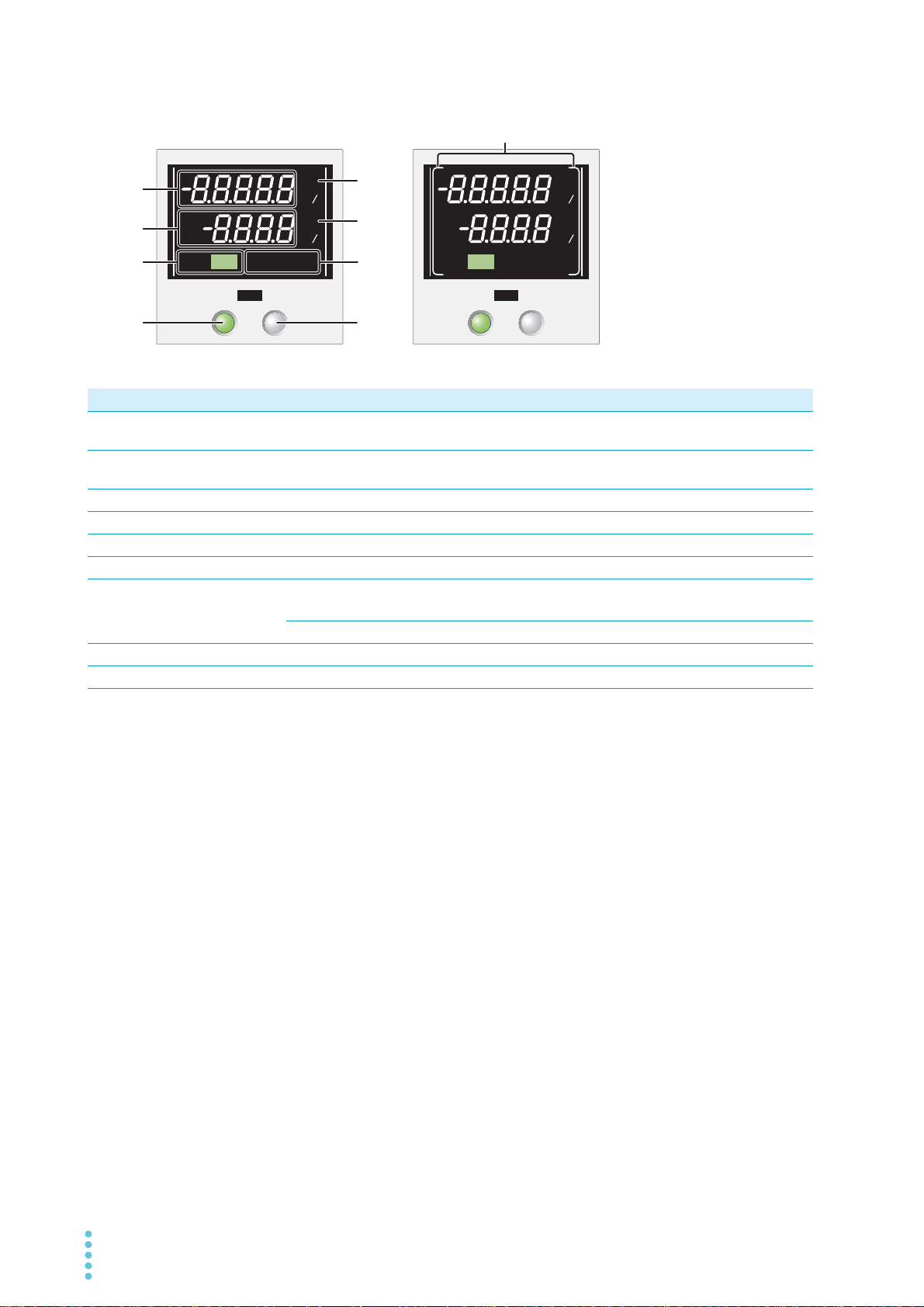
CH1/CH2/CH3/CH4 display area
SELECTOUTPUT
CHX
SELECTOUTPUT
CHX
CV
V
s
OFF
CC
A
s
ON
PRLSER
TRACK ING12
%
%
CV
V
s
OFF
CC
A
s
ON
PRLSER
TRACK ING12
%
%
1
2
3
4
5
6
7
8
9
No. Name Function See
1 Voltmeter Displays the voltage, CONFIG parameter number, alarm, output-on delay time, or
the amount of voltage change of tracking function 2.
2 Ammeter Displays the current, CONFIG parameter value, cause of alarms, output-off delay
time, or the amount of current change of tracking function 2.
3 Output display OFF: appears when output is off, ON: appears when output is on (green) p.29
4 OUTPUT key Turns on or off the output of each channel. p.29
5 CV Appears in constant voltage mode. p.36
6 CC Appears in constant current mode. p.36
7 Status indicators SER: Appears during series operation.
PRL: Appears during parallel operation.
TRACKING12: Appears when tracking function 1 or tracking function 2 is in use. p.54
8 SELECT key Selects the channel. —
9 Selection display Appears when selected with the SELECT key. —
p.26
p.26
—
10 User’s Manual PMX_MULTI
Page 11
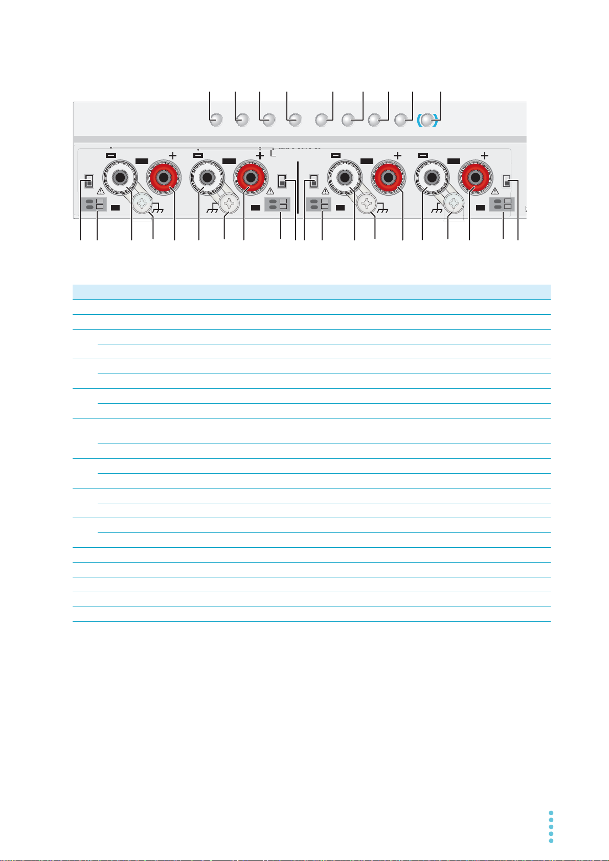
Control area and output terminal area
TRACK DELAY
CBA
ALM CLR
DELAY SETTRACK SET
PRLSER
OVP࣭OCP
SET LOCKCONFIG LOCAL
SHIFT
0-32V 0-2A
CH1
0-32V 0-2A
CH2 CH3
0
-
18V 0-2.5A
CH4
0
-
18V 0-2.5A
SENSE 3
-
S
A
S
SER
PRL
O
0-32V 0-4A
0
-
64V 0-2A
SENSE 2
SENSE 1 SENSE 4
OFF
ON
OFF
ON
OFF
ON
OFF
ON
+
S
-
S
+
S
-
S
+
S
-
S
+
S
1234 5 678 9
10 11 12 1413
11 10 1012 1413 1112 141310 11 12 1413
No. Name Function See
1 SER key Turns on or off parallel operation. p.75
2 PRL key Turns on or off series operation. p.70
3 TRACK key Turns on or off the tracking function. p.54
TRACK SET key Switches between tracking function 1 and tracking function 2. p.54
4 DELAY key Turns on or off the delay function. p.33
DELAY SET key Used to set or display the output-on delay/ off delay time. p.32
5 SET key Used to set or display the output voltage or output current. p.26
ALARM CLR key Releases the activated state (alarm) of protection functions. p.37
6 OVP•OCP key Used to set or display the overvoltage protection (OVP) or overcurrent protection
(OCP) trip point.
A Recalls or saves memory A values. p.52
7 CONFIG key Used to configure various operating conditions (CONFIG). p.42
B Recalls or saves memory B values. p.52
8 LOCK key Turns on or off the key lock. p.54
C Recalls or saves memory C values. p.52
9 LOCAL key Switches between local mode and remote mode. p.59
SHIFT key Used to enable the functions that are written in blue characters below the key. —
10 SENSE switch Used to turn remote sensing on and off. p.23
11 Sensing terminal Terminals to connect the sensing cables to. p.24
12 DC OUTPUT− Negative output terminal p.19
Chassis terminal A connector for grounding the output. —
13
DC OUTPUT+ Positive output terminal p.19
14
p.38
PMX_MULTI User’s Manual 11
Page 12
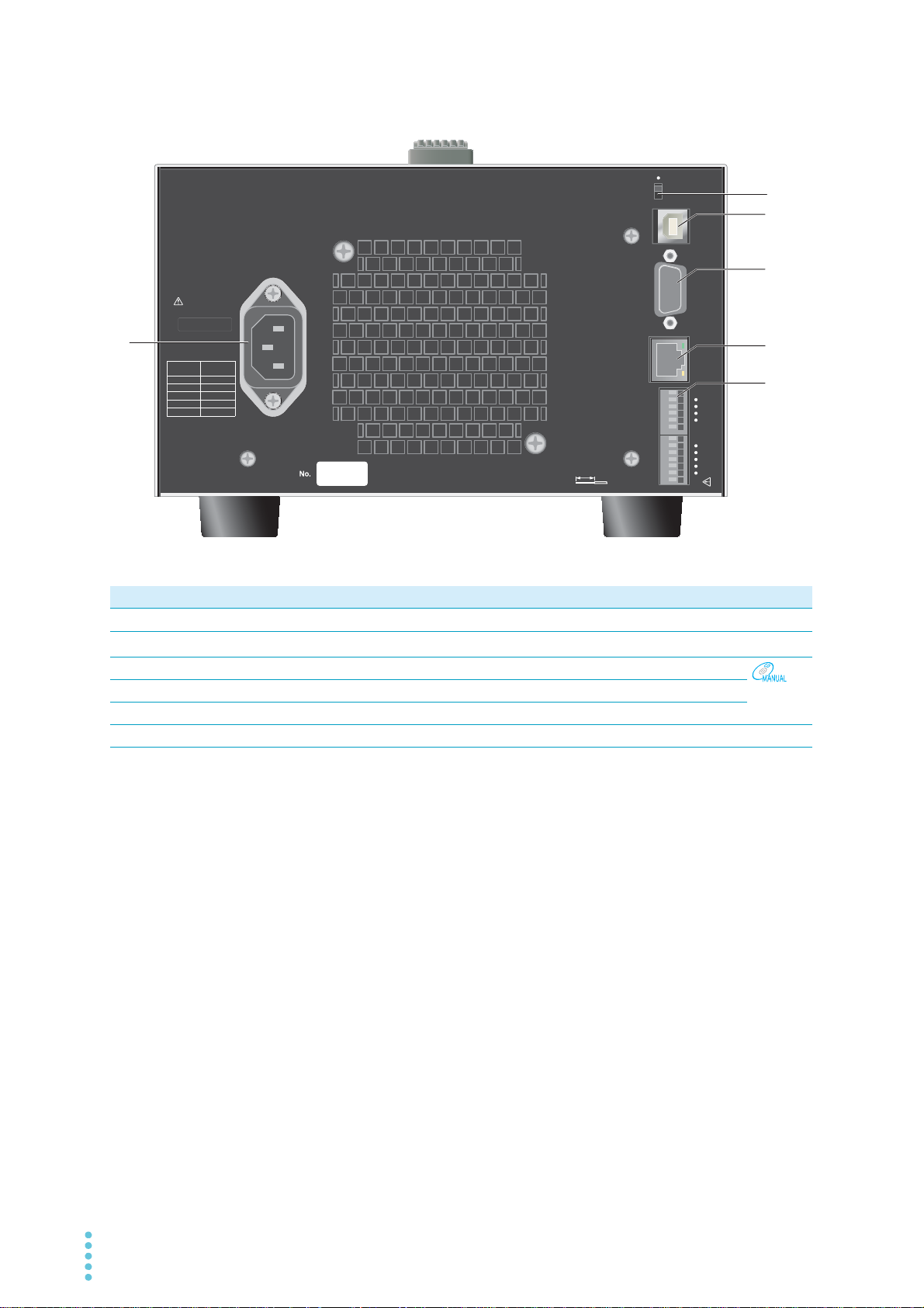
Rear Panel
50-60Hz
AC INPU T
KIKUSUI ELECTRONICS CORP. MADE IN CHINA
LINE
VOLTAGE
100V
117V
200V
217V
234V
SETTING
SUPPLY
RS232C USBLAN
S1
17813
CONTROL TERMINAL
1. CH1 OUT ON STATUS
2. CH2 OUT ON STATUS
3. CH3 OUT ON STATUS
(
TR QU
)
4. CH4 OUT ON STATUS
(
QU
)
8. CH1 OUT ON
/
OFF CONTROL
9. CH2 OUT ON
/
OFF CONTROL
10. CH3 OUT ON
/
OFF CONTROL
(
TR QU
)
11. CH4 OUT ON
/
OFF CONTROL
(
QU
)
AWG 20-28
STRIP GAUGE
8mm
1
5
6
4
2
3
No. Name Function See
1 AC INPUT AC inlet p.13
2
S1 switch
*1
Maintenance switch. —
3 USB port USB port for remote control.
4 RS232C port RS232C port for remote control.
5 LAN port LAN port for remote control.
6 CONTROL TERMINAL External control terminal block.
*1. Kikusui service engineers use this switch only during maintenance and servicing. Normally, the switch is on the
side of ●.
12 User’s Manual PMX_MULTI
Interface
manual
p.61
Page 13
Installation
50-60Hz
LINE
VOLTAGE
100V
117V
200V
217V
234V
SETTING
SUPPLY
Connecting the Power Cord
This product is designed as an equipment of IEC Overvoltage Category II (energy-consuming equipment
supplied from a fixed installation).
Protective conductor current (at 257.4 Vac, 60 Hz) : Approx. 1 mA.
WARNING
Check that the AC power line meets the nominal input rating of the product.
1
The product can receive a nominal power supply voltage of 100 Vac, 117 Vac, 200 Vac, 217 Vac,
or 234 Vac at a frequency of 50 Hz or 60 Hz.
Risk of electric shock.
• This product is IEC Safety Class I equipment (equipment with a protective conductor terminal). To prevent electric shock, be sure to connect the protective conductor
terminal of the product to electrical ground (safety ground).
• The product isp grounded through the power cord ground wire. Connect the protective conductor terminal to earth ground.
• Use the supplied power cord to connect to the AC line.
If the supplied power cord cannot be used because the rated voltage or the plug shape is
incompatible, have a qualified engineer replace it with an appropriate power cord that is 3
m or less in length. If obtaining a power cord is difficult, contact your Kikusui agent or distributor.
• The power cord with a plug can be used to disconnect the product from the AC power line
in an emergency.
• Secure adequate space around the power plug. Do not insert the power plug to an outlet
where accessibility to the plug is poor. And, do not place objects near the outlet that would
result in poor accessibility to the plug.
• Do not use the supplied power cord with other instruments.
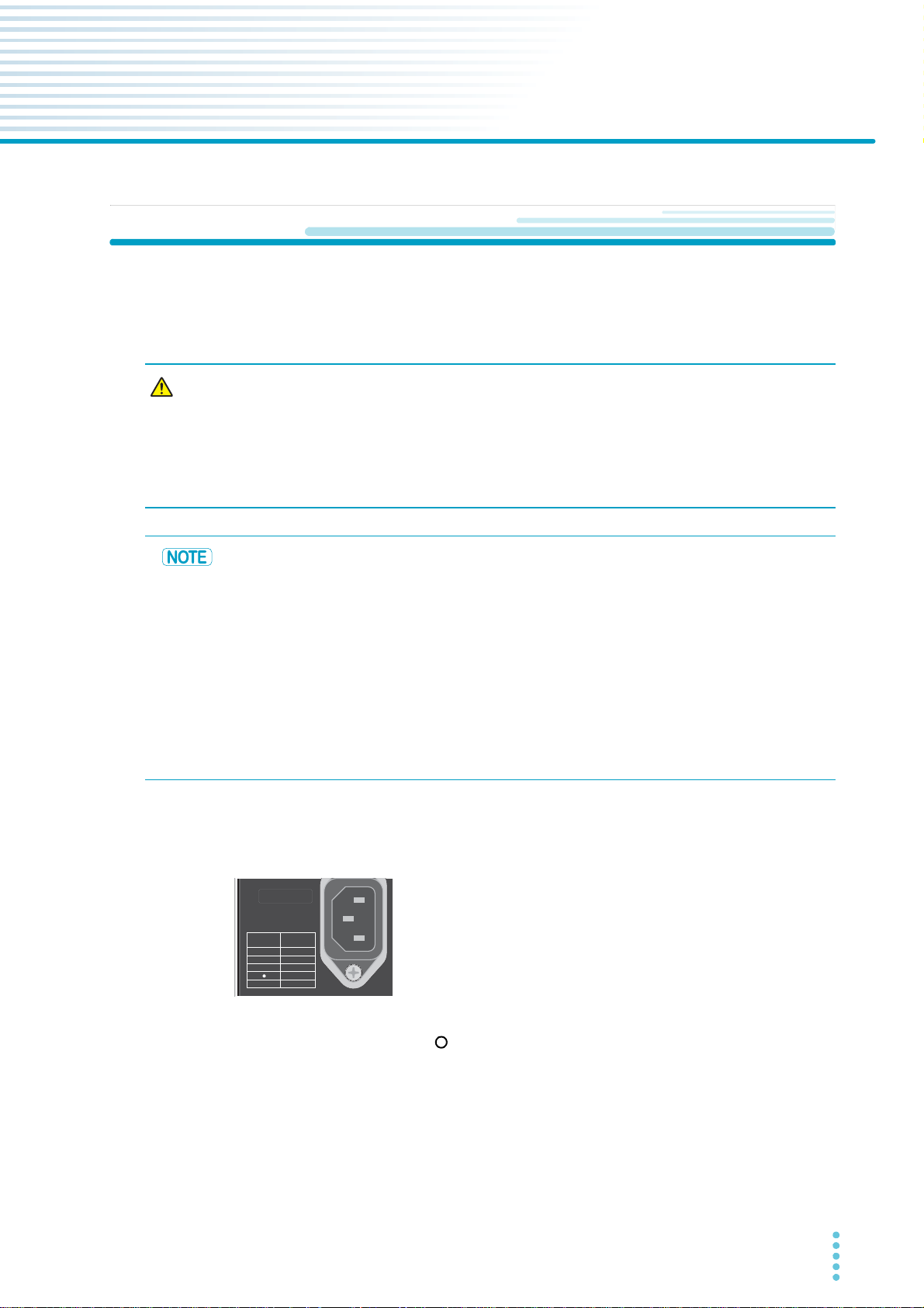
The supply voltage is set before factory shipment by a Kikusui service engineer. A mark is indicated to the left of the appropriate voltage.
Be sure to check the nominal input rating before connecting the
power cord.
Example of 217 Vac supply voltage
Turn the POWER switch off ( ).
2
Connect the power cord to the AC INPUT inlet on the rear panel.
3
Connect the power cord plug to an outlet with a ground terminal.
4
This completes the connections.
PMX_MULTI User’s Manual 13
Page 14
Installation
Constant current setting
Ammeter reading (mean value)
Constant current setting
Ammeter reading (mean value)
O
RD
EO
Equivalent circuit of the product
Regenerative load
Load
+
0
waveform
+IO
Irp
RD>ȍ@
EO>9@
Irp[A]
RD: Reverse current bypass dummy load
E
O: Output voltage
I
rp: Maximum reverse current
CAUTION
Load Considerations
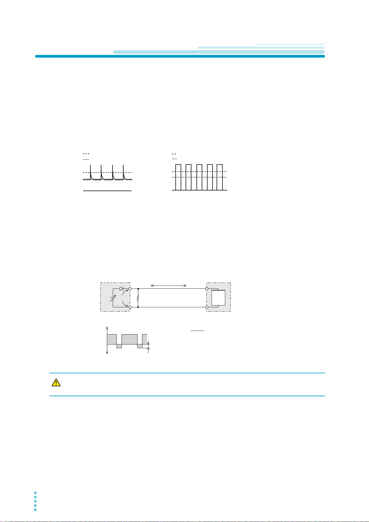
Note that the output will become unstable if the following types of loads are connected.
Loads with peak current or pulse-shaped current
The product only indicates mean values. Even when the indicated value is less than or equal to the set
constant current, the peak values may exceed the set constant current. If this happens, the product is
instantaneously put into constant-current mode, and the output voltage drops.
For these types of loads, you must increase the set constant current or increase the current capacity.
Load current with peaks Pulse-shaped load current
Loads that generate reverse current to the power supply
The product cannot absorb reverse current from the load. Therefore, if a regenerative load (such as an
inverter, converter, or transformer) is connected, the output voltage increases and becomes unstable. This
can cause a malfunction.
For these types of loads, connect a resistor (R
current. However, the amount of current to the load decreases by Irp.
Output current
-IO
Reverse current
Use a resistor with sufficient rated power for RD. If a resistor with insufficient rated power for
the circuit is used, resistor R
D) as shown in the following figure to bypass the reverse
I
D will burn out.
14 User’s Manual PMX_MULTI
Page 15
Installation | Load Considerations
PMX
Load with accumulated energy
DRP: Reverse-current-protection diode
D
RP
CAUTION
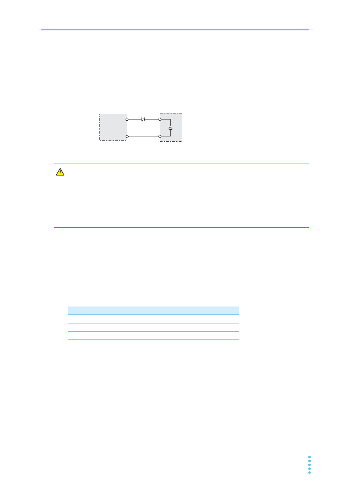
Loads with accumulated energy
Connecting a load with accumulated energy, such as a battery, to the product may cause current to flow
from the load to the internal circuit of the product. This current may damage the product or reduce the life
of the load.
For this type of load, connect a reverse-current-prevention diode (D
in series as shown in the following figure.
This cannot be used in conjunction with remote sensing.
• To protect the load and the product, use a DRP that conforms to the following specifications.
Reverse voltage withstand capacity: At least twice the rated output voltage of the
product.
Forward current capacity: 3 to 10 times the rated output current of the product.
A diode with small loss.
• Be sure to take into account the heat generated by D
heat dissipation.
RP) between the product and the load
RP. DRP will burn out with inadequate
Sink current from an external voltage source
The current varies depending on the voltage of the external voltage source.
The sink current is reduced at a low output terminal voltage. Hardly any sink current flows near 0 V.
The sink current indicated here is the value obtained when an external voltage with the same value as the
rated voltage is connected.
Sink current (TYP)
Model CH1 CH2 CH3 CH4
PMX32-3DU 43 mA 43 mA − −
PMX32-3TR 43mA 43mA 27mA −
PMX32-2QU 43mA 43mA 36mA 36mA
PMX_MULTI User’s Manual 15
Page 16
Installation
WARNING
CAUTION
Selecting the Load Cables
Risk of fire.
• Use load cables whose capacity is adequate for the product’s rated output current.
• The output connector and its surrounding area become hot. Use cables whose covers have heat resistance at 85 °C and higher.
Risk of electric shock.
• Use load cables with a voltage rating that meets or exceeds the product’s isolation
voltage. For details on the product’s isolation voltage, see 「Specifications」 (p.85).
• Use load cables with a core diameter that is appropriate for the amount of current being
used and with sturdy, flame-resistant insulation.
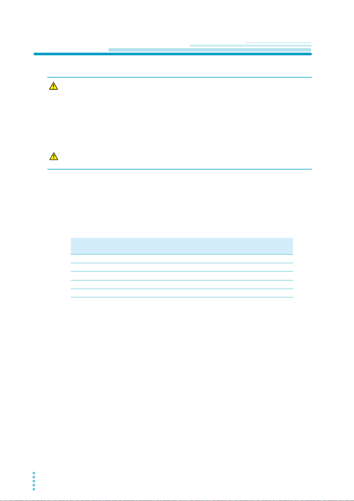
Current capacity of load cables
A wire’s temperature is determined by the resistive loss based on the current, the ambient temperature,
and the wire’s external thermal resistance. The following table shows the current capacity of heat-resistant
vinyl wires that have a maximum allowable temperature of 60 °C when one of the wires is separated and
stretched out horizontally in air in an ambient temperature of 30 °C. The current must be reduced under
certain conditions, such as when vinyl wires that have a low heat resistance are used, when the ambient
temperature is 30 °C or greater, or when wires are bundled together and little heat is radiated.
Nominal cross-sec-
tional area (mm
0.9 18 (0.82) 17 4
1.25 16 (1.31) 19 6
2 14 (2.08) 27 10
3.5 12 (3.31) 37 -
5.5 10 (5.26) 49 20
*1. * Excerpt from Japanese laws related to electrical equipment.
AWG (reference cross-sec-
2
)
tional area; mm
2
)
Allowable current*1 (A)
(Ta = 30°C)
Kikusui-recommended current (A)
Taking measures against noise
When connecting wires that have the same heat resistance, separating the wires as much as possible to
increase heat radiation enables a greater amount of current to flow. However, wiring the + (positive) and (negative) output wires of the load cable side by side or bundling them together is more effective against
unwanted noise. The Kikusui-recommended currents shown in the above table are allowable currents that
have been reduced in consideration of the potential bundling of load cables. Use these values as a guideline when connecting load cables.
Limitations of the remote sensing function
All wires have resistance. As the wire becomes longer or the current becomes larger, the voltage drop in
the wire becomes greater. This results in a smaller voltage being applied at the load end. This product has
a sensing function that compensates for this voltage drop up to approximately 0.6 V for a single line (p.23).
If the voltage drop exceeds this level, use wires that have a greater cross-sectional area.
16 User’s Manual PMX_MULTI
Page 17
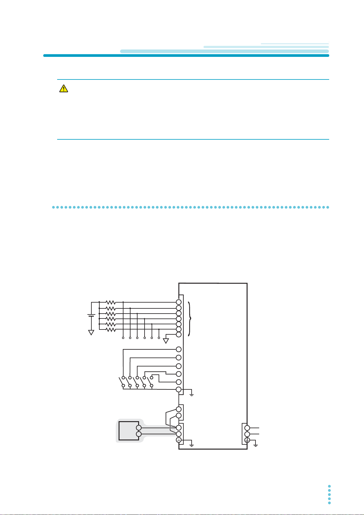
Output Terminal Insulation
+
–
+
+S
–S
–
+
–
10
11
12
13
6
7
5
4
3
2
1
8
9
AC
INPUT
DC
OUTPUT
J1
SENS
L
N
Isolated from the chassis
terminal and output
terminal
Chassis electric potential
Load
PMX
Installation
WARNING
Risk of electric shock. For safety reasons, even if the output terminal is grounded,
make sure that the insulation capacity of the output terminal (including the sensing
terminal) is greater than or equal to the isolation voltage of this product.
For details on the isolation voltage of each model, see 「Specifications」 (p.85).
If you cannot obtain a cable with sufficient rated voltage, secure adequate withstand
voltage by passing the cable through an insulation tube with a withstand voltage
greater than the isolation voltage of the PMX seres (multiple-output).
The cable and load that are connected to the output terminal (including the sensing terminal) must have an
insulation capacity that is greater than or equal to the isolation voltage of the PMX seres (multiple-output)
with respect to the chassis. Isolation voltage indicates the maximum allowed voltage that appears across
the output terminal of the power supply unit and the protective conductor terminal (chassis terminal).
When the output terminal is not grounded (floating)
The output terminal of the PMX seres (multiple-output) is isolated from the protective conductor terminal. If
you connect the GND wire of the power cord to the ground terminal of the switchboard, the chassis of the
product is set to ground potential.
Pins 1 to 7 of the CONTROL TERMINAL on the rear panel are isolated from the chassis terminal and output terminal of this product. Cables and devices that are connected to these pins must have an insulation
capacity greater than or equal to the isolation voltage of the PMX seres (multiple-output).
Vex t
PMX_MULTI User’s Manual 17
Page 18
Installation | Output Terminal Insulation
+
–
+
+S
–S
–
+
–
10
11
12
13
6
7
5
4
3
2
1
8
9
AC
INPUT
DC
OUTPUT
J1
SENS
L
N
Isolated from the chassis
terminal and output
terminal
Chassis electric potential
Load
PMX
Vex t
Short bar
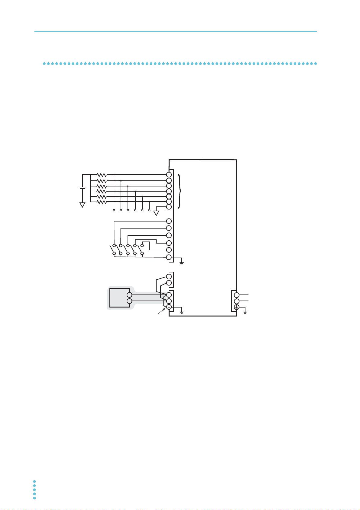
When the output terminal is grounded
If the positive output terminal is connected to the chassis terminal, the positive output terminal is at ground
potential. The cable and load that are connected to the output terminal (including the sensing terminal) will
only require an insulation capacity that is greater than or equal to the maximum output voltage of the PMX
seres (multiple-output) with respect to the chassis.
The same holds true when the negative terminal is connected to the chassis terminal. The cable and load
require an insulation capacity that is greater than or equal to the maximum output voltage of the PMX
seres (multiple-output).
For safety reasons, connect one of the output terminals to the chassis terminal unless your application
requires the output terminals to be floating.
18 User’s Manual PMX_MULTI
Page 19
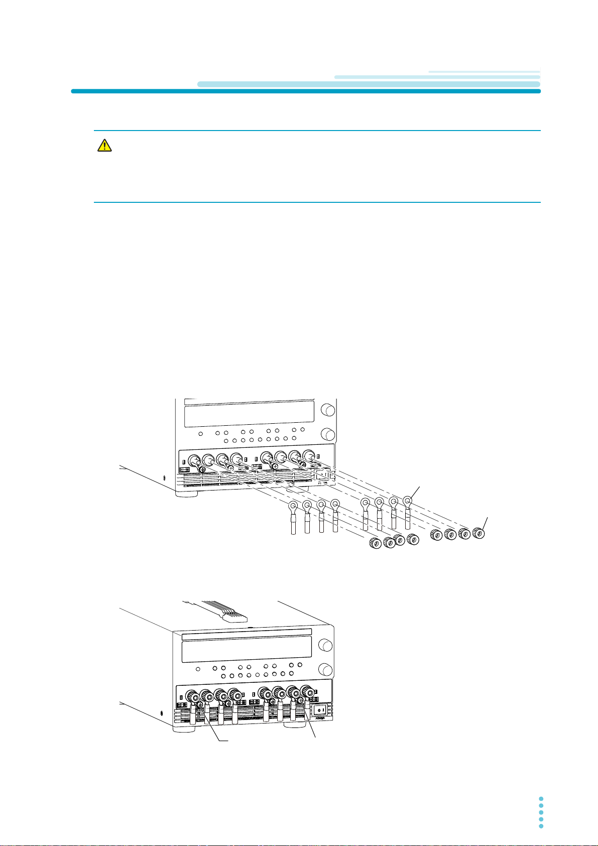
Connecting to the Output Terminals
M6
Crimping terminal
Output terminal knob
Example of PMX32-2QU
To attach the output terminal cover,
remove these screws.
Example of PMX32-2QU
Installation
WARNING
When using the sensing function, connect the sensing cables before connecting the load cables to the output terminals.
1
2
3
Risk of electric shock.
• Turn the POWER switch off before you touch the output terminals.
• Regardless of whether load cables are connected to the output terminals, be sure to
attach the output terminal cover before turning the POWER switch on.
Turn the POWER switch off.
Attach crimping terminals to the load cables.
Remove the knobs once, and attach the load cables to the output terminals.
Connect the short bar to the negative or positive output terminal.
If you are not grounding the output terminal (leaving it floating), follow the instructions in see “When
the output terminal is not grounded (floating)” on page 17 before use.
To reduce the influence of noise on the output, keep the cables as short as possible. If possible,
twist the positive and negative load cables.
To attach the output terminal cover, remove the chassis terminal screws on the out-
4
sides.
PMX_MULTI User’s Manual 19
Page 20
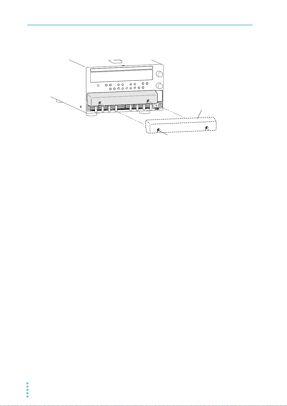
Installation | Connecting to the Output Terminals
Output terminal cover
Output terminal cover screw
Example of PMX32-2QU
Attach the output terminal cover.
5
Attach the output terminal cover using the screws included with the output terminal cover.
This completes the connections.
20 User’s Manual PMX_MULTI
Page 21
Installation
CAUTION
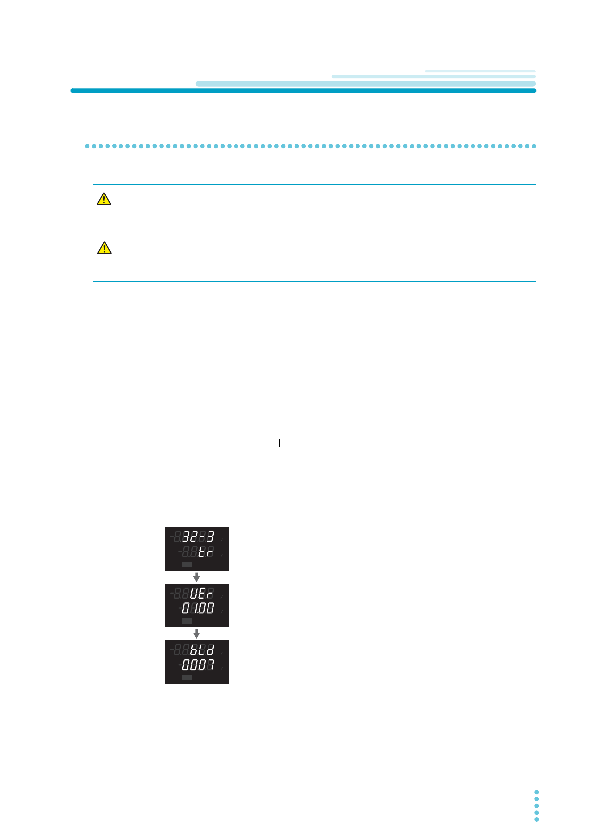
Firmware version
(Version 1.00 in this example)
Rated voltage, rated current, and type
(Example of PMX32-3TR)
Build number
(Build number BLD 0007 in this example)
CV
V
s
OFF
CC
A
s
ON
PARASERI
TRACKING 12
%
%
CV
V
s
OFF
CC
A
s
ON
PARASERI
TRACKING 12
%
%
CV
V
s
OFF
CC
A
s
ON
PARASERI
TRACKING 12
%
%
Checking Whether the Power Is On or Off
Turning the POWER switch on
WARNING
Risk of electric shock. Regardless of whether load cables are connected to the output
terminals, be sure to attach the output terminal cover before turning the POWER
switch on.
Risk of damage to load.
If the product is configured to turn on the output when the POWER switch is turned on in
CONFIG settings, set an appropriate OVP or OCP value before connecting a different load.
If the POWER switch is turned on for the first time after purchase, the product starts in the factory default
condition (p.96 ). Subsequent times that you turn the product on, it starts with the panel settings (excluding
the output on/off setting) that were in use immediately before the POWER switch was turned off.
You can use the CONFIG settings (CF01) to select the output state of the product when the POWER
switch is turned on (p.45).
Check that the power cord is connected correctly.
1
Check that the output terminal cover is attached (p.19).
2
When the product is shipped from the factory, the output terminal cover is not attached.
Turn the POWER switch on ( ).
3
All the indicators on the front panel turn on, and then the CH2 voltmeter and ammeter display the
following information in sequence: the rated voltage, rated current, and type, the firmware version
number, and then the build number. Each item is displayed for approximately 1 second.
After a few seconds, the product enters the operation standby state (the measured value is displayed).
PMX_MULTI User’s Manual 21
Page 22
Installation | Checking Whether the Power Is On or Off
CAUTION
Inrush current
When the POWER switch is turned on, an inrush current flows. Check that sufficient current capacity is
available in the AC power line or the switchboard, particularly if you are using multiple units and turning on
their POWER switches simultaneously. For the inrush current of each model, see “Specifications” (p.85).
Turning off the POWER switch
Turn the POWER switch off ( ).
This product saves the panel settings (except the output on/off setting) that were in use immediately
before the POWER switch was turned off.
You can use the CONFIG settings (CF01) to select the output state of the product when the POWER
switch is turned on (p.45).
If the POWER switch is turned off immediately after the settings have been changed, the last settings may
not be stored.
If you want to turn the POWER switch back on, wait at least 10 seconds after the panel display turns off. Repeatedly turning the POWER switch on and off at short intervals can cause
damage to the internal circuit. Furthermore, this will shorten the service life of the POWER
switch and the internal input fuse.
In some cases, the keys may become uncontrollable or a malfunction may occur in the alarm
indicators or the like. Turn the POWER switch off once and then back on.
22 User’s Manual PMX_MULTI
Page 23
Sensing Function
Sensing
switch
OFF
ON
+
–
+S
-S
Output terminal
Chassis terminal
Sensing terminal
PMX
Load
OFF position
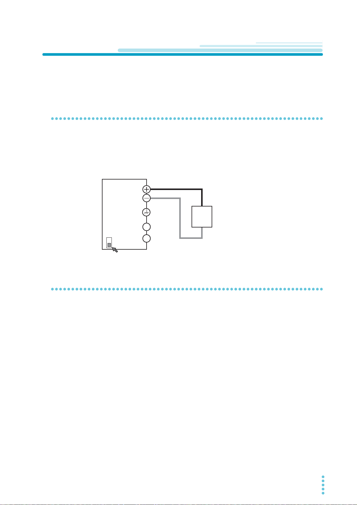
There are two types of sensing: local sensing and remote sensing.
By factory default, the product is set to local sensing (the SENSE switch is set to off).
Local sensing
Use local sensing when the cable to the load is short.
Local sensing does not compensate for the voltage drop in the load cable, so use this method when the
load current is small or when you do not need to consider the load regulation voltage.
The sensing point during local sensing is the output terminal.
Installation
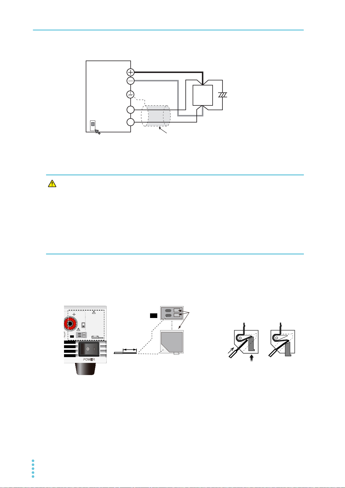
Remote sensing
Use remote sensing when the cable to the load is long.
Remote sensing is a function that stabilizes the output voltage across the load by reducing the influence of
voltage drops and other effects caused by the load cable resistance.
You can use the product remote sensing feature to compensate up to 0.6 V for a single line. Select a load
cable that has sufficient current capacity to prevent the voltage drop in the load cable from exceeding the
compensation voltage.
When you perform remote sensing, keep the output terminal voltage from exceeding the rated output voltage. If you are performing remote sensing with the voltage close to the maximum output voltage, the output is limited by the maximum output voltage (105 % of the rated output voltage). Electrolytic capacitors
may be required at the sensing point (across the load).
To reduce the effect of noise, use twisted-pair cables or 2-core shielded cables. When you use shielded
cables, connect the shield to the product or the load grounding terminal.
PMX_MULTI User’s Manual 23
Page 24
Installation | Sensing Function
+
+
–
–
C
+S
-S
Sensing
switch
OFF
ON
Connect an
electrolytic capacitor
across the load as
necessary.
Output terminal
Chassis terminal
Sensing terminal
PMX
Load
Shielded cable
ON position
WARNING
AWG20-28
STRIP
-
GAUGE
8mm
-
S
+
S
POWER
AWG 20-28
STRIP
-
GAUGE
8mm
DC
OUTPUT
SENSE 4
OFF
ON
-
S
+
S
While pressing here with a screwdriver,
insert the wire at an angle towards the right.
Insert the wire
from this direction.
Pressed down Not pressed down
Example of PMX32-2QU
Connecting the sensing cables
• Never wire the sensing terminals while the POWER switch is turned on.
• For sensing cables, use cables with a voltage rating that is higher than the product’s isolation voltage. Protect the uncovered sections of the shielded cable by
using insulation tubes whose withstand voltage is greater than the product’ isolation voltage.
• Insert the cables so that the wire strands do not touch the chassis when they stick
out of the sensing terminal. Also, insert the cables so that the stripped wires do not
stick out of the terminal.
Be sure to attach the output terminal cover before turning the POWER switch on.
When using the sensing function, connect the sensing cables before connecting the load cables to the output terminals.
If the sensing cables come loose, the output voltage will fluctuate. Because it may increase several tens of
volts higher than the specified value, be sure to set an appropriate OVP trip point.
If you are not going to use remote sensing, return the product to local sensing mode.
Turn the POWER switch off.
1
24 User’s Manual PMX_MULTI
Remove 8 mm of the wire covering. Connect the negative sensing cable to -S that
2
will be used for remote sensing and the positive sensing cable to +S.
Insert the sensing cable towards the right according to the angle of the sensing terminal.
Turn on the SENSE switch on the front panel.
3
Page 25
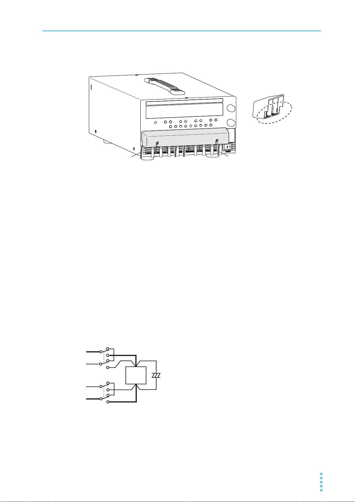
Pull out the sensing wires from the side of or from below the output terminal cover,
Sensing wire
Example of PMX32-2QU
Load
+
–
+
–
–
+
–
4
and attach the output terminal cover.
Sensing wire
This completes the connections.
Electrolytic capacitor to connect across the load
Installation | Sensing Function
If the wiring inductance component is large, the following symptoms may appear.
• Oscillation
If the wires used to connect to the load are long, the wiring inductance and capacitance can cause
phase shifting at a level that cannot be ignored. This may lead to oscillation.
• Output fluctuation
If the load current changes drastically in a pulse-shaped pattern, the output voltage may become large
due to the wiring’s inductance component.
You can reduce the inductance component by twisting the load cables, which stabilizes the voltage. However, if this does not correct the problem, connect an electrolytic capacitor across the load.
Electrolytic capacitor to use
Capacitance: 0.1 µF to several 100 µF
Withstanding voltage: At least 120 % of the rated output voltage of the product
If you are inserting a mechanical switch between the product and the load
S
+S
S
If you want to connect and disconnect the load using a
mechanical switch that is inserted between the product and
the load, be sure to include switches in the sensing cables as
shown in the following figure and turn on and off the load
cable and the sensing cables simultaneously. Before you
C
turn the mechanical switch on or off, be sure to turn off the
OUTPUT key.
PMX_MULTI User’s Manual 25
Page 26
Basic Functions
SELECTOUTPUT
CH1
OUTPUT
ALL
CV
V
s
OFF
CC
A
s
ON
PRLSER
TRACKING 12
LOCK
REMOTE
LAN LAN
DEL AY
DEL AY SET
SET OVP࣭OCP
PRESET A BC
ALARM
%
%
SELECTOUTPUT
CH1
OUTPUT
ALL
CV
V
s
OFF
CC
A
s
ON
PRLSER
TRACKING 12
LOCK
REMOTE
LAN LAN
DEL AY
DEL AY SET
SET OVP࣭OCP
PRESET A BC
ALARM
%
%
SELECTOUTPUT
CH1
OUTPUT
ALL
CV
V
s
OFF
CC
A
s
ON
PRLSER
TRACKING 12
LOCK
REMOTE
LAN LAN
DEL AY
DEL AY SET
SET OVP・OCP
PRESET AB C
ALARM
%
%
OCP
Trip
point
OVP
Trip
point
Panel Display
The voltage and current displays have the following two states.
• Measurement display
• Setting display
In addition to voltage and current, the display area shows the OVP/OCP value, system configuration set-
tings, alarms, output-on delay/ off delay time, tracking, and SCPI communication errors (when CF23 is set
to ON).
Select the channel that you want to configure by pressing the SELECT key. Brackets “[ ]” appear in the display area of the selected channel.
Items that can be set separately for each channel are shown in the display area of each channel, and
items common to all channels or items set to the same value for all channels are shown in the display area
of CH2.
SCPI communication errors are also shown in the display area of CH2 (when CF23 is set to ON).
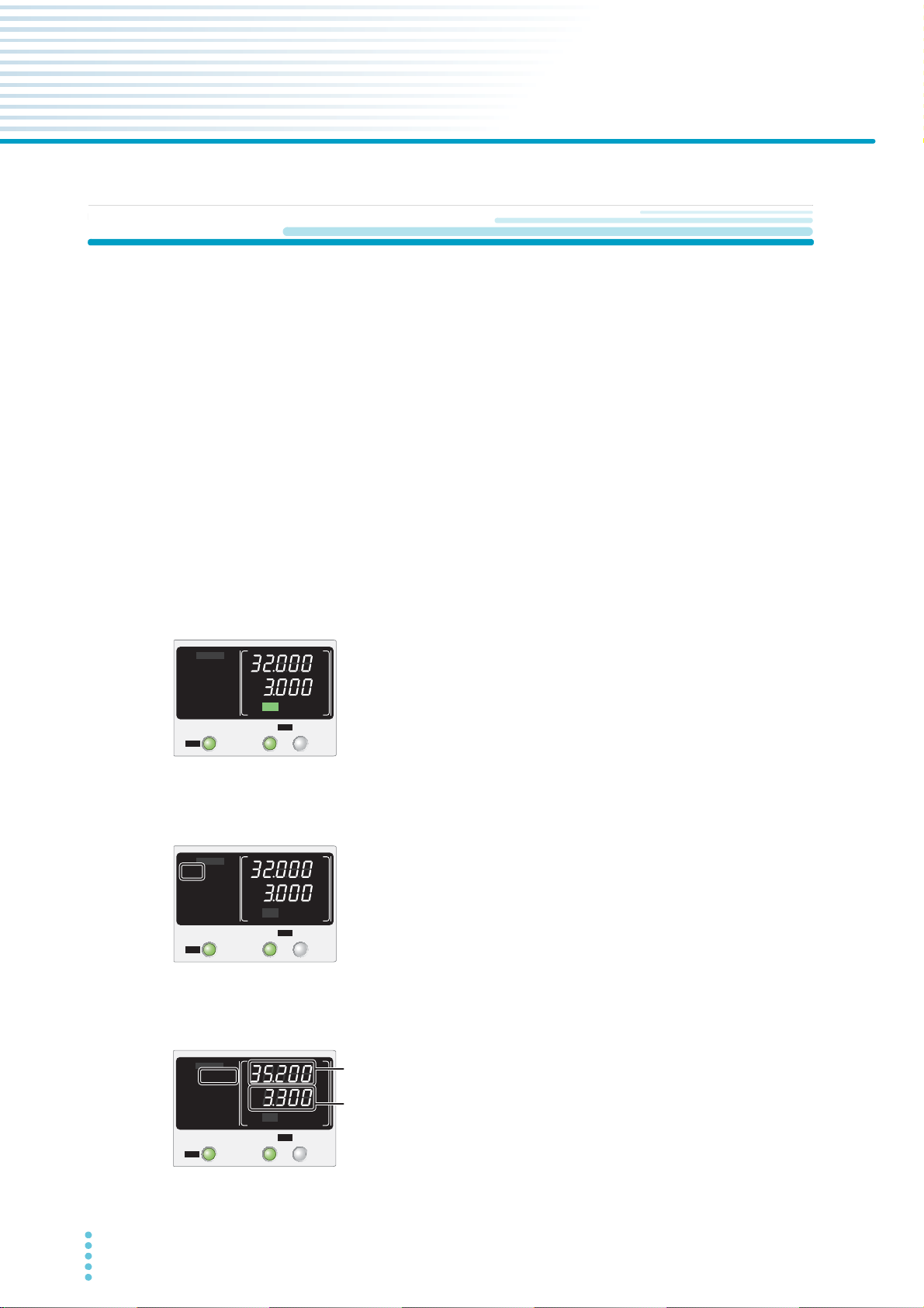
Measurement display
The present output voltage and output current are displayed. The “SET”
indicator in the display area is off. If the outputs of all channels are set off
and you turn the VOLTAGE or CURRENT knob, the “SET” indicator
appears, and the setting display appears.
Setting display
When you press SET, the “SET” indicator appears in the display area, and
the present output voltage and output current settings are displayed.
When you press SET again, the “SET” indicator disappears, and the measurement display appears.
Overvoltage protection and overcurrent protection setting display
When you press OVP•OCP, the “OVP•OCP” indicator appears, and
the present overvoltage protection (OVP) and overcurrent protection
(OCP) settings are displayed.
When you press OVP•OCP again, the “OVP•OCP” indicator disappears, and the measurement display appears.
26 User’s Manual PMX_MULTI
Page 27
System configuration setting display
SELECTOUTPUT
CH1
OUTPUT
ALL
CV
V
s
OFF
CC
A
s
ON
PRLSER
TRACKING 12
LOCK
REMOTE
LAN LAN
DEL AY
DEL AY SET
SET OVP࣭OCP
PRESET A BC
ALARM
%
%
SELECTOUTPUT
CH1
OUTPUT
ALL
CV
V
s
OFF
CC
A
s
ON
PRLSER
TRACKING 12
LOCK
REMOTE
LAN LAN
DEL AY
DEL AY SET
SET OVP࣭OCP
PRESET A BC
ALARM
%
%
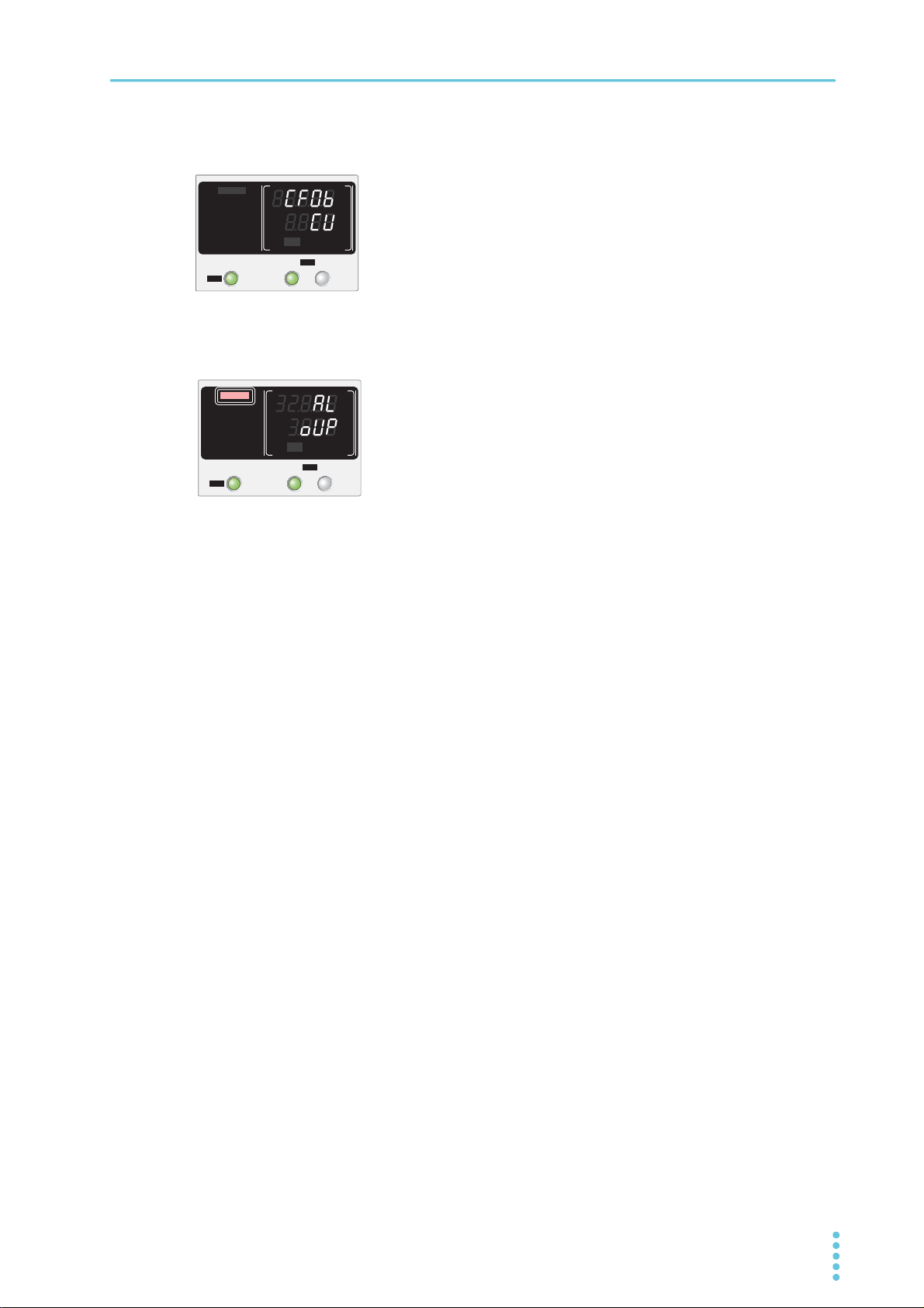
When you press CONFIG, the present system configuration settings are
displayed.
Parameters set to the same value for all channels are shown in CH2. For
items that can be set separately for each channel, the same parameter
number is displayed for all channels.
Alarm display
When an alarm is activated by a protection function, the “ALARM” indicator
(red) and the cause of the alarm are displayed.
Basic Functions | Panel Display
PMX_MULTI User’s Manual 27
Page 28
Basic Functions
FINE
CURRENT
FINE
VOLTAGE
SELECTOUTPUT
CH1
CV
V
s
OFF
CC
A
s
ON
PRLSER
TRACKING 12
%
%
IncreaseDecrease
IncreaseDecrease
Panel Operations
Measurement display, setting display, and OVP/OCP value display
Fine adjustment (FINE)
You can change the resolution of the VOLTAGE and CURRENT knobs. Hold down SHIFT while you turn
the VOLTAGE knob or CURRENT knob to make small changes to the value (FINE mode).
The following table shows the resolutions that can be specified. The specified resolution may not neces-
sarily be applied to the actual output.
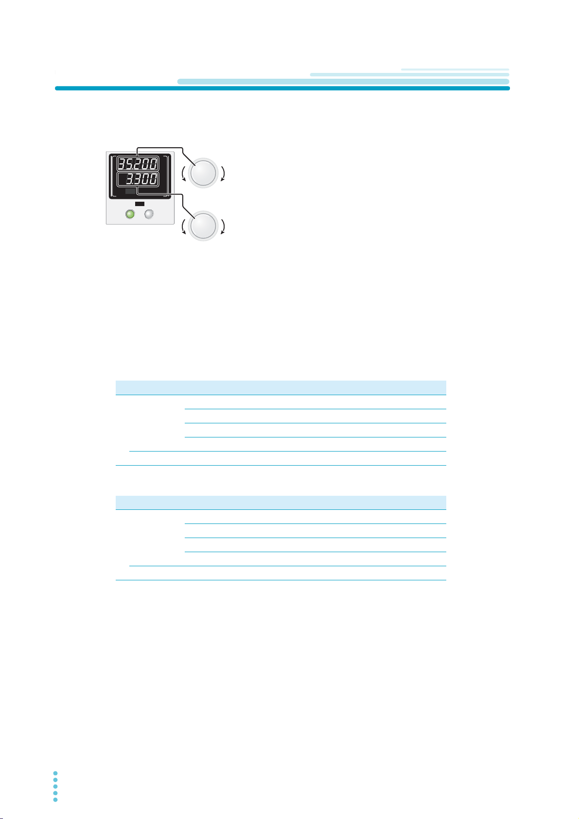
Select the channel that you want to configure by pressing the
SELECT key.
Turn the VOLTAGE knob to change the voltage. Turn the CURRENT knob to change the current.
If the outputs of all channels are set off and you turn the VOLTAGE
or CURRENT knob, the setting display appears, and you can
change the values. When the output is on, you can press SET to
switch to the setting display, and then change the output while you
view the actual voltage or current settings.
• Output voltage setting resolution
PMX32-3DU PMX32-3TR PMX32-2QU
Resolution CH1 100 mV 100 mV 100 mV
CH2 100 mV 100 mV 100 mV
CH3 − 20 mV 100 mV
CH4 − − 100 mV
FINE mode 1mV 1mV 1mV
• Output current setting resolution
PMX32-3DU PMX32-3TR PMX32-2QU
Resolution
CH1
CH2
CH3
CH4
10 mA 10 mA 10 mA
10 mA 10 mA 10 mA
− 20mA 10mA
−−10mA
FINE mode 0.1 mA 0.1 mA 0.1 mA
28 User’s Manual PMX_MULTI
Page 29
Output Operation
SELECTOUTPUT
CH1
CV
V
s
OFF
CC
A
s
ON
PRLSER
TRACKING 12
%
%
CAUTION
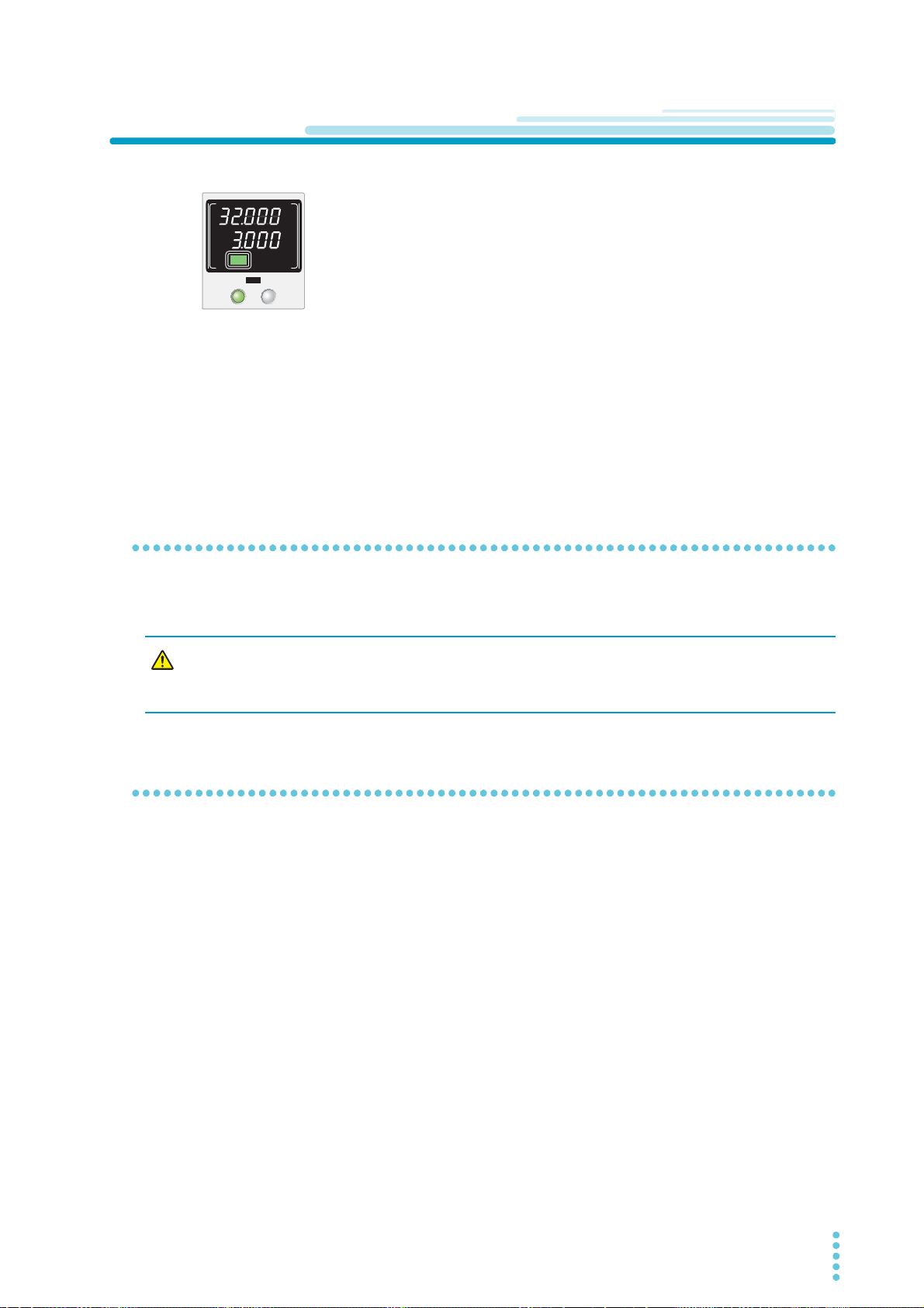
The output turns on and off each time that you press OUTPUT. When the output is
on, the “ON” indicator (green) appears in the display area. When the output is off,
the “OFF” indicator appears.
An OUTPUT key is available for each channel. You can turn on or off the output of
each channel by pressing the OUTPUT key of each channel. You can control the
output of all channels simultaneously using the OUTPUT ALL key. If the output on/
off state of each channel is different, the output of all channels will be turned off
once, and then all the channels will be controlled simultaneously.
When the output is on, output is generated at the present set values.
If you change the settings while the output is on, the changes are applied almost immediately to the output. If the output of all channels is off, the setting display will appear (the “SET” indicator will appear) as
soon as you change a value.
You can set the rise time (speed) that is applied when you change a value. Using CONFIG setting CF07,
select 100 ms (CF07:SLOW) or 10 ms (CF07:FAST) (p.46). (The factory default setting is 100 ms.)
You can use external control to turn the output on and off (p.63).
Basic Functions
Output on/ off setting at power-on
By factory default, the product starts with the output turned off when the power is turned on. Using CON-
FIG setting CF01, you can set the output state at power-on (p.45).
If the output is set so that it is on at power-on, be sure to check the OVP and OCP trip point
settings (p.38 , p.39 ) before you turn off the POWER switch. If the OVP or OCP trip point is
not set properly when the load is changed, the load could be damaged.
Output-on startup state parameter
You can set whether to start in CC mode or CV mode when the output is turned on. Using CONFIG parameter CF06, select prioritize CV (CF06: CV) to start the product as a constant voltage (CV) power supply or
prioritize CC (CF06: CC) to start the product as a constant current (CC) power supply (p.46). (The factory
default setting is prioritize CV.)
PMX_MULTI User’s Manual 29
Page 30
Basic Functions | Output Operation
CH1
CH2
CH3
CH4
204 2046
SET value
Delay time
(s)
On-delay time
Off-delay time
źLVZKHQWKH287387$//NH\LVSUHVVHG
2XWSXWRQ
2XWSXWRII
Hidden
Hidden
Hidden
Shown
Hidden
Shown
Blinking
Blinking
Shown
Shown
Hidden
Shown
Shown
Shown
Shown
DelayDelay
On
Off Off
ON display
OFF display
DELAY display
PMX output
źLVZKHQWKH287387$//NH\LVSUHVVHG
Parameter On-delay
value
Off-delay
value
CH1 0s 4s
CH2 4s 0s
CH3 2s 2s
CH4 2s 6s
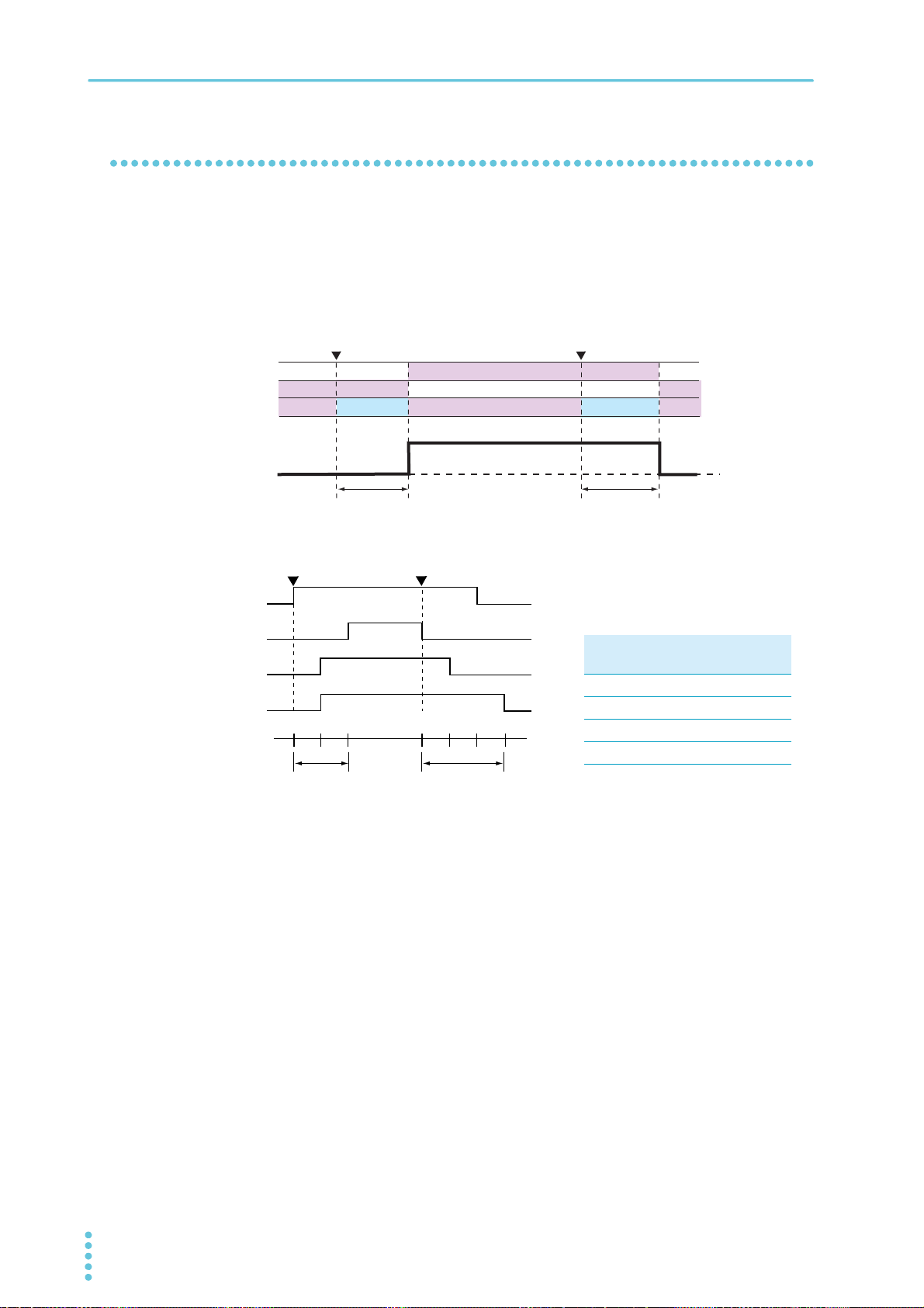
Output-on delay/ off delay
You can set a delay from when the OUTPUT ALL key is pressed to when the output actually turns on or
off. This is a useful function when you want to turn the output on or off by setting a delay according to the
load characteristics.
When set, “DELAY SET” appears in the display area. When in operation, “DELAY” appears.
During the delay time until the output turns on or off, the "DELAY" indicator blinks in the display area.
30 User’s Manual PMX_MULTI
Page 31
Basic Functions | Output Operation
Parameter On-delay
value
Off-delay
value
CH1 0 s 4 s
CH2 4 s 0 s
CH3 2 s 2 s
CH4 2 s 6 s
CH1
CH2
CH3
CH4
204 2046
Delay
Time (s)
On-delay time
Off-delay time
On-delay time
Off-delay time
źLVZKHQWKH287387$//NH\LVSUHVVHG
2XWSXWRQ
2XWSXWRII
3UHVVLQJ'(/$<ZKLOHRXWSXWRQRIILVLQSURJUHVV
FOHDUVWKHGHOD\IXQFWLRQDQGWXUQVWKHRXWSXWRII
CH1
CH2
CH3
CH4
204 2046
Delay
Time (s)
2XWSXWRQ
'HOD\IXQFWLRQ
&OHDU
2XWSXWRII
LVZKHQWKH'(/$<NH\LVSUHVVHG
Example of PMX32-2QU
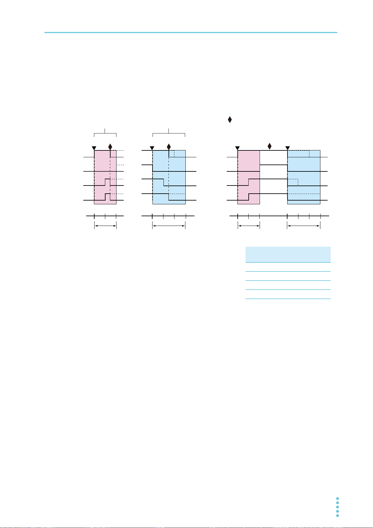
If you press DELAY while the “DELAY” indicator is blinking, the output-on delay/ off delay operation is canceled, and the output of all channels is turned off. If you want to resume the output-on delay/ off delay
operation, press DELAY (the “DELAY” indicator appears).
If you press DELAY when the output of all channels is on after an output-on delay operation, the delay
function will be cleared. If you press OUTPUT ALL in this condition, the output of all channels is turned off
without an off-delay operation.
The actual rise time at output-on and the fall time at output-off very depending on the output and load conditions. The timing charts above ignore the rise and fall times.
Because there is time for internal processing from when OUTPUT ALL is pressed until the output actually
turns on or off, even if you set the delay time 0 s, there will be an error in the order of tens of milliseconds.
PMX_MULTI User’s Manual 31
Page 32
Basic Functions | Output Operation
SELECTOUTPUT
CH1
OUTPUT
ALL
CV
V
s
OFF
CC
A
s
ON
PRLSER
TRACKING 12
LOCK
REMOTE
LAN LAN
DEL AY
DEL AY SET
SET OVP࣭OCP
PRESET A BC
ALARM
%
%
Output on
Delay
Output off
Delay
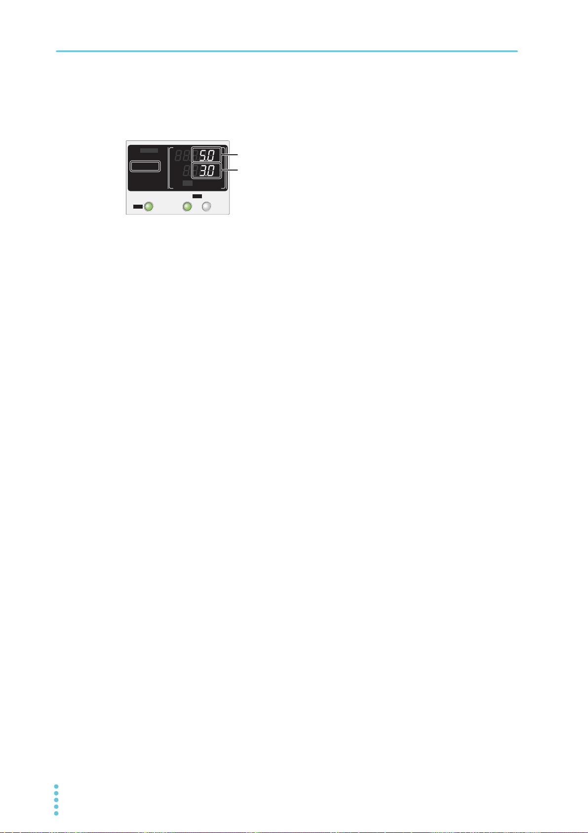
Indication of the output-on delay/ off delay time
Setting the output-on delay/ off delay time
If the external control for turning the output on or off in the CONFIG settings is set to on (CF04:ON), the
delay function cannot be used. Set the external control for turning output on and off to off (CF04: OFF).
Press OUTPUT ALL to turn off the output.
1
The output of all channels is turned off.
Press DELAY SET (SHIFT+DELAY).
2
“DELAY SET” appears in the display area.
Press SELECT to select the channel you want to configure.
3
The selected channel is indicated with brackets.
Set the output-on delay time using the VOLTAGE knob and the output-off delay
4
time using the CURRENT knob.
Delay time setting range 0.1 s to 99.9 s
Resolution 1 s, fine mode: 0.1 s
The voltmeter shows the output-on delay time and the ammeter the output-off delay time.
To set other channels, repeat steps step 3 and step 4.
5
To exit from the delay time setting, press DELAY SET (SHIFT+DELAY), LOCK, or
6
SET.
The “DELAY SET” indicator disappears. If you pressed DELAY SET (SHIFT+DELAY) or LOCK, the
measurement display appears. If you pressed SET, the setting display appears.
This completes the setting.
32 User’s Manual PMX_MULTI
Page 33

Basic Functions | Output Operation
Activating the output-on delay/ off delay
Only the OUTPUT ALL key can be used to control the output-on delay/ off delay. output-on delay/ off delay
will not be activated using the OUTPUT key of each channel.
The output of channels that do not have a delay time set will also be turned on or off simultaneously.
Press DELAY.
1
“DELAY” appears in the display area.
To activate the output-on delay, press OUTPUT ALL to turn the output on.
2
When the output-on delay is activated, “DELAY” blinks in the display area. When all channels turn
on, “DELAY” changes from blinking to solid.
To activate the output-off delay, press OUTPUT ALL again to turn the output off.
3
When the output-off delay is activated, “DELAY” blinks in the display area. When all channels turn
off, “DELAY” changes from blinking to solid.
To clear the delay function, press DELAY.
4
The “DELAY” indicator will disappear from the display area.
PMX_MULTI User’s Manual 33
Page 34
Basic Functions
Output voltage Vout
Crossover point
A
= CV mode area
B
= CC mode area
Vs = Set voltage
Is = Set current
Rc = Vs/Is (Ohmʼs Law)
RL = Load resistance
Vmax = Maximum settable voltage
Imax = Maximum settable current
L
RL<Rc
Vmax
Vs
ImaxIs
0
p
q
A
B
A
B
A
B
CV Power Supply and CC Power Supply
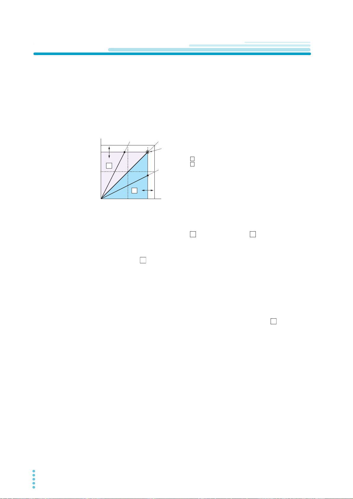
The PMX has functions that makes it possible to function as a constant-voltage source and constant-current source even when the load is changed. The constant-voltage source operation is referred to as constant-voltage (CV) mode. The constant-current source operation is referred to as constant-current (CC)
mode. The operation mode is determined by the following three values.
• Output voltage setting (Vs)
• Output current setting (Is)
• Load resistance (R
The operation modes are described below.
L)
R
>Rc
RL=Rc
Output current Iout
The above figure shows the product’s operation modes. The load resistance is denoted as R
L. The resis-
tance, which is denoted as Rc, is calculated from the set voltage and current (Rc = Vs/Is). The power sup-
ply is designed so that it operates in CV mode in area and CC mode in area . The boundary is the
line defined by R
L = Rc. This line represents the load at which the output voltage and the set voltage are
equal and the output current and the set current are equal. If load resistance RL is greater than resistance
Rc, the operating point is in area , and the PMX operates in CV mode (point p). In this case, the set cur-
rent Is equals the current limit.
When the product is operating in CV mode, the output voltage is maintained at the set voltage. Output current I is determined by the equation I = Vs/RL and is a current that is less than current limit Is. The actual
current that flows is not necessarily equal to the specified value.
For loads in which transient overcurrent flows, current limit Is must be set higher than the overcurrent
value.
Conversely, if load resistance R
L is less than resistance Rc, the operating point is in area , and the prod-
uct operates in CC mode (point q). In this case, set voltage Vs equals the voltage limit.
When the product is operating in CC mode, the output current is maintained at the set current. Output voltage V is determined by the equation V = Is x R
L and is a voltage that is less than voltage limit Vs. The
actual voltage that is applied is not necessarily equal to the specified value.
For loads that generate transient overvoltage, voltage limit Vs must be set higher than the over.
Crossover point
The product switches automatically between CV mode and CC mode according to the changes in the
load. A crossover point is the point at which the mode switches.
For example, when operating in CV mode, if the load changes and the output current reaches the current
limit, the PMX automatically switches to CC mode to protect the load. Likewise, when operating in CC
mode, if the output voltage reaches the voltage limit, the PMX switches to CV mode.
34 User’s Manual PMX_MULTI
Page 35

Basic Functions | CV Power Supply and CC Power Supply
CV mode and CC mode operation example
This section uses a power supply with a rated output voltage of 100 V and a rated output current of 10 A as
an example.
A load resistance (R
and output current are set to 30 V and 5 A, respectively. In this case, Rc = 30 V/5 A = 6 Ω. Because 8 Ω is
greater than 6 Ω (R
age in CV mode, you can increase the voltage up to the voltage defined by the following equation: Vs = Is
L. Substituting the values, we obtain Vs = 5 A × 8 Ω = 40 V. If you try to increase the voltage above this
× R
point, the crossover point is reached, and the power supply automatically switches to CC mode. To maintain operations in CV mode, increase the current limit.
Next, a load resistance (RL) of 5 Ω is connected to the output terminals of the power supply. The output
voltage and output current are set to 30 V and 5 A, respectively. In this case, Rc = 30 V/5 A = 6 Ω.
Because 5 Ω is less than 6 Ω (RL < Rc), the power supply operates in CC mode. If you want to increase
the current in CC mode, you can increase the current up to the current defined by the following equation:
Is = Vs/R
L. Substituting the values, we obtain Is = 30 V/5Ω = 6 A. If you try to increase the current above
this point, the crossover point is reached, and the power supply automatically switches to CV mode. To
maintain operations in CC mode, increase the voltage limit.
L) of 8 Ω is connected to the output terminals of the power supply. The output voltage
L > Rc), the power supply operates in CV mode. When you want to increase the volt-
PMX_MULTI User’s Manual 35
Page 36

Basic Functions
Using the PMX as a CV or CC Power Supply
When the PMX is used as a constant-voltage power supply, the set current is the limit to the current that
can flow through the load.
When the PMX is used as a constant-current power supply, the set voltage is the limit to the voltage that
can be applied to the load.
If the specified limit is reached, the PMX automatically switches its operation mode. When the PMX
switches its operation mode, the “CV” (green) and “CC” (red) indications in the display area change.
Press SET to change to the setting display.
1
“SET” appears in the display area.
Press SELECT to select the channel you want to configure.
2
The selected channel is indicated with bracketsed.
Turn the VOLTAGE knob to set the voltage.
3
Voltage setting range: 0 % to 105 % of the rated output voltage of each channel
CH1 CH2 CH3 CH4
PMX32-3DU 0 V to 33.6 V 0 V to 33.6 V − −
PMX32-3TR 0 V to 33.6 V 0 V to 33.6 V 0 V to 6.3 V −
PMX32-2QU 0 V to 33.6 V 0 V to 33.6 V 0 V to 18.9 V 0 V to 18.9 V
Turn the CURRENT knob to set the current.
4
Current setting range: 0 % to 105 % of the rated output voltage of each channel
CH1 CH2 CH3 CH4
PMX32-3DU 0 A to 3.15 A 0 A to 3.15 A − −
PMX32-3TR 0 A to 3.15 A 0 A to 3.15 A 0 A to 5.25 A −
PMX32-2QU 0 A to 2.1 A 0 A to 2.1 A 0 A to 2.625 A 0 A to 2.625 A
To set other channels, repeat steps step 2 to step 4.
5
Press OUTPUT to turn output on.
6
“SET” disappears from the display area, and “ON” appears. When the PMX is operating as a constant-voltage power supply, “CV” (green) is displayed. When the PMX is operating as a constantcurrent power supply, “CC” (red) is displayed.
This completes the setting.
Even when the output is on, you can set the voltage and current by carrying out step 3 and step 4 while
checking the actual output voltage or current (p.26).
You can use the CONFIG settings to set the output-on startup state (CF06: CC/ CV) (p.46).
Set this according to the operation mode that you are using. You can prevent overshoot from occurring
when the output is turned on by prioritizing CV when using the PMX as a constant-voltage power supply
and by prioritizing CC when using the PMX as a constant-current power supply.
When the output is turned on, the internal capacitors are charged. Depending on the set current, the PMX
may enter CC mode for an instant.
36 User’s Manual PMX_MULTI
Page 37

Protection Functions and Alarms
Maximum voltage: 30 V
Maximum current: 8 mA
12
13
CONTROL TERMINAL
ALM STATUS
STATUS COM
PMX
This product is equipped with the following protection functions.
• Overvoltage protection (OVP) (p.38) • Overcurrent protection (OCP) (p.39)
• Overheat protection (OHP) (p.41) • Communication monitoring (WATCHDOG) (p.41)
• Alarm input (ALARM IN) (p.41)
Alarm occurrence and clearing alarms
Alarm occurrence
When the output is shut off by a protection function, an alarm occurs, and the PMX is set to the following
state.
• The output is turned off.
You can use the CONFIG settings to set the output state (CF08) for when OVP/OCP is activated
(p.47).
Basic Functions
• The display area shows “ALARM” (red), the voltmeter shows “AL”, and the ammeter shows the cause
of the alarm.
When a CONFIG parameter is displayed, the cause of alarm is not displayed.
• An alarm signal is output.
When an alarm occurs, an alarm signal is output from pin 12 of the CONTROL TERMINAL.
Clearing alarms
Press ALM CLR (SHIFT + SET) or turn off the POWER switch. Fix the problem that caused the alarm, and
turn the POWER switch back on. When clearing an alarm with an alarm input (ALARM IN), turn the
POWER switch off once and then back on.
If you do not resolve the cause of the alarm, an alarm will occur again.
If an alarm still occurs even after you have resolved all the causes of alarms, the product may be malfunc-
tioning. Stop using it immediately, and contact your Kikusui agent or distributor.
Alarm signal
The output terminal is isolated from other terminals through an open collector photocoupler. The output-on
signals of CH1 to CH4 and the power-on signal share a common ground.
PMX_MULTI User’s Manual 37
Page 38
Basic Functions | Protection Functions and Alarms
SELECTOUTPUT
CH1
OUTPUT
ALL
CV
V
s
OFF
CC
A
s
ON
PRLSER
TRACKING 12
LOCK
REMOTE
LAN LAN
DEL AY
DEL AY SET
SET OVP࣭OCP
PRESET A BC
ALARM
%
%
OVP
Trip point
OVP trip point indication
Setting and displaying the protection functions
Overvoltage protection (OVP)
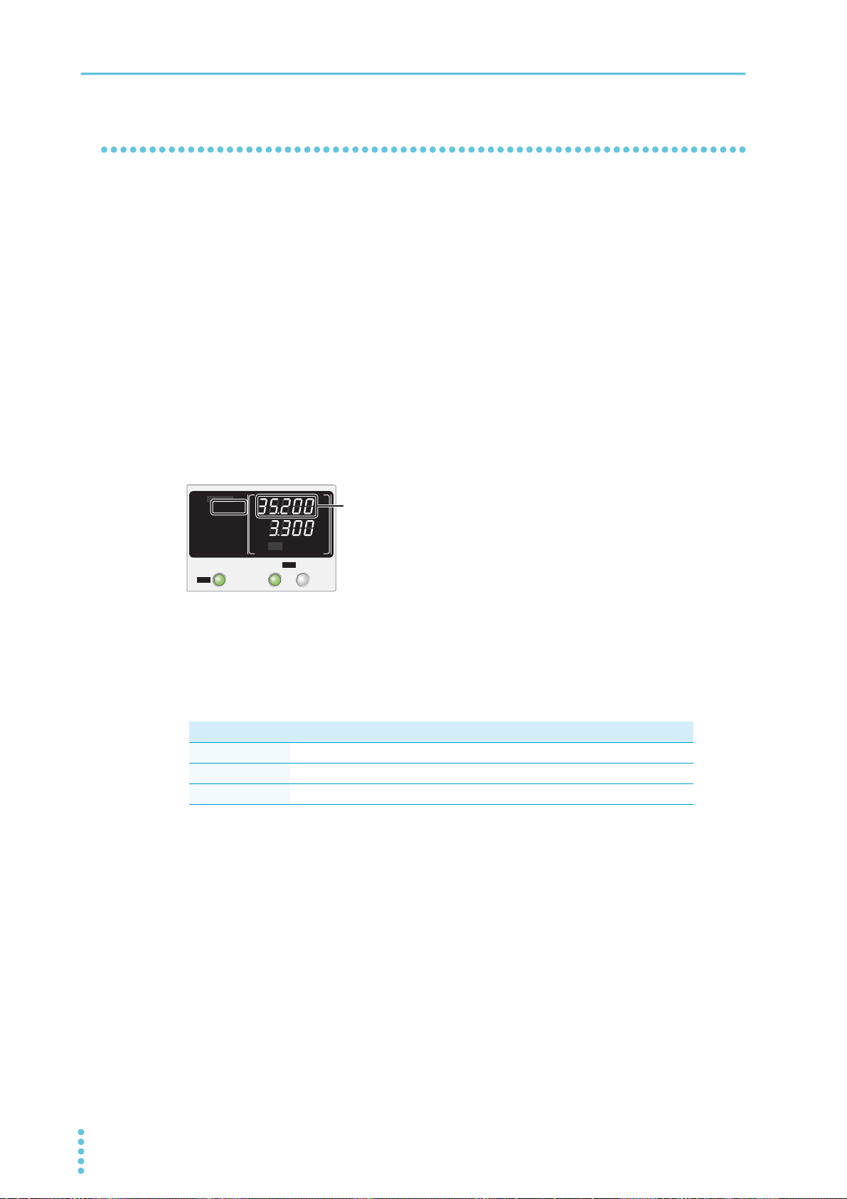
Overvoltage protection (OVP) is activated when the output terminal voltage exceeds the set voltage (OVP
trip point).
Immediately after you purchase the PMX or immediately after a load is changed, set the OVP trip point to
a value that is appropriate for the load.
Setting the OVP trip point
OVP operates on the output terminal voltage. If you want to activate the protection feature according to the
voltage across the load, take the voltage drop in the load cable into consideration when you set the OVP
trip point.
Press OVP•OCP.
1
The display area shows “OVP•OCP”, and the voltmeter displays the present OVP trip point.
Press SELECT to select the channel you want to configure.
2
The selected channel is indicated with brackets.
Turn the VOLTAGE knob to set the OVP trip point.
3
OVP setting range: 10 % to 110 % of the rated output voltage
CH1 CH2 CH3 CH4
PMX32-3DU 3.2 V to 35.2 V 3.2 V to 35.2 V − −
PMX32-3TR 3.2 V to 35.2 V 3.2 V to 35.2 V 0.6 V to 6.6 V −
PMX32-2QU 3.2 V to 35.2 V 3.2 V to 35.2 V 1.8 V to 19.8 V 1.8 V to 19.8 V
To set other channels, repeat steps step 2 and step 3.
4
Press OVP•OCP, LOCK, or SET to finish the configuration.
5
The OVP trip point will be set. The “OVP•OCP” indicator will disappear from the display area.
If you pressed OVP•OCP or LOCK, the measurement display appears. If you pressed SET, the setting display appears.
This completes the setting.
38 User’s Manual PMX_MULTI
Page 39
Basic Functions | Protection Functions and Alarms
Alarm indication when OVP is activated
SELECTOUTPUT
CH1
OUTPUT
ALL
CV
V
s
OFF
CC
A
s
ON
PRLSER
TRACKING 12
LOCK
REMOTE
LAN LAN
DEL AY
DEL AY SET
SET OVP࣭OCP
PRESET A BC
ALARM
%
%
OCP trip point indication
SELECTOUTPUT
CH1
OUTPUT
ALL
CV
V
s
OFF
CC
A
s
ON
PRLSER
TRACKING 12
LOCK
REMOTE
LAN LAN
DEL AY
DEL AY SET
SET OVP࣭OCP
PRESET A BC
ALARM
%
%
OCP
Trip point
Checking the OVP operation
Check that “ON” (green) is not shown in the display area.
1
Set the output voltage to a value lower than the OVP trip point.
2
Press OUTPUT to turn output on.
3
“ON” (green) appears in the display area.
Slowly turn the VOLTAGE knob clockwise until the OVP is activated.
4
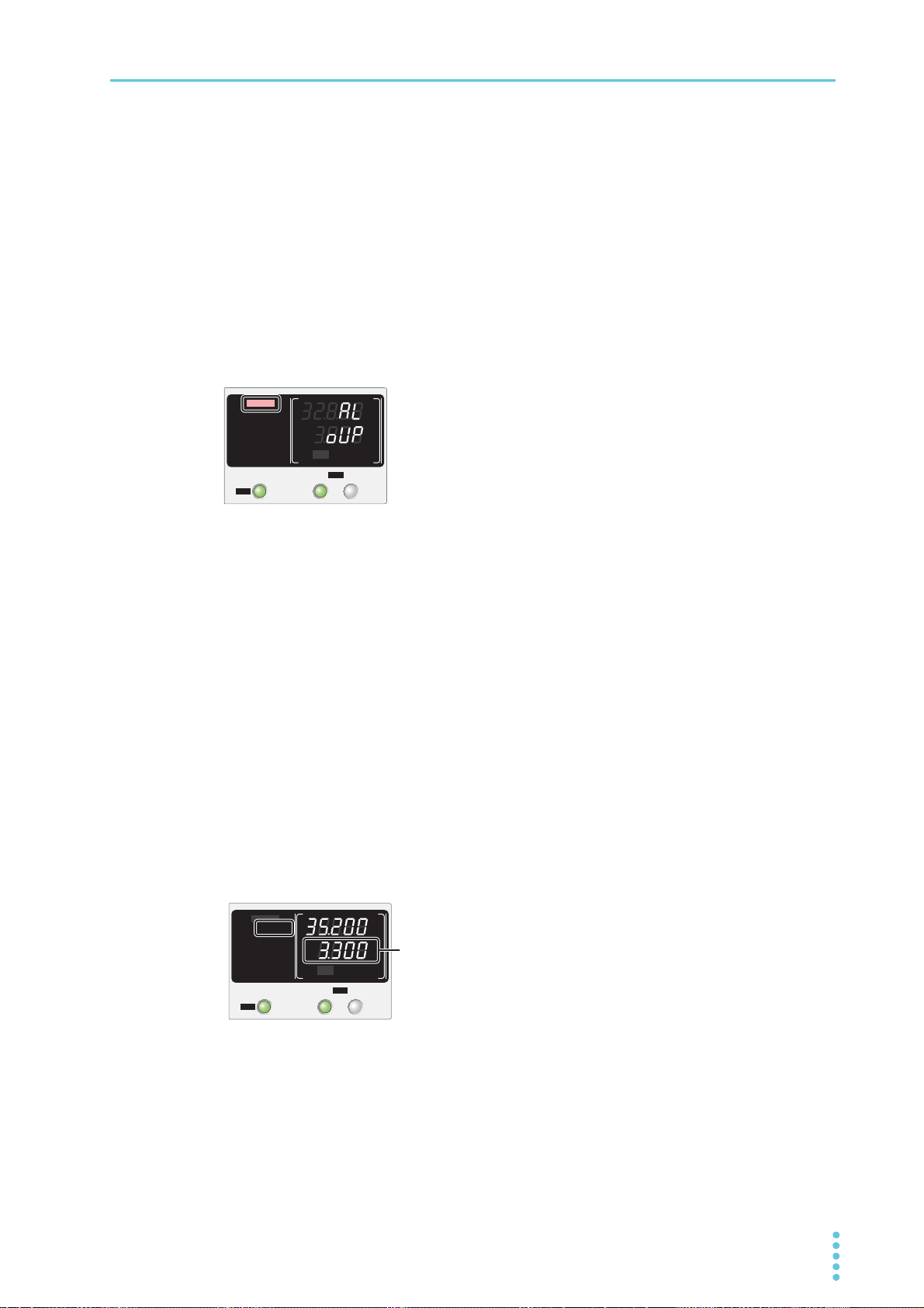
When the output voltage exceeds the OVP trip point, an alarm will occur. “ALARM” (red) is displayed to indicate that OVP has been activated.
Check that output has turned off.
5
Press ALM CLR (SHIFT + SET) to clear the alarm.
6
If you do not change the output voltage and turn the output on, OVP will be activated again.
Overcurrent protection (OCP)
Overcurrent protection (OCP) is activated when the output current exceeds the set current (OCP trip
point).
Immediately after you purchase the product or immediately after a load is changed, set the OCP trip point
to a value that is appropriate for the load.
Setting the OCP trip point
Press OVP•OCP.
1
The display area shows “OVP•OCP”, and the ammeter displays the present OCP trip point.
Press SELECT to select the channel you want to configure.
2
The selected channel is indicated with brackets.
PMX_MULTI User’s Manual 39
Page 40
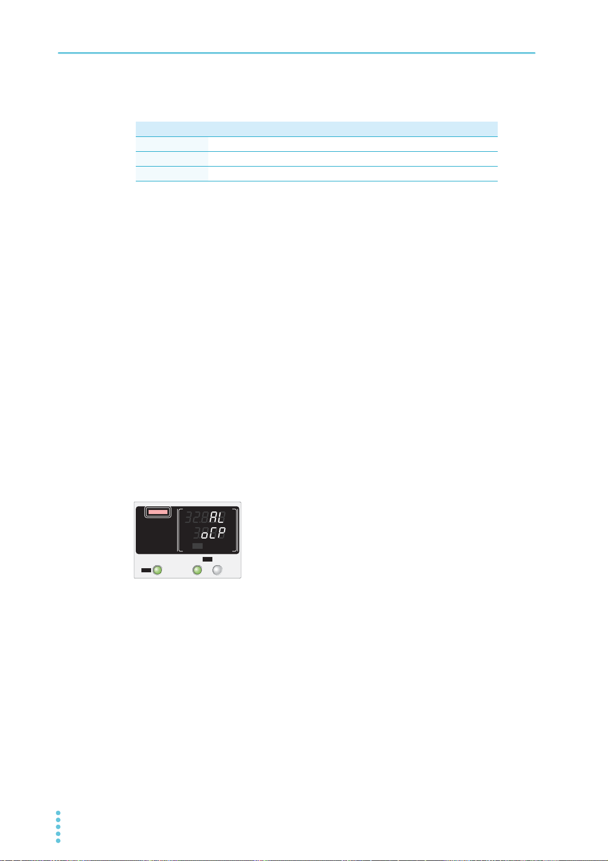
Basic Functions | Protection Functions and Alarms
Alarm indication when OCP is activated
SELECTOUTPUT
CH1
OUTPUT
ALL
CV
V
s
OFF
CC
A
s
ON
PRLSER
TRACKING 12
LOCK
REMOTE
LAN LAN
DEL AY
DEL AY SET
SET OVP࣭OCP
PRESET A BC
ALARM
%
%
Turn the CURRENT knob to set the OCP trip point.
3
OCP setting range: 10 % to 110 % of the rated output current
CH1 CH2 CH3 CH4
PMX32-3DU 0.3 A to 3.3 A 0.3 A to 3.3 A − −
PMX32-3TR 0.3 A to 3.3 A 0.3 A to 3.3 A 0.5 V to 5.5 V −
PMX32-2QU 0.2 A to 2.2 A 0.2 A to 2.2 A 0.25 A to 2.75 A 0.25 A to 2.75 A
To set other channels, repeat steps step 2 to step 4.
4
Press OVP•OCP, LOCK, or SET to finish the configuration.
5
The OCP trip point will be set. The “OVP•OCP” indicator will disappear from the display area.
If you pressed OVP•OCP or LOCK, the measurement display appears. If you pressed SET, the setting display appears.
This completes the setting.
Checking the OCP operation
To check the OCP operation, short the output terminals of the channel you want to check.
Check that “ON” (green) is not shown in the display area.
1
Set the output current to a value lower than the OCP trip point.
2
Press OUTPUT to turn output on.
3
“ON” (green) appears in the display area.
Slowly turn the CURRENT knob clockwise until the OCP is activated.
4
When the output current exceeds the OCP trip point, an alarm will occur. “ALARM” (red) appears in
the display area to indicate that OCP has been activated.
Check that output has turned off.
5
Press ALM CLR (SHIFT + SET) to clear the alarm.
6
If you do not change the output current and turn the output on, OCP will be activated again.
40 User’s Manual PMX_MULTI
Page 41
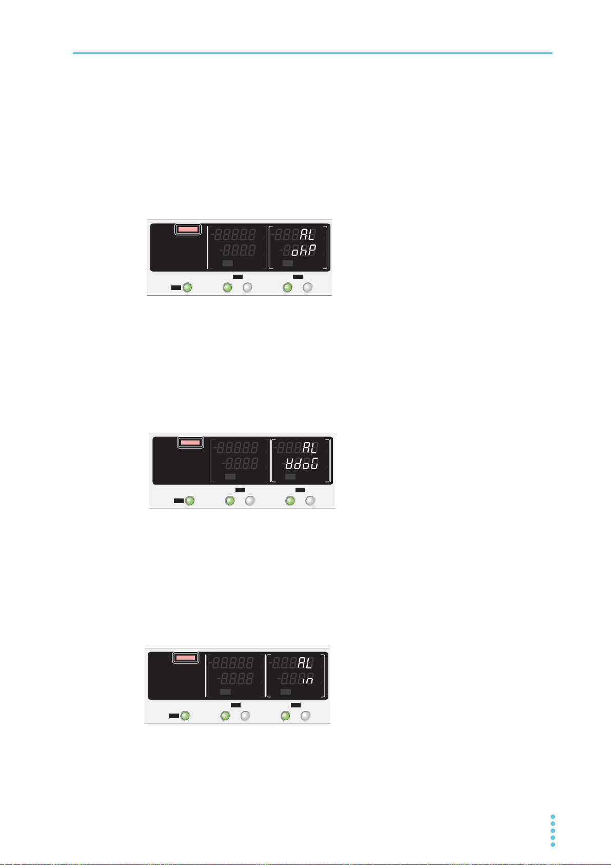
Basic Functions | Protection Functions and Alarms
Alarm indication when OHP is activated
SELECTOUTPUT
CH1
SELECTOUTPUT
CH2
OUTPUT
ALL
CV
V
s
OFF
CC
A
s
ON
PRLSER
TRACKING 12
LOCK
REMOTE
LAN LAN
DEL AY
DEL AY SET
SET OVP࣭OCP
PRESET A BC
ALARM
CV
V
s
OFF
CC
A
s
ON
PRLSER
TRACKING 12
%%
%%
Alarm indication when WATCHDOG is activated
SELECTOUTPUT
CH1
SELECTOUTPUT
CH2
OUTPUT
ALL
CV
V
s
OFF
CC
A
s
ON
PRLSER
TRACKING 12
LOCK
REMOTE
LAN LAN
DEL AY
DEL AY SET
SET OVP࣭OCP
PRESET A BC
ALARM
CV
V
s
OFF
CC
A
s
ON
PRLSER
TRACKING 12
%%
%%
Alarm indication when ALARM IN is activated
SELECTOUTPUT
CH1
SELECTOUTPUT
CH2
OUTPUT
ALL
CV
V
s
OFF
CC
A
s
ON
PRLSER
TRACKING 12
LOCK
REMOTE
LAN LAN
DEL AY
DEL AY SET
SET OVP࣭OCP
PRESET A BC
ALARM
CV
V
s
OFF
CC
A
s
ON
PRLSER
TRACKING 12
%%
%%
Overheat protection (OHP)
Overheat protection (OHP) is activated when the product’s internal temperature rises to an abnormal level.
• When the product is used in an environment that exceeds its operating ambient temperature range
(0 °C to +40 °C).
• When the product is used with its air inlet or outlet port blocked.
• When the fan motor has stopped.
If you do not fix the problem that caused the overheat protection to be activated, OHP will be activated
again even if you turn the POWER switch off and on.
Communication monitoring (WATCHDOG)
The watchdog function monitors the SCPI command communication status.
Communication is assumed to have stopped if there is no communication within the time period specified
by the communication monitoring timer setting (CF24).
The function operates regardless of whether the product is in remote or local (panel control) mode. If you
are not using remote control (commands), set communication monitoring off using a timer setting.
In the alarm state, turn off communication monitoring before clearing the alarm.
Alarm input (ALARM IN)
The output of all channels is turned off when the PMX receives an alarm signal (0.5 V or less, or shorted
with pin 13) through pin 12 of the J1 connector when an abnormal condition occurs.
To apply an alarm signal, short the contact switch for at least 0.5 s. If the time is too short, the alarm may
not be detected.
Even when the POWER switch is turned off and then turned back on, if an alarm signal is being received,
ALARM IN will be activated again.
PMX_MULTI User’s Manual 41
Page 42

Basic Functions
CONFIG Settings
Use the CONFIG settings to perform system configuration of the product. You can set and display the following parameters in the CONFIG settings.
Effect: ● indicates that the parameter is affected when the panel settings are reset (CF00).
■ indicates that the parameter may be affected when the LAN interface settings are reset (CF40: LCI/
DEF/APPL).
Note: “A” indicates that the parameter is applied when the PMX exits from CONFIG settings.
“B” indicates that the parameter is applied when the power is turned on. “C” indicates that the parameter
is applied after CF40 is executed.
Display
switching
System CF00 − Reset Panel setting reset − A
Interface CF20 LAN LAN LAN interface
*3
LAN
USB
RS232C CF51 BAUD Baud rate RS232C baud rate − B
Firmware
*1. Can be set separately for each channel
*2. This parameter is affected only when the LAN interface settings are reset (CF40: LCI/ DEF/ APPL).
*3. For details on the LAN interface settings, see the “Communication Interface Manual” on the included CD-ROM.
*4. The vendor ID is shown in CH1 and the product ID in CH2.
*5. The firmware version is shown in CH1 and the build number in CH2.
Parameter
number
CF01 PON Power on Output state at power-on − B
CF02 MEM Memory Memory content display − A
CF03 LOC Lock Key lock content − A
CF04
CF05
CF06
CF07
CF08 A.OFF Alarm off Output state when a protection function (OVP/OCP) is
CF09
CF21 USB USB USB interface − B
CF22 232 RS232C RS232C interface − B
CF23 TRAC Trace SCPI communication error display − A
CF24 WDOG Watchdog Communication monitoring (watchdog) timer − A
CF25 BEEP Beep Buzzer on/off − A
CF30 IP1 Ip addr. 1 IP address display (1) − −
CF31 IP2 Ip addr. 2 IP address display (2) − −
CF32 IP3 Ip addr. 3 IP address display (3) − −
CF33 IP4 Ip addr. 4 IP address display (4) − −
CF34 HA1 HW. addr. 1, 2 MAC address display (1) and (2) − −
CF35 HA2 HW. addr. 3, 4 MAC address display (3) and (4) − −
CF36 HA3 HW. addr. 5, 6 MAC address display (5) and (6) − −
CF40 BOOT LAN Reboot LAN setting reset (LCI/DEF)/apply (APPL) − A
CF41 ADR Address config IP address assignment method
CF42 S.IP1 Static IP 1 Manual IP address setting (1)
CF43 S.IP2 Static IP 2 Manual IP address setting (2)
CF44 S.IP3 Static IP 3 Manual IP address setting (3)
CF45 S.IP4 Static IP 4 Manual IP address setting (4)
CF46 SUB Subnet Mask IP address subnet mask ■ B/C
CF50
CF60
Mnemonic Setting/ display Effect Note
*1
E.OUT Ext. on/ off External control for turning output on/off ● A
*1
E.LOG Ext. logic External control logic for turning output on/off −A
*1
PRIO Priority Output-on startup state − A
*1
RIS.T Rise Time Rise time when a value is changed − A
activated
*1
DTRC Dual tracking Tracking operation − A
*4
VID V. ID Vendor ID (VID) display − −
PID P. ID Product ID (PID) display − −
*5
VER Version Firmware version display − −
B.NO Bild no. Build number display − −
−A
■
■
■
■
■
■
*2
B
B/C
B/C
B/C
B/C
B/C
42 User’s Manual PMX_MULTI
Page 43
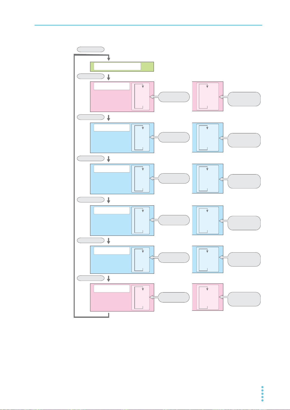
CONFIG key
CONFIG key
CONFIG key
CONFIG key
CONFIG key
CONFIG key
CONFIG key
Measured value display
System
Interface
LAN
LAN
USB•RS232C
Firmware
...
CF00
CF02
CF09
PON
DTRC
...
LAN
USB
BEEP
...
VID/PID
BAUD
...
CF20
CF21
CF25
CF50
CF51
Mnemonic display
VOLTAGE knob
+
LOCAL key
VOLTAGE knob
+
LOCAL key
VOLTAGE knob
+
LOCAL key
VOLTAGE knob
VOLTAGE knob
VOLTAGE knob
IP1
IP2
SUB
...
...
CF30
CF31
CF36
VOLTAGE knob
+
LOCAL key
VOLTAGE knob
BOOT
ADR
SUB
...
...
CF40
CF41
CF46
VOLTAGE knob
+
LOCAL key
VOLTAGE knob
VER/B..NO
CF60
VOLTAGE knob
+
LOCAL key
VOLTAGE knob
Basic Functions | CONFIG Settings
PMX_MULTI User’s Manual 43
Page 44
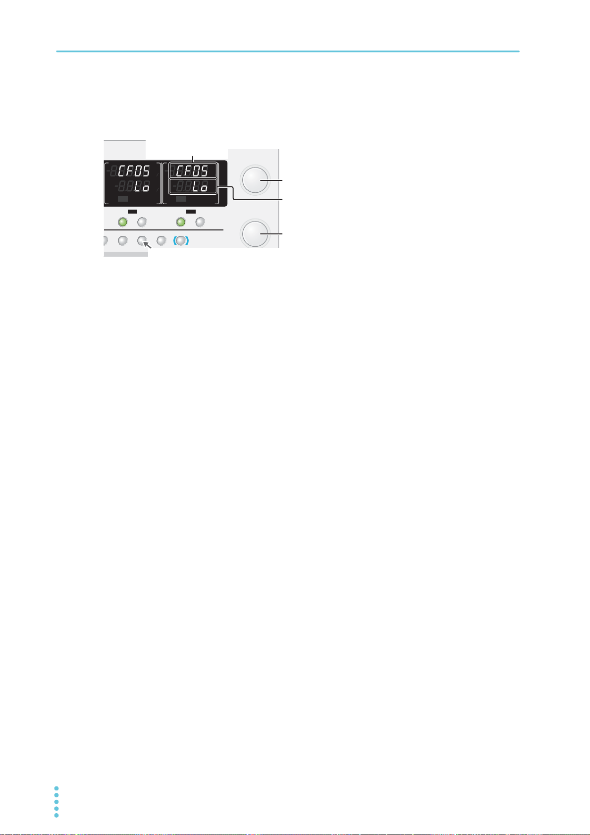
Basic Functions | CONFIG Settings
CBACLR
OVP࣭OCP
TLOCKCONFIG
SELECTOUTPUT
CH3
SELECTOUTPUT
CH4
FINE
CURRENT
FINE
VOLTAGE
LOCAL
SHIFT
CV
V
s
OFF
CC
A
s
ON
PRLSER
TRACKING 12
CV
V
s
OFF
CC
A
s
ON
PRLSER
TRACKING 12
%%
%%
Setting display
VOLTAGE knob
Select the parameter number.
CURRENT knob
Select the value or the
parameter to display.
CONFIG key Select the parameter number.
Parameter number CF (CONFIG) + a two-digit number
or a mnemonic display
CONFIG setting and display examples
(Example of PMX32-2QU)
Displaying and setting CONFIG parameters
CF00 and CF40 are execution parameters of functions. For the execution procedure, see the details of
each CONFIG parameter.
Use the CONFIG key and the VOLTAGE knob to select the CONFIG parameter you
1
want to set.
The voltmeter displays the parameter number. The ammeter displays the corresponding setting.
Parameters that can be set separately for each channel are displayed on all channels.
Parameters that are set to the same value on all channels are displayed only in the CH2 display
area.
Each time you press CONFIG, the parameter number changes in the following order:
CF00→CF20→CF30→CF40→CF50→CF60→measurement display. Turning the VOLTAGE knob
changes the ones digit.
Pressing LOCAL changes the parameter number to the mnemonic display. Turning the VOLTAGE
knob while holding down the LOCAL key switches the CONFIG parameter while retaining the mnemonic display.
Turn the CURRENT knob to change the value of the parameter.
2
To specify or display other parameters, repeat step 1 and step 2.
3
Hold down CONFIG until the measurement display appears or press SET to exit
4
from CONFIG settings.
There are parameters whose values are applied immediately, those whose values are applied after
the power is turned off and then back on, and those whose values are applied when [APPL] is
executed using CF40 (p.42).
This completes the setting.
44 User’s Manual PMX_MULTI
Page 45
CONFIG parameter details
The details of CONFIG parameters are provided below.
CF00 (RST) Panel setting reset
Select this to set the following parameters to their factory default settings (p.96). Then, press SET twice to
execute the reset.
• Output voltage • Output current
• Overvoltage protection • Overcurrent protection
• output-on delay/ off delay time • Parallel operation and series operation
• Output state when the power is
turned on (CF01)
Display Description
RST Reset Resets the panel settings
Basic Functions | CONFIG Settings
• External control for turning output on/off (CF04)
CF01 (PON) Output state when the power is turned on
Sets the output state that the PMX will be in when the power is turned on (p.29). When you are using an
external contact to turn the output off, this parameter is invalid.
To apply the setting, turn off the power and then turn it back on.
Even when set to “AUTO,” if a load with accumulated energy, such as a battery, is connected, the output
may not turn on when the power is turned on even after the power is turned off with the output turned on.
Display Description
SAFE Safe The output is off (factory default setting)
AUTO Auto The output state that the PMX was in immediately before the
power was turned off
FORC Force Output on
CF02 (MEM) Memory content display
Sets whether the PMX will show the saved contents in the memory before they are recalled.
Display Description
OFF oFF Recall without showing the saved contents in the memory
ON on Recall after showing the saved contents in the memory
(factory default setting)
PMX_MULTI User’s Manual 45
Page 46
Basic Functions | CONFIG Settings
CF03 (LOC) Key lock content
The key lock function locks the panel. Select from the following three values.
Display Description
LOC1 Lock1 Only the OUTPUT key and recalling of memory (A/B/C) are
LOC2 Lock2 Only the OUTPUT key can be used.
LOC3 Lock3 All keys and rotary operations are disabled (factory default set-
CF04 (E.OUT) External control for turning output on and off
Enables or disables output on/off control using an external contact (p.63).
Can be set separately for each channel.
Display Description
OFF OFF Disabled (factory default setting)
ON ON Enabled
allowed.
ting).
CF05 (E.LOG) External control logic for turning output on and off
Sets the logic that is used for output on/off control using an external contact (p.63).
Can be set separately for each channel.
Display Description
LO LOW The output is turned on with a LOW signal (0 V to 0.5 V) or short
circuit (factory default setting).
HI HIGH The output is turned on with a HIGH signal (4.5 V to 5 V) or open
circuit.
CF06 (PRIO) Output-on startup state
Sets the prioritized operation mode when the output is turned on (p.36). Can be set separately for each
channel.
Display Description
CV CV CV (constant voltage) is prioritized (factory default setting).
CC CC CC (constant current) is prioritized.
CF07 (RIS.T) Rise time when a value is changed
You can set the rise time that is applied when you change a value (p.29). Can be set separately for each
channel.
If you specify “FAST,” the rising waveform may become unstable and distort.
Display Description
SLOW SLOW The value rises in 100 ms (factory default setting).
FAST FAST The value rises in 10 ms.
46 User’s Manual PMX_MULTI
Page 47

Basic Functions | CONFIG Settings
CF08 (A.OFF) Output state when a protection function (OVP/OCP) is acti-
vated
Sets the output state when a protection function (OVP/OCP) is activated (p.37).
When the output-on delay/ off delay time is set, the output of all channels turns off regardless of the setting.
Display Description
SELF
ALL
SELF The output is turned off only on the channels on which an alarm
occurs.
ALL The output of all channels is turned off (factory default setting).
CF09 (DTRC) Tracking operation
Enables or disables the tracking operation (p.54). Can be set separately for each channel.
Set this so that at least two channels have the tracking operation turned on. You cannot specify less than
two channels.
Display Description
OFF
ON
OFF Tracking operation is disabled.
ON Tracking operation is enabled.
Factory default
settings
Model CH1 CH2 CH3 CH4
PMX32-3DU ON ON − −
PMX32-3TR ON ON OFF −
PMX32-2QU ON ON OFF OFF
CF20 (LAN) LAN interface
Enables or disables the LAN interface.
Setting this parameter to “OFF” disables the LAN interface function even when a LAN cable is connected.
To apply the setting, turn off the power and then turn it back on.
Display Description
OFF
ON
OFF LAN disabled
ON LAN enabled (factory default setting).
CF21 (USB) USB interface
Enables or disables the USB interface.
Setting this parameter to “OFF” disables the USB interface function even when a USB cable is connected.
To apply the setting, turn off the power and then turn it back on.
Display Description
OFF
ON
PMX_MULTI User’s Manual 47
OFF USB disabled
ON USB enabled (factory default setting).
Page 48
Basic Functions | CONFIG Settings
CF22 (232) RS232C interface
Enables or disables the RS232C interface.
Setting this parameter to “OFF” disables the RS232C interface function even when an RS232C cable is
connected.
To apply the setting, turn off the power and then turn it back on.
Display Description
OFF
ON
OFF RS232C disabled
ON RS232C enabled (factory default setting).
CF23 (TRAC) SCPI communication error display
Sets whether to display communication errors.
When set to “ON,” the error is displayed in CH2.
Display Description
OFF
ON
OFF SCPI communication errors are not displayed (factory default set-
ON SCPI communication errors are displayed.
ting).
CF24 (WDOG) Communication monitoring (WATCHDOG) timer
Sets the interval for monitoring SCPI command communication (p.41).
The communication monitoring function operates regardless of whether the product is in remote or local
(panel control) mode.
If you are not using remote control (commands), set this to “OFF”.
Display Description
OFF OFF Communication monitor timer is set to off (factory default setting).
1 to 3000 1 to 3 000 1 s, 3 s, 10 s, 30 s, 100 s, 300 s, 1000 s, 3000 s
CF25 (BEEP) Buzzer on or off
Turns the buzzer on and off.
The buzzer sounds when settings are reset to factory defaults, when a communication command error
occurs, or when memory cannot be recalled.
Display Description
OFF OFF Buzzer off
ON ON Buzzer on (factory default setting).
48 User’s Manual PMX_MULTI
Page 49
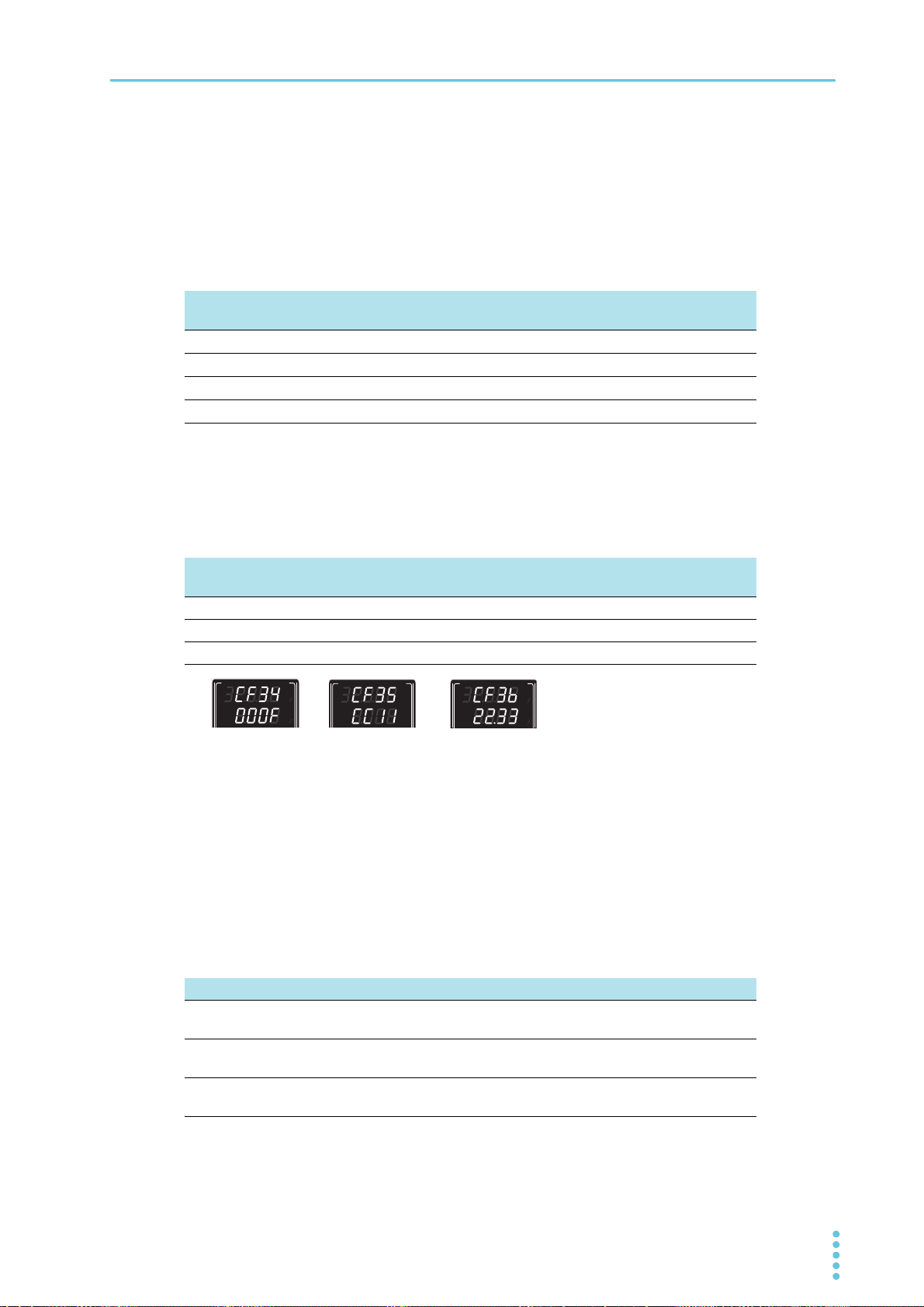
Basic Functions | CONFIG Settings
Display example of the MAC
address "00.0F.CE.11.22.33"
CF34: 00.0F
CF36: 22.33
CF35: CE.11
CV
V
s
CC
A
s
%
%
CV
V
s
CC
A
s
%
%
CV
V
s
CC
A
s
%
%
CF30 to CF33 (IP1 to IP4) IP address display
These parameters display the set IP addresses.
To set a fixed IP address, set it from the panel (CF42 to CF45) or from the Web browser interface. When
you access the PMX through a Web browser, do so under conditions in which a DHCP server or AUTO IP
can be used.
For details on the Web browser interface, see the Communication Interface Manual on the included CDROM.
Parameter
Display Description
number
CF30
CF31
CF32
CF33
0to255
0to255
0to255
0to255
0 to 255 First octet of the IP address
0 to 255 Second octet of the IP address
0 to 255 Third octet of the IP address
0 to 255 Fourth octet of the IP address
CF34 to CF36 (HA1 to HA3) MAC address display
These parameters display the set MAC addresses.
MAC addresses are set to 00.0F.CE.xx.xx.xx (where x is a hexadecimal number between 0 and F).
Parameter
number
CF34
CF35
CF36
Display Description
00.0F
CE.XX
XX.XX
00.0F First and second octets of the MAC address
CE.xx Third and fourth octets of the MAC address
xx.xx Fifth and sixth octets of the MAC address
CF40 (BOOT) LANsetting reset (LCI/ dEF) or apply (APPL)
Sets whether to reset or apply the LAN interface settings.
Then, press SET twice to execute the reset or application.
If you select to reset the LAN interface settings (LCI (LCI)/DEF (Default)), the security password will be
cleared, and the PMX will be in a security-disabled state.
If the LAN LED turns red (p.9), set the settings again.
For details on the LAN interface settings, see the “Communication Interface Manual” on the included CDROM.
Display Description
LCI LAN Configura-
tion Initialize
DEF Default Resets the LAN interface and host name settings (to their factory
APPL Apply The LAN interface is restarted, and the CONFIG settings are
Resets the LAN interface settings (to their factory default values)
default values)
applied.
PMX_MULTI User’s Manual 49
Page 50
Basic Functions | CONFIG Settings
CF41 (ADR) IP address assignment method
Sets the IP address assignment method.
Set whether to use (on: 1) or not use (off: 0) the following: DHCP server, AUTO IP function (automatic
assignment), and MANUAL IP function (manual assignment).
If DHCP and AUTO IP are both set to on and an IP address is not assigned through a DHCP server, AUTO
IP is used.
To use MANUAL IP, set DHCP and AUTO IP to off. The IP address that is assigned by the AUTO IP function is 169.254.x.x (where x is a number between 1 and 254).
To apply the setting, turn off the power and then turn it back on or execute “APPL (Apply)” using CF40.
Display Description
001 001 DHCP: off, AUTO IP: off, MANUAL IP: on
010 010 DHCP: off, AUTO IP: on, MANUAL IP: off
011 011 DHCP: off, AUTO IP: on, MANUAL IP: on
100 100 DHCP: on, AUTO IP: off, MANUAL IP: off
101 101 DHCP: on, AUTO IP: off, MANUAL IP: on
110 110 DHCP: on, AUTO IP: on, MANUAL IP: on (factory default setting)
111 111 DHCP: on, AUTO IP: on, MANUAL IP: on
CF42 to CF45 (S.IP1 to S.IP3) Manual IP address setting (MANUAL IP)
If you are not using the DHCP server or the AUTO IP function, set the IP address manually. To do so, use
CF41 to set MANUAL IP to on.
To apply the setting, turn off the power and then turn it back on or execute “APPL (Apply)” using CF40.
Parameter
number
CF42
CF43
CF44
CF45
Display Description
0.to255
0.to255
0.to255
0.to255
0 to 255 First octet of the IP address
0 to 255 Second octet of the IP address
0 to 255 Third octet of the IP address
0 to 255 Fourth octet of the IP address
CF46 (SUB) IP address subnet mask
If you want to set the IP address manually (MANUAL IP), set the subnet mask prefix. To do so, use CF41
to set MANUAL IP to on.
To apply the setting, turn off the power and then turn it back on or execute “APPL (Apply)” using CF40.
Display Description
16 to 31
16to31
Example: Display example when “16” is selected 255.255.0.0
Display example when “24” is selected 255.255.255.0
Display example when “31” is selected 255.255.255.254
Sets the subnet mask prefix (the factory default setting is 24)
50 User’s Manual PMX_MULTI
Page 51
Basic Functions | CONFIG Settings
CF50 (VID) Vendor ID (VID) and (PID) product ID (PID) display
Displays the USB vendor ID and product ID.
The vendor ID is shown in the CH1 display area and the product ID in the CH2 display area.
Display Vendor ID.
0B3E 0b3E 0x0B3E
Model Display Product ID:
PMX32-3DU 102A 102A 0x102A
PMX32-3TR 102B 102B 0x102B
PMX32-2QU 102C 102C 0x102C
CF51 (BAUD) RS232C baud rate
Sets the baud rate of the RS232C interface.
This parameter is applied when you turn the POWER switch off and on.
Display Baud rate
1.2 1.2 1200 bps
2.4 2.4 2400 bps
4.8 4.8 4800 bps
9.6 9.6 9600 bps
19.2 19.2 19 200 bps (factory default setting)
38.4 38.4 38 400 bps
57.6 57.6 57 600 bps
115.2 115.2 115200 bps
CF60 (VER) Firmware version and (BLD) build number display
Displays the firmware version and build number.
The firmware version is shown in the CH1 display area and the build number in the CH2 display area.
Display The firmware version
VX.XX Vx.xx
Display Build number
XXXX xxxx
Ver. x.xx
BLDxxxx
(where x is between 0 and 9)
(where x is between 0 and 9)
PMX_MULTI User’s Manual 51
Page 52
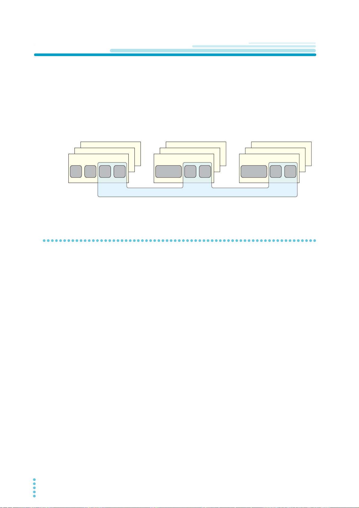
Basic Functions
Memory C
Memory B
Memory A
Normal operation [save/recall]
CH1 CH2 CH3 CH4
Memory C
Memory B
Memory A
CH2
(master)
CH2
(master)
CH3 CH4
Memory C
Memory B
Memory A
CH3 CH4
Series operation [save/recall]
Same settings
Parallel operation [save/recall]
Example of PMX32-2QU
Memory Function
There are memory areas for saving combinations of voltage, current, OVP, OCP, and output-on delay/ off
delay settings. Saved settings can be recalled from the memory when needed.
There are three memory areas (A,B, and C) for normal operation, parallel operation, and series operation.
For normal operation, the settings of all channels can be stored and recalled.
For parallel operation and series operation, the master (CH2) settings can be stored and recalled.
For the other channels of PMX32-3TR/ PMX32-2QU, the applied settings can be stored and recalled,
which are shared between normal operation, parallel operation, and series operation.
Saving settings
Press SELECT to select the channel you want to configure.
1
The selected channel is indicated with brackets.
Press SET.
2
“SET” appears, and the present voltage and current are displayed on the panel.
While viewing the panel display, turn the VOLTAGE and CURRENT knobs to set the
3
voltage, current, OVP, OCP, and output-on delay/ off delay.
To set other channels, repeat step 1 and step 3.
4
Hold down memory key A (SHIFT+OVP•OCP), B (SHIFT+CONFIG), or C
5
(SHIFT+LOCK) until the destination where the settings will be saved to (PRESET A,
B, or C) appears.
The status display area shows the selected memory area (A, B, or C), and the settings are saved.
When you press SET, the “SET” indicator appears in the display area, and the saved settings are
displayed.
This completes the setting.
By following step 5, you can save to the memory when the output is on and the measurement display is
shown (“SET” not shown). After saving to memory, press SET to check the memory settings.
If settings are recalled from the memory during normal operation, the settings saved to all channels will be
recalled.
52 User’s Manual PMX_MULTI
Page 53

Basic Functions | Memory Function
Recalling settings
You can recall settings from the memory on the measurement display (“SET” not shown) or the setting display (“SET” shown).
The contents in the memory are recalled to all channels.
If the output is on, the settings are applied to the output the moment they are recalled.
There are two ways to recall settings from memory. One way is to display the saved contents and recall
them after confirming them (CF02: ON), and the other is to recall them immediately (CF02: OFF).
If you hold down memory key A (SHIFT+OVP•OCP), B (SHIFT+CONFIG), or C
(SHIFT+LOCK), the present settings will be saved to the memory.
Displaying the saved contents and recalling them after confirmation
Use the CONFIG settings to set the PMX to display the saved contents of the mem-
1
ory (CF02: ON).
Press the key of the memory you want to recall from: A (SHIFT+OVP•OCP), B
2
(SHIFT+CONFIG), or C (SHIFT+LOCK).
The selected memory area (A, B, or C) blinks.
Check the displayed settings, and then press SET.
3
The selected memory area (A, B, or C) changes from blinking to solid. The recalled memory contents (voltage and current) are displayed and applied to the output.
Press LOCAL to cancel recalling.
Recalling the saved contents without displaying them
Use the CONFIG settings to set the PMX to hide the saved contents of the memory
1
(CF02: OFF).
Press the key of the memory you want to recall from: A (SHIFT+OVP•OCP), B
2
(SHIFT+CONFIG), or C (SHIFT+LOCK).
The display area shows the selected memory area (A, B, or C), and the settings are recalled.
PMX_MULTI User’s Manual 53
Page 54
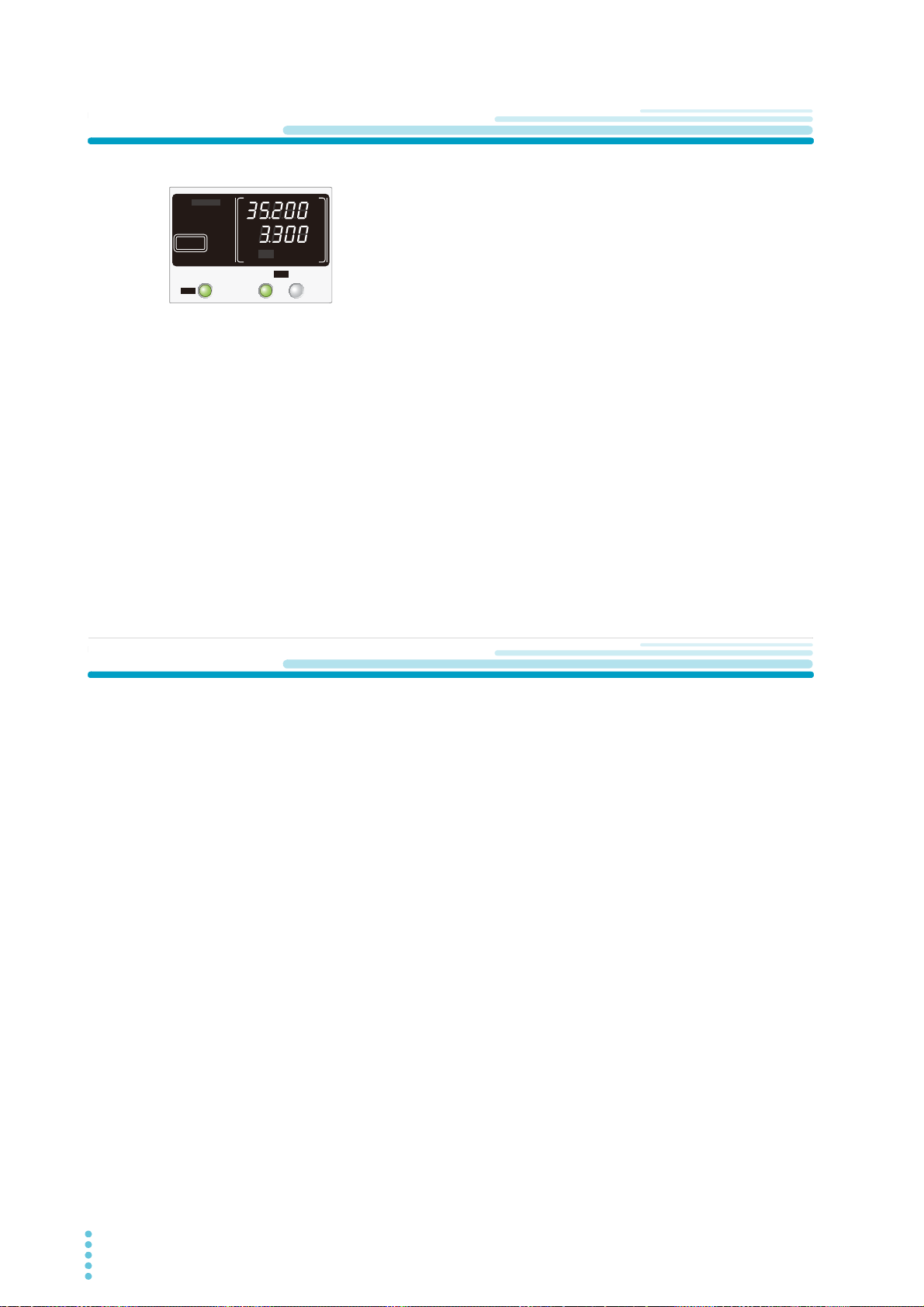
Basic Functions
SELECTOUTPUT
CH1
OUTPUT
ALL
CV
V
s
OFF
CC
A
s
ON
PRLSER
TRACKING 12
LOCK
REMOTE
LAN LAN
DEL AY
DEL AY SET
SET OVP࣭OCP
PRESET A BC
ALARM
%
%
Locking the Panel Controls (Key Lock)
The key lock function can be used to prevent the settings from being
changed by mistake.
When the keys are locked, “LOCK” is shown in the display area.
There are three key lock types. Use CONFIG parameter CF03 to set the type.
• Key lock 1 (Loc1): Lock all keys except the OUTPUT and memory A, B, and C keys.
• Key lock 2 (Loc2): Locks all keys except the OUTPUT key.
• Key lock 3 (Loc3): Lock all keys and the rotary knob.
Configure all the parameters, such as the output voltage and output current, as
1
necessary.
Hold down LOCK until “LOCK” appears in the display area.
2
Key lock is enabled.
To release the key lock, hold down LOCK until “LOCK” disappears.
Tracking Function
The tracking function varies the outputs simultaneously.
The outputs of other channels change simultaneously along with the reference channel.
The outputs can be varied according to the amount of change (TRACKING 1: absolute value change) or
varied at the same percentage (TRACKING 2: percentage change).
If within the operating area, the outputs can change from 0 V (or 0 A) to the rated output voltage (or rated
output current).
You can specify the channels that will operate in tracking mode with CONFIG parameter CF09.
When set to tracking mode, parallel operation nor series operation can be used.
54 User’s Manual PMX_MULTI
Page 55

Basic Functions | Tracking Function
TRACKING 1 (absolute value change)
The outputs of target channels change to the same values (absolute values) along with the changes in the
reference channel. When TRACKING 1 is enabled, the voltage and current set at that moment become
the reference values, and changes are made from there.
If the output of a target channel reaches its maximum output setting or 0 V (or 0 A) when the voltage or
current of the reference channel is changed, the display no longer changes but the amount of change in
the target channel is recorded. When the output of the reference channel is returned to its original output
value, the outputs of channels operating in tracking mode will also return to their original values. (See
example 1.)
It is possible to change the reference channel during tracking operation. The state when the change is
made becomes the reference, and the outputs change accordingly. (See example 2.)
It is possible to change the reference value of the reference channel during tracking operation. You can do
this by selecting the reference channel with the SELECT key and changing the value.
Here we will use TRACKING 1 on CH1 and CH2 of a PMX32-2QU.
Example 1: Settings: CH1 = 25.00 V, CH2 = 30.00 V. The reference channel is set to CH1.
[CH1] [CH2]
25.00 V 30.00 V
▼ ► Increase CH1 by 4 V.
29.00 V 32.00 V
▼ ► Decrease CH1 by 1 V.
28.00 V 32.00 V CH2 stays at 32 V because 34 V - 1 V = 33 V.
▼ ► Decrease CH1 by 2 V.
26.00 V 31.00 V CH2 becomes 33 V - 2 V = 31 V.
▼ ► Decrease CH1 by 1 V.
25.00 V 30.00 V The output returns to its original reference voltage.
Reference voltage
Set TRACKING1.
CH2 stops at its maximum output, but the amount of change
(30 V + 4 V = 34 V) is recorded.
Example 2: Settings: CH1 = 25.00 V, CH2 = 30.00 V. The reference channel is set to CH1 and changed to
CH2 in the middle.
[CH1] [CH2]
25.00 V 30.00 V
▼ ► Increase CH1 by 4 V.
29.00 V 32.00 V
▼
29.00 V 32.00 V
▼ ► Decrease CH2 by 1 V.
28.00 V 31.00 V CH2 becomes 32.00 V - 1 V = 31.00 V.
▼ ► Decrease CH2 by 1 V.
27.00 V 30.00 V
Reference voltage
Set TRACKING1.
CH2 stops at its maximum output, but the amount of change
(30 V + 4 V = 34 V) is recorded.
► Press SELECT to select CH2 to change the reference chan-
nel to CH2.
The reference voltage changes to 32.00 V, and the amount of
change is cleared.
CH2 returns to its original reference voltage, but CH1 becomes
27.00 V and does not return to the original reference value.
PMX_MULTI User’s Manual 55
Page 56
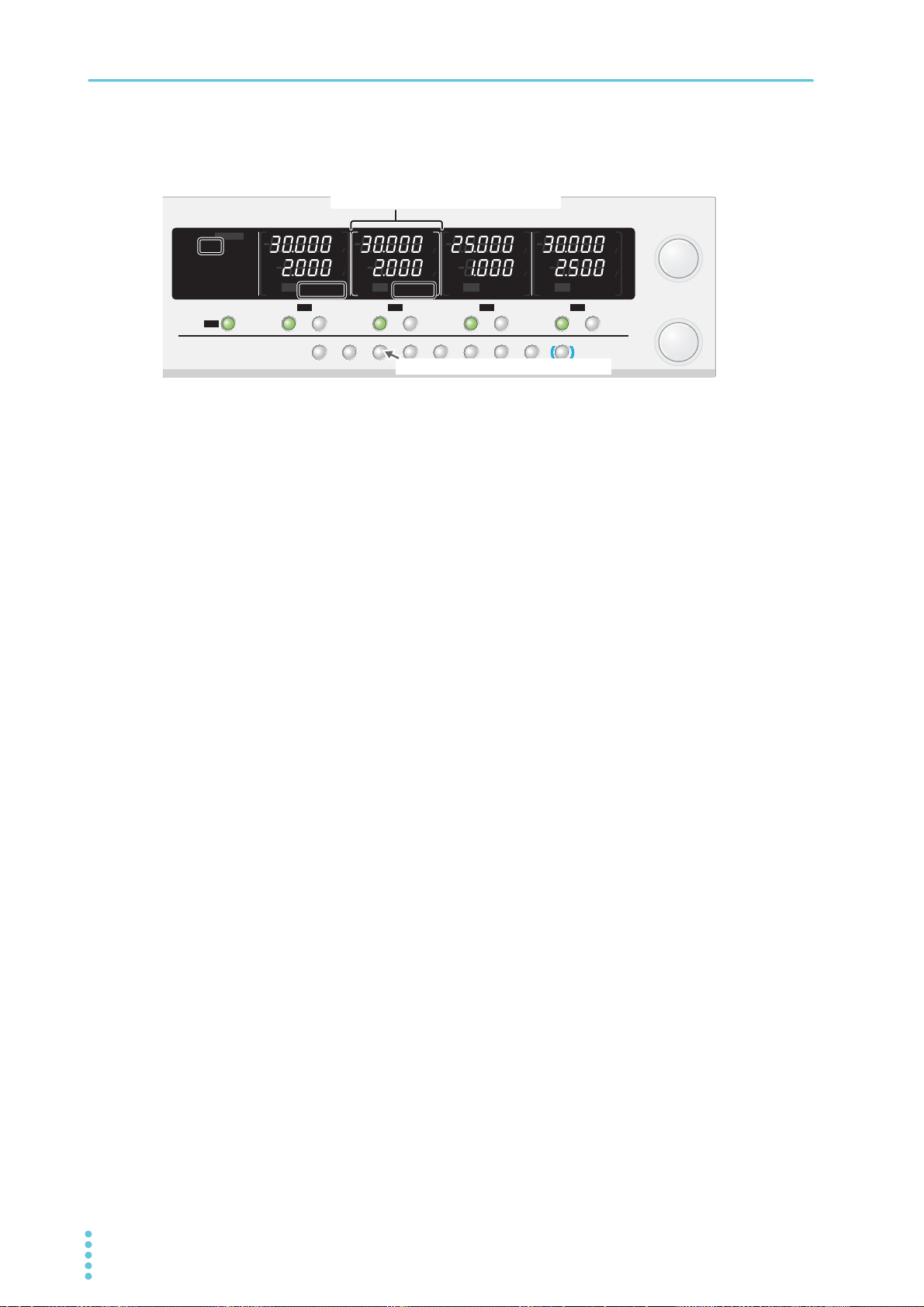
Basic Functions | Tracking Function
TRACK DELAY
CBA
ALM CLR
DELAY SETTRACK SET
PRLSER
OVP࣭OCP
SET LOCKCONFIG
SELECTOUTPUT
CH1
SELECTOUTPUT
CH2
SELECTOUTPUT
CH3
SELECTOUTPUT
CH4
OUTPUT
ALL
FINE
CURRENT
FINE
VOLTAGE
LOCAL
SHIFT
CV
V
s
OFF
CC
A
s
ON
PRLSER
TRACKING 12
LOCK
REMOTE
LAN LAN
DEL AY
DEL AY SET
SET OVP࣭OCP
PRESET A BC
ALARM
CV
V
s
OFF
CC
A
s
ON
PRLSER
TRACKING 12
CV
V
s
OFF
CC
A
s
ON
PRLSER
TRACKING 12
CV
V
s
OFF
CC
A
s
ON
PRLSER
TRACKING 12
%%%%
%%%%
TRACK/TRACK SET(SHFT+TRACK) key
Reference channel (indicated with brackets)
Reference voltage and reference current
Example of PMX32-2QU (reference channel: CH2, TRACING 1 operation: CH1 and CH2)
Procedure for TRACKING 1 (absolute value change)
Press OUTPUT ALL to turn off the output.
1
Using CONFIG settings, select the channels that will operate in tracking mode
2
(CF09: OFF/ ON) (p.47).
Set the output values of the channels that will operate in tracking mode.
3
Press TRACK to enter TRACKING 1 mode. If TRACKING 2 is displayed, press
4
TRACK SET (SHIFT+TRACK) to change.
TRACKING 1 is shown in the display areas of the channels that will operate in tracking mode.
Press TRACKING SET (SHIFT+TRACK) to switch between TRACKING 1 and TRACKING 2.
Press SELECT to select the reference channel for TRACKING 1.
5
The selected channel is indicated with brackets.
Press the OUTPUT key of the channel that will operate in tracking mode to turn the
6
output on.
Based on the output of the reference channel, turn the rotary knob to set the
7
desired output.
To clear the TRACKING 1 operation, press TRACK.
56 User’s Manual PMX_MULTI
Page 57
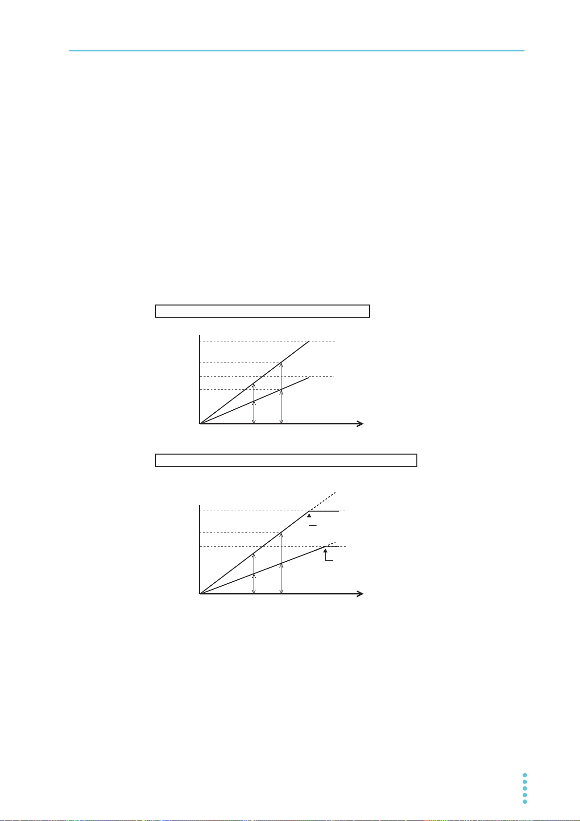
Basic Functions | Tracking Function
0
Example when the voltage is changed within the rated output
Example when the voltage is changed above the maximum settable output
Maximum voltage
Maximum voltage
0
When the maximum voltage is
reached, the display stops changing.
But, the amount of change is
recorded.
a
b
c
d
100 % 200 %
CH1
CH3
Voltage setting
Voltage setting
Maximum
settable voltage
Maximum
settable voltage
Voltage setting
Voltage setting
Maximum
settable voltage
Maximum
settable voltage
Output
a
b
c
d
100 % 200 %
CH1
CH3
Output
TRACKING 2 (percentage change)
The outputs of target channels change at the same percentage along with the changes in the reference
channel. When TRACKING 2 is enabled, the voltage and current set on each channel at that moment
become the reference values (100 %), and changes are made from there.
If the output of a target channel reaches its maximum output setting or 0 V (or 0 A) when the reference
channel percentage is changed, the display no longer changes but the amount of change in the target
channel is recorded. When the output is returned to its original value (100 %), the outputs of the target
channels also return to their original values.
Example: Here we will use TRACKING 2 on CH1 and CH2 of a PMX32-2QU.
When you turn the rotary knob during tracking operation, the outputs change at the same percentage
as the preset output percentage (b/a).
b/a = d/c
This proportional expression is satisfied.
PMX_MULTI User’s Manual 57
Page 58
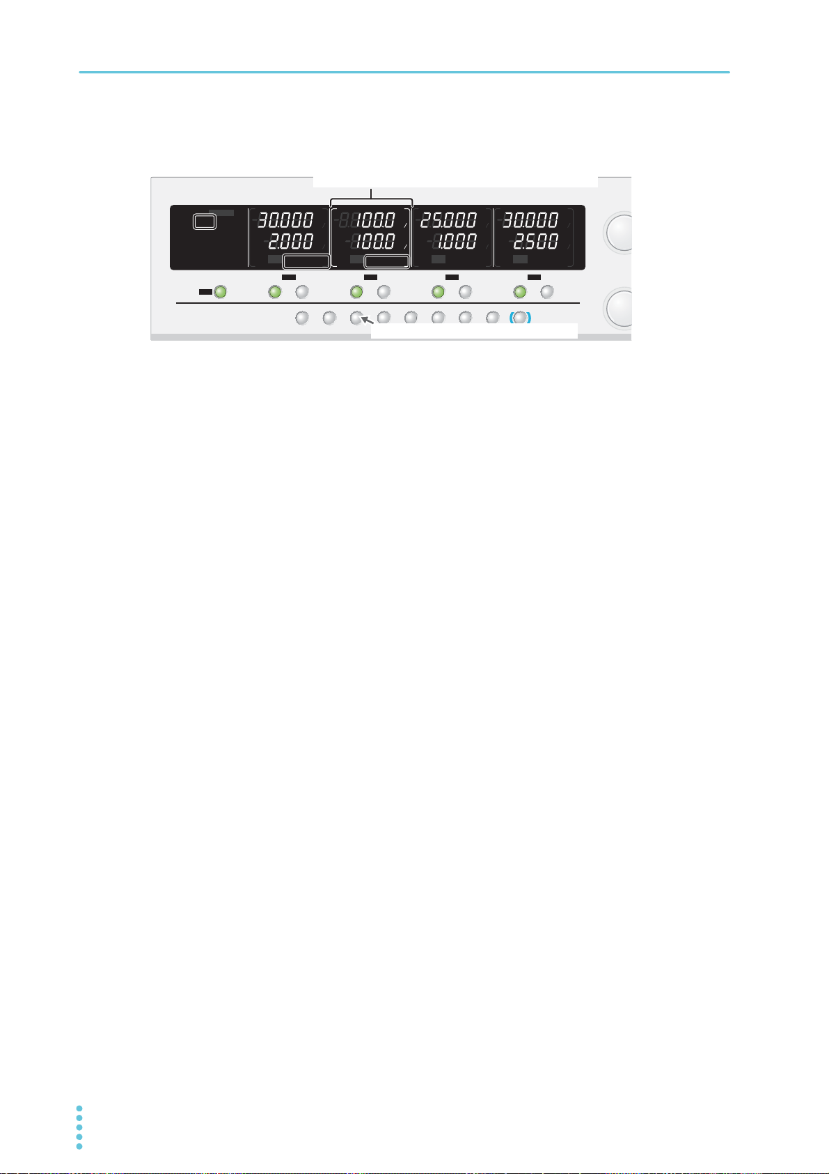
Basic Functions | Tracking Function
TRACK DELAY
CBA
ALM CLR
DELAY SETTRACK SET
PRLSER
OVP࣭OCP
SET LOCKCONFIG
SELECTOUTPUT
CH1
SELECTOUTPUT
CH2
SELECTOUTPUT
CH3
SELECTOUTPUT
CH4
OUTPUT
ALL
FINE
CURRE
FINE
VOLTA
LOCAL
SHIFT
CV
V
s
OFF
CC
A
s
ON
PRLSER
TRACKING 12
LOCK
REMOTE
LAN LAN
DEL AY
DEL AY SET
SET OVP࣭OCP
PRESET A BC
ALARM
CV
V
s
OFF
CC
A
s
ON
PRLSER
TRACKING 12
CV
V
s
OFF
CC
A
s
ON
PRLSER
TRACKING 12
CV
V
s
OFF
CC
A
s
ON
PRLSER
TRACKING 12
%%%%
%%%%
TRACK/TRACK SET(SHFT+TRACK) key
Reference channel (indicated with brackets)
Reference voltage and reference current displayed as 100 %
Example of PMX32-2QU (reference channel: CH2, TRACING 1 operation: CH1 and CH2)
Procedure for TRACKING 2 (percentage change)
Press OUTPUT ALL to turn off the output.
1
Using CONFIG settings, select the channels that will operate in tracking mode
2
(CF09: OFF/ ON) (p.47).
Set the output values of the channels that will operate in tracking mode.
3
Press TRACK to enter TRACKING 2 mode. If TRACKING 1 is displayed, press
4
TRACK SET (SHIFT+TRACK) to change.
TRACKING 2 is shown in the display areas of the channels that will operate in tracking mode.
Press TRACKING SET (SHIFT+TRACK) to switch between TRACKING 1 and TRACKING 2.
Press SELECT to select the reference channel for TRACKING 2.
5
The selected channel is indicated with brackets.
In the setting display, the voltmeter and ammeter show “100.0 %”.
Press the OUTPUT key of the channel that will operate in tracking mode to turn the
6
output on.
Based on the percentage of the reference channel, turn the rotary knob to set the
7
desired output.
Press SET to switch between voltage/current display and percentage display.
To clear the TRACKING 2 operation, press TRACK.
58 User’s Manual PMX_MULTI
Page 59
Remote Control
SELECTOUTPUT
CH1
OUTPUT
ALL
CV
V
s
OFF
CC
A
s
ON
PRLSER
TRACKING 12
LOCK
REMOTE
LAN LAN
DEL AY
DEL AY SET
SET OVP࣭OCP
PRESET A BC
ALARM
%
%
You can remotely control the product from a PC using SCPI commands through the LAN, USB, or GPIB
interface. Moreover, with the LAN interface, you can use the Web browser interface to remotely control the
product from a virtual front panel. For details on remote control, see the Communication Interface Manual.
Switching from Remote Mode to Local Mode
When the product is being controlled remotely, “REMOTE” is shown in the
display area.
To switch the product back to local mode from the front panel, press
LOCAL.
Basic Functions
PMX_MULTI User’s Manual 59
Page 60

External Control
The CONTROL TERMINAL on the rear panel can be used to perform the following external controls.
• Turning output on and off using an external contact
• Alarm input using an external contact
• External monitoring of the operating status
60 User’s Manual PMX_MULTI
Page 61
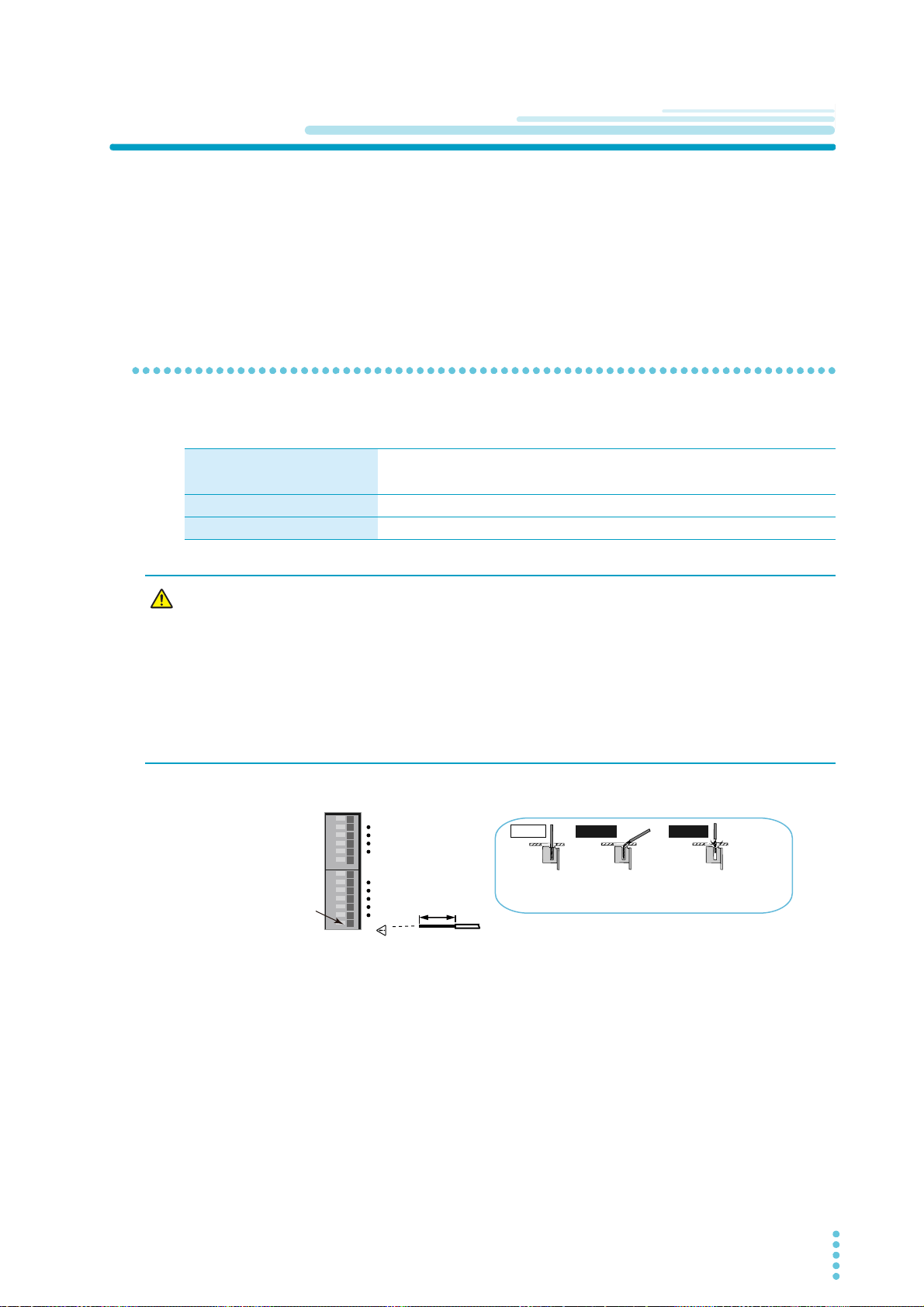
CONTROL TERMINAL
AWG20-28
STRIP
-
GAUGE
8mm
17813
CONTROL TERMINAL
Incorrect
Incorrect
Correct
The wire itself is
in contact with the
chassis.
Wire scraps are
in contact with the
chassis.
While pressing
here with a
screwdriver, insert
the wire.
The CONTROL TERMINAL is a screw-less terminal.
The parts necessary to connect to the CONTROL TERMINAL are not included. Use parts that match the
connector to make the connections.
For information about how to obtain these tools or replacement parts, contact your Kikusui agent or distributor.
Connecting the CONTROL TERMINAL
Cables and tools that are necessary to make the connection
Wire Single wire: Ø0.32 (AWG28) to Ø0.81 (AWG20)
2
Stranded wire: 0.08 mm
Flat-blade screwdriver Tip thickness: 0.5 mm
Wire stripper A wire stripper that matches the wires listed above
(AWG28) to 0.52 mm2 (AWG20)
External Control
WARNING
Turn the POWER switch off.
1
Remove 8 mm of the wire covering, and connect the wire to the CONTROL TERMI-
2
NAL.
Risk of electric shock and damage to internal circuits.
• Never connect to the CONTROL TERMINAL while the POWER switch is turned on.
• Insert the cables so that the wire strands do not touch the chassis when they stick
out of the CONTROL TERMINAL. Also, insert the cables so that the stripped wires
do not stick out of the terminal block.
• For connecting to the CONTROL TERMINAL, use cables with a voltage rating that is
higher than the product’s isolation voltage. For details on the isolation voltage of
each model, see “Specifications” (p.85).
Remove the screwdriver, and check that the wire does not come loose.
3
This completes the connections.
PMX_MULTI User’s Manual 61
Page 62
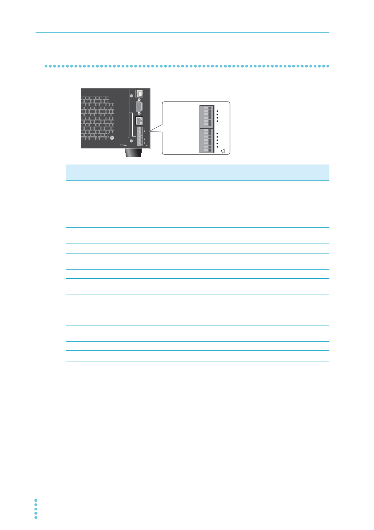
External Control | CONTROL TERMINAL
Pin numbers of
the CONTROL
TERMINAL
RS232C USBLAN
17813
CONTROL TERMINAL
17813
CONTROL TERMINAL
1. CH1 OUT ON STATUS
2. CH2 OUT ON STATUS
3. CH3 OUT ON STATUS
(
TR QU
)
4. CH4 OUT ON STATUS
(
QU
)
5. POWER ON STATUS
6. ALARM STATUS
7. STATUS COM
8. CH1 OUT ON
/
OFF CONTROL
9. CH2 OUT ON
/
OFF CONTROL
10. CH3 OUT ON
/
OFF CONTROL
(
TR QU
)
11. CH4 OUT ON
/
OFF CONTROL
(
QU
)
12. ALARM IN
13. FRAME GND
AWG 20-28
STRIP GAUGE
8mm
Pin arrangement of the CONTROL TERMINAL
Pin
Signal name Description
no.
1OUTPUT ON STATUS
(CH1)
2OUTPUT ON STATUS
(CH2)
3OUTPUT ON STATUS
(CH3)
4OUTPUT ON STATUS
(CH4)
5 POWER ON STATUS
6 ALARM STATUS On when a protection function (OVP, OCP, OHP, WATCHDOG) is activated
7 STATUS COM Status signal common for pins 1 to 6.
8 OUTPUT ON/ OFF
CONTROL (CH1)
9 OUTPUT ON/ OFF
CONTROL (CH2)
10 OUTPUT ON/ OFF
CONTROL (CH3)
11 OUTPUT ON/ OFF
CONTROL (CH4)
12 ALARM IN All channel outputs are turned off when an alarm signal is received.
13 FRAME GND
*1. Open collector output: Maximum voltage of 30 V and maximum current of 8 mA.
The status common is floating (isolation voltage or less). It is isolated from the control circuit.
*2. FRAME GND is connected to the chassis.
On when output is on (output through an open-collector photocoupler).
On when output is on (output through an open-collector photocoupler).
On when output is on (output through an open-collector photocoupler).
On when output is on (output through an open-collector photocoupler).
On when the power is on (output through an open-collector photocoupler).
or when an alarm signal (ALARM IN) is received.
Output on/off control using external contact input
Output on/off control using external contact input
Output on/off control using external contact input
Output on/off control using external contact input
External signal common for pins 8 to 12.
*1
*1
*1
*1
*1
*2
62 User’s Manual PMX_MULTI
Page 63

Output On/Off Control
This section explains how to use an external contact to control the output on and off states.
External Control
WARNING
To reduce the influence of noise on the output, connect a 2-core shielded wire or a twisted-pair wire across
the external contact, and keep the wire as short as possible. If the wiring is long, it becomes easy for noise
to influence the operation of the PMX. Even if you use cables that are designed to suppress noise, the
PMX may not operate properly.
If you use a shielded cable, connect the shield to the chassis or ground.
To use an external contact to control the output on and off states, set the appropriate CONFIG parameter
(CF04: ON). Then, select the logic setting from the following two options.
• Turn the output on with a LOW level signal (CF05: LO)
When pin 8 (CH1), pin 9 (CH2), pin 10 (CH3), or pin 11 (CH4) of the CONTROL TERMINAL is set to
LOW level (0 V to 0.5 V) or is shorted, the output is turned on.
• Turn the output on with a HIGH level signal (CF05: HI)
When pin 8 (CH1), pin 9 (CH2), pin 10 (CH3), or pin 11 (CH4) of the CONTROL TERMINAL is set to
HIGH level (4.5 V to 5 V) or is opened, the output is turned on.
Risk of electric shock.
• Ensure that the insulation of external contact (S) and the connected cable is greater
than or equal to the isolation voltage of the product. For details on the isolation
voltage of each model, see “Specifications” (p.85).
• When using shielded cables for the connection, protect the uncovered sections of
the shielded cable by using insulation tubes whose withstand voltage is greater
than the PMX’s isolation voltage.
When you are using an external contact to control the output on and off states, the OUTPUT and OUTPUT
ALL keys on the front panel are disabled.
If the delay function is enabled (“DELAY” is shown), you cannot use an external contact to control the output on and off states (CF04). Disable the delay function.
PMX_MULTI User’s Manual 63
Page 64
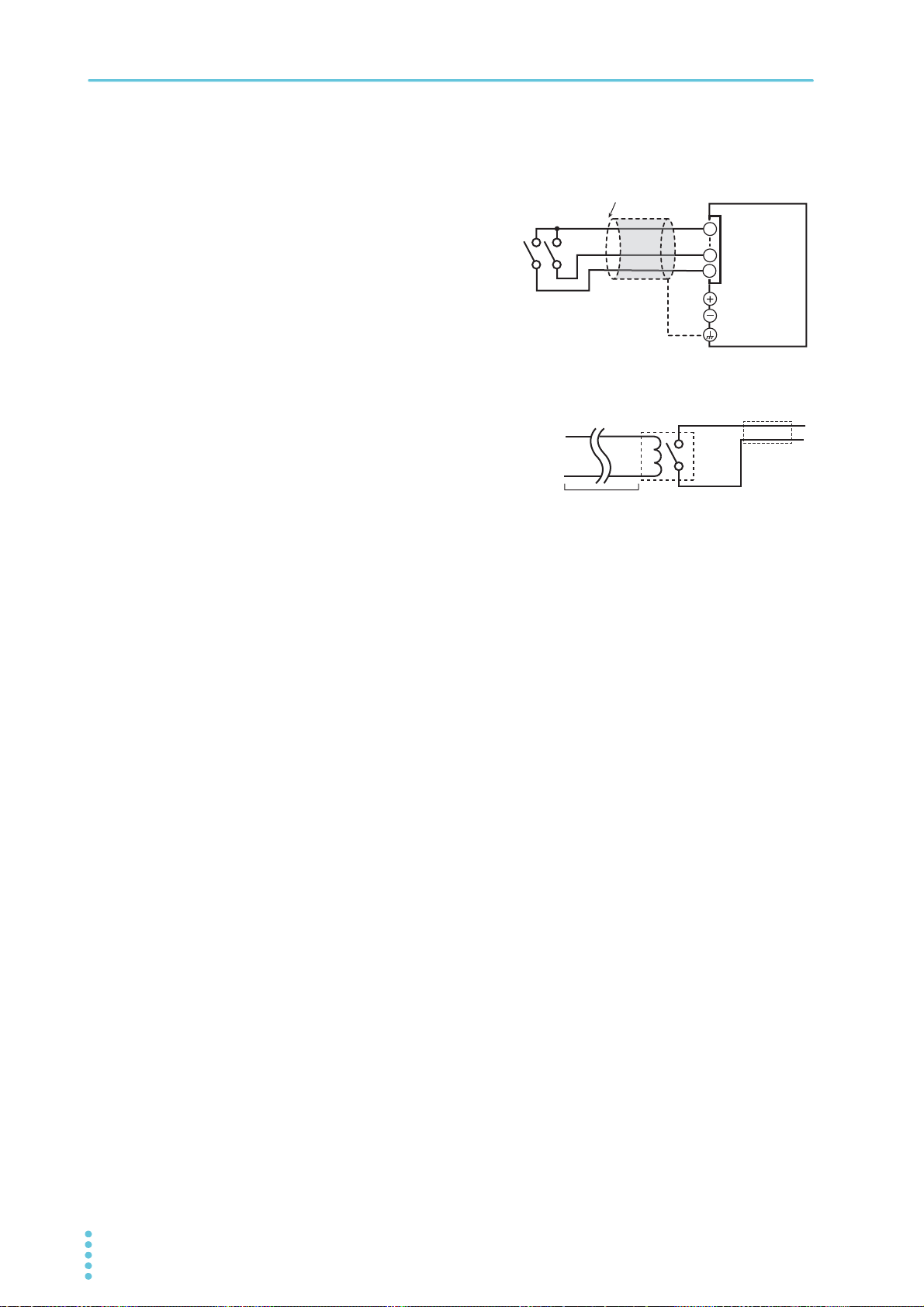
External Control | Output On/Off Control
2-core shielded wire or
Twisted pair wires
Output terminal
Chassis terminal
J1
13
PMX
Switch
9
8
Example in which pin 8 (CH1) and pin 9 (CH2)
are connected
Relay
External contact connection
Pin 8 (CH1), pin 9 (CH2), pin 10 (CH3), or pin 11 (CH4)
and pin 13 of the CONTROL TERMINAL are used.
The open-circuit voltage across pin 8 (CH1), pin 9
(CH2), pin 10 (CH3), or pin 11 (CH4) and 13 is approximately 3.5 V, and the short-circuit current is approximately 0.75 mA.
Use external contacts that have a contact rating greater
than or equal to 1 mA at 5 Vdc.
For long-distance wiring
When you are wiring over a great distance, use a small relay
and extend the coil side of the relay.
Switch
Extend this line.
64 User’s Manual PMX_MULTI
Page 65
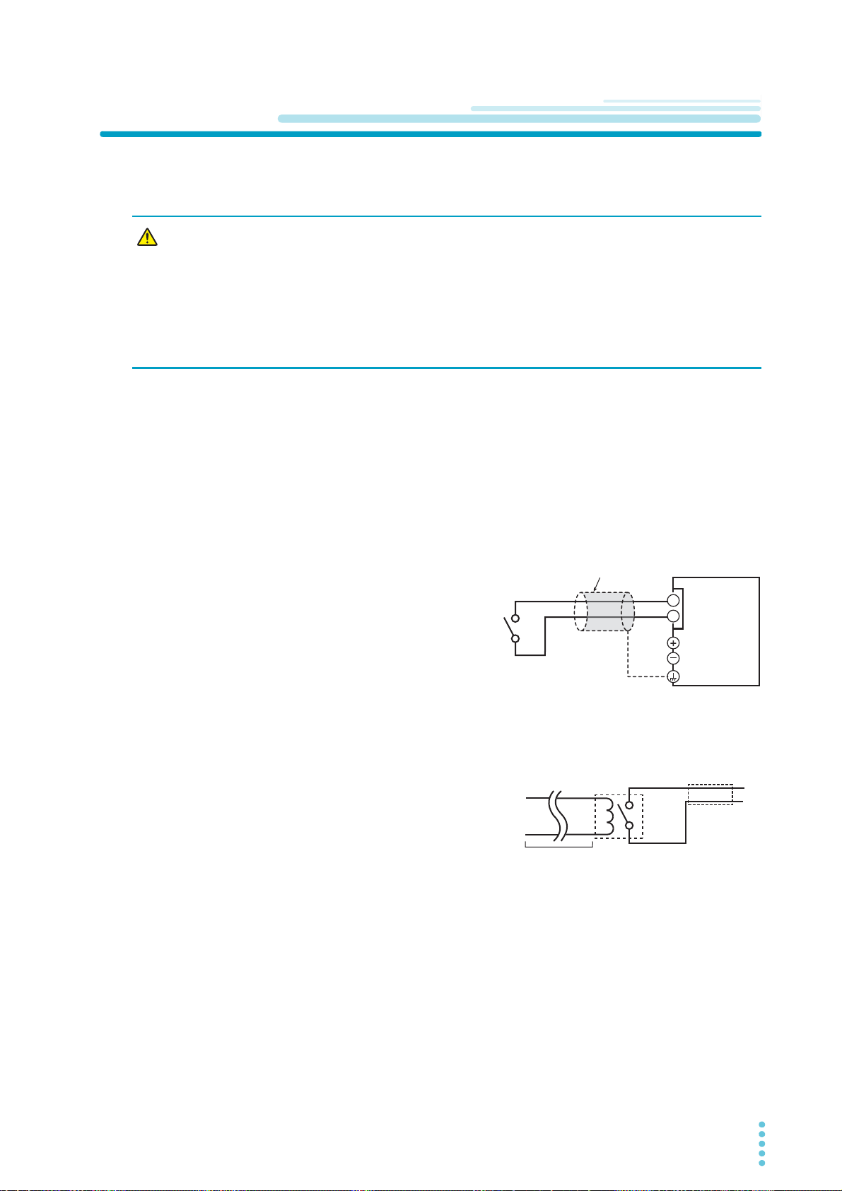
Alarm Input
2-core shielded wire or
Twisted pair wires
Output terminal
Chassis terminal
J1
13
12
PMX
Switch
Switch
Extend this line.
Relay
This section explains how to use an alarm signal input through an external contact to turn the output off.
To apply an alarm signal, short the contact switch for at least 0.5 s.
External Control
WARNING
To reduce the influence of noise on the output, connect a 2-core shielded wire or a twisted-pair wire across
the external contact, and keep the wire as short as possible. If the wiring is long, it becomes easy for noise
to influence the operation of the PMX. Even if you use cables that are designed to suppress noise, the
PMX may not operate properly.
If you use a shielded cable, connect the shield to the chassis.
Risk of electric shock.
• Ensure that the insulation of external contact (S) and the connected cable is greater
than or equal to the isolation voltage of the product. For details on the isolation
voltage, see “Specifications” (p.85).
• When using shielded cables for the connection, protect the uncovered sections of
the shielded cable by using insulation tubes whose withstand voltage is greater
than the PMX’s isolation voltage.
Alarm input connection
Pins 12 and 13 of the CONTROL TERMINAL are used.
The open-circuit voltage across pins 12 and 13 is
approximately 3.5 V, and the short-circuit current is
approximately 0.75 mA.
Use external contacts that have a contact rating
greater than or equal to 1 mA at 5 Vdc.
If two or more channels are floating, and you are using
a single external contact to apply the alarm signal, use
a relay or similar device for the external contact signal
to isolate the signal transmitted to each channel.
For long-distance wiring
When you are wiring over a great distance, use a small
relay and extend the coil side of the relay.
PMX_MULTI User’s Manual 65
Page 66
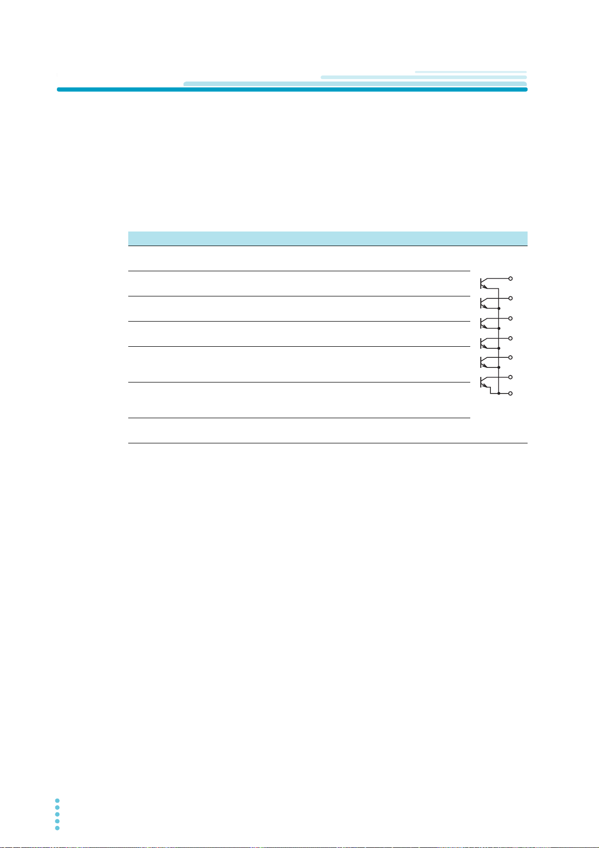
External Control
1
5
4
3
2
7
6
External monitoring of the operating status
The J1 connector has status outputs that can be used to externally monitor the operation status of the
product. The following six items make up the status outputs.
The outputs are open collector outputs of photocouplers; they are isolated from the internal circuits of the
product.
The status common is floating (that is, it has an isolation voltage of less than or equal to 70 V).
The maximum ratings of the signal terminals are as follows:
Maximum voltage: 30 V. Maximum current (sink): 8 mA.
Pin no. Signal name Description Circuit
1OUTPUT ON
STATUS (CH1)
2OUTPUT ON
STATUS (CH2)
3OUTPUT ON
STATUS (CH3)
4OUTPUT ON
STATUS (CH4)
5POWER ON
STATUS
6 ALARM STATUS This is set to LOW level when a protection function (OVP,
7 STATUS COM Status signal common for pins 1 to 6.
This is set to LOW level when the CH1 output is turned on.
Photocoupler open collector output.
This is set to LOW level when the CH2 output is turned on.
Photocoupler open collector output.
This is set to LOW level when the CH3 output is turned on.
Photocoupler open collector output.
This is set to LOW level when the CH4 output is turned on.
Photocoupler open collector output.
This is set to LOW level when the POWER switch is turned
on (POWER ON STATUS).
Photocoupler open collector output.
OCP, OHP, WATCHDOG) is activated or when an alarm
signal (ALARM IN) is received.
Photocoupler emitter output.
66 User’s Manual PMX_MULTI
Page 67
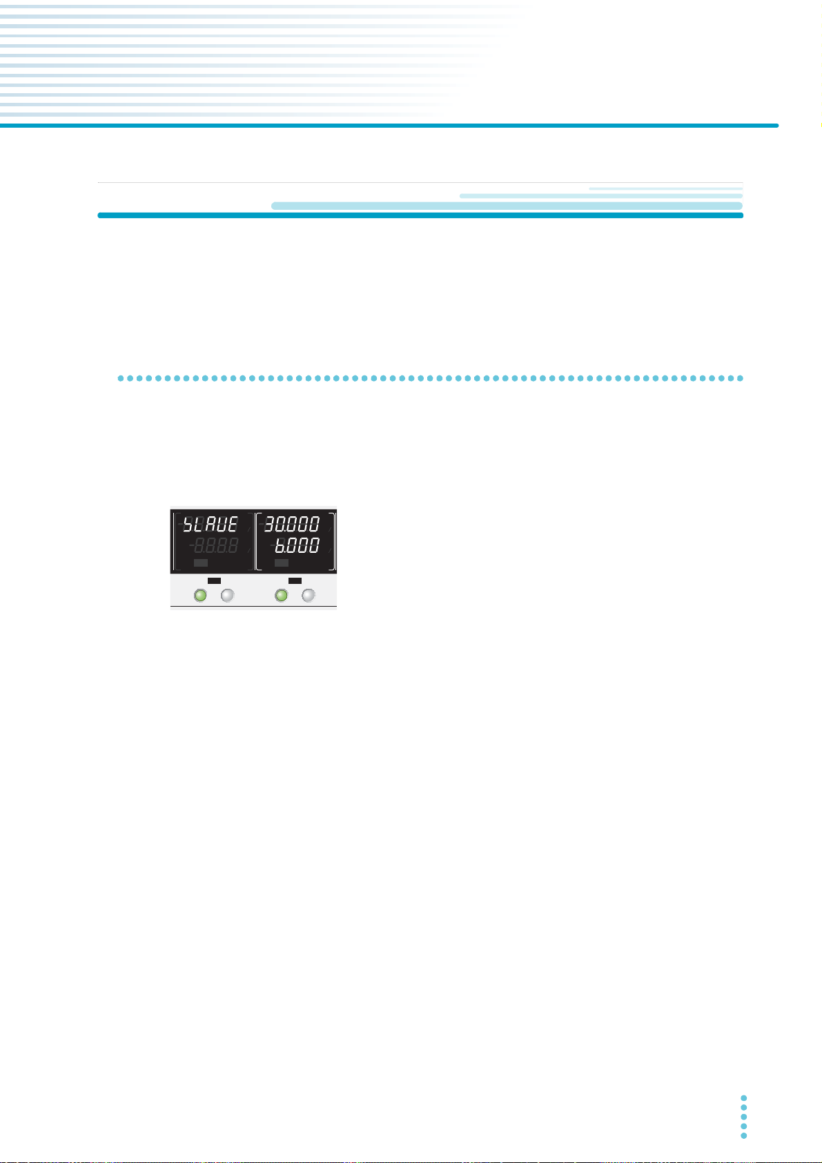
Parallel Operation and Series Operation
Panel display during parallel operation
Example when the output voltage is set to 30 V and the output current to 6 A
(CH1: 3 A+CH2: 3 A)
SELECTOUTPUT
CH1
SELECTOUTPUT
CH2
CV
V
s
OFF
CC
A
s
ON
PRLSER
TRACKING 12
CV
V
s
OFF
CC
A
s
ON
PRLSER
TRACKING 12
%%
%%
Overview of Parallel Operation
CH1 and CH2 can be connected in parallel inside the product to double the current output range. CH2
operates as the master channel and CH1 as the slave channel.
In parallel operation, the output current is the total of the CH1 and CH2 outputs.
Parallel operation functions
Voltage display and current display
The voltage or current is displayed on CH2 (master). The total current of CH1 and CH2 is displayed.
The CH1 voltmeter shows “SLAVE.”
Remote sensing
This is available (p.23).
The sensing terminal of CH2 (master) can be used.
Memory
This is available (p.52).
The values set on CH2 (master) during parallel operation can be saved and recalled.
For the other channels of PMX32-3TR/PMX32-2QU, the values are shared between normal operation,
parallel operation, and series operation.
External control
This is available (p.60).
To perform output on/off control, use pin 9 (CH2) and pin 13. Open pin 8 (CH1).
PMX_MULTI User’s Manual 67
Page 68

Parallel Operation and Series Operation | Overview of Parallel Operation
Alarms
Alarms that are detected on a channel are also detected during parallel operation (p.37).
Clearing alarms
Press ALM CLR (SHIFT+SET), or turn the POWER switch off and then on. If you do not resolve the cause
of the alarm, an alarm will occur again.
If an alarm still occurs even after you have resolved all the causes of alarms, the product may be malfunc-
tioning. Stop using it immediately, and contact your Kikusui agent or distributor.
68 User’s Manual PMX_MULTI
Page 69
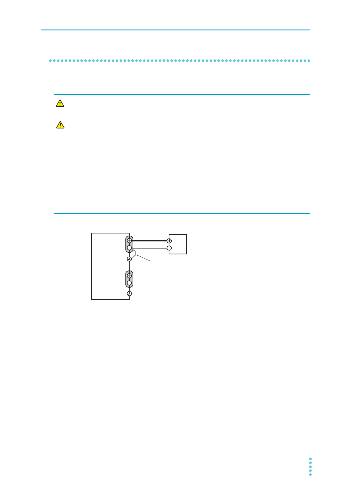
Parallel Operation and Series Operation | Overview of Parallel Operation
CAUTION
Load or
relay terminal block
PMX
Output terminal
CH2
Chassis terminal
Output terminal
CH1
Chassis terminal
Connect the output terminal of
one of the channels to the
chassis terminal.
Load connection for parallel operation (CH1 and CH2)
Connections for parallel operation
Connecting the Load
WARNING
Risk of electric shock. Turn the POWER switch off before you touch the output terminals. Attach the output terminal cover after you finish wiring the load.
• If you are connecting the output terminal to the chassis terminal, be sure to connect the
output terminal of one of the channels to the chassis terminal.
• To prevent oscillation, connect an electrolytic capacitor with a capacitance of a few hundred µF to a few ten thousand µF across the load as necessary. If the wires are long, the
wiring inductance and capacitance can cause phase shifting at a level that can not be
ignored. This may lead to oscillation.
Use an electrolytic capacitor that has a withstand voltage that is at least 120 % of the rated
output voltage.
• Twist the positive and negative cables together, and make the connection to the load as
short as possible. Oscillation may occur as a result of wiring inductance.
• Connect the load wires to the CH2 output terminals. Connecting to CH1 can cause damage.
Turn the POWER switch off.
1
Connect the load cables (p.16) to the CH2 output terminals.
2
Connect the load cables of CH2 to the load.
3
Use load cables that have sufficient current capacity. If you are connecting to a relay terminal
block, use wires with the same length and cross-sectional area, and wire them as short as possible
(50 cm or less).
Connect a CH2 output terminal (positive or negative) to the chassis terminal with a
4
short bar.
Ground the output terminal of only one of the channels.
Do not ground the output terminals of both channels.
If you are using the units under floating conditions, do not connect the terminals.
Attach the output terminal cover.
5
This completes the connections.
PMX_MULTI User’s Manual 69
Page 70
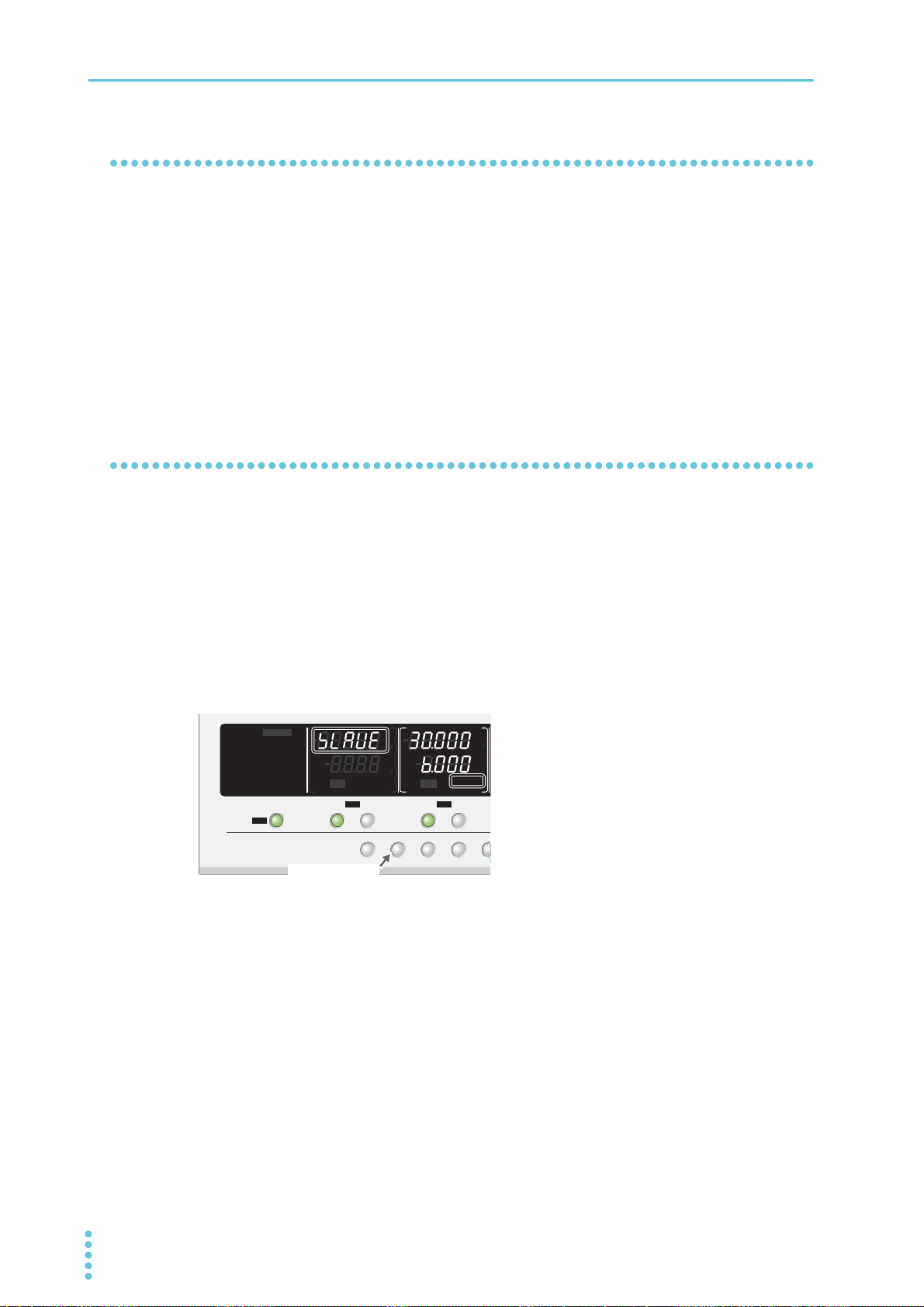
Parallel Operation and Series Operation | Overview of Parallel Operation
TRACK DELAY
ALM
C
DELAY SETTRACK SET
PRLSER
S
E
SELECTOUTPUT
CH1
SELECTOUTPUT
CH2
OUTPUT
ALL
CV
V
s
OFF
CC
A
s
ON
PRLSER
TRACKING 12
LOCK
REMOTE
LAN LAN
DEL AY
DEL AY SET
SET OVP࣭OCP
PRESET A BC
ALARM
CV
V
s
OFF
CC
A
s
ON
PRLSER
TRACKING 12
%%
%%
SHIFT+PRL key
Configuration for parallel operation
Setting the voltage and current
Set the voltage and current on CH2 (master). The current can be set up to double the current that is possible when operating independently.
Setting the overvoltage protection (OVP) and overcurrent protection (OCP)
Set the overvoltage protection (OVP) and overcurrent protection (OCP) on CH2 (master) (p.38 , p.39 ).
Starting parallel operation
Turning on the POWER switch
Parallel operation cannot be used when the tracking function is enabled. Disable the tracking function.
Turn on the POWER switch of this product.
1
Press SHIFT+PRL to switch to parallel operation mode.
2
The CH1 voltmeter shows “SLAVE,” and the CH2 display area shows “PRL.”
Switching is possible only when the output is off.
Press SELECT on CH2.
3
CH2 is indicated with brackets.
Turn the VOLTAGE knob to set the voltage and the CURRENT knob to set the cur-
4
rent.
The CH2 display area shows the voltage and current.
Press OUTPUT on CH2 to turn output on.
5
70 User’s Manual PMX_MULTI
Page 71

Parallel Operation and Series Operation | Overview of Parallel Operation
CAUTION
Turning the POWER switch off
If you want to turn the POWER switch back on, wait at least 10 seconds after the panel display turns off. Repeatedly turning the POWER switch on and off at short intervals will shorten
the service life of the POWER switch and the internal input fuse.
Press OUTPUT on CH2 or OUTPUT ALL to turn output off.
1
Press SHIFT+PRL to disable the parallel operation mode.
2
“SLAVE” disappears from the CH1 voltmeter and “PRL” from the CH2 display area.
Turn the POWER switch off.
3
PMX_MULTI User’s Manual 71
Page 72
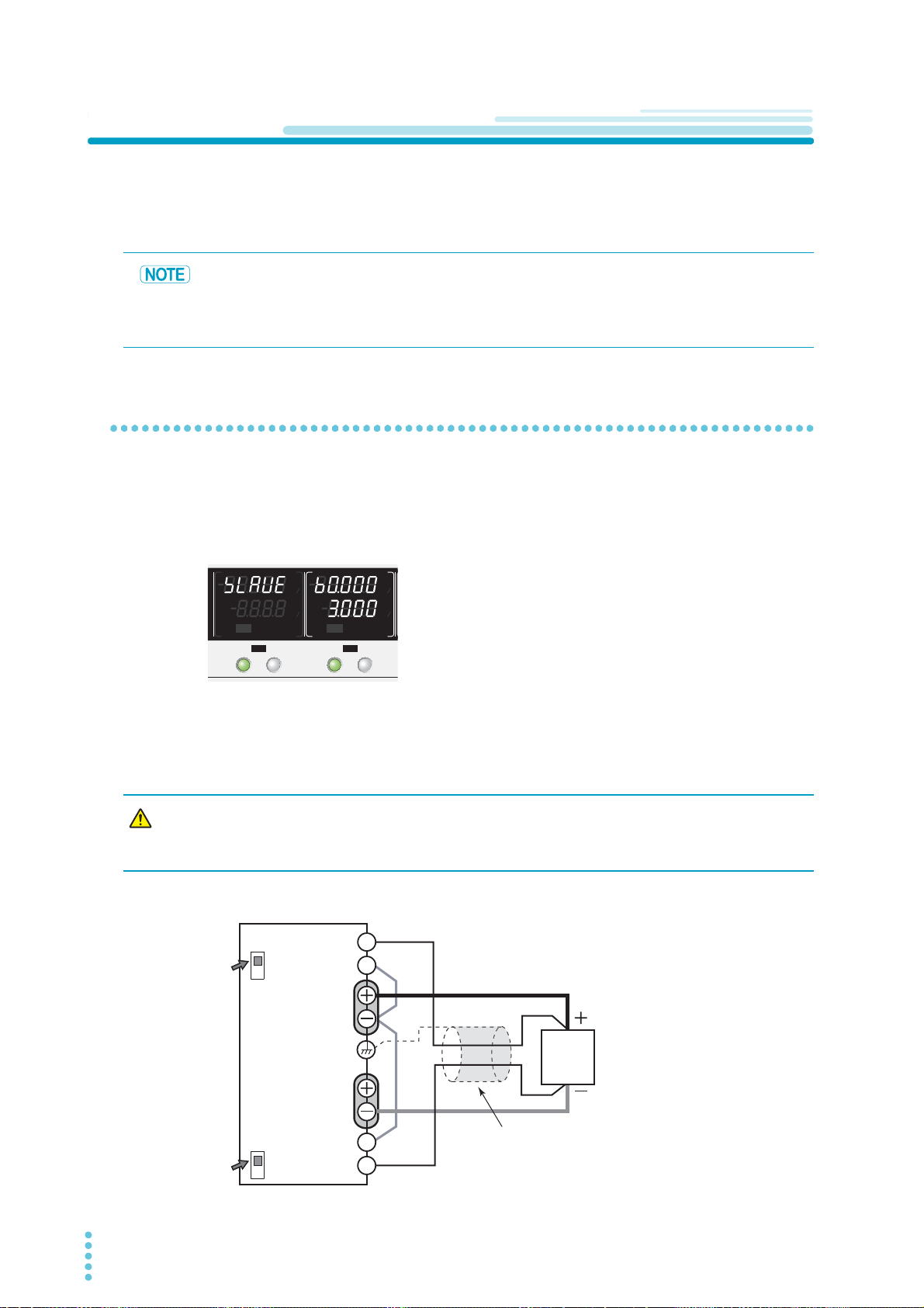
Parallel Operation and Series Operation
Panel display during series operation
Example when the output voltage is 60 V (CH1: 30 V+CH2: 30 V)
and the output current is 3 A
SELECTOUTPUT
CH1
SELECTOUTPUT
CH2
CV
V
s
OFF
CC
A
s
ON
PRLSER
TRACKING 12
CV
V
s
OFF
CC
A
s
ON
PRLSER
TRACKING 12
%%
%%
CAUTION
+
+S
-S
+S
-S
Sensing switch
Sensing switch
PMX
Load
Shielded cable
ON position
ON position
OFF
ON
OFF
ON
Output terminal
CH2 (master)
Output terminal
CH1 (slave)
Connection for using remote sensing
during series operation
Overview of Series Operation
CH1 and CH2 can be connected in series inside the product to double the voltage output range. CH2 operates as the master channel and CH1 as the slave channel.
In series operation, the output voltage is the total of the CH1 and CH2 outputs.
The specifications of this product are defined with the premise that CH1 and CH2 are connected in series internally. When used as positive and negative power supplies, the specifications may not be met.
The current limit of the CH1 output terminal and that of CH2 (master) are different.
Series operation functions
Voltage display and current display
The voltage or current is displayed on CH2 (master). The voltage is the total voltage of CH1 and CH2. The
CH1 voltmeter shows “SLAVE.”
Remote sensing
This is available (p.23).
The wiring for sensing is complicated when using remote sensing during series operation.
Be careful to wire the cables correctly. Incorrect wiring can cause abnormal voltage output or
damage to the product.
72 User’s Manual PMX_MULTI
Page 73

Parallel Operation and Series Operation | Overview of Series Operation
Memory
This is available (p.52).
The values set on CH2 (master) during series operation can be saved and recalled.
For the other channels of PMX32-3TR/PMX32-2QU, the values are shared between normal operation,
parallel operation, and series operation.
External control
This is available (p.60).
To perform output on/off control, use pin 9 (CH2) and pin 13. Open pin 8 (CH1).
Alarms
Alarms that are detected on a channel are also detected during series operation (p.37).
Clearing alarms
After resolving the cause of the alarm, press ALM CLR (SHIFT+SET), or turn the POWER switch off and
then on. If you do not resolve the cause of the alarm, an alarm will occur again.
If an alarm still occurs even after you have resolved all the causes of alarms, the product may be malfunctioning. Stop using it immediately, and contact your Kikusui agent or distributor.
PMX_MULTI User’s Manual 73
Page 74
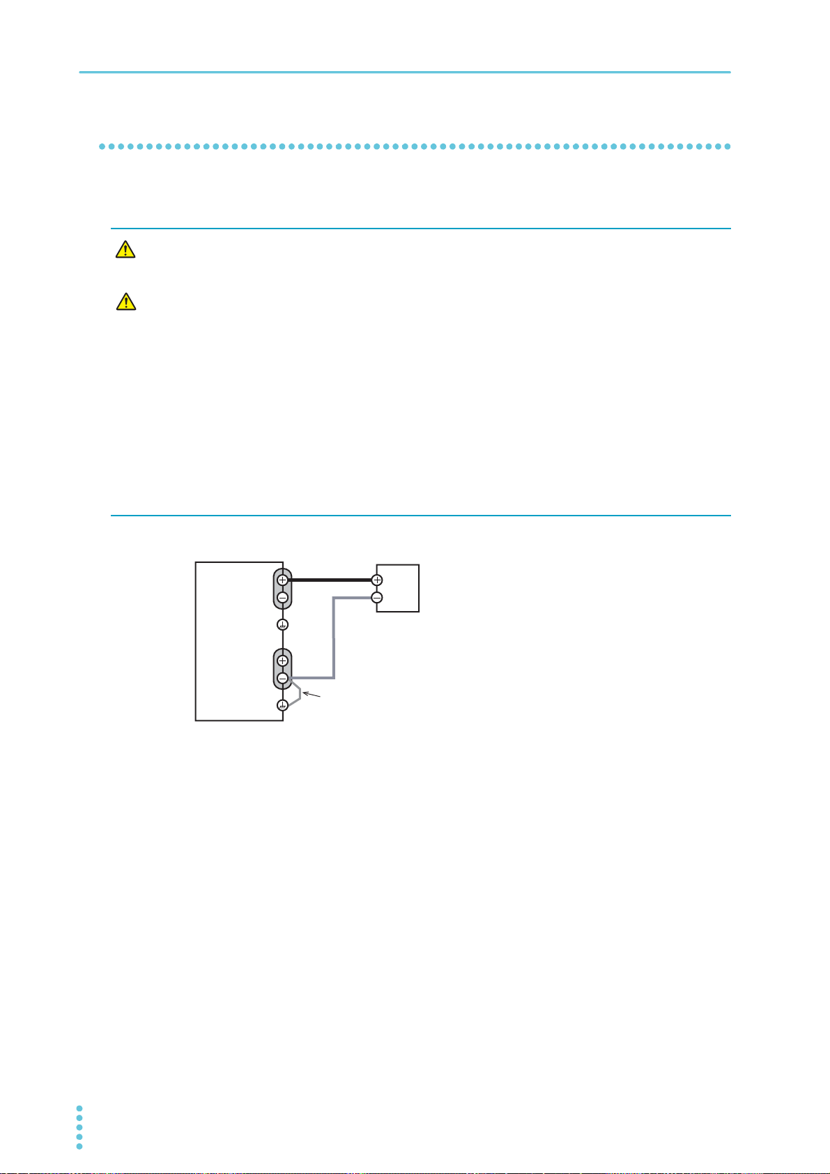
Parallel Operation and Series Operation | Overview of Series Operation
WARNING
CAUTION
Load or
relay terminal block
PMX
Output terminal
CH2
Output terminal
CH1
Chassis
terminal
Connect the negative terminal of CH1 or the
positive terminal of CH2 to the chassis terminal.
Load connection for series operation (CH1 and CH2)
Example of connecting the negative terminal of CH1 to the
chassis terminal
Connection for series operation
Connecting the Load
Risk of electric shock. Turn the POWER switch off before you touch the output terminals. Attach the output terminal cover after you finish wiring the load.
Risk of damage.
• If you are connecting the output terminal to the chassis terminal, connect the negative terminal of CH1 or the positive terminal of CH2 to the chassis terminal.
• The output terminals of CH1 and CH2 will output about half the specified output voltage (at
no load). Connecting in a manner different from the figure below can offset the balance
between the CH1 and CH2 output voltages and may damage the product.
• To prevent oscillation, connect an electrolytic capacitor with a capacitance of a few hundred µF to a few ten thousand µF across the load as necessary. If the wires are long, the
wiring inductance and capacitance can cause phase shifting at a level that can not be
ignored. This may lead to oscillation.
Use an electrolytic capacitor that has a withstand voltage that is at least 120 % of the rated
output voltage.
Turn the POWER switch off.
1
Connect the load cables (p.16) to the CH1 and CH2 output terminals.
2
Connect the load cables of CH1 and CH2 to the load.
3
Use load cables that have sufficient current capacity. If you are connecting to a relay terminal
block, use wires with the same length and cross-sectional area, and wire them as short as possible
(50 cm or less). If the voltage drop in the load cable is large, the difference in electric potential and
the load regulation become large.
Connect the negative terminal of CH1 or the positive terminal of CH2 to the chassis
4
terminal with a short bar.
Ground the output terminal of only one of the channels. Do not ground the output terminals of both
74 User’s Manual PMX_MULTI
channels.
Do not connect the positive terminal of CH1 or the negative terminal of CH2 to the chassis terminal.
Attach the output terminal cover.
5
This completes the connections.
Page 75
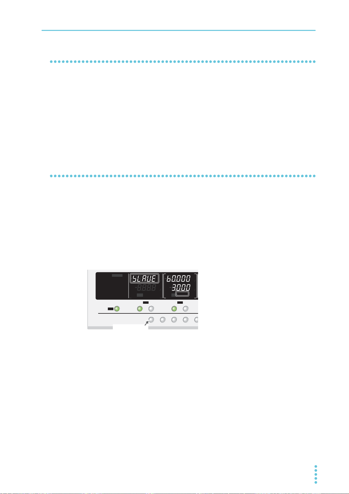
Parallel Operation and Series Operation | Overview of Series Operation
TRACK DELAY
ALM
C
DELAY SETTRACK SET
PRLSER
S
E
SELECTOUTPUT
CH1
SELECTOUTPUT
CH2
OUTPUT
ALL
CV
V
s
OFF
CC
A
s
ON
PRLSER
TRACKING 12
LOCK
REMOTE
LAN LAN
DEL AY
DEL AY SET
SET OVP・OCP
PRESET A BC
ALARM
CV
V
s
OFF
CC
A
s
ON
PALSER
TRACKING 12
%%
%%
SHIFT+SER key
Configuration for series operation
Setting the voltage and current
Set the voltage and current on CH2 (master). The voltage can be set up to double the voltage that is possible when operating independently.
Setting the overvoltage protection (OVP) and overcurrent protection (OCP)
Set the overvoltage protection (OVP) and overcurrent protection (OCP) on CH2 (master) (p.38 , p.39 ).
Starting series operation
Turning on the POWER switch
Series operation cannot be used when the tracking function is enabled. Disable the tracking function.
Turn on the POWER switch of this product.
1
Press SHIFT+SER to switch to series operation mode.
2
The CH1 voltmeter shows “SLAVE,” and the CH2 display area shows “SER.”
Switching is possible only when the output is off.
Press SELECT on CH2.
3
CH2 is indicated with brackets.
Turn the VOLTAGE knob to set the voltage and the CURRENT knob to set the cur-
4
rent.
The CH2 display area shows the voltage and current.
Press OUTPUT on CH2 to turn output on.
5
PMX_MULTI User’s Manual 75
Page 76

Parallel Operation and Series Operation | Overview of Series Operation
CAUTION
Turning the POWER switch off
If you want to turn the POWER switch back on, wait at least 10 seconds after the panel display turns off. Repeatedly turning the POWER switch on and off at short intervals will shorten
the service life of the POWER switch and the internal input fuse.
Press OUTPUT on CH2 or OUTPUT ALL to turn output off.
1
Press SHIFT+SER to disable the series operation mode.
2
“SLAVE” disappears from the CH1 voltmeter and “SER” from the CH2 display area.
Turn the POWER switch off.
3
76 User’s Manual PMX_MULTI
Page 77
Maintenance
The product is calibrated before shipment. We recommend periodic calibration to maintain the performance over an extended period.
For calibration, we recommend that you ask your Kikusui agent or distributor.
If you want to calibrate the product yourself, follow the procedure below.
Calibration overview
There are 14 calibration parameters.
Calibration is performed for 1 % and 100 % of full scale.
Voltage Current
Output voltage offset (1 % of the rated voltage) Output current offset (1 % of the rated current)
Output voltage full scale (100 % of the rated voltage) Output current full scale (100 % of the rated current)
Voltmeter offset (1 % of the rated voltage) Ammeter offset (1 % of the rated current)
Voltmeter full scale (100 % of the rated voltage) Ammeter full scale (100 % of the rated current)
Overvoltage protection (OVP) Overcurrent protection (OCP)
Output voltage offset in series operation (1 % of the
rated voltage)
Output voltage full scale in series operation (100 % of
the rated voltage)
Output current offset in parallel operation (1 % of the
rated current)
Output current full scale in parallel operation (100 %
of the rated current)
Test Equipment Required
• A DC voltmeter (DVM) with a measurement accuracy of 0.01 % or better
• A shunt resistor with an accuracy of 0.1 % or better, or an ammeter that can supply the rated output
current of the product to be calibrated
Environment
Perform calibration under the following environment.
• Temperature: 23 °C ± 5 °C
• Humidity: 80 %rh or less
To minimize the calibration error due to initial drift, warm up the product (with the current running) for at
least 30 minutes before calibration. In addition, warm up the DVM and shunt resistor for as long as is necessary.
PMX_MULTI User’s Manual 77
Page 78
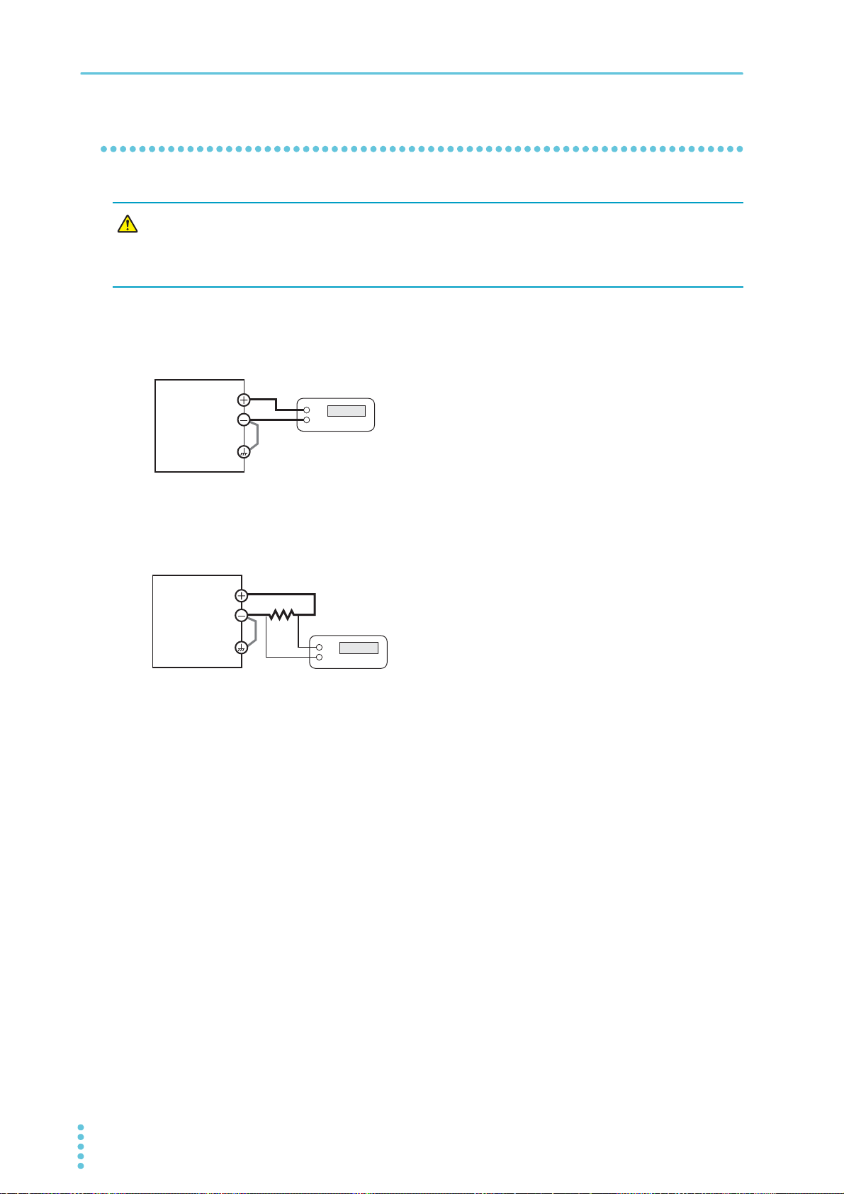
Maintenance
WARNING
DVM
PMX
HI
LO
Output terminal
Chassis terminal
Shunt or ammeter
DVM
HI
LO
Output terminal
Chassis terminal
Connection
Connection for voltage calibration
Risk of electric shock.
• Turn the POWER switch off before you touch the output terminals.
• Connect the output terminal to the chassis terminal.
Turn the POWER switch off.
1
Connect a DVM to the output terminals.
2
Connection for current calibration
PMX
Turn the POWER switch off.
1
Connect a shunt or ammeter to the output ter-
2
minals, and connect a DVM across it.
78 User’s Manual PMX_MULTI
Page 79
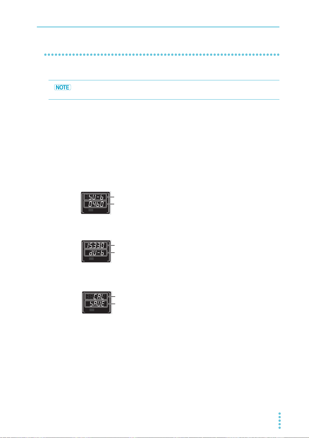
Calibration procedure
CV
V
s
OFF
CC
A
s
ON
PARASERI
TRACKING 12
%
%
Calibration
parameter
Calibration
data
CV
V
s
OFF
CC
A
s
ON
PARASERI
TRACKING 12
%
%
parameter
data
CV
V
s
OFF
CC
A
s
ON
PARASERI
TRACKING 12
%
%
Saving
calibration
information
Calibration
Example of a voltmeter
calibration display
Display for saving the
calibration information
(blinking)
Calibrate each channel.
The offset and full scale values affect all calibration parameters.
Be sure to calibrate both the offset and full scale values.
While holding down SET and LOCAL, turn the POWER switch on.
1
The product starts in calibration mode.
The voltmeter displays the calibration parameter, and the ammeter displays the calibration data.
Only during voltmeter calibration, the voltmeter displays the calibration data and the ammeter the
calibration parameter.
Press SELECT to select the channel you want to calibrate.
2
Calibrate by following the procedure for each calibration parameter.
3
You can change the resolution of the CURRENT knob (p.28).
Maintenance
Calibration
Calibration
SV-B(p.80) Output voltage offset
▼
SV-T(p.80) Output voltage full scale
▼
SC-B(p.81) Output current offset
▼
SC-T(p.81) Output current full scale
▼
DV-B(p.80) Voltmeter offset
▼
DV-T(p.80) Voltmeter full scale
▼
DC-B(p.81) Ammeter offset
▼
DC-T(p.81) Ammeter full scale
▼
OVPC(p.80) Overvoltage protection
(OVP)
▼
OCPC(p.81) Overcurrent protection
(OCP)
PMX_MULTI User’s Manual 79
Press SET to make “CAL” blink on the voltmeter and “SAVE” blink on the ammeter.
4
To save the calibration data, press SET again.
5
Otherwise, press LOCK.
The blinking stops, and the product returns to calibration mode.
To finish calibration, turn off the POWER switch.
6
Page 80
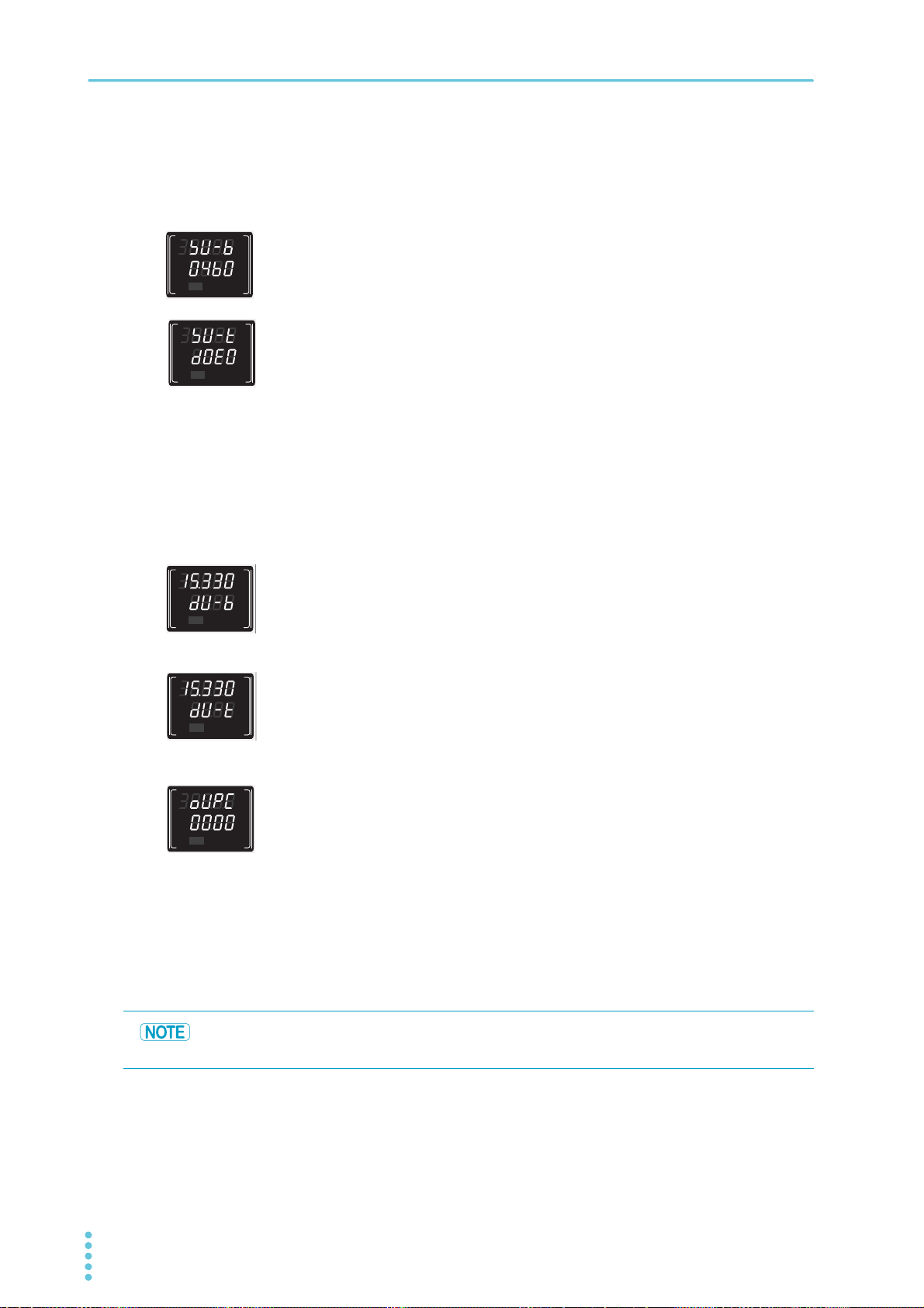
Maintenance
CV
V
s
OFF
CC
A
s
ON
PARASERI
TRACKING 12
%
%
CV
V
s
OFF
CC
A
s
ON
PARASERI
TRACKING 12
%
%
CV
V
s
OFF
CC
A
s
ON
PARASERI
TRACKING 12
%
%
CV
V
s
OFF
CC
A
s
ON
PARASERI
TRACKING 12
%
%
CV
V
s
OFF
CC
A
s
ON
PARASERI
TRACKING 12
%
%
Output voltage calibration (offset and full scale)
Voltmeter calibration (offset, full scale, and OVP)
Be sure to calibrate the output voltage before calibrating the voltmeter.
Press SELECT to select the channel you want to calibrate.
1
Use the VOLTAGE knob to select SV-B, and turn on the output.
2
Turn the CURRENT knob to set the DVM reading to 1 % of the rated
3
output voltage.
Use the VOLTAGE knob to select SV-T, and turn on the output.
4
Turn the CURRENT knob to set the DVM reading to 100 % of the rated
5
output voltage.
Press SELECT to select the channel you want to calibrate.
1
Use the VOLTAGE knob to select DV-B, and turn on the output.
2
Turn the CURRENT knob to match the product’s voltage reading to the
3
DVM reading.
Use the VOLTAGE knob to select DV-T, and turn on the output.
4
Turn the CURRENT knob to match the product’s voltage reading to the
5
DVM reading.
Turn the VOLTAGE knob to select OVPC.
6
Press OVP•OCP.
7
Calibration is performed automatically. The voltmeter and ammeter displays change
during this process.
If the calibration completes successfully, the ammeter displays
8
“DONE.”
If it doesn’t, the ammeter displays “FAIL.”
If the calibration ends with any other display, contact your Kikusui agent or distributor.
If you press OUTPUT ALL during the calibration, the OVP calibration ends, and the ammeter
displays “FAIL.”
80 User’s Manual PMX_MULTI
Page 81
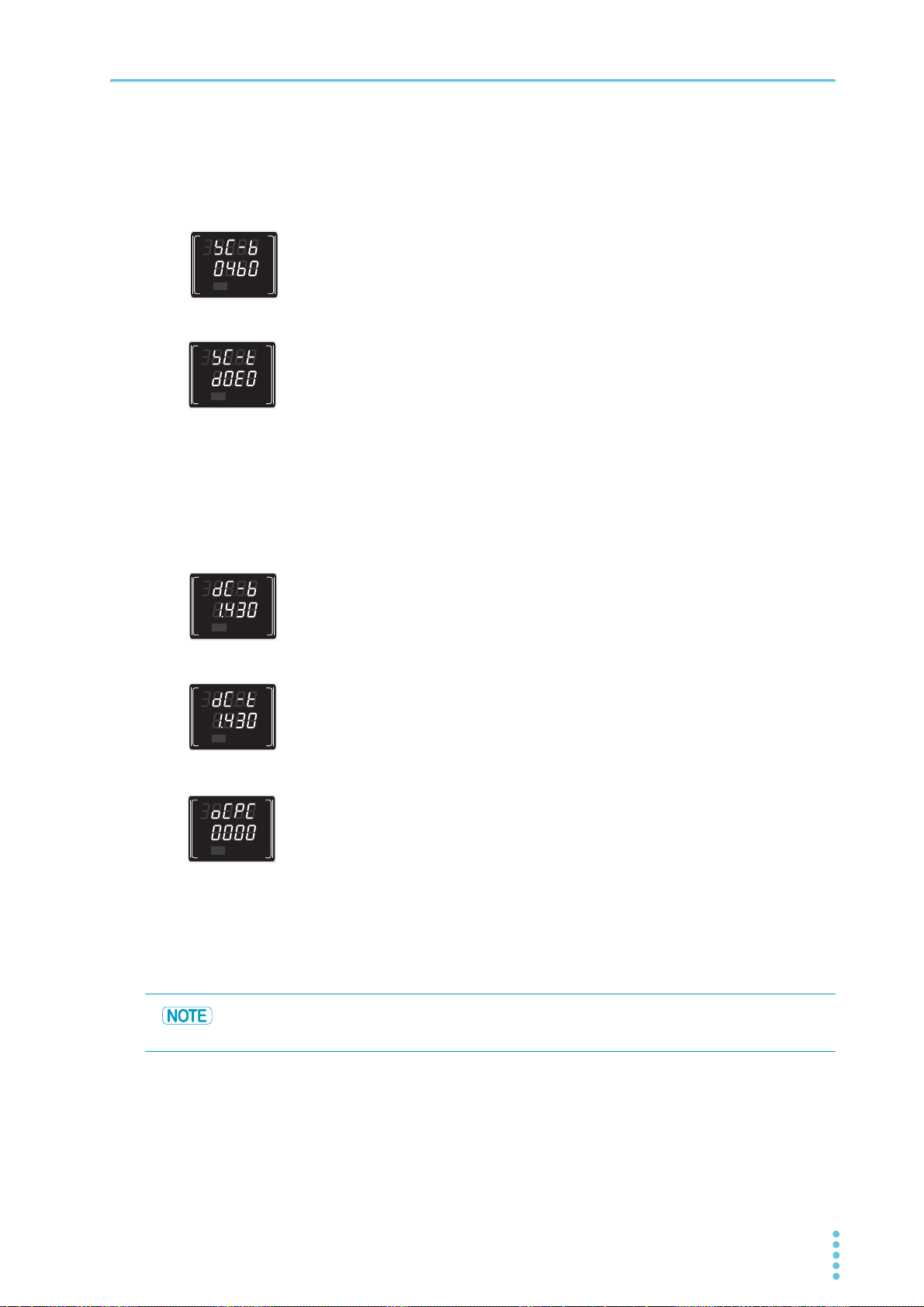
Output current calibration (offset and full scale)
CV
V
s
OFF
CC
A
s
ON
PARASERI
TRACKING 12
%
%
CV
V
s
OFF
CC
A
s
ON
PARASERI
TRACKING 12
%
%
CV
V
s
OFF
CC
A
s
ON
PARASERI
TRACKING 12
%
%
CV
V
s
OFF
CC
A
s
ON
PARASERI
TRACKING 12
%
%
CV
V
s
OFF
CC
A
s
ON
PARASERI
TRACKING 12
%
%
Press SELECT to select the channel you want to calibrate.
1
Use the VOLTAGE knob to select SC-B, and turn on the output.
2
Turn the CURRENT knob to set the DVM reading (converted current
3
value) to 1 % of the rated output current.
Use the VOLTAGE knob to select SC-T, and turn on the output.
4
Turn the CURRENT knob to set the DVM reading (converted current
5
value) to 100 % of the rated output current.
Ammeter calibration (offset, full scale, and OCP)
Be sure to calibrate the output current before calibrating the ammeter.
Maintenance
Press SELECT to select the channel you want to calibrate.
1
Use the VOLTAGE knob to select DC-B, and turn on the output.
2
Turn the CURRENT knob to match the product’s current reading to the
3
DVM reading.
Use the VOLTAGE knob to select DC-T, and turn on the output.
4
Turn the CURRENT knob to match the product’s current reading to the
5
DVM reading (converted current value).
Turn the VOLTAGE knob to select OCPC.
6
Press OVP•OCP.
7
Calibration is performed automatically. The voltmeter and ammeter displays change
during this process.
If the calibration completes successfully, the ammeter displays
8
“DONE.”
If it doesn’t, the ammeter displays “FAIL.”
If the calibration ends with any other display, contact your Kikusui agent or distributor.
If you press OUTPUT ALL during the calibration, the OCP calibration ends, and the ammeter
displays “FAIL.”
PMX_MULTI User’s Manual 81
Page 82
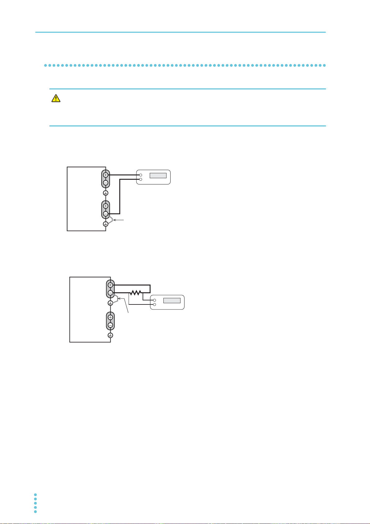
Maintenance
WARNING
PMX
Output terminal
CH2
Output terminal
CH1
Chassis terminal
Connect the negative terminal
of CH1 or the positive terminal
of CH2 to the chassis terminal.
DVM
HI
LO
HI
LO
PMX
Output terminal
CH2
Chassis terminal
Output terminal
CH1
Chassis terminal
Shunt or ammeter
DVM
Connect the output terminal
of one of the channels to the
chassis terminal.
Connection (series operation and parallel operation)
Risk of electric shock.
• Turn the POWER switch off before you touch the output terminals.
• Connect the output terminal to the chassis terminal.
Connection for voltage calibration (for series operation)
Turn the POWER switch off.
1
Connect a DVM to the output terminals.
2
Connection for current calibration (for parallel operation)
Turn the POWER switch off.
1
Connect a shunt or ammeter to the out-
2
put terminals, and connect a DVM
across it.
82 User’s Manual PMX_MULTI
Page 83
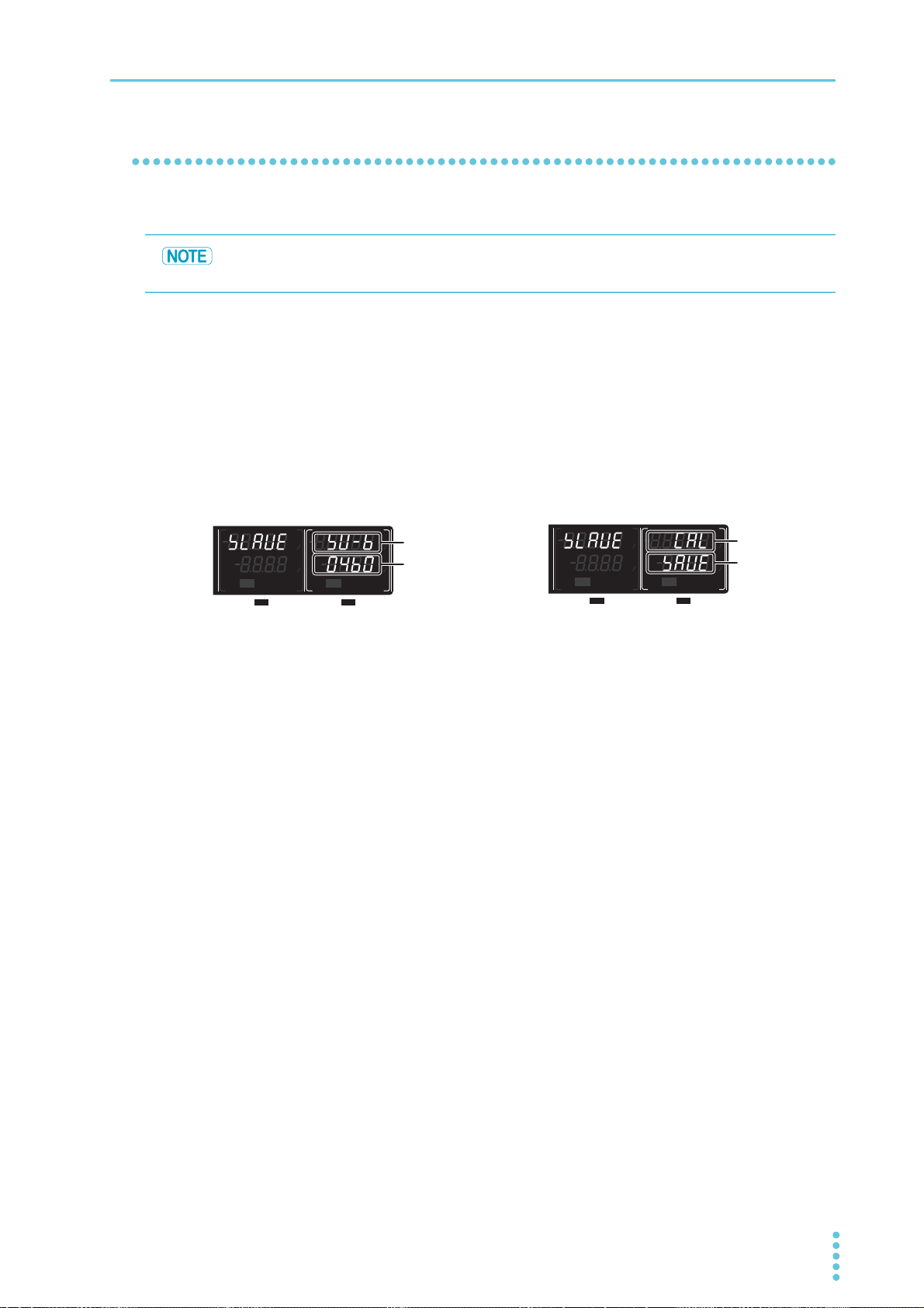
Maintenance
SELECTOUTPUT
CH1
SELECTOUTPUT
CH2
CV
V
s
OFF
CC
A
s
ON
PARASERI
TRACKING 12
CV
V
s
OFF
CC
A
s
ON
PARASERI
TRACKING 12
%%
%%
Calibration parameter
Calibration data
Output voltage offset display (for series operation)
SELECTOUTPUT
CH1
SELECTOUTPUT
CH2
CV
V
s
OFF
CC
A
s
ON
PRLSER
TRACKING 12
CV
V
s
OFF
CC
A
s
ON
PRLSER
TRACKING 12
OFF
%%
%%
data
Calibration
Display for saving calibration data (blinking)
Calibration procedure (series operation and parallel operation)
Calibrate CH2 (master).
The offset and full scale values affect all calibration parameters.
Be sure to calibrate both the offset and full scale values.
While holding down SET and LOCAL, turn the POWER switch on.
1
The product starts in calibration mode.
The voltmeter displays the calibration parameter, and the ammeter displays the calibration data.
To select voltage calibration for series operation, press SHIFT+SER. To select cur-
2
rent calibration for parallel operation, press SHIFT+PRL.
Calibrate by following the procedure for each calibration parameter.
3
You can change the resolution of the CURRENT knob (p.28).
Press SHIFT+SER or SHIFT+PRL to return to the calibration screen for normal
4
operation.
Press SET to make “CAL” blink on the CH2 voltmeter and “SAVE” blink on the
5
ammeter.
To save the calibration data, press SET again.
6
Otherwise, press LOCK.
The blinking stops, and the product returns to calibration screen.
To finish calibration, turn off the POWER switch.
7
Saving calibration
PMX_MULTI User’s Manual 83
Page 84

Maintenance
Voltage calibration for series operation (offset and full scale)
1
2
3
4
Current calibration for parallel operation (offset and full scale)
1
2
Use the VOLTAGE knob to select SV-B, and turn on the CH2 output.
Turn the CURRENT knob to set the DVM reading to 1 % of the rated output voltage.
Use the VOLTAGE knob to select SV-T, and turn on the CH2 output.
Turn the CURRENT knob to set the DVM reading to 100 % of the rated output voltage.
Use the VOLTAGEob to select SC-B, and turn on the CH2 output.
Turn the CURRENT knob to set the DVM reading (converted current value) to 1 % of
the rated output current. kn
Use the VOLTAGE knob to select SC-T, and turn on the CH2 output.
3
Turn the CURRENT knob to set the DVM reading (converted current value) to 100 %
4
of the rated output current.
84 User’s Manual PMX_MULTI
Page 85
Specifications
Unless specified otherwise, the specifications are for the following settings and conditions.
• Loads are purely resistive loads.
• The product is warmed up for at least 30 minutes.
• The negative output is connected to the chassis terminal with a short bar.
• Values indicated by “TYP” are typical values. These values do not guarantee the performance of the
PMX seres (multiple-output).
• rating: Indicates the rated.
• set: Indicates a setting.
• reading: Indicates the readout value.
• Rated load and no load are defined as follows:
In constant-voltage mode (when the output current is set to a value greater than or equal to the maxi-
mum output current with rated output voltage)
Rated load: Refers to a resistive load that, when the rated output voltage is applied, makes the
flowing current 95 % to 100 % of the maximum output current with rated output volt-
age.
No load: Refers to a load through which no output current flows. In other words, refers to an
open load (no load being connected).
In constant-current mode (when the output voltage is set to a value greater than or equal to the maximum output voltage with rated output current)
Rated load: Refers to a resistive load that, when the rated output current flows, makes the voltage
drop to 95 % to 100 % of the maximum output voltage with rated output current.
Including the voltage drop in the load cables, the product’s output voltage must not
exceed the maximum output voltage with rated output current.
AC input
Nominal input rating
Input voltage range ± 10 %
Input frequency range 47 Hz to 63 Hz
Inrush current (MAX)
Power (MAX) 700 VA 900 VA 800 VA
*1. 100 Vac, 117 Vac, 200 Vac, and 234 Vac are factory options.
*2. Excludes the charge current component that flows through the capacitor of the internal EMC
No load: Refers to a resistive load that, when the rated output current flows, makes the voltage
drop to 10 % of the maximum output voltage with rated output current or 1 V whichever
is higher.
PMX32-3DU PMX32-3TR PMX32-2QU
217 Vac
*2
150 A 150 A 150 A
filter circuit immediately after the POWER switch is turned on (for approximately 1 ms).
*1
, 50 Hz/ 60 Hz, single phase
PMX_MULTI User’s Manual 85
Page 86
Specifications
Output
PMX32-3DU PMX32-3TR PMX32-2QU
Rating Output voltage CH1 32.000 V 32.000 V 32.000 V
CH2 32.000 V 32.000 V 32.000 V
CH3 — 6.000 V 18.000 V
CH4 — — 18.000 V
Output current CH1 3.000 A 3.000 A 2.000 A
CH2 3.000 A 3.000 A 2.000 A
CH3 — 5.000 A 2.500 A
CH4 — — 2.500 A
Constant
voltage
Maximum
voltage setting
Resolution 1 mV
Voltage setting accuracy
Input line
regulation
Load regula-
*3
tion
Transient response
Ripple noise (rms)
Command delay 80 ms
Rise time (at rated load)
Fall time
(at no load)
Temperature coefficient
(TYP)
CH1 33.600 V 33.600 V 33.600 V
CH2 33.600 V 33.600 V 33.600 V
CH3 — 6.300 V 18.900 V
CH4 — — 18.900 V
*1
±(0.03 % set +5 mV)
CH1 3 mV 3 mV 3 mV
*2
CH2 3 mV 3 mV 3 mV
CH3 — 1 mV 1 mV
CH4 — — 1 mV
CH1 4 mV 4 mV 2 mV
CH2 4 mV 4 mV 2 mV
CH3 — 5 mV 3 mV
CH4 — — 3 mV
*4
*5
CH1 350 ms ±30 % 350 ms ±30 % 350 ms ±30 %
*7
CH2 350 ms ±30 % 350 ms ±30 % 350 ms ±30 %
CH3 — 220 ms ±30 % 240 ms ±30 %
CH4 — — 240 ms ±30 %
*6
50 μs
500 μV
10 ms ±30 %
100 ppm/ °C
86 User’s Manual PMX_MULTI
Page 87
Specifications
PMX32-3DU PMX32-3TR PMX32-2QU
constant
current
*1. At an ambient temperature of 23 °C±5 °C.
*2. 90 % to 100 % or 100 % to 110 % of the nominal input voltage rating, rated load.
*3. The amount of change that occurs when the load is changed from no load to rated load at the rated
*4. The amount of time required for the output voltage to return to a value within "rated output voltage ±
*5. When the measurement frequency bandwidth is 5 Hz to 1 MHz.
*6. The time for the output voltage to rise from 10 % to 90 % of the rating when the output is turned on.
*7. The time for the output voltage to fall from 90 % to 10 % of the rating when the output is turned off.
*8. The amount of current change when the load is changed from 10 % of the rated voltage or 1 V,
Maximum
current setting
CH1 3.150 A 3.150 A 2.100 A
CH2 3.150 A 3.150 A 2.100 A
CH3 — 5.250 A 2.625 A
CH4 — — 2.625 A
Resolution 0.1 mA
*1
Current setting accuracy
Input line regulation
Load regulation
Ripple noise
*5
(rms)
*2
*8
CH1 1 mA 1 mA 1 mA
CH2 1 mA 1 mA 1 mA
±(0.3 % set +0.1 % rating)
0.01 % + 0.25 mA
5mA
CH3 — 2 mA 1 mA
CH4 — — 1 mA
Temperature coefficient
200 ppm/ °C
(TYP)
output voltage. The value is measured at the sensing point.
(0.05 % + 10 mV)." When the load current is changed from 10 % to 100 % of the rated output current. The value is measured at the sensing point.
whichever is higher, to the rated voltage at rated output current.
PMX_MULTI User’s Manual 87
Page 88
Specifications
Display function
Voltmeter Maximum display 99.999 (fixed decimal point)
Ammeter Maximum display 9.999 (fixed decimal point)
Operation
display
*1. At an ambient temperature of 23 °C±5 °C.
PMX32-3DU PMX32-3TR PMX32-2QU
Display accuracy
Display accuracy
OUTPUT ON/OFF Output on: “ON” display (green)
Output-on delay/ off delay Displays “DELAY SET” when set.
CV operation “CV” display (green)
CC operation “CC” display (red)
Alarm operation Displays “ALARM” (red) when a protection function is acti-
Memory Displays “PRESET A,” “PRESET B,” or “PRESET C” when
key lock Displays “LOCK” when the keys are locked.
Tracking Displays “TRACKING 1” or “TRACKING 2” when tracking is
Remote operation Displays “REMOTE” during remote control.
LAN operation Displays or blinks “LAN” (depending on the status).
*1
*1
±(0.1 % of reading +10 mV)
±(0.2 % of reading +5 mA)
Output off: “OFF” display
“DELAY” blinks during output-on delay/ off delay.
“DELAY” is displayed after the output-on delay/off delay has
passed.
vated.
a memory area is in use.
in operation.
• No fault status: Lights green.
• Fault status: Lights green.
• Standby status: Blinks red.
• WEB identify status: Blinks green.
88 User’s Manual PMX_MULTI
Page 89
Protection function
Overvoltage
protection (OVP)
Overcurrent
protection (OCP)
Overheat
protection (OHP)
Communication
monitorring
(WATCHDOG)
Alarm
signal input
(ALARM IN)
*1. This does not protect against the discharge current peak that is generated from the capacitors in-
side the product’s output section when the load is changed suddenly.
Action Turns the output off, displays “OVP,” and displays “ALARM” (red).
Setting range 10 % to 110 % of the rated output voltage
Setting
accuracy
Resolution 1 mV
Action
Setting range 10 % to 110 % of the rated output current
Setting
accuracy
Resolution 0.1 mA
Action Turns the output off, displays “OHP,” and displays “ALARM” (red).
Action Turns the output off, displays “WDOG,” and displays “ALARM”
Action Turns the output off, displays “IN,” and displays “ALARM” (red).
Specifications
PMX32-3DU PMX32-3TR PMX32-2QU
±(1 % of rating)
*1
Turns the output off, displays “OCP,” and displays “ALARM” (red).
±(1 % of rating)
(red).
Signal output
Status
Signal
*1
output
*1. Photocoupler open collector output;
Maximum voltage 30 V, maximum current (sink) 8 mA. Isolated from the output and control circuits. The status common is floating (within the isolation voltage).
Common specifications
OUTPUT ON STATUS On when output is on.
ALARM STATUS On when an alarm is activated (OVP, OCP, OHP,
WATCHDOG, ALARM IN).
POWER ON STATUS Turns on when the power is turned on
PMX_MULTI User’s Manual 89
Page 90
Specifications
Control functions
External
control
Sensing
Output on/off control
(OUTPUT ON/OFF CONT)
Alarm input
(ALARM IN)
Common specifications
Logic selectable:
• Negative logic
Output on when set to LOW (0 V to 0.5 V) or
shorted; output off when set to HIGH (4.5 V or
5 V) or open
• Positive logic
Output on when set to HIGH (4.5 V to 5 V) or
open; output off when set to LOW (0 V or 0.5 V) or
shorted
The output turns off with an alarm signal input (the
contact switch shorted for at least 0.5 s).
Common specifications
Sensing 0.6 V for a single line (but the output terminals are con-
trolled at the rated voltage)
90 User’s Manual PMX_MULTI
Page 91
Parallel operation and series operation
PMX32-3DU PMX32-3TR PMX32-2QU
Parallel operation
Applicable channels Master: CH2, slave: CH1
Constant
voltage
constant
current
Voltmeter Maximum
Ammeter Maximum
Series operation
Applicable channels Master: CH2, slave: CH1
Constant
voltage
constant
current
Voltmeter Maximum
Ammeter Maximum
*1. At an ambient temperature of 23 °C±5 °C.
*2. The value is measured at the sensing point.
Operating range 0 V to 32 V
Setting range 0 V to 33.6 V
*1
Setting accuracy
0.3 % set + 0.1 % rating
Resolution 1 mV
Operating range 0 A to 6 A 0 A to 4 A
Setting range 0 A to 6.3 A 0 A to 4.2 A
*1
Setting accuracy
0.4 % set + 0.1 % rating
Resolution 0.2 mA
99.999 (fixed decimal point)
display
Display
accuracy
*1
±(0.5 % of reading + 10 digit)
9.999 (fixed decimal point)
display
Display
accuracy
*1
±(1 % of reading + 10 digit)
Operating range 0 V to 64 V
Setting range 0 V to 67.2 V
*1, *2
Setting accuracy
0.3 % set + 0.1 % rating
Resolution 2 mV
Operating range 0 A to 3 A 0 A to 2 A
Setting range 0 A to 3.15 A 0 A to 2.1 A
*1
Setting accuracy
0.4 % set + 0.1 % rating
Resolution 0.1 mA
99.999 (fixed decimal point)
display
Display
accuracy
*1, *2
±(0.5 % of reading + 20 digit)
9.999 (fixed decimal point)
display
Display
accuracy
*1
±(1 % of reading + 5 digit)
Specifications
PMX_MULTI User’s Manual 91
Page 92

Specifications
Other functions
Output-on delay/ off delay
Applicable channels All channels
Setup Set the output on/off delay time.
Setting range 0.1 s to 99.9 s
Resolution 0.1 s
Setting accuracy
Memory Saves three combinations of voltage, current, OVP, OCP,
key lock Selectable from the following three modes.
Tracking
Applicable channels All channels
Operation
mode
Setting
accuracy
*1. The difference between the time from when the reference output reaches 50 % of the setting to
when the target output reaches 50 % of the setting and the delay time setting.
*2. In tracking function 1, the output can be varied within the output range of the reference channel
voltage or current.
*3. In tracking function 2, the output can be varied at the same percentage as the reference output in
reference to the output at the start of the tracking function.
Common specifications
*1
Tracking function 1
Tracking function 2
CV setting accuracy 0.4 % of rating + 40 mV
CC setting accuracy 0.7 % of rating + 10 mA
±50 ms
and output-on delay/ off delay settings.
• Loc1: Lock all keys except the OUTPUT and memory A,
B, and C keys.
• Loc2: Lock all keys except the OUTPUT key.
• Loc3: Lock all keys and the rotary knob.
*2
Absolute value change
*3
Percentage change
92 User’s Manual PMX_MULTI
Page 93
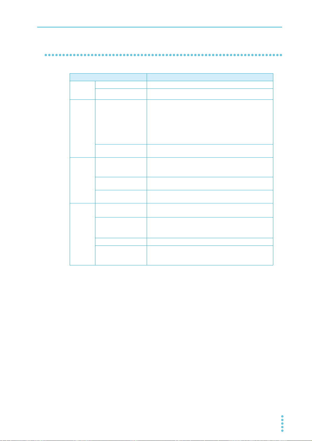
Interface
Item Common specifications
Common
specifications
RS232C Hardware Complies with the EIA232D specifications (excluding the termi-
USB Hardware Standard type B socket.
LAN Hardware IEEE 802,3 100Base-TX/10Base-T Ethernet
Specifications
Software protocol IEEE Std 488.2-1992
Command language Complies with SCPI Specification 1990.0
nal block)
D-sub 9-pin terminal block (male)
Baudrate: 1200, 2400, 4 800, 9600, 19 200, 38400, 57 600,
115200 bps
Data length: 8 bits, Stop bits: 1 bit, Parity bit: None
Flow control: No
Program message terminator
Program message terminator
Device class Complies with the USBTMC-USB488 device class specifica-
Compliant standards LXI Device Specification 2016
Communication protocol VXI-11, HiSLIP, SCPI-RAW, SCPI-Telnet
Message terminator VXI-11, HiSLIP: LF or END during reception, LF + END during
LF during reception, LF during transmission.
Complies with the USB 2.0 specifications; data rate: 12 Mbps
(full speed)
LF or EOM during reception, LF + EOM during transmission.
tions.
IPv4, RJ-45 terminal block
LXI HiSLIP Extended Function Rev. 1.0
LXI VXI-11 Extended Function Rev. 1.0
transmission.
SCPI-RAW: LF during reception, LF during transmission.
PMX_MULTI User’s Manual 93
Page 94
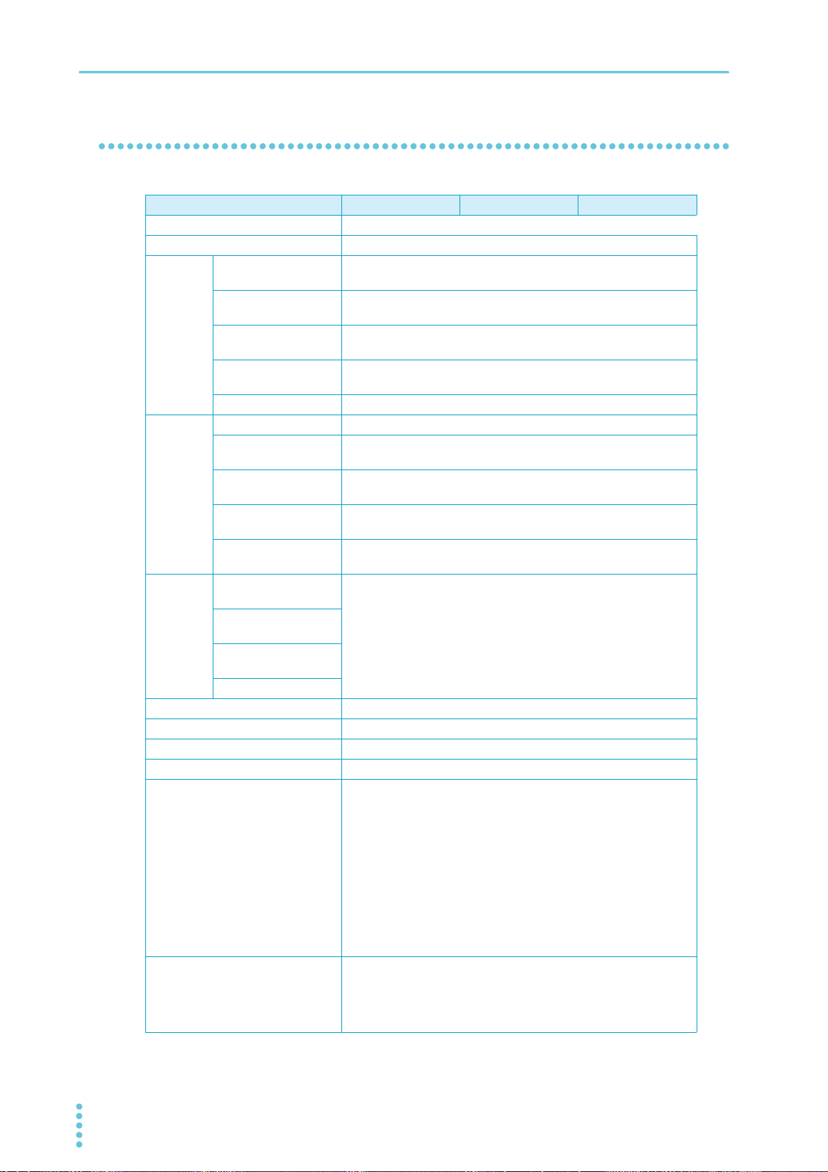
Specifications
General specifications
Item PMX32-3DU PMX32-3TR PMX32-2QU
Weight (main unit only) Approx. 13 kg (28.66 lb)
Dimensions See the outline drawing (p.95).
Environmental
conditions
Isolation
voltage
Withstanding voltage
Insulation
resistance
Cooling method Forced air cooling using a fan motor
Common All channels are independent.
Grounding polarity Negative grounding or positive grounding possible
Accessories See (p.3).
Electromagnetic compatibility
Safety
*1. Does not apply to specially ordered or modified products.
*2. Only on models that have the CE marking on the panel.
Operating temperature range
Operating humidity
range
Storage temperature
range:
Storage humidity
range:
Installation location Indoor use, altitude of up to 2 000 m, overvoltage category II
Between channels ±70 Vdc
Between the output
and chassis
Between the primary
circuit and chassis
Between the primary
and secondary circuits
Between the secondary circuit and chassis
Between the primary
circuit and chassis
Between the primary
and secondary circuits
Between the secondary circuit and chassis
Between channels
*1
*1*2
0 °C to 40 °C (32 °F to 104 °F)
20 %rh to 85 %rh (no condensation)
-25°C to 70°C (13°F to 158°F)
90 %rh or less (no condensation)
±70 Vdc
No abnormalities at 1500 Vac for 1 minute.
No abnormalities at 2600 Vac for 1 minute.
No abnormalities at 1500 Vdc for 1 minute.
500 Vdc, 30 MΩ or greater
Complies with the requirements of the following directive and standards.
EMC Directive 2014/30/EU
EN 61326-1 (Class A
EN 55011 (Class A
EN 61000-3-2
EN 61000-3-3
Applicable under the following conditions
The maximum length of all cabling and wiring connected to the
product must be less than 3 m.
Complies with the requirements of the following directive and standards.
EMC Directive 2014/35/EU
EN 61010-1 (Class I*5, Pollution Degree 2*6)
*3
)
*3
, Group 1*4)
*2
94 User’s Manual PMX_MULTI
Page 95
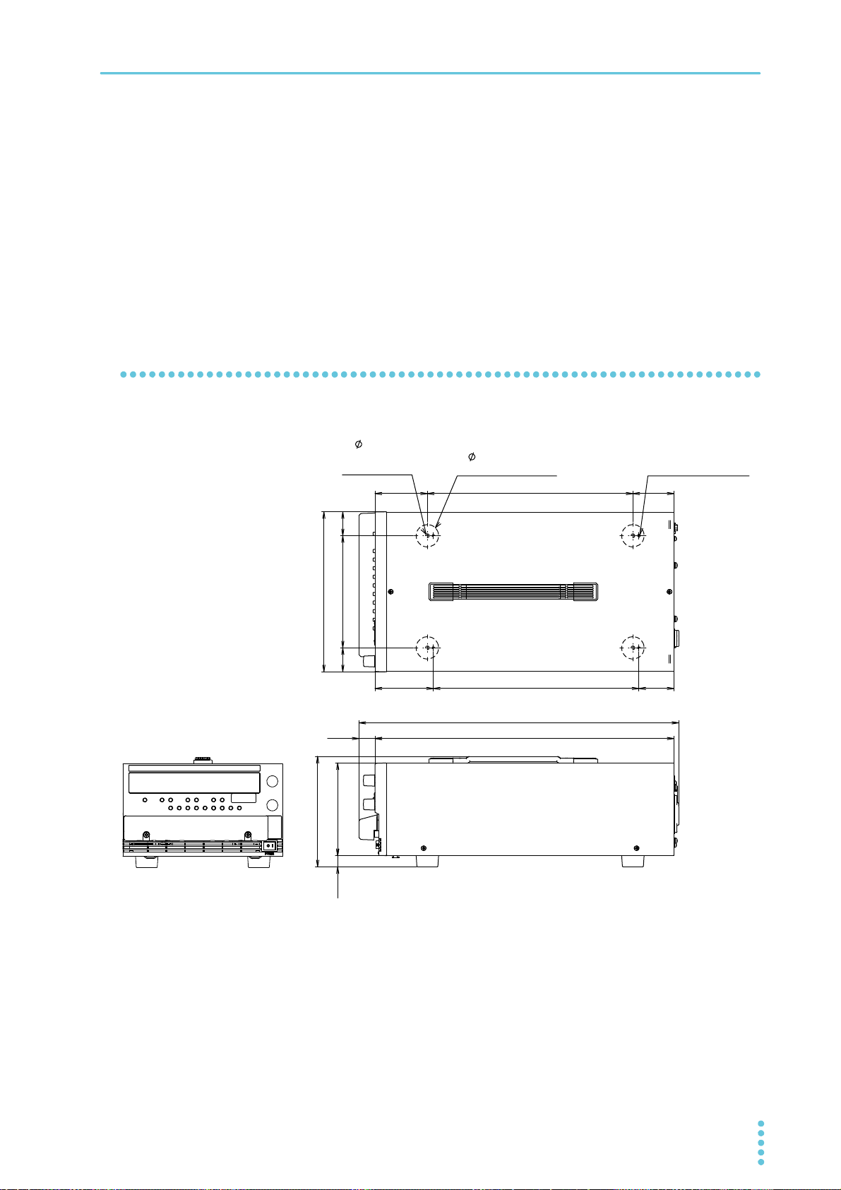
*3. This product confirms to Class A. This product is intended for use in an industrial environment. This
4-
5
(holes for attaching
the rubber feet)
4-
30
(rubber foot diameter)
depth: 6 mm)
214 (8.46)
70 (2.76)
275 (10.83)
55 (2.17)
32
(1.26)
150 (5.91)
32
(1.26)
78 (3.07)
275 (10.83 )
47 (1.85)
MAX 435 (17.13)
124 (4.88)
MAX 155 (6.10)
MAX 25
(0.98)
400 (15.75)
product may cause interference if used in residential areas. Such use must be avoided unless the user
takes special measures to reduce electromagnetic emissions to prevent interference to the reception
of radio and television broadcasts.
*4. This is a Group 1 instrument. This product does not generate and/or use intentionally radio-frequency
energy, in the form of electromagnetic radiation, inductive and/or capacitive coupling, for the treatment of material or inspection/analysis purpose.
*5. This product confirms to Class I. Be sure to ground the protective conductor terminal of this product.
If not grounded properly, safety is not guaranteed.
*6. Pollution is addition of foreign matter (solid, liquid or gaseous) that may produce a reduction of dielec-
tric strength or surface resistivity. Pollution Degree 2 assumes that only non-conductive pollution will
occur except for an occasional temporary conductivity caused by condensation.
External dimensions
Specifications
4-M4 screw holes
(max. screw insertion
MAX 20
(0.79)
PMX32-3DU/ PMX32-3TR/ PMX32-2QU External dimensions
Unit: mm (inches)
PMX_MULTI User’s Manual 95
Page 96
Appendix
Factory Default Settings
If you hold down LOCAL and LOCK and turn the POWER switch on, the product will be initialized to its factory default settings.
The voltmeter displays “INIT,” and the product is set to factory default settings.
Basic settings
Basic item Description
Output voltage 0 V
Output current Maximum settable current
OVP (overvoltage protection) 110 % of the rated output voltage
OCP (overcurrent protection) 110 % of the rated output current
Memory values A, B, C Output voltage, output current, OVP, OCP: Factory default settings
output-on delay/ off delay time: 0.0 s
CONFIG settings
Parameter
number
CF01 Output state at power-on SAFE (output off)
CF02 Memory content display ON (displayed)
CF03 Key lock content LOC3 (Lock all keys and the rotary knob)
CF04
CF05
CF06
CF07
CF08 Output state when a protection function
CF09
CF20 LAN interface ON (use)
CF21 USB interface ON (use)
CF22 RS232C interface ON (use)
CF23 SCPI communication error display OFF (not displayed)
CF24 Communication monitoring (watchdog) timer OFF (timer off)
CF25 Buzzer on/off ON (Buzzer on)
CF40 LAN setting reset (LCI/DEF)/apply (APPL) LCI (LAN interface setting reset)
CF41 IP address assignment method 110 (DHCP on, AUTO IP on, MANUAL IP off)
CF46 IP address subnet mask 24
CF51 RS232C baud rate 19.2 (kbps)
*1. Can be set separately for each channel
Setting/ display Description
*1
External control for turning output on/off OFF (not controlled)
*1
External control logic for turning output on/off LO (a LOW signal turns output on)
*1
Output-on startup state CV (CV is prioritized)
*1
Rise time when a value is changed SLOW (the output voltage rises in 100 ms)
ALL (all channels off)
(OVP/OCP) is activated
*1
Tracking operation CH1 on, CH2 on
96 User’s Manual PMX_MULTI
Page 97
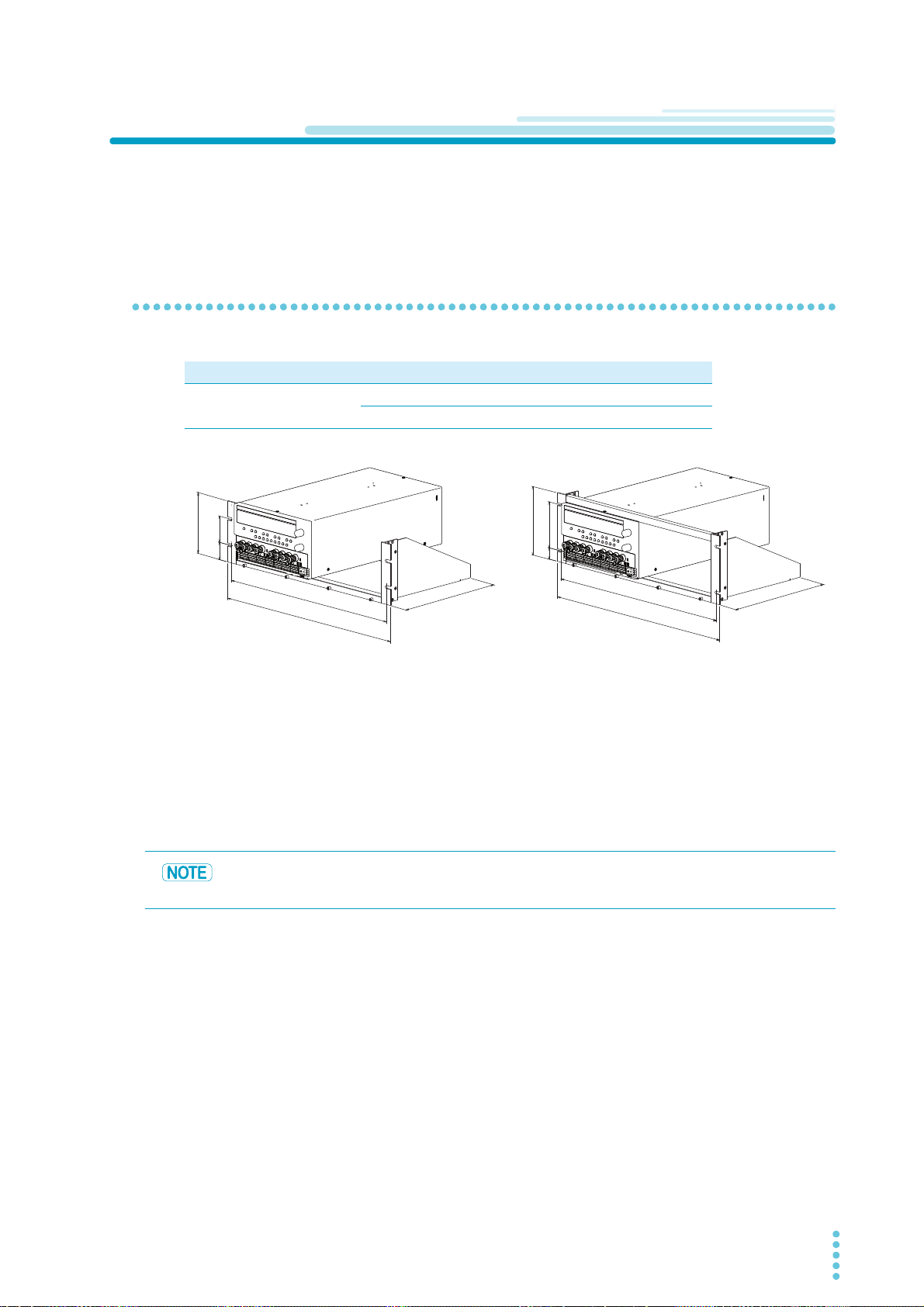
Options
Example of PMX32-2QU
KRA150
( 460 (18.11))
480 (18.90)
( 460 (18.11))
482 (18.98)
149 (5.87)
24.5
(0.96)
100 (3.94)
132.5 (5.22)
57 (2.24)
260 (10.24)
260 (10.24)
37.75
(1.49)
KRA3
Unit: mm (inches)
This product has the following options.
For information about options, contact your Kikusui agent or distributor.
Rack mounting options
Name Model Note
Rack mount adapter KRA3 For EIA inch racks
KRA150 For JIS millimeter racks
Appendix
Remove the handle and feet before you mount the product to a rack.
For information on rack mounting, see the KRA3 or KRA150 operation manual.
Install the suitable support angles applying to the used rack system to support the instrument.
We recommend that you keep all pieces that you remove from the product. You will need these pieces if
you remove the product from the rack mount adapter.
When you re-attach the original feet, use the pieces that you removed.
To reinstall the handle that has been removed, use screw locking agent (e.g., 1401B by
ThreeBond International, Inc.) to prevent screws from loosening.
PMX_MULTI User’s Manual 97
Page 98
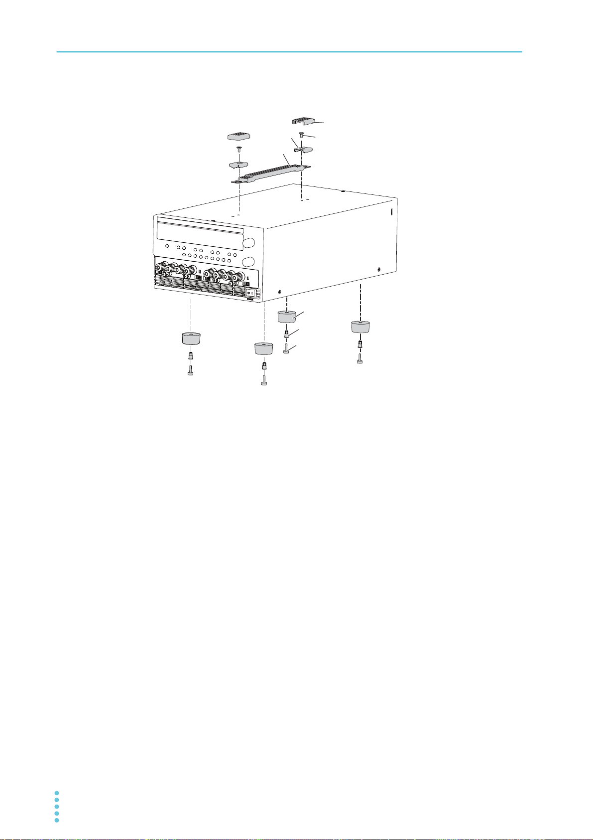
Appendix | Options
Bracket
Handle
Cover
Screw (M48)
Feet
Screw pin
Rivet
Example of PMX32-2QU
Removing the handle and feet
Remove the two handle covers.
1
Unfasten the two screws, and remove the entire handle.
2
While pulling down the rubber feet (four locations), loosen their screw pin with a
3
screwdriver and remove the feet.
This completes the removal.
98 User’s Manual PMX_MULTI
Page 99

Troubleshooting
This section introduces troubleshooting measures. Typical symptoms are listed. Check whether any of the
items listed below apply to your case. In some cases, the problem can be solved quite easily.
If none of the items apply to your case, we recommend that you initialize the product to its factory default
settings (p.96). If following the remedy does not solve your problem, contact your Kikusui agent or distrib-
utor.
Nothing appears on the display when the POWER switch is turned on.
Check Possible cause Remedy See
Is the rated voltage being
applied to the input power
supply (AC)?
Is the product configured
to use a DHCP server for
the LAN interface?
Is the S1 switch on the
rear panel in the correct
position?
The power cord is broken. Check that the power cord is not broken. p.13
The power cord is not connected properly.
A DHCP server environment
is not available or is not in a
good condition.
The switch has not been
returned to the correct position after performing maintenance.
Appendix
Check that the power is connected properly. p.13
Configure the product to not use a DHCP
server (CF41), or consult your network
administrator.
Set the S1 switch on the rear panel to the
correct position.
p.50
p.12
No output is generated even when the output is turned on.
Check Possible cause Remedy See
Is the output voltage set to
0 V and the output current
set to 0 A?
Are you using an external
contact to turn output on
and off?
Is the overvoltage protection (OVP) function activated?
Is the overheat protection
(OHP) function activated?
The output voltage or output current has not been set.
The external control settings
for turning the output on and
off are not correct.
The OVP setting is lower
than the voltage setting.
The internal temperature is
abnormally high.
The air outlet is blocked. Move the product so that there is at least
Set the output voltage and output current to
the required values.
To use external control, use the external
contact to turn the output on. Otherwise, set
the external control parameter for turning
output on and off to off (CF04: OFF).
Set the OVP value higher than the voltage
setting.
Check the operating conditions. After you
have resolved the cause of the abnormal
temperature, turn the output on.
20 cm of space between the vents and the
surrounding walls.Do not place objects
within 20 cm of the vents.
p.28
p.46
p.38
p.41
−
PMX_MULTI User’s Manual 99
Page 100

Appendix | Troubleshooting
The output is unstable
Check Possible cause Remedy See
Is the operation mode
switching from CV to CC
or CC to CV?
Is the remote sensing
function in use?
Are both “CV” and “CC”
displayed?
Are the sensing cable and
load cable conditions normal?
Does the load current have
peaks, or is it pulse
shaped?
Has 30 minutes passed
since the power was
turned on?
The setting (output voltage or
output current) that is limiting
the output is less than the present setting.
The remote sensing function is
turned on.
Remote sensing is causing an
oscillation.
The circuit may be malfunctioning.
The sensing cables or load
cables have poor contact, or
they are broken.
The peak values may be
exceeding the set constant current.
The warm-up time (with the current running) may be insufficient.
Change the setting (output voltage or
output current) that is limiting the output
to a value greater than the present setting. If the setting is at maximum, you
must use a power supply that has a
larger output voltage or current.
When you are not using the remote
sensing function, turn off the SENSE
switch.
Insert a capacitor across the load. p.23
Stop using the product immediately, and
have it repaired.
Turn the POWER switch off, and check
conditions of the cables and the wiring.
Increase the set constant current or
increase the current capacity.
Warm up the product (with the current
running) for at least 30 minutes.
p.34
p.23
−
p.19
p.24
p.34
p.85
The output ripple is large
Check Possible cause Remedy See
Do the ripples become
large occasionally?
Did you change the installation location?
Is external control in use? The external voltage noise is
Was the load connection
changed?
The input voltage is outside the
range.
Something nearby may be generating a strong magnetic or
electrical field.
large.
The remote sensing cables are
not connected.
Apply a voltage that is within the input
voltage range.
Take measures such as moving the
product away from the field sources or
twisting the cables.
Take measures against noise. —
When you are not using remote sensing, disconnect the remote sensing
cables.
p.85
—
p.24
100 User’s Manual PMX_MULTI
 Loading...