

Page 1

Part N0. IA005343
Jul 2019
Communication Interface Manual
PCR-WE Series AC Power Supply
PCR1000WE
PCR2000WE
PCR-WE2 Series AC Power Supply
PCR3000WE2
PCR6000WE2/PCR6000WE2R
PCR12000WE2/PCR12000WE2R
PCR18000WE2/PCR18000WE2R
PCR24000WE2/PCR24000WE2R
PCR30000WE2/PCR30000WE2R
PCR36000WE2/PCR36000WE2R
Page 2

INDEX
Command List .............................
Introduction ...............................
Reading environment.........................
Intended readers................................
Structure of the manual .....................
Trademarks ........................................
Firmware version of the product to which
this manual applies ............................
Measuring instrument interface
standards ...........................................
Copyright ...........................................
Installing the VISA Library .......
Setting Up the Interface ...........
RS232C (standard) ............................
USB (standard) ..................................
LAN (standard) ..................................
Accessing and Operating the Product
from a Web Browser (LAN) ................
GPIB (option) .....................................
About Commands .....................
Command Hierarchy ..........................
Command Syntax ..............................
Parameters ................................
Non-numeric parameters ...................
Numeric parameters ..........................
Special form numeric parameters ......
Phase designation (channel list) ........
Measurement units ............................
25
28
29
51
55
25
25
26
26
26
27
27
30
33
34
40
49
51
52
55
56
57
58
58
7
*OPT ..................................................
*PSC ..................................................
*RCL ..................................................
*RST ..................................................
*SAV ..................................................
*SRE ..................................................
*STB ..................................................
*TRG ..................................................
*TST ...................................................
*WAI ...................................................
ABORt Command .....................
ABOR.................................................
ABOR:ACQ ........................................
ABOR:PROG .....................................
ABOR:SIM .........................................
ABOR:TRAN ......................................
DISPlay Command....................
DISP:CONT .......................................
DISP:PHAS........................................
DISP:MMOD:CURR...........................
DISP:MMOD:VOLT ............................
DISP:MMOD:VOLT:LTL .....................
HCOPy Command .....................
HCOP:SDUM:DATA? .........................
INITiate Command ....................
INIT:ACQ............................................
INIT:PROG .........................................
INIT:SIM .............................................
INIT:TRAN..........................................
64
65
66
67
69
70
71
72
73
74
75
75
76
77
78
79
80
80
81
82
83
84
85
85
86
86
87
88
89
IEEE 488.2 common commands .
59
*CLS ..................................................
*ESE ..................................................
*ESR ..................................................
*IDN ...................................................
*OPC..................................................
KIKUSUI Electronics Corp.
59
60
61
62
63
INSTrument Command .............
INST/ INST:NSEL ..............................
INST:COUP ........................................
LXI Command ...........................
LXI:IDEN ............................................
2
90
90
91
92
92
Page 3

INDEX
MEASure/FETCh Command ....
FETC:<meas-item>/ MEAS:<meas-
item> ..................................................
FETC:ARR:<harm-item>?/
MEAS:ARR:<harm-item>?.................
MEMory Command ...................
MEM:REC ..........................................
MEM:REC:CONF...............................
MEM:REC:PREV ...............................
MEM:SAVE ......................................
OUTPut Command ..................
OUTP ...............................................
OUTP:IMP .......................................
OUTP:IMP:REAC ............................
OUTP:IMP:REAL .............................
OUTP:PHAS:OFF ............................
OUTP:PHAS:OFF:LEV ....................
OUTP:PHAS:ON..............................
OUTP:PHAS:ON:LEV ......................
OUTP:PON ......................................
OUTP:PROT:CLE .............................
OUTP:PROT:WDOG.........................
OUTP:PROT:WDOG:DEL .................
OUTP:SST ........................................
OUTP:SST:FALL ...............................
OUTP:SST:TIME...............................
OUTP:SST:TIME:FALL .....................
PROGram Command ...............
PROG:CLE .......................................
PROG:EDIT ......................................
PROG:EDIT:FUNC:BANK................
PROG:EDIT:JUMP ...........................
PROG:EDIT:IMP ..............................
PROG:EDIT:IMP:REAC ...................
PROG:EDIT:IMP:REAL ....................
PROG:EDIT:PHAS:RAMP ...............
PROG:EDIT:PHAS:STAR ................
PROG:EDIT:PHAS:STOP ................
PROG:EDIT:PHAS:UOFF ................
PROG:EDIT:PHAS:UV.....................
PROG:EDIT:PHAS:UW....................
93
97
100
101
101
102
103
104
105
106
107
108
109
110
111
112
113
114
115
116
117
117
118
120
121
122
123
124
125
126
127
128
129
130
94
96
97
98
99
PROG:EDIT:VOLT ...........................
PROG:EDIT:VOLT:OFFS .................
PROG:EXEC ...................................
PROG:LOOP ...................................
PROG:STAT.....................................
PROG:STEP:END ...........................
PROG:STEP:STAR .........................
SENSe Command ...................
SENS:AVER:COUN .........................
SENS:CURR:HOLD:CLE.................
SENS:CURR:HOLD:TIME ...............
SENS:VOLT:AVER:COUN ...............
SENS:VOLT:HOLD:CLE ..................
SENS:VOLT:HOLD:TIME .................
SIMulation Command .............
SIM:EXEC........................................
SIM:POL ..........................................
SIM:REP:COUN ..............................
SIM:STAT .........................................
SIM:T1:PHAS ..................................
SIM:T1:PHAS:STAT .........................
SIM:T1:TIME....................................
SIM:T2:TIME....................................
SIM:T3:TIME....................................
SIM:T3:VOLT ...................................
SIM:T4:TIME....................................
SIM:T5:CYCL ...................................
SIM:T5:CYCL:STAT .........................
SIM:T5:TIME....................................
131
132
133
134
135
136
137
138
138
139
140
141
142
143
144
144
145
146
147
148
149
150
151
152
153
154
155
156
157
[SOURce:]CURRent Command ...
158
CURR ..............................................
CURR:PEAK ....................................
CURR:PEAK:LOW...........................
CURR:PROT:STAT ..........................
CURR:PROT:TRIP:DEL ...................
158
159
160
161
162
[SOURce:]FREQuency Command
163
FREQ ...............................................
163
3
PCR-WE Interface Manual
Page 4

FREQ:LIM:LOW...............................
FREQ:LIM:UPP ...............................
FREQ:SYNC ....................................
FREQ:SYNC:MODE ........................
FREQ:SYNC:PHAS:DEL .................
FREQ:TRIG .....................................
164
165
166
167
168
169
[SOURce:]FUNCtion Command ..
170
FUNC:BANK ....................................
170
[SOURce:]VOLTage Command ....
171
VOLT ................................................
VOLT:COMP:MODE ........................
VOLT:COMP:RADJ ..........................
VOLT:COMP:SOFT:CONT ...............
VOLT:COMP:SOFT:TERM ...............
VOLT:EXT:INP:EXTDC:ADJ:GAIN ...
VOLT:EXT:INP:EXTDC:ADJ:OFFS ..
VOLT:EXT:INP:EXTDC:APER .........
VOLT:EXT:INP:EXTDC:SIGN:POL ..
VOLT:EXT:INP:EXTDC:SIGN:SOUR
VOLT:EXT:INP:FUNC:MODE ...........
VOLT:EXT:INP:VPR:ADJ:GAIN .......
VOLT:EXT:INP:VPR:ADJ:OFFS .......
VOLT:EXT:INP:VPR:MAP ................
VOLT:EXT:INP:VPR:STAT ...............
VOLT:LIM:LOW ................................
VOLT:LIM:UPP .................................
VOLT:LTL .........................................
VOLT:OFFS .....................................
VOLT:OFFS:LIM:LOW .....................
VOLT:OFFS:LIM:UPP ......................
VOLT:OFFS:LTL ...............................
VOLT:OFFS:TRIG ............................
VOLT:PROT:LOW ............................
VOLT:PROT:PEAK:LOW ..................
VOLT:PROT:PEAK:UPP ..................
VOLT:PROT:LOW:STAT ...................
VOLT:PROT:UPP .............................
VOLT:RANG .....................................
VOLT:RESP .....................................
171
172
173
174
175
176
177
178
179
180
181
182
183
184
185
186
187
188
189
190
191
192
193
194
195
196
197
198
199
200
VOLT:TRIG ......................................
STATus Command ..................
Status Report Structure ...................
Architecture......................................
Status byte register ..........................
Event status register ........................
OPERation status register ...............
STAT:OPER .....................................
STAT:OPER:COND ..........................
STAT:OPER:ENAB ..........................
STAT:OPER:NTR ..............................
STAT:OPER:PTR .............................
OPERation:INSTrument subregister
STAT:OPER:INST ............................
STAT:OPER:INST:COND .................
STAT:OPER:INST:ENAB ..................
STAT:OPER:INST:NTR ....................
STAT:OPER:INST:PTR ....................
OPERation:INSTrument:ISUMma
ry{1|2|3} subregister .........................
STAT:OPER:INST:ISUM{1|2|3} ........
STAT:OPER:INST:ISUM{1|2|3}:COND ...
221
STAT:OPER:INST:ISUM{1|2|3}:ENAB ...
222
STAT:OPER:INST:ISUM{1|2|3}:NTR
STAT:OPER:INST:ISUM{1|2|3}:PTR
QUEStionable status register ..........
STAT:QUES .....................................
STAT:QUES:COND ..........................
STAT:QUES:ENAB ..........................
STAT:QUES:NTR .............................
STAT:QUES:PTR .............................
QUEStionable:INSTrument subregister .
231
STAT:QUES:INST ............................
STAT:QUES:INST:COND .................
STAT:QUES:INST:ENAB ..................
STAT:QUES:INST:NTR ....................
STAT:QUES:INST:PTR ....................
QUEStionable:INSTrument:ISUMmary{1
|2|3} subregister ...............................
201
202
202
204
205
206
207
208
209
210
211
212
213
214
215
216
217
218
219
220
223
224
225
226
227
228
229
230
232
233
234
235
236
237
KIKUSUI Electronics Corp.
4
Page 5

INDEX
STAT:QUES:INST:ISUM{1|2|3} ........
STAT:QUES:INST:ISUM{1|2|3}:COND ...
239
STAT:QUES:INST:ISUM{1|2|3}:ENAB ...
240
STAT:QUES:INST:ISUM{1|2|3}:NTR
STAT:QUES:INST:ISUM{1|2|3}:PTR
Preset status ....................................
STAT:PRES ......................................
SYSTem Command .................
SYST:COMM:RLST .........................
SYST:CONF:ACC ............................
SYST:CONF:ADJ:VOLT:FINE ..........
SYST:CONF:ADJ:VOLT:TERM:MODE ..
247
SYST:CONF:FORM:FRAM ..............
SYST:CONF:FORM:FRAM:INFO ....
SYST:CONF:FORM:PMOD .............
SYST:CONF:FORM:PMOD:INFO....
SYST:CONF:FORM:PSAV:MAX ......
SYST:CONF:FORM:PSAV:MOD .....
SYST:CONF:FORM:PSAV:RES ......
SYST:CONF:PHAS:UOFF ...............
SYST:CONF:PHAS:UV ....................
SYST:CONF:PHAS:UW ...................
SYST:CONF:PON:STAT ..................
SYST:CONF:SSUP ..........................
SYST:CONF:WIR/ SYST:CONF:NOUT .
260
SYST:DATE .....................................
SYST:ERR .......................................
SYST:ERR:COUN............................
SYST:EXT:DIG:READ ......................
SYST:EXT:DIG:WRIT .......................
SYST:EXT:SIGIN:MAP .....................
SYST:EXT:SIGIN:POL .....................
SYST:EXT:SIGIN:STAT ....................
SYST:EXT:SIGOUT:MAP .................
SYST:EXT:SIGOUT:POL ..................
SYST:EXT:SIGOUT:STAT ................
SYST:EXT:SSIGIO:MAP ..................
SYST:EXT:SSIGIO:POL ...................
238
241
242
243
243
244
244
245
246
248
249
250
251
252
253
254
255
256
257
258
259
261
262
263
264
265
266
267
268
269
270
271
272
274
SYST:EXT:SSIGIO:STAT .................
SYST:KLOC .....................................
SYST:LOC/ SYST:REM/ SYST:RWL
SYST:OPT .......................................
SYST:PASS .....................................
SYST:PASS:CDIS ............................
SYST:PASS:NEW ............................
SYST:PASS:STAT ............................
SYST:SEC:IMM ...............................
SYST:SLE ........................................
SYST:SLE:EXEC .............................
SYST:SLE:TIME ..............................
SYST:TIME ......................................
SYST:TIME:ADJ ..............................
SYST:TZON .....................................
SYST:TZON:CAT .............................
SYST:VERS .....................................
TRIGger Command .................
TRIG:ACQ .......................................
TRIG:ACQ:SOUR ............................
TRIG:PROG.....................................
TRIG:PROG:SOUR .........................
TRIG:SIM .........................................
TRIG:SIM:SOUR .............................
TRIG:TRAN .....................................
TRIG:TRAN:SOUR ..........................
WAVE Command .....................
WAVE:DATA:ARB ............................
WAVE:DATA:CLIP............................
WAVE:DATA:IECP ...........................
WAVE:DATA:POIN ...........................
WAVE:DATA:SIN .............................
WAVE:DATA:TYPE ..........................
List of Errors ...........................
Command errors ..............................
Execution errors...............................
Product-specific errors .....................
Query errors.....................................
Operation complete event errors .....
Product-dependent errors ................
275
276
277
278
279
280
281
282
283
284
285
286
287
288
289
290
291
292
292
293
294
295
296
297
298
299
300
300
301
302
303
304
305
306
306
307
308
308
309
309
5
PCR-WE Interface Manual
Page 6

Command processing time ...
312
Tutorial .....................................
Programming AC Output..................
Programming DC Output .................
Trigger Subsystem ...........................
Changing the output with triggers
(TRANsient) .....................................
Measurement (ACQuire)..................
Power line abnormality simulations
(SIMulation) .....................................
Sequence Operation (PROGram)....
Waiting for Operation Complete ......
Status Monitoring .............................
Error Checking .................................
Visual Basic 2017 ............................
313
313
315
316
318
321
326
329
332
333
336
337
KIKUSUI Electronics Corp.
6
Page 7

Command List
Command List
IEEE 488.2 common commands
*CLS
Clears all event registers including the status byte, event status, and error queue.
*ESE
Sets the event status enable register that is counted by the event summary bit (ESB) of the
status byte.
*ESR
Queries the event status register. The event status register is cleared when read.
*IDN
Queries the model name and firmware version of the product.
*OPC
Sets the OPC bit (bit 0) of the event status register when all the commands that are in
standby have been processed.
*OPT
Queries the optional interface boards that are installed in the product.
*PSC
Sets whether the event status enable register and service request enable register are
cleared when the POWER switch is turned on.
*RCL
Recalls memory content.
*RST
Resets a portion of the product settings.
*SAV
Saves the panel settings to memory.
*SRE
Sets the service request enable register.
*STB
Queries the contents of the status byte register and the MSS (master summary status)
message.
7
PCR-WE Interface Manual
Page 8

*TRG
Trigger command.
*TST
Executes a self-test.
*WAI
Prevents the device from executing subsequent commands until all operations that are in
standby have completed.
ABORt Command
ABOR
Aborts configuration, changes, measurements, and other operations in all trigger
subsystems (TRANsient, ACQuire, SIMulation, PROGram).
ABOR:ACQ
Aborts measurement operations.
ABOR:PROG
Stops the trigger function of the sequence operation.
ABOR:SIM
Aborts the trigger function of the power line abnormality simulation.
ABOR:TRAN
Aborts the trigger function for configuration changes.
DISPlay Command
DISP:CONT
Adjusts the screen brightness.
DISP:PHAS
Selects the phase to display on the panel.
DISP:MMOD:CURR
Sets the current, power, or power factor to display on the screen.
DISP:MMOD:VOLT
Sets the voltage (rms value, peak value, average value) to display on the screen.
KIKUSUI Electronics Corp.
8
Page 9

HCOPy Command
DISP:MMOD:VOLT:LTL
Sets the voltage (phase voltage, line voltage) to display on the screen.
HCOPy Command
HCOP:SDUM:DATA?
Retrieves the screen capture of the present screen.
INITiate Command
INIT:ACQ
These commands invalidate the present measured data and start a new measurement.
INIT:PROG
Executes a sequence.
INIT:SIM
Executes a power line abnormality simulation.
INIT:TRAN
Starts the trigger function.
INSTrument Command
INST/ INST:NSEL
Selects the phase that SOURce and MEASure/FETCh commands apply to.
INST:COUP
Sets whether to select all phases.
LXI Command
LXI:IDEN
Turns the identification display on or off.
MEASure/FETCh Command
FETC:<meas-item>/ MEAS:<meas-item>
Queries the scalar measurement data specified with <meas-item>.
9
PCR-WE Interface Manual
Page 10

FETC:ARR:<harm-item>?/ MEAS:ARR:<harm-item>?
Queries the harmonic data specified with <harm-item>.
MEMory Command
MEM:REC
Recalls contents saved in the ABC memory.
MEM:REC:CONF
Sets whether to the memory content is to be confirmed before recalling the ABC memory
from the panel.
MEM:REC:PREV
Displays the contents that are stored in the ABC memory.
MEM:SAVE
Saves the frequency, AC voltage, DC voltage, and waveform bank number to memory.
OUTPut Command
OUTP
Set the output to on or off.
OUTP:IMP
Enables or disables the output impedance.
OUTP:IMP:REAC
Sets the reactance component of the output impedances.
OUTP:IMP:REAL
Sets the resistance component of the output impedances.
OUTP:PHAS:OFF
Enables or disables output-off phase control.
OUTP:PHAS:OFF:LEV
Sets the output off phase angle.
OUTP:PHAS:ON
Enables or disables output-on phase control.
OUTP:PHAS:ON:LEV
Sets the output-on phase angle.
KIKUSUI Electronics Corp.
10
Page 11

PROGram Command
OUTP:PON
Sets the output state that the PCR-WE will be in when the power is turned on.
OUTP:PROT:CLE
Clears alarms.
OUTP:PROT:WDOG
Enables or disables the communication monitoring (WATCHDOG) timer.
OUTP:PROT:WDOG:DEL
Sets the delay time of the communication monitoring (WATCHDOG) timer.
OUTP:SST
Enables or disables soft start.
OUTP:SST:FALL
Enables or disables soft stop.
OUTP:SST:TIME
Sets the soft start rise time.
OUTP:SST:TIME:FALL
Sets the soft stop fall time.
PROGram Command
PROG:CLE
Sets all the steps in the sequence to their default values.
デフォルトになるまでには、約 3 秒か かります 。
PROG:EDIT
Collectively sets a sequence step (frequency, voltage, signal change, step time, waveform
bank, status output, trigger I/O, output).
PROG:EDIT:FUNC:BANK
Sets the waveform bank number of the sequence step.
PROG:EDIT:JUMP
Configures the jump settings of a sequence step.
PROG:EDIT:IMP
Sets whether to set the output impedance in the sequence step.
11
PCR-WE Interface Manual
Page 12

PROG:EDIT:IMP:REAC
Sets the reactance component of the output impedance used in the sequence step.
PROG:EDIT:IMP:REAL
Sets the resistance component of the output impedance used in the sequence step.
PROG:EDIT:PHAS:RAMP
Sets the phase signal change of a sequence step.
PROG:EDIT:PHAS:STAR
Sets the starting phase angle and whether to suddenly change the phase of the sequence
step.
PROG:EDIT:PHAS:STOP
Sets the ending phase angle of the sequence step.
PROG:EDIT:PHAS:UOFF
Sets the U phase offset phase angle of a sequence step.
PROG:EDIT:PHAS:UV
Sets the U-V phase difference of the sequence step.
PROG:EDIT:PHAS:UW
Sets the U-W phase difference of the sequence step.
PROG:EDIT:VOLT
Sets the unbalanced AC voltage of the sequence step
PROG:EDIT:VOLT:OFFS
Sets the unbalanced DC voltage of the sequence step
PROG:EXEC
Queries the sequence execution state.
PROG:LOOP
Sets the sequence repetition count.
PROG:STAT
Changes the execution state of the sequence.
PROG:STEP:END
Sets the sequence ending step number
PROG:STEP:STAR
Sets the sequence starting step number
KIKUSUI Electronics Corp.
12
Page 13

SENSe Command
SENS:AVER:COUN
Sets the moving average count for current measurement.
SENS:CURR:HOLD:CLE
Clears the hold time of the peak current..
SENS:CURR:HOLD:TIME
Sets the hold time of the peak current.
SENS:VOLT:AVER:COUN
Sets the moving average count for voltage measurement.
SENS:VOLT:HOLD:CLE
Clears the hold time of the peak voltage.
SENS:VOLT:HOLD:TIME
Sets the hold time of the peak voltage.
SIMulation Command
SIM:EXEC
Queries the execution status of power line abnormality simulations.
SENSe Command
SIM:POL
Sets the voltage regulation polarity of power line abnormality simulations.
SIM:REP:COUN
Sets the number of repetitions of power line abnormality simulations.
SIM:STAT
Executes or stops a power line abnormality simulation.
SIM:T1:PHAS
Sets the voltage regulation starting phase of power line abnormality simulations.
SIM:T1:PHAS:STAT
Selects whether the voltage regulation start of power line abnormality simulations will be
set in terms of time or in terms of phase.
SIM:T1:TIME
Sets the voltage regulation starting time of power line abnormality simulations.
13
PCR-WE Interface Manual
Page 14

SIM:T2:TIME
Sets slope time 1 of power line abnormality simulations.
SIM:T3:TIME
Sets the voltage regulation time of power line abnormality simulations.
SIM:T3:VOLT
Sets the regulated voltage of power line abnormality simulations.
SIM:T4:TIME
Sets slope time 2 of power line abnormality simulations.
SIM:T5:CYCL
Sets the number of return cycles of power line abnormality simulations.
SIM:T5:CYCL:STAT
Selects whether the period that the PCR-WE remains in the returned state is configured in
terms of time or in terms of cycles for power line abnormality simulations.
SIM:T5:TIME
Sets the return time of power line abnormality simulations.
[SOURce:]CURRent Command
CURR
Sets the upper limit of the output current.
CURR:PEAK
Sets the output current peak limit of the positive electric potential
CURR:PEAK:LOW
Sets the output current peak limit of the negative electric potential
CURR:PROT:STAT
Sets how the PCR-WE acts when the current limit is exceeded.
CURR:PROT:TRIP:DEL
Sets the time that must elapse before the output is turned off when the current limit is
exceeded
KIKUSUI Electronics Corp.
14
Page 15

[SOURce:]FREQuency Command
[SOURce:]FREQuency Command
FREQ
Sets the frequency.
FREQ:LIM:LOW
Sets the lower frequency limit.
FREQ:LIM:UPP
Sets the upper frequency limit.
FREQ:SYNC
Sets the sync function.
FREQ:SYNC:MODE
Sets the input sync signal of the sync function.
FREQ:SYNC:PHAS:DEL
Sets the synchronization delay phase angle of the synchronization function.
FREQ:TRIG
Sets the frequency to change to when INIT/INIT:TRAN or a software trigger is sent.
[SOURce:]FUNCtion Command
FUNC:BANK
Specifies the number of the waveform bank that you want to execute.
[SOURce:]VOLTage Command
VOLT
Set the AC voltage.
VOLT:COMP:MODE
Sets the compensation (voltage compensation).
VOLT:COMP:RADJ
Sets the voltage to correct with regulation adjustment.
VOLT:COMP:SOFT:CONT
Set the soft sensing control target.
15
PCR-WE Interface Manual
Page 16

VOLT:COMP:SOFT:TERM
Set the sensing point.
VOLT:EXT:INP:EXTDC:ADJ:GAIN
Sets the gain for when the input waveform is amplified using an external analog signal.
VOLT:EXT:INP:EXTDC:ADJ:OFFS
Sets the offset for when the input waveform is amplified using an external analog signal.
VOLT:EXT:INP:EXTDC:APER
Sets the measurement time for when the input waveform is amplified using an external
analog signal.
VOLT:EXT:INP:EXTDC:SIGN:POL
Sets the signal polarity of each channel for when the input waveform is amplified using an
external analog signal.
VOLT:EXT:INP:EXTDC:SIGN:SOUR
Sets the signal source for when the input waveform is amplified using an external analog
signal.
VOLT:EXT:INP:FUNC:MODE
Selects the parameter to control with the external analog signal.
VOLT:EXT:INP:VPR:ADJ:GAIN
Sets the gain for when varying the voltage or frequency with the external analog signal.
VOLT:EXT:INP:VPR:ADJ:OFFS
Sets the offset for when varying the voltage or frequency with the external analog signal.
VOLT:EXT:INP:VPR:MAP
Sets the channel configuration for when varying the voltage or frequency with the external
analog signal.
VOLT:EXT:INP:VPR:STAT
Turns on or off the output of each channel for when varying the voltage or frequency with
the external analog signal.
VOLT:LIM:LOW
Sets the lower AC voltage limit.
VOLT:LIM:UPP
Sets the upper AC voltage limit.
KIKUSUI Electronics Corp.
16
Page 17

[SOURce:]VOLTage Command
VOLT:LTL
Sets the line AC voltage.
VOLT:OFFS
Sets the DC voltage.
VOLT:OFFS:LIM:LOW
Sets the lower DC voltage limit.
VOLT:OFFS:LIM:UPP
Sets the upper DC voltage limit.
VOLT:OFFS:LTL
Sets the line DC voltage.
VOLT:OFFS:TRIG
Sets the DC voltage to change to when INIT:TRAN or a software trigger is sent.
VOLT:PROT:LOW
Sets the UVP value.
VOLT:PROT:PEAK:LOW
Sets the negative peak OVP value.
VOLT:PROT:PEAK:UPP
Sets the positive peak OVP value.
VOLT:PROT:LOW:STAT
Enables/disables UVP.
VOLT:PROT:UPP
Sets the OVP (rms) value.
VOLT:RANG
Sets the voltage range.
VOLT:RESP
Sets the response speed.
VOLT:TRIG
Sets the AC voltage to change to when INIT:TRAN or a software trigger is sent.
17
PCR-WE Interface Manual
Page 18

STATus Command
STAT:OPER
Queries the event of the OPERation status register.
STAT:OPER:COND
Queries the condition of the OPERation status register.
STAT:OPER:ENAB
Sets the enable register of the OPERation status register.
STAT:OPER:NTR
Sets the negative transition filter of the OPERation status register.
STAT:OPER:PTR
Sets the positive transition filter of the OPERation status register.
STAT:OPER:INST
Queries the event of the OPERation:INSTrument subregister.
STAT:OPER:INST:COND
Queries the condition of the OPERation:INSTrument subregister.
STAT:OPER:INST:ENAB
Sets the enable register of the OPERation:INSTrument subregister.
STAT:OPER:INST:NTR
Sets the negative transition filter of the OPERation:INSTrument subregister.
STAT:OPER:INST:PTR
Sets the positive transition filter of the OPERation:INSTrument subregister.
STAT:OPER:INST:ISUM{1|2|3}
Queries the event of the OPERation:INSTrument:ISUMmary{1|2|3} subregister.
STAT:OPER:INST:ISUM{1|2|3}:COND
Queries the condition of the OPERation:INSTrument:ISUMmary{1|2|3} subregister.
STAT:OPER:INST:ISUM{1|2|3}:ENAB
Sets the enable register of the OPERation:INSTrument:ISUMmary{1|2|3} subregister.
STAT:OPER:INST:ISUM{1|2|3}:NTR
Sets the negative transition filter of the OPERation:INSTrument:ISUMmary{1|2|3}
subregister.
KIKUSUI Electronics Corp.
18
Page 19

STATus Command
STAT:OPER:INST:ISUM{1|2|3}:PTR
Sets the positive transition filter of the OPERation:INSTrument:ISUMmary{1|2|3}
subregister.
STAT:QUES
Queries the event of the QUEStionable status register.
STAT:QUES:COND
Queries the condition of the QUEStionable status register.
STAT:QUES:ENAB
Sets the enable register of the QUEStionable status register.
STAT:QUES:NTR
Sets the negative transition filter of the QUEStionable status register.
STAT:QUES:PTR
Sets the positive transition filter of the QUEStionable status register.
STAT:QUES:INST
Queries the event of the QUEStionable:INSTrument subregister.
STAT:QUES:INST:COND
Queries the condition of the QUEStionable:INSTrument subregister.
STAT:QUES:INST:ENAB
Sets the enable register of the QUEStionable:INSTrument subregister.
STAT:QUES:INST:NTR
Sets the negative transition filter of the QUEStionable:INSTrument subregister.
STAT:QUES:INST:PTR
Sets the positive transition filter of the QUEStionable:INSTrument subregister.
STAT:QUES:INST:ISUM{1|2|3}
Queries the event of the QUEStionable:INSTrument:ISUMmary{1|2|3} subregister.
STAT:QUES:INST:ISUM{1|2|3}:COND
Queries the condition of the QUEStionable:INSTrument:ISUMmary{1|2|3} subregister.
STAT:QUES:INST:ISUM{1|2|3}:ENAB
Sets the enable register of the QUEStionable:INSTrument:ISUMmary{1|2|3} subregister.
19
PCR-WE Interface Manual
Page 20

STAT:QUES:INST:ISUM{1|2|3}:NTR
Sets the negative transition filter of the QUEStionable:INSTrument:ISUMmary{1|2|3}
subregister.
STAT:QUES:INST:ISUM{1|2|3}:PTR
Sets the positive transition filter of the QUEStionable:INSTrument:ISUMmary{1|2|3}
subregister.
STAT:PRES
Resets the ENABle, PTRansition, and NTRansition filter registers of all status registers
(including sub registers) to their default values.
SYSTem Command
SYST:COMM:RLST
Sets the product to remote or local mode.
SYST:CONF:ACC
Enables/disables AC coupling.
SYST:CONF:ADJ:VOLT:FINE
Sets the output voltage offset.
SYST:CONF:ADJ:VOLT:TERM:MODE
Set whether the sensing function is enabled or disabled for the voltage offset setting.
SYST:CONF:FORM:FRAM
Queries the number of units operating in parallel.
SYST:CONF:FORM:FRAM:INFO
Queries the information about the specified PCR-WE.
SYST:CONF:FORM:PMOD
Queries the number of power modules in the specified PCR-WE.
SYST:CONF:FORM:PMOD:INFO
Queries the information about the specified power module.
SYST:CONF:FORM:PSAV:MAX
Sets the maximum expected power of the power-saving function.
SYST:CONF:FORM:PSAV:MOD
Sets all power modules to run using the power-saving function.
KIKUSUI Electronics Corp.
20
Page 21

SYST:CONF:FORM:PSAV:RES
Resets the maximum expected power setting of the power-saving function.
SYST:CONF:PHAS:UOFF
Sets the absolute phase angle of the U phase relative to the reference phase.
SYST:CONF:PHAS:UV
Sets the U-V phase difference.
SYST:CONF:PHAS:UW
Sets the U-W phase difference.
SYST:CONF:PON:STAT
Sets the condition panel setting state when the POWER switch is turned on.
SYST:CONF:SSUP
Enables or disables the voltage surge suppression function.
SYST:CONF:WIR/ SYST:CONF:NOUT
Sets the output method.
SYST:DATE
Sets the date (UTC).
SYSTem Command
SYST:ERR
Reads the oldest error information or event information from the error queue.
SYST:ERR:COUN
Queries the number of errors occurring currently.
SYST:EXT:DIG:READ
Queries all the signal input states of SIGNAL IN channels (CTRL.1 to CTRL.4) and SIGNAL
IO channels (DIO.1, DIO.2).
SYST:EXT:DIG:WRIT
Outputs the SIGNAL OUT channels (STAT.1 to STAT.4) and SIGNAL IO channels (DIO.1,
DIO.2) collectively.
SYST:EXT:SIGIN:MAP
Maps SIGNAL IN channels (CTRL.1 to CTRL.3).
SYST:EXT:SIGIN:POL
Sets the polarity of the parameter to map to SIGNAL IN.
21
PCR-WE Interface Manual
Page 22

SYST:EXT:SIGIN:STAT
Queries the signal level of the SIGNAL IN channel.
SYST:EXT:SIGOUT:MAP
Maps SIGNAL OUT channels (STAT.1 to STAT.3).
SYST:EXT:SIGOUT:POL
Sets the polarity of the parameter to map to SIGNAL OUT.
SYST:EXT:SIGOUT:STAT
Sets the signal level of the SIGNAL OUT channel.
SYST:EXT:SSIGIO:MAP
Maps SIGNAL IO channels (DIO.1, DIO.2).
SYST:EXT:SSIGIO:POL
Sets the polarity of the parameter to map to SIGNAL IO.
SYST:EXT:SSIGIO:STAT
Sets the signal level of the SIGNAL IO channel.
SYST:KLOC
Sets or releases panel control lock.
SYST:LOC/ SYST:REM/ SYST:RWL
This is an old style command.
SYST:OPT
Queries the optional interface boards that are installed in the product.
SYST:PASS
Enables a password-protected command.
SYST:PASS:CDIS
Disable the password-protected command.
SYST:PASS:NEW
Set the password.
SYST:PASS:STAT
Queries whether a password-protected command is valid or invalid.
SYST:SEC:IMM
Sanitizes the product to its factory default settings.
KIKUSUI Electronics Corp.
22
Page 23

TRIGger Command
SYST:SLE
Turns the sleep function on and off.
SYST:SLE:EXEC
Activates sleep mode immediately.
SYST:SLE:TIME
Sets the time that must elapse before the product enters sleep mode.
SYST:TIME
Sets the time.
SYST:TIME:ADJ
Automatically synchronizes the system clock using the NTP server on the network.
SYST:TZON
Sets the time zone of the system clock.
SYST:TZON:CAT
Queries the time zone IDs that can be used.
SYST:VERS
Queries the version of the SCPI specifications that the product complies with.
TRIGger Command
TRIG:ACQ
Executes a software trigger on the ACQuire trigger subsystem.
TRIG:ACQ:SOUR
Sets the condition (trigger source) for actually starting the measurement after the ACQuire
trigger subsystem receives an INIT:ACQ.
TRIG:PROG
Executes a software trigger on the PROGram trigger subsystem.
TRIG:PROG:SOUR
Sets the condition (trigger source) for actually starting the sequence operation after the
PROGram trigger subsystem receives an INIT:PROG.
TRIG:SIM
Executes a software trigger on the SIMulation trigger subsystem.
23
PCR-WE Interface Manual
Page 24

TRIG:SIM:SOUR
Sets the condition (trigger source) for actually executing the simulation after the SIMulation
trigger subsystem receives an INIT:SIM.
TRIG:TRAN
Executes a software trigger on the TRANsient trigger subsystem.
TRIG:TRAN:SOUR
Sets the condition (trigger source) for actually changing the settings after the TRANsient
trigger subsystem receives an INIT:TRAN.
WAVE Command
WAVE:DATA:ARB
Sets a user-defined waveform with block data at the waveform bank that you specify by its
number.
WAVE:DATA:CLIP
Sets the crest factor of the peak clipped waveform at the waveform bank that you specify
by its number.
WAVE:DATA:IECP
Sets the clip factor of the flat curve waveform at the waveform bank that you specify by its
number.
WAVE:DATA:POIN
Sets a user-defined waveform by specifying the waveform bank number and the point.
WAVE:DATA:SIN
Sets the waveform bank that you specify by its number to sine wave.
WAVE:DATA:TYPE
Queries the waveform type at the waveform bank that you specify by its number.
KIKUSUI Electronics Corp.
24
Page 25

Introduction
Introduction
The PCR-WE Series Communication Interface Manual explains the settings that are
used to control the PCR-WE series remotely through the following interfaces and the
available commands.
• RS232C interface (standard)
• USB interface (standard)
• LAN interface (standard)
• GPIB interface (option)
When the product is operating under remote control, REMOTE appears on the front
panel display. To switch the product back to local mode from the front panel, press
LOCAL.
Reading environment
We recommend the following environment for viewing this manual.
PDF Reader: Adobe Reader
Intended readers
This manual is written for readers with sufficient basic knowledge of how to control
measuring instruments using a PC.
Familiarize yourself with the syntax of the SCPI commands that are used with the
product before you use them.
25
PCR-WE Interface Manual
Page 26

Structure of the manual
This manual consists of the following sections.
• Overview
• Setup
• Message Overview
• Command
• Appendix
• Tutorial
Trademarks
Microsoft Windows is a trademark of Microsoft Corporation in the United States and/
or other countries.
All other company and product names used in this guide are trademarks or registered
trademarks of their respective owners.
Firmware version of the product to which this manual applies
This manual applies to products with firmware versions 1.3x.
KIKUSUI Electronics Corp.
26
Page 27

Introduction
Measuring instrument interface standards
This product complies with the following standards.
• IEEE Std 488.2-1992 IEEE Standard Codes, Formats, Protocols, and Common
Commands For Use With IEEE Std 488.1-1987
• IEEE Std 488.1-1987 IEEE Standard Digital Interface for Programmable Instrumen-
tation
• Standard Commands for Programmable Instruments (SCPI) version 1999.0
• Universal Serial Bus Specification Rev 2.0
• Universal Serial Bus Test and Measurement Class Specification (USBTMC) Rev 1.0
• Universal Serial Bus Test and Measurement Class, Subclass USB488 Specification
(USBTMC-USB488) Rev 1.0
• TCP/IP Instrument Protcol Specification VXI-11 Rev 1.0 1995
• TCP/IP-IEEE488.2 Interface Specification VXI-11.3 Draff 0.3 1995
• LXI Device Specification 2016 Rev 1.5
• LXI HiSLIP Extended Function Rev 1.02
• LXI Extended Function IPv6 Rev 1.1
• IVI-6.1 IVI High-Speed LAN Instrument Protocol (HiSLIP) Rev 1.1
• VPP-4.3 The VISA Library 2015 Rev 5.5
Copyright
The contents of this manual may not be reproduced, in whole or in part, without the
prior consent of the copyright holder.
The specifications of this product and the contents of this manual are subject to
change without prior notice.
Copyright©2018
27
PCR-WE Interface Manual
Page 28
Installing the VISA Library
VISA (Virtual Instrument Software Architecture) was developed by the IVI Foundation.
It is the standard specification for measurement instrument connection software.
To use the VISA library (VISA COM) with the I/O library, the VISA library must be in-
stalled on the controller (Windows).
To use the LAN interface to control the product, middleware that supports the SC-
PI-Telnet, VXI-11, HiSLIP, or SCPI-RAW protocol is required. The middleware is in-
stalled automatically by the VISA library.
You have to install one of the following VISA libraries (driver software that is imple-
mented according to the VISA specifications).
• NI-VISA by National Instruments Corporation (Ver. 5.1.1 or later)
• Keysight VISA (Keysight IO Libraries Suite 16.0 or later) by Keysight Technologies
• KI-VISA Ver. 5.0.4 or later
Note
Depending on the interface, you may not be able to use your VISA library if it is an
older version than that specified.
KIKUSUI Electronics Corp.
28
Page 29

Setting Up the Interface
Setting Up the Interface
The product is standard equipped with RS232C, USB, and LAN interfaces.
There is no need to switch interfaces. All interfaces can be used simultaneously. Each
interface can be turned off using CONFIG settings.
RS232C (standard)
USB (standard)
LAN (standard)
Accessing and Operating the Product from a Web Browser (LAN)
GPIB (option)
29
PCR-WE Interface Manual
Page 30
RS232C (standard)
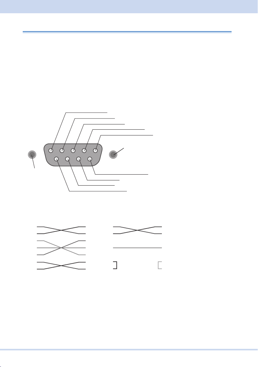
Crossover cable example 1
D-sub9pin
Crossover cable example 2
1: CD (carrier detect)
■ RS232C connection
Turn off the product and the PC.
For the RS232C cable, use a D-sub, 9-pin, female-to-female AT crossover cable. The
port pinout is shown below.
If you are not using flow control, you do not have to connect all the pins. (See the
second crossover cable wiring example below.)
2: RXD (receive data)
3: TXD (transmit data)
4: DTR (data terminal ready)
5: GND (signal ground)
#4-40UNC
inch screw
#4-40UNC
inch screw
Viewing the front panel
1
2
3
4
5
6
7
8
9
D-sub9pin
female
6: DSR (data set ready)
D-sub9pin
female
9: RI (ring indicator)
8: CTS (clear to send)
7: RTS (request to send)
1
2
3
4
5
6
7
8
9
1
2
3
4
5
6
7
8
9
D-sub9pin
female
1
2
3
4
5
6
7
8
9
female
9-pin AT connector (Flow control cannot be performed using the cable described in
the second crossover cable wiring example.)
KIKUSUI Electronics Corp.
30
Page 31
Setting Up the Interface
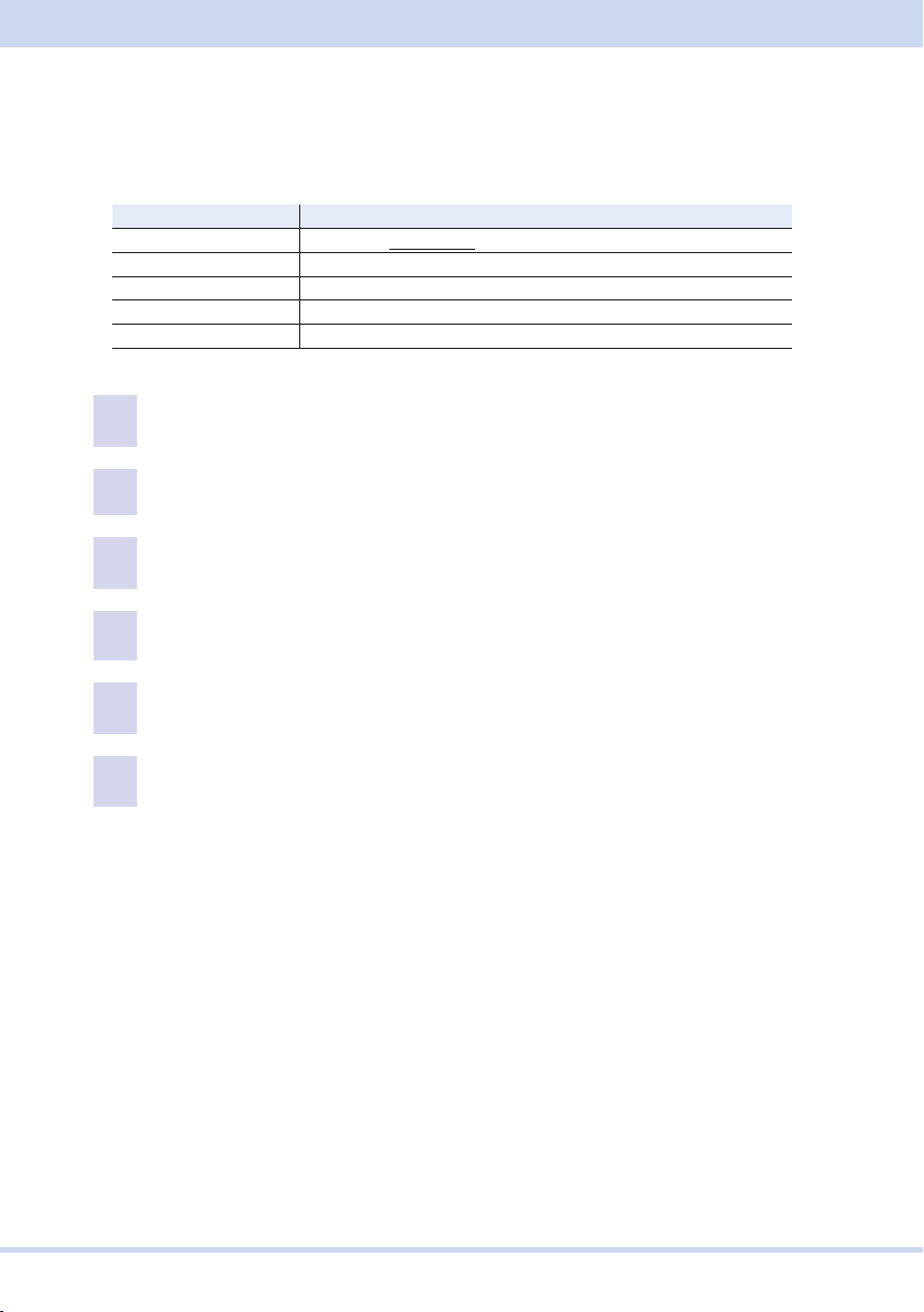
■ RS232C settings
The RS232C protocol is shown in the following table.
The factory default RS232C settings are RS232C enabled and 19200 bps data rate.
Parameter Value
Baudrate: 9 600 bps, 19 200 bps, 38 400 bps, 57 600 bps, 115 200 bps
Data length: 8 bits
Stop bits: 1 bit
Parity: None
Flow Ctrl: NONE, Xon/Xoff
Press CONFIG (SHIFT+OPR MODE) > COM-I/F (F1) > RS232C (F3).
1
The present RS232C settings are displayed.
To enable RS232C, press ENABLE (F1). To disable it, press DISABLE (F2).
2
Press BITRATE (F3) to set the data rate.
3
For the settings, see the table under Protocol below.
Press FLOW CTRL (F4) to set flow control.
4
To disable flow control, press NONE (F1). To enable it, press XON/XOFF (F2).
Press ESC > APPLY (F5).
5
To cancel, press CANCEL (F6).
Turn the PCR-WEʼs POWER switch off and then back on.
6
The settings take effect.
31
PCR-WE Interface Manual
Page 32
■ X-Flow control
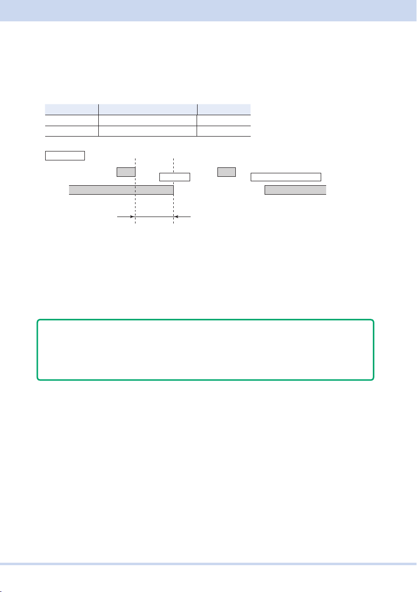
within 10 characters after receiving DC3.
The transmission/reception on the PCR-WE/WE2 can be controlled using Xon/Xoff.
DC (device control) codes are used as control codes.
Data may not be received properly if flow control is not used.
Code Function ASCII Code
DC1 (Xon) Transmission request 11H
DC3 (Xoff) Transmission stop request 13H
PCR-WE
TXD
RXD
DC3
The RS232C terminal must pause transmission
Within 10
characters
Pause
DC1
Resume transmission
■ Break signal
The break signal is used as a substitute for the IEEE488.1 dcl/sdc (Device Clear, Se-
lected Device Clear) message.
Note
To use the RS232C interface, a “SYSTem:COMM:RLST REM” command must be
sent to set the product to remote mode. To use remote programming, send “SYS-
T:COMM:RLST REM” at the beginning of the program.
KIKUSUI Electronics Corp.
32
Page 33

Setting Up the Interface
USB (standard)
To use the USB interface to control the product, a device driver that supports the USB
Test & Measurement class (USBTMC) must be installed on the controller. The USBT-
MC driver is installed automatically by the VISA library.
■ USB connection
Connect the product to a PC using a USB cable.
■ USB settings
The factory default USB setting is “USB enabled.”
Press CONFIG (SHIFT+OPR MODE) > COM-I/F (F1) > USB (F2).
1
To enable USB, press ENABLE (F1). To disable it, press DISABLE (F2).
2
Press APPLY (F5).
3
To cancel, press CANCEL (F6).
Turn the PCR-WEʼs POWER switch off and then back on.
4
The settings take effect.
■ Service request
The product is equipped with service request and serial polling functions.
■ USB function
Complies with USB Specification 2.0
Complies with USBTMC Specification 1.0 and USBTMC-USB488 Specification 1.0
Baud rate: 480 Mbps maximum (high speed)
VID (vendor ID)
0x0B3E
PID (product ID)
PCR-WE: 0x104D
PCR-WE2: 0x104E
PCR-WE2R: 0x1054
33
PCR-WE Interface Manual
Page 34
LAN (standard)
WARNING
If a network problem occurs, an unexpected dangerous voltage may oc-
cur that may cause electric shock, fire, physical damage to the DUT, and
so on. If you are going to remotely control the PCR-WE from a distance,
install a Web camera or take other measures to monitor the status.
To use the LAN interface to control the product, middleware that supports the SC-
PI-Telnet, VXI-11, HiSLIP, or SCPI-RAW protocol is required. The middleware is in-
stalled automatically by the VISA library.
The LAN interface board has a Web browser interface (Web Browser Interface). You
can configure the LAN interface settings from your PCʼs Web browser.
For information on topics such as connecting to your corporate LAN, your IP address,
your host name, and security, contact your network administrator.
If you are using a host name (a Bonjour host name), you have to install Apple Bon-
jour.
■ LAN connection
Use a standard LAN cable (category 5 and straight) to connect the product to a net-
work hub or router.
KIKUSUI Electronics Corp.
34
Page 35
Setting Up the Interface
■ LAN settings
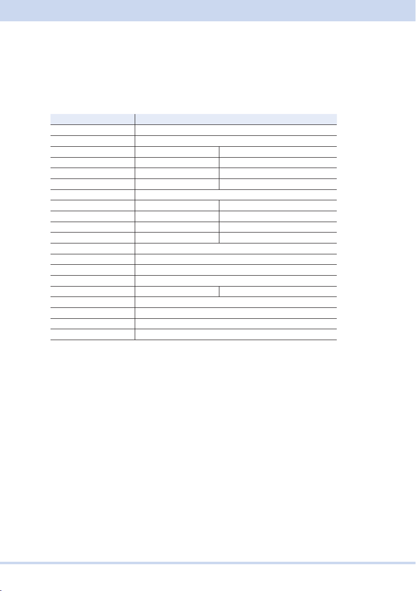
Checking the settings
For IPv4, press CONFIG (SHIFT+OPR MODE) > COM-I/F (F1) > LAN (F1). For IPv6,
press CONFIG (SHIFT+OPR MODE) > COM-I/F (F1) > LAN (F1) > IPv6 (F6).
Parameter IPv4 value IPv6 value
Status Present LAN status
IP Address Source IP address assignment
Grobal Address Global address
IP Address IP address
LinkLocal Address IP address
Subnet Mask Subnet mask
Default Gateway Default gateway
DNS Servers DNS server address
WINS Servers WINS server address
Primary DNS Primary DNS server address
Secondary DNS Secondary DNS server address
mDNS Hostname mDNS host name
mDNS Serice Name mDNS service name
DDNS Hostname DDNS host name
Domain domain
NetBIOS Name NetBIOS name
SCPI-RAW Port SCPI TCP/IP socket port
SCPI-Telnet Port SCPI Telnet port
HiSLIP Port HiSLIP port
MAC Address MAC address
35
PCR-WE Interface Manual
Page 36
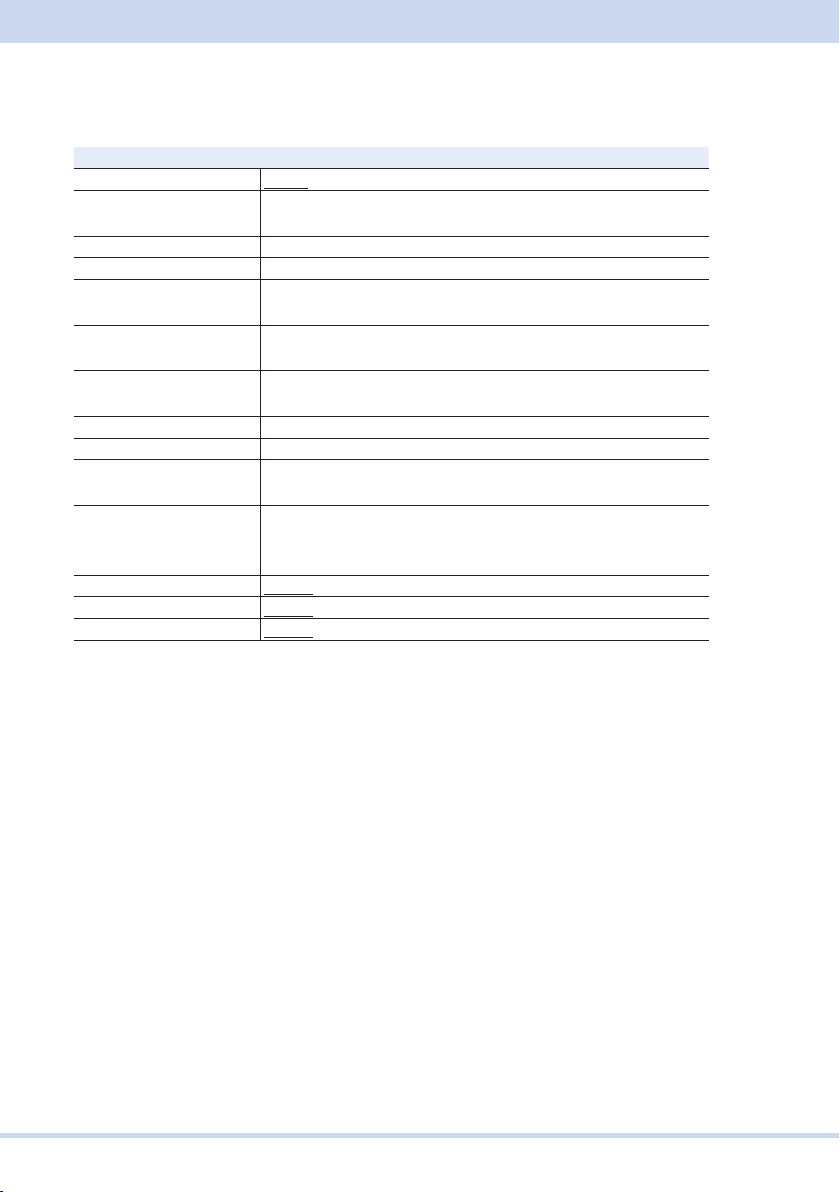
Change the parameter value.
Normally, set “IP Address Assign” to “AUTO” (factory default setting).
Parameter Value
IP Address Assign AUTO (auto), STATIC (fixed), DISABLE (disable IPv4/IPv6)
IP Address
Subnet Mask
Subnet Prefix Length
Default Gateway
Primary DNS
Secondary DNS
Primary WINS
Secondary WINS
*2
*2*3
*2*4
*2
*2
*2
*2*3
*2*3
Hostname Enter the host name (up to 15 characters). Factory default is
Description Enter the service name (up to 63 characters). The factory de-
mDNS Enable/Disable
Dynamic DNS Enable/Disable
NetBbIOS Over TCP/IP*3Enable/Disable
*1
. Factory default settings are underlined.
*2
. Can be set when the IP address assignment method is Static.
*3
. IPv4 only.
*4
. IPv6 only.
*1
0.0.0.0 to 254.254.254.254 (IPv4)
0 to 9 and a to f allowed (IPv6)
0.0.0.0 to 255.255.255.255
16 to 112
0.0.0.0 to 254.254.254.254 (IPv4)
0 to 9 and a to f allowed (IPv6)
0.0.0.0 to 254.254.254.254 (IPv4)
0 to 9 and a to f allowed (IPv6)
0.0.0.0 to 254.254.254.254 (IPv4)
0 to 9 and a to f allowed (IPv6)
0.0.0.0 to 254.254.254.254
0.0.0.0 to 254.254.254.254
model name and serial number.
fault setting is KIKUSUI XXXX AC Power Supply (where XXXX
is the model name) and serial number
KIKUSUI Electronics Corp.
36
Page 37
Setting Up the Interface
For IPv4, press CONFIG (SHIFT+OPR MODE) > COM-I/F (F1) > LAN (F1).
1
For IPv6, press CONFIG (SHIFT+OPR MODE) > COM-I/F (F1) > LAN (F1) >
IPv6 (F6).
The present settings are displayed.
Press MODIFY (F3).
2
Select the parameter you want to change, press EDIT (F3), and change
3
the value.
For parameters other than the IP address assignment method, multicast DNS, dynamic DNS, and NetBIOS Over TCP/IP, press OK (F4) after you set the value. You
can cancel a setting by pressing CANCEL (F6).
When you are finished with the settings, press APPLY (F5).
4
To cancel, press CANCEL (F6).
Turn the PCR-WEʼs POWER switch off and then back on.
5
The settings take effect.
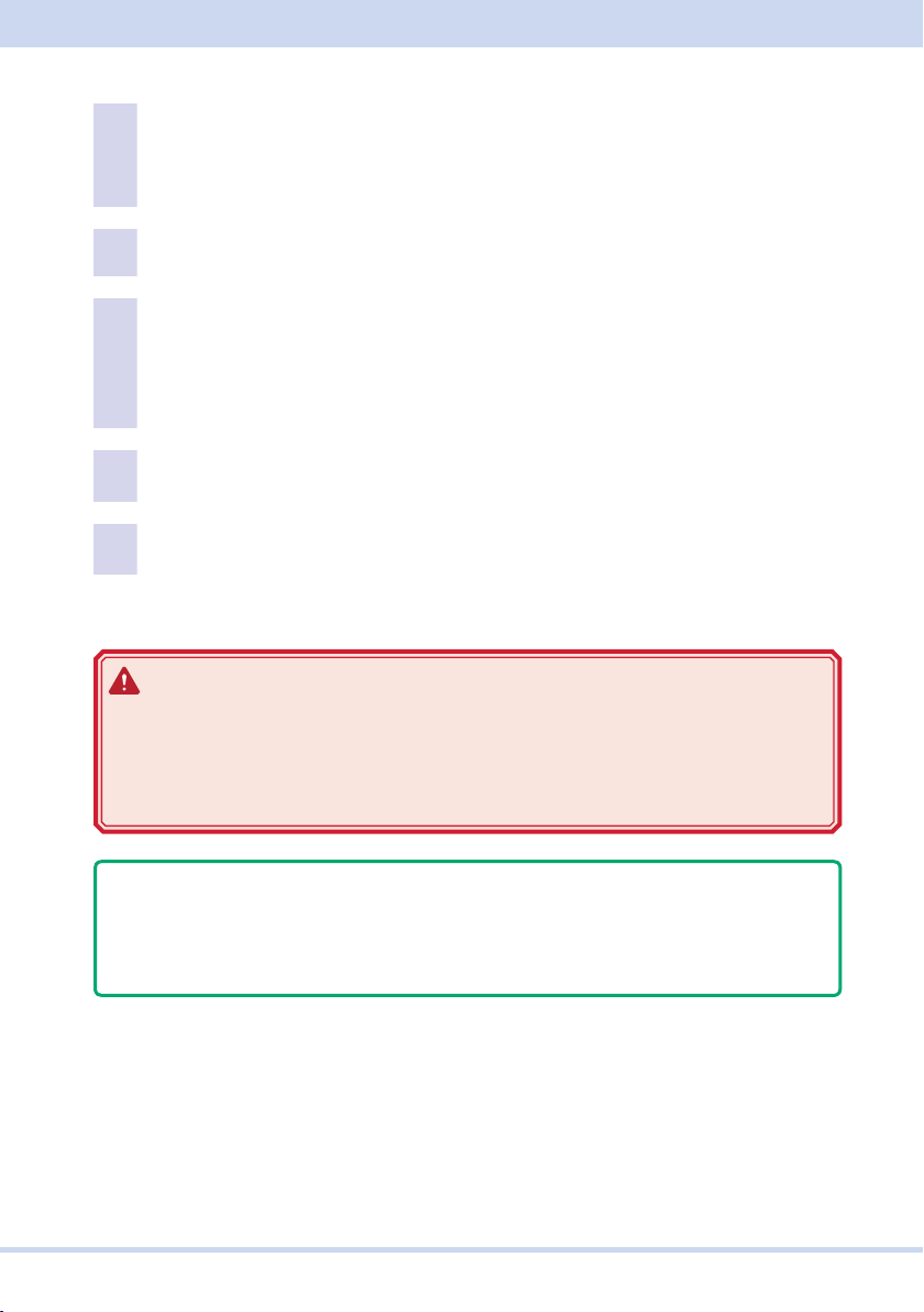
WARNING
Possible damage to the equipment and electric shock. The LAN interface
can be accessed from anywhere on the network that the product is connect-
ed to. Change the security settings if necessary. The security settings that
you can apply are: password protection and IP address access control.
Note
To use the LAN interface, a “SYST:COMM:RLST REM” command must be sent to
set the product to remote mode. To use remote programming, send “SYST:COMM:RLST REM” at the beginning of the program.
■ Service request
The product is equipped with service request and serial polling functions.
37
PCR-WE Interface Manual
Page 38

■ LAN function
Depending on the operations that you perform through your Web browser, the prod-
uct may need to connect to the Internet.
Complies with LXI 1.5 Device Specification 2016
Complies with the SCPI-Telnet, VXI-11, HiSLIP, and SCPI-RAW protocols
Baud rate: 100 Mbps maximum (auto negotiation)
AUTO MDIX
Web browser interface features
Displays measuring instrument information, network information, VISA resource in-
formation, system information, license information
Change network settings, configure security settings, set passwords
Use the simple power supply control application
■ Resetting the LAN settings
You can return all LAN settings except the host name and service name to their facto-
ry default settings.
Press CONFIG (SHIFT+OPR MODE) > COM-I/F (F1) > LAN (F1) > RESET
1
(F4).
Pressing CONFIG (SHIFT+OPR MODE) > COM-I/F (F1) > LAN (F1) > IPv6 (F6) >
RESET (F4) performs the same operation.
A confirmation screen appears.
Press OK (F4).
2
The interface setting is reset.
To cancel, press CANCEL (F5).
KIKUSUI Electronics Corp.
38
Page 39

Setting Up the Interface
■ Returning the LAN settings to their factory default settings
You can return the LAN settings to their factory default settings.
Press CONFIG (SHIFT+OPR MODE) > COM-I/F (F1) > LAN (F1) > DEFAULT
1
(F4).
Pressing CONFIG (SHIFT+OPR MODE) > COM-I/F (F1) > LAN (F1) > IPv6 (F6) >
DEFAULT (F4) performs the same operation.
A confirmation screen appears.
Press OK (F4).
2
The interface settings are returned to the factory default values.
To cancel, press CANCEL (F5).
■ When using SCPI-Telnet or SCPI-RAW
If you send consecutive setting commands at a high speed, the product reception
buffer may overflow. Either do not send consecutive commandssend query
commands and read the responses at fixed intervalsor reduce the command
transmission frequency. If an error (-363 Input buffer overrun) occurs, close VISA
once, and then open it again to reconnect.
39
PCR-WE Interface Manual
Page 40

Accessing and Operating the Product from a Web Browser (LAN)
You can configure the LAN interface settings from your PCʼs Web browser. Use the
latest browser version.
The website URL is the productʼs IP address with http:// added in front of it.
If a VISA library is in use, a function for searching the VXI-11 measurement instru-
ment with the application supplied by the vendor (National Instruments NI-MAX, Key-
sight Connection Expert, Kikusui KI-VISA Instrument Explorer, or the like) is available.
You can open the Web browser interface by simply searching for the instrument and
clicking the Web link that appears in the search result.
Example: When the IP address is 169.254.7.8
http://169.254.7.8
KIKUSUI Electronics Corp.
40
Page 41
Setting Up the Interface
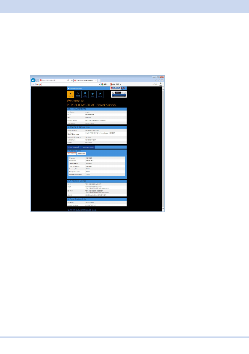
■ Welcome page
When you connect to the Web browser interface, a WELCOME page appears first.
This page shows the measuring instrument information, network information, and
VISA resource (I/O resource) information. Click the navigation menu to go to another
page.
41
PCR-WE Interface Manual
Page 42
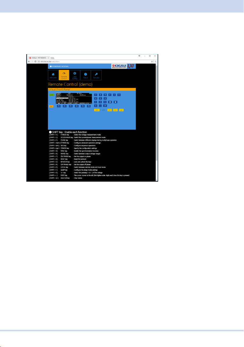
■ Remote Control page
You can remotely control the PCR-WE from a browser. The various buttons have the
same functions as those on the front panel of the PCR-WE.
SHIFT Key
Clicking SHIFT and then a button enables the displayed function.
KIKUSUI Electronics Corp.
42
Page 43
Setting Up the Interface
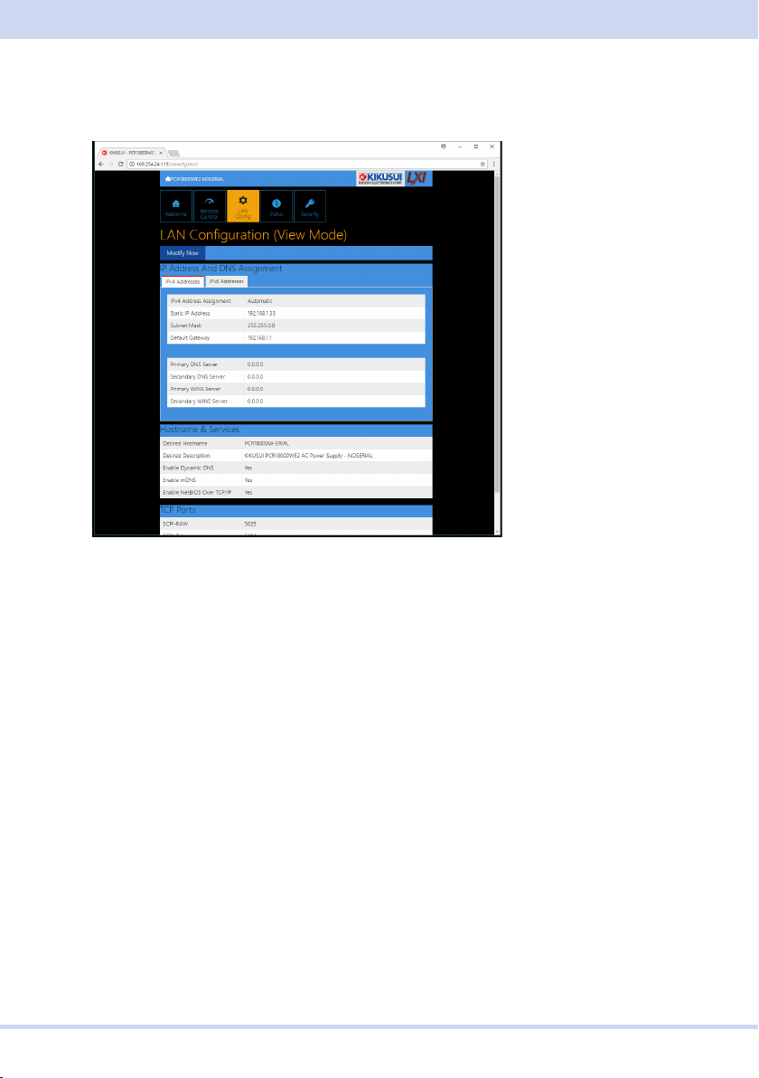
■ LAN Configuration page
You can display (View Mode) and change (Modify Mode) the network settings.
Navigation (View Mode)
Modify Now: Changes to the network setting edit screen (Modify Mode).
Navigation (Modify Mode)
Undo: Returns the edited contents to the state before editing.
Apply: Applies the edited contents.
Reset: Resets the network settings.
Default: Returns the network settings to the factory default settings.
Back to View Mode: Changes to the network setting view screen (View Mode).
43
PCR-WE Interface Manual
Page 44

IP Address Assignment
You can set the IP address. You can choose between automatic assignment and as-
signment of a fixed address.
In the case of automatic assignment of IP address, we recommend using the DHCP
server function using a router as far as possible.
If the DHCP server function is not used, it takes about 60 seconds until determi-
nation that address assignment with DHCP has failed. Then, an address between
169.254.0.0 to 169.254.255.255 is assigned by link local address (Auto-IP).
DNS Server Assignment
Sets the address of the DNS server.
WINS Server Assignment
Sets the address of the WINS server.
Hostname & Services
You can set the host name and so on. If you set the host name, you can use it in
place of the IP address to access the LAN interface. Normally, we recommend that
you select “Enable Dynamic DNS”, “Enable mDNS”, and “Enable NetBIOS Over
TCP/IP”.
If you leave the Hostname and Description boxes empty and click “Apply,” the host
name will be created from the model name and serial number.
TCP Ports (View Mode)
The number of the TCP port in use is displayed. You cannot change the port number.
KIKUSUI Electronics Corp.
44
Page 45
Setting Up the Interface
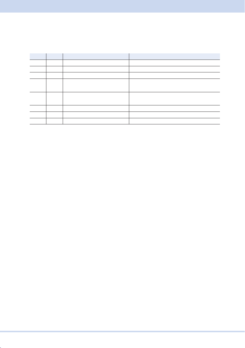
Reset and factory default settings
If you click Reset or Default, network settings are changed as follows.
The items with an X mark are returned to their default values.
Reset Default Parameter Default value
X X Assignment Method DHCP:ON, Auto-IP:ON, Static:OFF
X X DNS Server Assignment 0.0.0.0
X X WINS Server Assignment 0.0.0.0
X Desired Hostname <Model name> - <Last 5 digits of serial
number>
X Desired Description KIKUSUI <model name> AC Power Supply
- <serial number>
X X Enable Dynamic DNS Enable
X X Enable mDNS Enable
X X Enable NetBIOS Over TCP/IP Enable
45
PCR-WE Interface Manual
Page 46
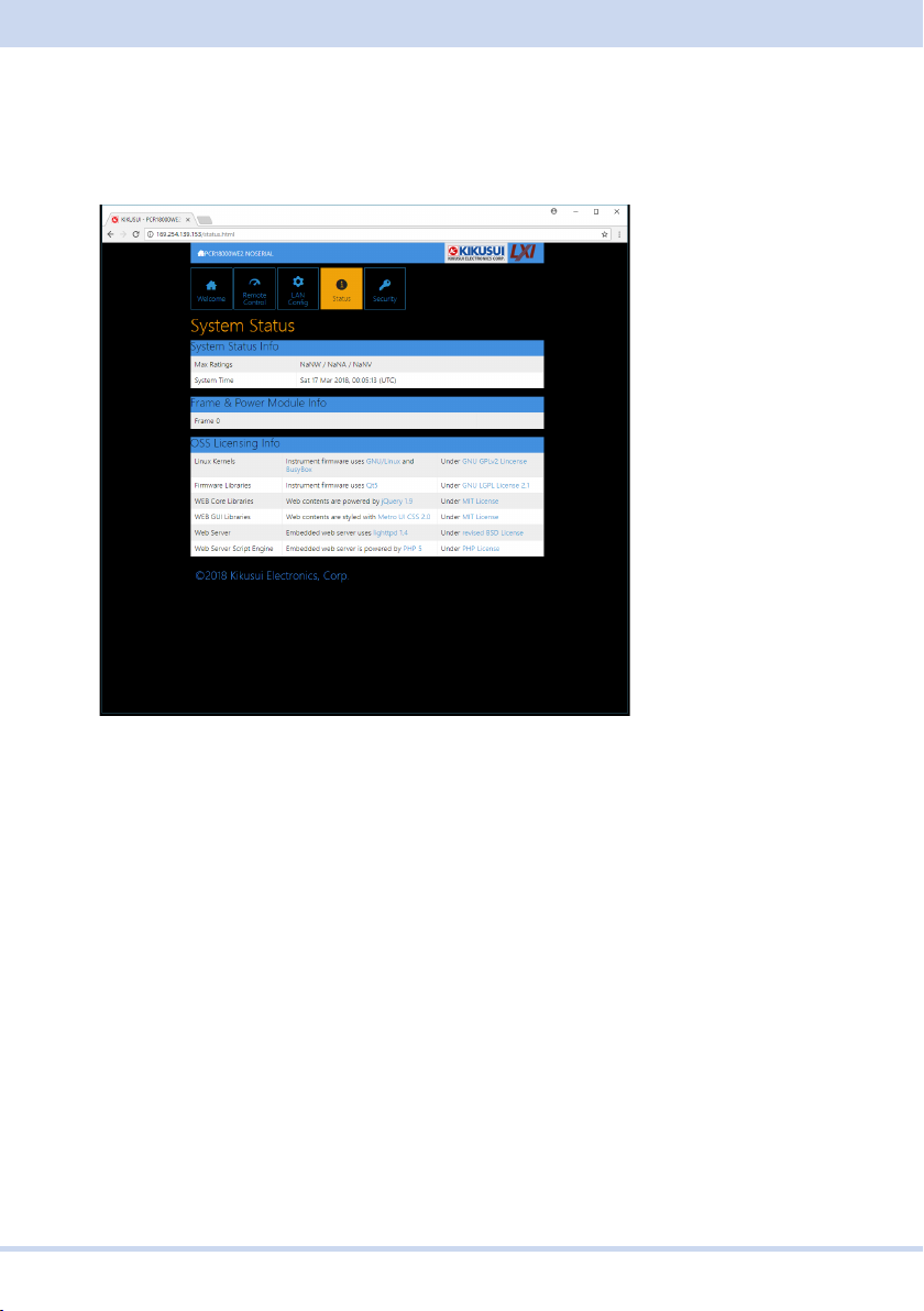
■ System Status page
This page shows the system information and the license information of the open-
source software.
KIKUSUI Electronics Corp.
46
Page 47
Setting Up the Interface
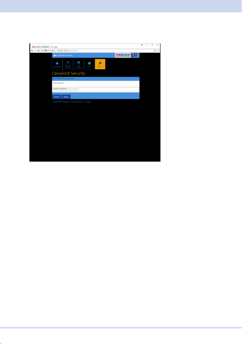
■ Password Security page
You can set and change the password for the Web browser interface here.
When a password has been set, that password is required in order to use the follow-
ing functions.
Remote control from Remote Control page
Editing of LAN Configuration page
Changing/deleting the password
Set New Password
Enter the password.
You can use alphanumeric characters, hyphens, and underscores for the password.
The first character must be an alphabet. You can enter up to 15 characters.
Changing or deleting the password
After the password has been set, the screen for changing the password appears
when you enter the password.
To change the password, enter the present password in “Current Password”, enter
the new password in “New Password” and “Confirm Password”, and then click “Ap-
ply”.
47
PCR-WE Interface Manual
Page 48

To disable password protection, enter the present password in “Current Password”,
leave “New Password” and “Confirm Password” blank, and click “Apply”.
If you forget the password
If you forget the password, reset the LAN interface setting in the CONFIG settings or
initialize the product to its factory default settings.
KIKUSUI Electronics Corp.
48
Page 49
Setting Up the Interface
GPIB (option)
The information in this section is valid only when the optional GPIB interface board is
installed.
■ GPIB connection
Connect the product to a PC using a standard IEEE488 cable.
■ GPIB settings
Press CONFIG (SHIFT+OPR MODE) > COM-I/F (F1) > GPIB (F4).
1
The present GPIB settings are displayed.
To enable GPIB, press ENABLE (F1). To disable it, press DISABLE (F2).
2
Press ADDRESS (F2) to set the GPIB address.
3
The factory default GPIB address is 5.
Press ESC > APPLY (F5).
4
To cancel, press CANCEL (F6).
Turn the PCR-WEʼs POWER switch off and then back on.
5
The settings take effect.
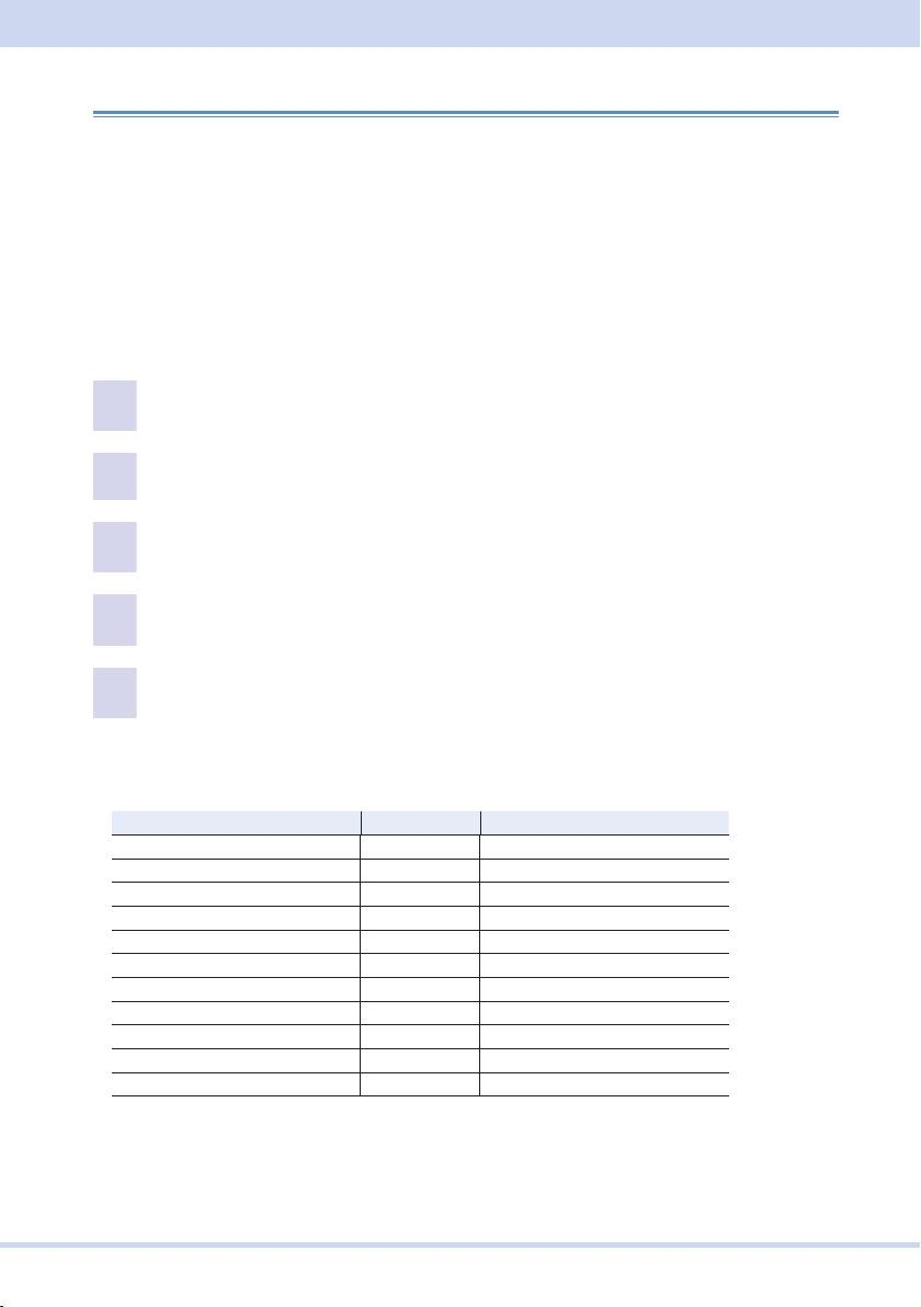
■ GPIB function
Function Subset Description
Source handshaking SH1 Full capability
Acceptor handshaking AH1 Full capability
Talker T8 Function available
Listener L4 Function available
Service request SR0 No capability
Remote local RL0 No capability
Parallel polling PP0 No capability
Device clear DC0 No capability
Device trigger DT0 No capability
Controller C0 No capability
Electrical interface E1 Open-collector driver
49
PCR-WE Interface Manual
Page 50
■ Functional Limitations
The following GPIB-specific functions cannot be used on the PCR-WE/WE2.
Serial polling, parallel polling
Remote local control
Device clear
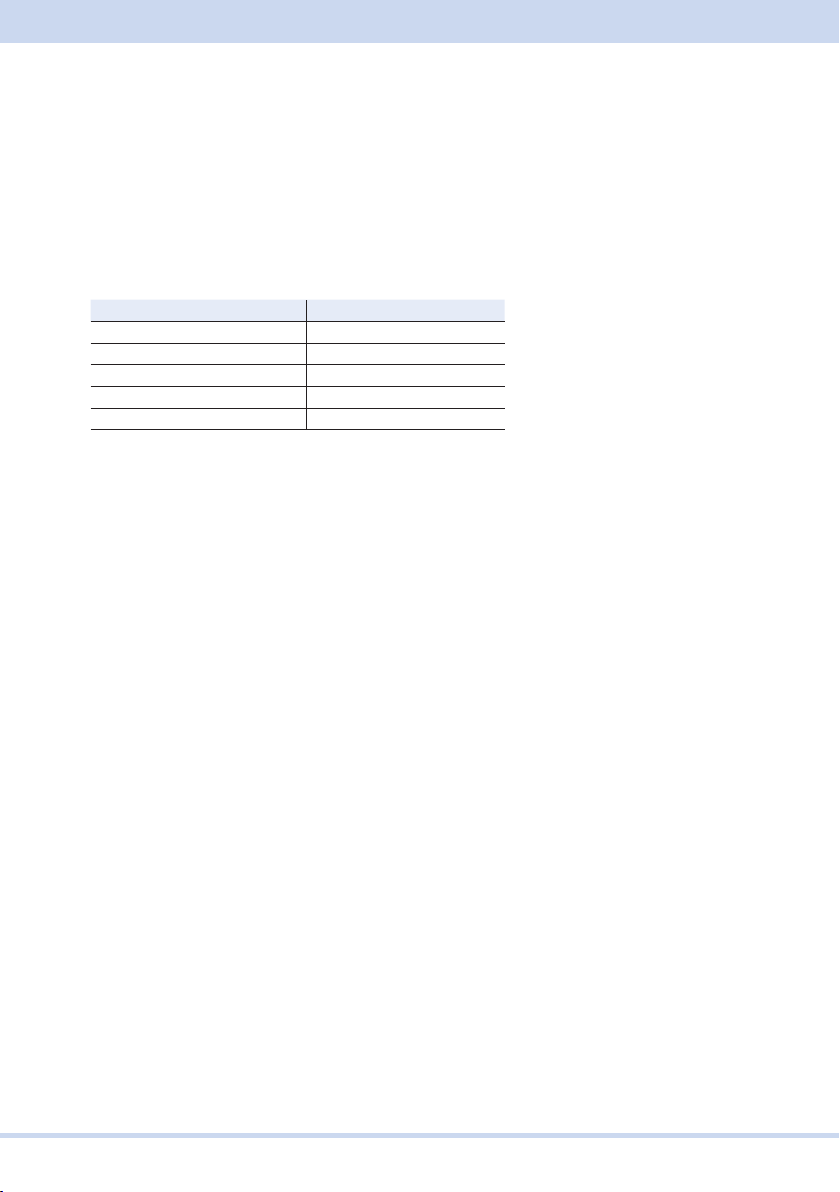
However, for serial polling and remote local control, equivalent functions can be used
through similar commands.
GPIB function Substitute command
Serial Polling *STB?
GET (Group Execute Trigger) *TRG
GTL (Go To Local) SYST:COMM:RLST LOC
REN (Remort Enable) SYST:COMM:RLST REM
LLO (Local Lock Out) SYST:COMM:RLST RWL
KIKUSUI Electronics Corp.
50
Page 51

About Commands
About Commands
The information that is transferred between the controller (PC) and the device (PCR-
WE/WE2 series) is referred to as messages.
This product uses the SCPI language for these messages.
The messages that the PC sends to the product are commands. The messages that
the product sends to the PC are responses.
Command Hierarchy
SCPI is an ASCII-based command language that was designed for test and measur-
ing equipment. The command structure is composed of the common roots and nodes
that are the building blocks of the SCPI subsystem. A command consists of a pro-
gram header, parameters, and punctuation marks.
The following table uses the SOURce subsystem as an example to explain the hier-
archy.
Program header Parameter Node level
SOUR: Root node
FREQ 2nd level
:LIM 3rd level
:UPP <numeric> 4th level
:LOW <boolean> 4th level
VOLT 2nd level
:RANGE 3rd level
:UPP <numeric> 4th level
:AUTO <boolean> 4th level
A colon (:) separates a higher node from a lower node.
51
PCR-WE Interface Manual
Page 52

Command Syntax
In this manual, SCPI commands are expressed in the following format.
MEASure[:SCALar]:CURRent:DC? {<numeric>|MINimum|MAXimum}
SCPI commands are also available in the short form. In the short form, the lowercase
characters in SCPI commands are omitted.
SCPI commands can be sent either in the long form or short form. Because SCPI
commands are not case-sensitive, CURR, CURRent, and curr are all acceptable as
short form notations. In the long form, CURRENT, Current, and current are all accept-
able.
• A space separates a program header and its parameters.
• Multiple parameters are separated by commas.
• Multiple commands are separated by semicolons (compound command).
OUTPut:PHASe:ON:STATe ON;LEVel 90
In the second command, OUTPut:PHASe:ON is omitted. This is possible because that
path is set to OUTPut:PHASe:ON by the first command (OUTPut:PHASe:ON:STATe
ON).
This compound command is equivalent to entering the following commands.
OUTPut:PHASe:ON:STATe ON
OUTPut:PHASe:ON:LEVel 90
If you specify a node that is not defined in the current path, an error will occur.
By using colons and semicolons, you can concatenate commands of different sub-
systems.
SOURce:CURRent MINimum;:MEASure:CURRent:AC?
There are two root nodes in this compound command: SOURce and MEASure.
When the second command or later begins with a colon, the path that was specified
by the previous command is cleared.
• The maximum length of a command that you can transmit on a single line is 128
bytes.
KIKUSUI Electronics Corp.
52
Page 53
About Commands
■ Special symbols
The special symbols that are used in this manual for the SCPI command syntax are
explained below.
• Characters and numbers enclosed by { and } and delimited by “|” indicate that one
of the delimited items is to be selected.
Do not include the { and } symbols in the actual program.
• <> denotes program data.
Do not include the < and > symbols in the actual program.
• [ ] denotes optional data.
When optional data is not sent with the program, the default value is applied.
Do not include the [ and ] symbols in the actual program.
■ Query
You can query the device settings and status.
To make a query, append a question mark to the end of the program header section.
If the query has parameters, insert a space after the question mark, and then write
the parameters.
CURRent? MIN
Response
This is the response to a query. It is a message always sent from the device to the
host PC. It conveys device status or measured value to the PC.
Note
If you want to send two queries on separate lines, send the second query after you
have received the response to the first one.
53
PCR-WE Interface Manual
Page 54
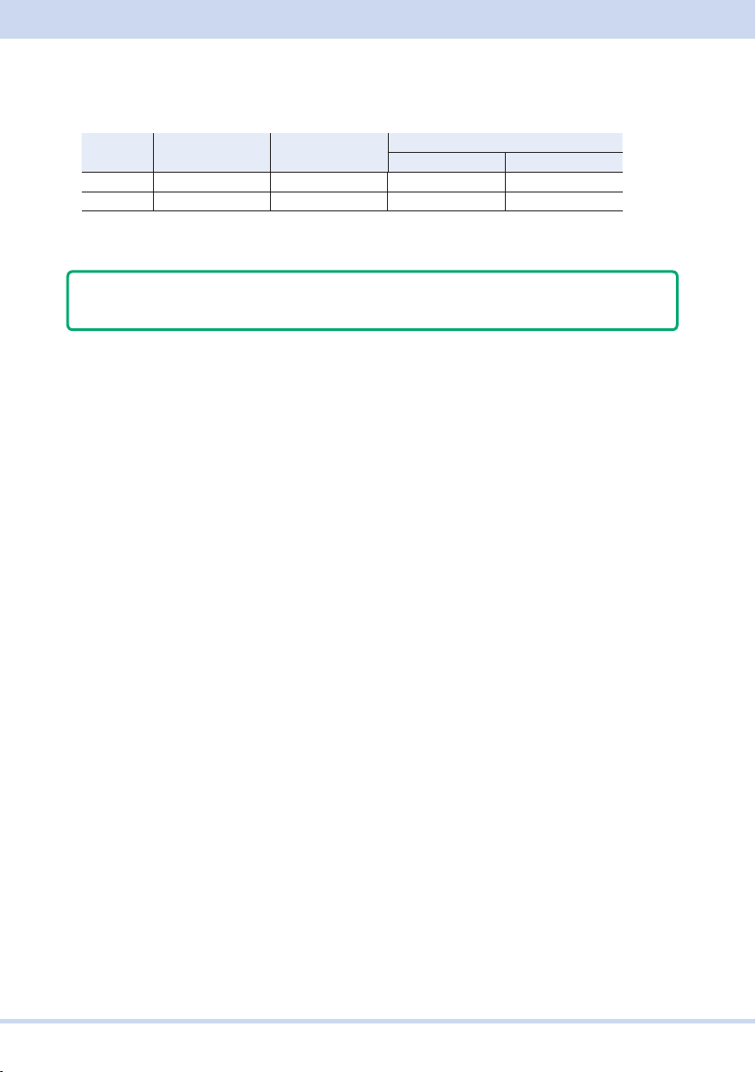
■ Program terminator
All commands must be terminated with a valid terminator.
RS232C USB LAN
VXI-11, HiSLIP SCPI-RAW
Receiving LF LF or EOM LF or END LF
Sending LF LF+EOM LF+END LF
When you terminate a command string, the path is reset to the root level.
Note
CR (ASCII 0x0D) is not a terminator.
■ Common Commands
There are commands that are common to the IEEE-488.2 and SCPI standards for
functions such as resetting devices and performing self-diagnoses. These common
commands start with an asterisk (“*”). These commands may have one or multiple
parameters.
KIKUSUI Electronics Corp.
54
Page 55

Parameters
Parameters
The SCPI parameter format is derived from the program parameter format that is de-
fined in IEEE 488.2.
The program data expression format that the this product uses is shown below.
Non-numeric parameters
String data (String)
String data is used when a series of ASCII characters (20H to 7EH) are requested.
Enclose strings in single (ʼ ʼ) or double quotation ( ) marks. The opening and closing
quotation marks must match (you cannot mix single and double quotation marks).
SYSTem:TZONe "Asia/Tokyo"
If you want to include a quotation mark as part of the string, enter consecutive quota-
tion marks (with no characters between them).
Character data (Character)
Character data is used when only a limited number of values are available for a pro-
gram setting. Responses are returned in short form.
TRIGger:SOURce {BUS|IMMediate}
Boolean data (Boolean)
Boolean data is used to express a condition of 1 or 0, or ON or OFF. Responses are
returned as 1 or 0.
OUTPut {ON|OFF|1|0}
55
PCR-WE Interface Manual
Page 56
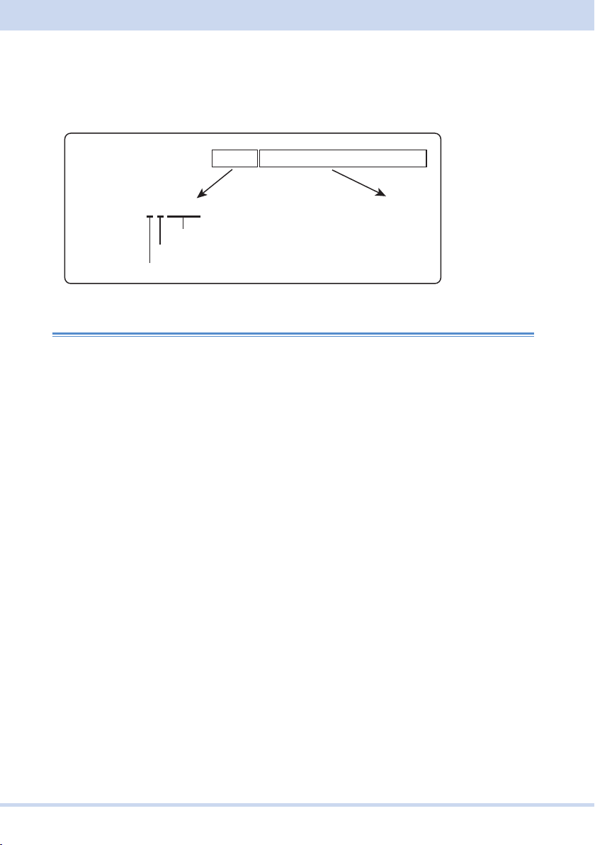
Block data (block)
Arbitrary block data that starts with #.
WAVE:DATA:ARB 5,#481927FFF8000.....7FFFF8000
Example
WAVE:DATA:ARB #481927FFF8000…7FFF…7FFF8000
#48192
Number of connected image data bytes
Number of digits of the number of connected image data bytes
Start of the data block
Image data
(binary format)
8192 bytes
Numeric parameters
NR1
Represents an integer value.
Details are given in the “IEEE 488.2 Standard Digital Interface for Programmable Instrumentation.”
NR2
Represents a real number in floating-point format.
Details are given in the “IEEE 488.2 Standard Digital Interface for Programmable Instrumentation.”
NR3
Represents a real number in scientific notation.
Details are given in the “IEEE 488.2 Standard Digital Interface for Programmable Instrumentation.”
If 380 is returned in the response data, it is returned as +3.80000E+02. Five decimal
places are used.
NRf
NRf is a generic term that includes NR1, NR2, and NR3.
KIKUSUI Electronics Corp.
56
Page 57

Parameters
Numeric
Numeric parameter for values such as the decimal point, optional prefixes, and mea-
surement units.
Numbers are expressed the same as NRf.
MINimum, MAXimum, and the like are available as substitutes for declaring certain
values.
You can also use units such as V, A, and W in numeric parameters.
Special form numeric parameters
The special form numeric parameters MINimum and MAXimum can be used as sub-
stitutes for the actual maximum and minimum values when the parameter is numeric.
The following example sets the overcurrent protection value to the minimum value.
SOURce:CURRent MINimum
You can query the minimum and maximum values for most parameters.
SOURce:CURRent? MAX
SOURce:CURRent? MIN
57
PCR-WE Interface Manual
Page 58

Phase designation (channel list)
When the parameter is numeric, this product allows you to designate the phases you
want to set using the syntax (@chanlist). The INSTrument command settings do not
apply to phase-designated commands.
U phase is (@1), V phase (@2), and W phase (@3).
In the following example, the V phase is set to 130 V.
VOLT 130,(@2)
Multiple phases can be designated at once. To designate U phase (@1) and W phase
(@3)
VOLT 130,(@1,3)
To designate all phases (@1 to @3)
VOLT 130,(@1:3)
Measurement units
The default measurement units are listed below. Commands are accepted even if
measurement units are not specified.
• V (voltage) • A (current) • W (power) • VA (apparent power)
• VAR (reactive power) • DEG (degrees) • HZ (frequency) • H (reactance)
• HR (hours) • MIN (minutes) • S (seconds) • PCT (%)
• OHM (resistance)
The following optional prefixes are supported. If you use optional prefixes, specify the
measurement unit.
• M (milli) • K (kilo) • U (micro)
Note
• The unit symbols in the International System of Units contain lowercase charac-
ters. The IEEE standard uses uppercase characters. SCPI commands are not
case sensitive.
• Commands are accepted whether or not measurement units are specified.
• To enter “µ” in the data, use “U” instead.
KIKUSUI Electronics Corp.
58
Page 59

IEEE 488.2 common commands
IEEE 488.2 common commands
*CLS
Clears all event registers including the status byte, event status, and error queue.
Clears the operation complete standby that was created by the *OPC or *OPC? com-
mand.
Command
*CLS
59
PCR-WE Interface Manual
Page 60

*ESE
Sets the event status enable register that is counted by the event summary bit (ESB)
of the status byte.
Command
*ESE <NRf>
*ESE?
Parameter
Value: 0 to 255
Example: When *ESE 16 is transmitted, bit 4 of the event status enable register is
set. Each time the execution error bit (bit 4) of the event status register is set, the
summary bit (ESB) of the status byte is set.
Response: NR1
KIKUSUI Electronics Corp.
60
Page 61

IEEE 488.2 common commands
*ESR
Queries the event status register. The event status register is cleared when read.
Command
*ESR?
Response: NR1
61
PCR-WE Interface Manual
Page 62

*IDN
Queries the model name and firmware version of the product.
Command
*IDN?
Response
The response to *IDN? is indicated below.
Response example for model PCR3000WE2, serial number WE3RD008, firmware
version 1.00 IFC0.03.0035 IOC0.05.0079
KIKUSUI,PCR3000WE2,WE3RD008,1.00 IFC0.03.0035 IOC0.05.0079
is returned.
KIKUSUI Electronics Corp.
62
Page 63

IEEE 488.2 common commands
*OPC
Sets the OPC bit (bit 0) of the event status register when all the commands that are
in standby have been processed.
See IEEE 488.2-1992 section 12.5.3.
Command
*OPC
*OPC?
Response
Returns “1” when all the commands that are in standby have been processed.
63
PCR-WE Interface Manual
Page 64

*OPT
Queries the optional interface boards that are installed in the product.
During parallel operation, queries the optional interface boards that are installed in
the master unit.
Command
*OPT?
Response
Returns the installed options in comma-separated string format. Returns “0” if no op-
tions are installed.
"GPIB" IB07-PCR-WE GPIB interface board
"500HZLMT" 500 Hz limit model
KIKUSUI Electronics Corp.
64
Page 65

IEEE 488.2 common commands
*PSC
Sets whether the event status enable register and service request enable register are
cleared when the POWER switch is turned on.
Command
*PSC <boolean>
*PSC?
Parameter <boolean>
Value: ON(1) When the POWER switch is turned on, the *ESE and *SRE
settings are cleared.
OFF(0) When the POWER switch is turned on, the *ESE and *SRE
settings are not cleared.
Example
*PSC 0
Response: NR1
65
PCR-WE Interface Manual
Page 66

*RCL
Recalls memory content.
Clears alarms.
Aborts the trigger subsystem operation.
Command
*RCL <NRf>
Parameter
Value: 0 to 9 memory number
Example
*RCL 1
KIKUSUI Electronics Corp.
66
Page 67

IEEE 488.2 common commands
*RST
Resets a portion of the product settings.
Clears alarms. Aborts the trigger subsystem operation.
Clears *OPC and *OPC?. Clears the contents of the preset memory.
Command Value when *RST is transmitted
DISP:PHAS 0
DISP:MMOD:CURR RMS
DISP:MMOD:VOLT RMS
DISP:MMOD:VOLT:LTL OFF
INST OUTP1
INST:NSEL 1
INST:COUP ALL
OUTP OFF
OUTP:IMP OFF
OUTP:IMP:REAC 0
OUTP:IMP:REAL 0
OUTP:PHAS:OFF OFF
OUTP:PHAS:OFF:LEV 0
OUTP:PHAS:ON OFF
OUTP:PHAS:ON:LEV 0
OUTP:PON SAFE
OUTP:SST OFF
OUTP:SST:FALL OFF
OUTP:SST:TIME 0.1
OUTP:SST:TIME:FALL 0.1
SENS:AVER:COUN 1
SENS:CURR:HOLD:TIME 1
SENS:VOLT:AVER:COUN 1
SENS:VOLT:HOLD:TIME 1
CURR MAXimum
CURR:PEAK MAXimum
CURR:PEAK:LOW MAXimum
CURR:PROT:STAT ON
CURR:PROT:TRIP:DEL 10
FREQ 50
FREQ:LIM:LOW 1
FREQ:LIM:UPP 5 000 (500 on the 500 Hz LMT model)
REQ:SYNC OFF
FREQ:SYNC:MODE LINE
FREQ:SYNC:PHAS:DEL 0
FREQ:TRIG 50
FUNC:BANK 0
ROSC INTernal
VOLT 0
VOLT:COMP:MODE DISabled
67
PCR-WE Interface Manual
Page 68

Command Value when *RST is transmitted
VOLT:COMP:RADJ 0
VOLT:COMP:SOFT:CONT AC
VOLT:COMP:SOFT:TERM SENS
VOLT:EXT:INP:EXTDC:ADJ:GAIN 100 (all channels)
VOLT:EXT:INP:EXTDC:ADJ:OFFS 0 (all channels)
VOLT:EXT:INP:EXTDC:APER 0.1
VOLT:EXT:INP:EXTDC:SIGN:POL NORMal
VOLT:EXT:INP:EXTDC:SIGN:SOUR EXTernal
VOLT:EXT:INP:FUNC:MODE OFF
VOLT:EXT:INP:VPR:ADJ:GAIN 10 (all channels)
VOLT:EXT:INP:VPR:ADJ:OFFS 0 (all channels)
VOLT:EXT:INP:VPR:MAP ALL
VOLT:EXT:INP:VPR:STAT OFF
VOLT:LIM:LOW 0
VOLT:LIM:UPP 315
VOLT:LTL 0
VOLT:OFFS 0
VOLT:OFFS:LIM:LOW -445
VOLT:OFFS:LIM:UPP 445
VOLT:OFFS:LTL 0
VOLT:OFFS:TRG 0
VOLT:PROT:LOW 0
VOLT:PROT:PEAK:LOW -489.5
VOLT:PROT:PEAK:UPP 489.5
VOLT:PROT:LOW:STAT OFF
VOLT:PROT:UPP 489.5
VOLT:RANG 157.5
VOLT:RESP MEDium
VOLT:TRIG 0
SYST:CONF:ACC OFF
SYST:CONF:FORM:PSAV:MAX Rated power
SYST:CONF:PHAS:UOFF 0
SYST:CONF:PHAS:UV 120
SYST:CONF:PHAS:UW 240
SYST:SLE OFF
SYST:SLE:TIME 3 600
TRIG:ACQ:SOUR IMMediate
TRIG:PROG:SOUR IMMediate
TRIG:SIM:SOUR IMMediate
TRIG:TRAN:SOUR IMMediate
Command
*RST
KIKUSUI Electronics Corp.
68
Page 69

*SAV
Saves the panel settings to memory.
Command
*SAV <NRf>
Parameter
Value: 0 to 9 memory number
Example
*SAV 1
IEEE 488.2 common commands
69
PCR-WE Interface Manual
Page 70

*SRE
Sets the service request enable register.
The service request enable register can be used to select which summary messages
in the status byte register will perform service requests.
To clear the service request enable register, send *SRE 0. If the register is cleared,
service requests cannot be generated using status information.
Command
*SRE <NRf>
*SRE?
Parameter
Value: 0 to 255
Example: Sending *SRE8 sets bit 3 of the service request enable register. Each time
the summary bit (bit 3) of the QUEStionable status register in the status byte is set, a
service request message is generated.
Response: NR1
KIKUSUI Electronics Corp.
70
Page 71

IEEE 488.2 common commands
*STB
Queries the contents of the status byte register and the MSS (master summary sta-
tus) message.
The response is the same as serial polling only with the exception that the MSS mes-
sage appears in place of the RQS message in bit 6.
Command
*STB?
Response: NR1
71
PCR-WE Interface Manual
Page 72

*TRG
Trigger command.
Executes triggers on the TRANsient trigger group and ACQuire trigger group.
This is a substitute command for IEEE 488.1 get (Group Execute Trigger).
If the device is in a state in which it does not accept triggers, an SCPI error (-211,
“Trigger ignored”) occurs.
See IEEE 488.2-1992 section 10.37.
Command
*TRG
KIKUSUI Electronics Corp.
72
Page 73

IEEE 488.2 common commands
*TST
Executes a self-test.
You can check which error occurred with SYST:ERR? command. See IEEE 488.2-
1992 section 10.38.
Command
*TST?
Response
Returns 0 if there are no errors. Returns an error code if there is a problem.
73
PCR-WE Interface Manual
Page 74

*WAI
Prevents the device from executing subsequent commands until all operations that
are in standby have completed.
Command
*WAI
KIKUSUI Electronics Corp.
74
Page 75

ABORt Command
ABORt Command
This product has four different trigger subsystems (TRANsient, ACQuire, SIMulation,
PROGram).
TRANsient is a subsystem for changing settings.
ACQuire is a measurement trigger subsystem. This subsystem is used to measure
voltage, current, and power.
SIMulation executes power line abnormality simulations.
PROGram runs sequences.
ABOR
Aborts configuration, changes, measurements, and other operations in all trigger sub-
systems (TRANsient, ACQuire, SIMulation, PROGram).
The productʼs trigger state immediately after it turns on is the same as its trigger state
after it receives an ABOR command.
If you send an ABOR command while the PCR is executing measurements, the mea-
sured data is discarded.
You cannot specify a trigger subsystem with the ABOR command. It is always inter-
preted as ALL.
Command
ABORt[:ALL]
75
PCR-WE Interface Manual
Page 76

ABOR:ACQ
Aborts measurement operations.
If you send an ABOR command without initiating, the measured data is not discarded.
Command
ABORt:ACQuire
KIKUSUI Electronics Corp.
76
Page 77

ABOR:PROG
Stops the trigger function of the sequence operation.
Command
ABORt:PROGram
ABORt Command
77
PCR-WE Interface Manual
Page 78

ABOR:SIM
Aborts the trigger function of the power line abnormality simulation.
Command
ABORt:SIMulation
KIKUSUI Electronics Corp.
78
Page 79

ABOR:TRAN
Aborts the trigger function for configuration changes.
Command
ABORt:TRANsient
ABORt Command
79
PCR-WE Interface Manual
Page 80

DISPlay Command
DISP:CONT
Adjusts the screen brightness.
Command
DISPlay:CONTrast <NRf>
DISPlay:CONTrast?
Parameter
Value: 1 to 3 (The default value is 3)
Example
DISP:CONT 2
Response: NR1
KIKUSUI Electronics Corp.
80
Page 81

DISP:PHAS
Selects the phase to display on the panel.
This is invalid for single-phase operation.
Command
DISPlay:PHASe <NR1>
DISPlay:PHASe?
Parameter
Value: 0 All phases (default)
1 U phase
2 V phase
3 W phase
Settings are reset to default values when an *RST command is sent.
Example
DISP:PHAS 1
Response: NR1
DISPlay Command
81
PCR-WE Interface Manual
Page 82

DISP:MMOD:CURR
Sets the current, power, or power factor to display on the screen.
Command
DISPlay:MMODe:CURRent <character>
DISPlay:MMODe:CURRent?
Parameter
Value: RMS Rms current (default)
PEAK Peak current
DC Average current
WATTage Power
VA Apparent power
PF Power factor
TWATtage Total power (single-phase three-wire output
and three-phase output only)
TVA Total apparent power (single-phase three-wire
output and three-phase output only)
TPF Total power factor (single-phase three-wire
output and three-phase output only)
Settings are reset to default values when an *RST command is sent.
Example
DISP:MMOD:CURR RMS
Response: Characters
KIKUSUI Electronics Corp.
82
Page 83

DISPlay Command
DISP:MMOD:VOLT
Sets the voltage (rms value, peak value, average value) to display on the screen.
Command
DISPlay:MMODe:VOLTage <character>
DISPlay:MMODe:VOLTage?
Parameter
Value: RMS Rms voltage (default)
PEAK Peak voltage
DC Average voltage
Settings are reset to default values when an *RST command is sent.
Example
DISP:MMOD:VOLT PEAK
Response: Characters
83
PCR-WE Interface Manual
Page 84

DISP:MMOD:VOLT:LTL
Sets the voltage (phase voltage, line voltage) to display on the screen.
This is invalid for single-phase operation.
Command
DISPlay:MMODe:VOLTage:LTLine[:STATe] <boolean>
DISPlay:MMODe:VOLTage:LTLine[:STATe]?
Parameter
Value: ON(1) Line voltage
OFF(0) Phase voltage (default)
Settings are reset to default values when an *RST command is sent.
Example
DISP:MMOD:VOLT:LTL ON
Response: NR1
KIKUSUI Electronics Corp.
84
Page 85

HCOPy Command
HCOP:SDUM:DATA?
Retrieves the screen capture of the present screen.
Command
HCOPy:SDUMp:DATA?
Response: Block (length: 3 KBytes to 3.5 KBytes)
HCOPy Command
85
PCR-WE Interface Manual
Page 86

INITiate Command
This command cannot be executed simultaneously with the TRANsient, SIMulation,
or PROGram subsystem.
INIT:ACQ
These commands invalidate the present measured data and start a new measure-
ment.
When the trigger source is set to IMM, measurement is started immediately. When
the trigger source is set to BUS, the device waits for a software trigger and then starts
a measurement.
Command
INITiate[:IMMediate]:ACQuire
Related command
TRIG:ACQ
TRIG:ACQ:SOUR
KIKUSUI Electronics Corp.
86
Page 87

INITiate Command
INIT:PROG
Executes a sequence.
When the trigger source is set to IMM, the sequence is executed immediately. When
the trigger source is set to BUS, the device waits for a software trigger and then exe-
cutes the sequence.
Command
INITiate[:IMMediate]:PROGram
Related command
TRIG:PROG
TRIG:PROG:SOUR
87
PCR-WE Interface Manual
Page 88

INIT:SIM
Executes a power line abnormality simulation.
When the trigger source is set to IMM, the sequence is executed immediately. When
the trigger source is set to BUS, the device waits for a software trigger and then exe-
cutes the sequence.
This is invalid when the output is off.
This is invalid if the DC voltage is not zero.
This is invalid when the T3 voltage is set in the H range area or when the present
voltage range is L.
Command
INITiate[:IMMediate]:SIMulation
Related command
TRIG:SIM
TRIG:SIM:SOUR
KIKUSUI Electronics Corp.
88
Page 89

INITiate Command
INIT:TRAN
Starts the trigger function.
If the trigger source is set to IMM, change is immediately started. When the trig-
ger source is set to BUS, the device waits for a software trigger and then starts the
change.
Command
INITiate[:IMMediate]:TRANsient
Related command
TRIG:TRAN
TRIG:TRAN:SOUR
89
PCR-WE Interface Manual
Page 90

INSTrument Command
This command selects the phase that SOURce and MEASure/FETCh commands
apply to for single-phase three-wire output or three-phase output. The INSTrument
command designation does not apply to phase-designated commands.
In the factory default condition, at power-on, and after a *RST or *RCL is sent, all
phases are selected (INST:COUP ALL).
INST/ INST:NSEL
Selects the phase that SOURce and MEASure/FETCh commands apply to.
This does not apply to phase-designated commands.
This is invalid when INST:COUP is set to ALL.
Command
INSTrument[:SELect] <character>
INSTrument[:SELect]?
INSTrument:NSELect <NRf>
INSTrument:NSELect?
Parameter INST command
Value: OUTPut1 U phase (default)
OUTPut2 V phase
OUTPut3 W phase
Parameter INST:NSEL command
Value: 1 U phase (default)
2 V phase
3 W phase
Settings are reset to default values when an *RST command is sent.
Example
INST OUTP1
Response
Returns the designated phase in character format in response to INST?.
Returns the designated phase in NR1 format in response to INST:NSEL?.
KIKUSUI Electronics Corp.
90
Page 91

INSTrument Command
INST:COUP
Sets whether to select all phases.
This is invalid for single-phase output.
Command
INSTrument:COUPle <character>
INSTrument:COUPle?
Parameter
Value: NONE None of the phases are selected.
ALL All phases are selected (default).
Settings are reset to default values when an *RST command is sent.
Example
INST:COUP ALL
Response: Characters
91
PCR-WE Interface Manual
Page 92

LXI Command
LXI:IDEN
Turns the identification display on or off.
When turned on, the LAN indicator blinks in the upper right of the front panel display
of the PCR-WE that is being controlled through the LAN interface.
Command
LXI:IDENtify[:STATe] <boolean>
LXI:IDENtify[:STATe]?
Parameter
Value: ON(1) LAN blinking
OFF(0) LAN lit (Default)
Example
LXI:IDEN ON
Response: NR1
KIKUSUI Electronics Corp.
92
Page 93

MEASure/FETCh Command
MEASure/FETCh Command
The measurement function is mapped to the ACQuire trigger subsystem.
If you use the root node MEASure, the measurement is performed, and then the
measured value is queried. If you use FETC, the measured value is queried without a
measurement being performed.
<meas-item>/<harm-item> is the last node of the command header.
->Tutorial “Measurement (ACQuire)”(p. 321)
93
PCR-WE Interface Manual
Page 94
FETC:<meas-item>/ MEAS:<meas-item>
Queries the scalar measurement data specified with <meas-item>.
Command
FETCh[:SCALar]:<meas-item>? [(@chanlist)]
MEASure[:SCALar]:<meas-item>? [(@chanlist)]
Measurement <meas-item> list of each phase
Phase designation (@chanlist) possible
<meas-item> Description Unit
ALL All (the 25 items below)
CURRent:AC Rms current without a DC component Arms
CURRent:ACDC Rms current Arms
CURRent:AMPLitude:MAXimum Current peak value A
CURRent:AMPLitude:MAXimum:HOLD
CURRent:CREStfactor Current crest factor
CURRent[:DC] Average current A
FREQ Frequency HZ
POWer[:DC] Average power W
POWer:AC[:REAL] Power without a DC component W
POWer:AC:APParent Apparent power without a DC component VA
POWer:AC:REACtive Reactive power without a DC component VAR
POWer:AC:PFACtor Power factor without a DC component
POWer:ACDC[:REAL] Power W
POWer:ACDC:APParent Apparent power VA
POWer:ACDC:REACtive Reactive power VAR
POWer:ACDC:PFACtor Power factor
VOLTage[:DC] Average voltage V
VOLTage:AC Rms voltage without a DC component Vrms
VOLTage:ACDC Rms voltage Vrms
VOLTage:AMPLitude:MAXimum Voltage peak value V
VOLTage:AMPLitude:MAXimum:HOLD Hold value of peak voltage V
LTLVoltage:DC Average line voltage V
LTLVoltage:AC Rms line voltage without a DC component Vrms
LTLVoltage:ACDC Rms line voltage Vrms
LTLVoltage:AMPLitude:MAXimum Line voltage peak value V
Hold value of peak current A
KIKUSUI Electronics Corp.
94
Page 95
MEASure/FETCh Command
Measurement <meas-item> list of the total values of all phases
Phase designation (@chanlist) not possible
<meas-item> Description Unit
POWer[:DC]:TOTal Total average power W
POWer:AC[:REAL]:TOTal Total power without a DC component W
POWer:AC:APParent:TOTal Total apparent power without a DC component VA
POWer:AC:REACtive:TOTal Total reactive power without a DC component VAR
POWer:AC:PFACtor:TOTal Total power factor without a DC component
POWer:ACDC[:REAL]:TOTal Total power W
POWer:ACDC:APParent:TOTal Total apparent power VA
POWer:ACDC:REACtive:TOTal Total reactive power VAR
POWer:ACDC:PFACtor:TOTal Total power factor
Response
Returns the measurement of the designated phase in NR3[,<NR3>...] format in re-
sponse to FETC:<meas-item>? [(@chanlist)]/ MEAS:<meas-item>? [(@chanlist)].
Returns the measurement of the phase designated by the INST command in
NR3[,<NR3>...] format in response to FETC:<meas-item>?/ MEAS:<meas-item>?.
Returns 0 in response to a line voltage query during single-phase output.
Returns the measured values in the <meas-item> list order in comma-separated
NR3 format in response to FETC:ALL?/MEAS:ALL?. If you specify several phases,
the measured values of the first specified phase are returned in the <meas-item>
list order. Then, the measured values of the next specified phase are returned in
the <meas-item> list order.
Example
INST:NSEL 1;COUP NONE
FETC:CURR?
INST:COUP ALL
FETC:CURR?
FETC:CURR? (@2)
FETC:CURR? (@1:3)
FETC:ALL? (@1)
FETC:ALL?
Returns the average current of the U phase.
Returns the average currents of all phases.
Returns the average current of the V phase.
Returns the average currents of all phases.
Returns all scalar measurements (25 items, excluding the total
value) of the U phase.
Returns all scalar measurements (25 items 3, excluding the total
value) of all phases.
95
PCR-WE Interface Manual
Page 96
FETC:ARR:<harm-item>?/ MEAS:ARR:<harm-item>?
Queries the harmonic data specified with <harm-item>.
Command
FETCh:ARRay:<harm-item>? [(@chanlist)]
MEASure:ARRay:<harm-item>? [(@chanlist)]
Measurement <harm-item> list of each phase
Phase designation (@chanlist) possible
0th to 50th
<harm-item> Description Unit
CURRent:HARMonic[:AMPLitude] Harmonic current Arms
CURRent:HARMonic:PHASe Harmonic current phase Deg
CURRent:HARMonic:THD Total current harmonic distortion PCT
VOLTage:HARMonic[:AMPLitude] Harmonic voltage Vrms
VOLTage:HARMonic:PHASe Harmonic voltage phase Deg
VOLTage:HARMonic:THD Total voltage harmonic distortion PCT
Response
Returns the measurements (0th to 50th) of the designated phase in a com-
ma-separated NR3 format in response to FETC:ARR:<harm-item>? [(@chanlist)]/
MEAS:ARR:<harm-item>? [(@chanlist)].
Returns the measurements (0th to 50th) of the phase designated by the INST
command in a comma-separated NR3 format in response to FETC:<meas-item>?/
MEAS:<meas-item>?.
Returns the measurements (0th to 50th) of the U phase in a comma-separated
NR3 format when multiple phases are designated. Then, the V-phase measure-
ments and W-phase measurements are returned in the same manner.
Example
INST:NSEL 1;COUP NONE
FETC:ARR:CURR:HARM?
FETC:ARR:CURR:HARM? (@2)
FETC:ARR:CURR:HARM? (@1:3)
KIKUSUI Electronics Corp.
Returns the harmonic current of the U phase.
Returns the harmonic current of the V phase.
Returns the harmonic currents of all phases.
96
Page 97

MEMory Command
MEMory Command
MEM:REC
Recalls contents saved in the ABC memory.
You can view the contents that are stored in memory by using the MEM:REC:PREV
command.
Command
MEMory:RECall[:IMMediate] <NRf>
Parameter
Value: 1 Memory A
2 Memory B
3 Memory C
97
PCR-WE Interface Manual
Page 98

MEM:REC:CONF
Sets whether to the memory content is to be confirmed before recalling the ABC
memory from the panel.
Command
MEMory:RECall:CONFirmation[:STATe] <boolean>
MEMory:RECall:CONFirmation[:STATe]?
Parameter
Value: ON(1) The memory content is to be confirmed (default).
OFF(0) The memory content is not to be confirmed.
Example
MEM:REC:CONF ON
Response: NR1
KIKUSUI Electronics Corp.
98
Page 99

MEMory Command
MEM:REC:PREV
Displays the contents that are stored in the ABC memory.
Command
MEMory:RECall:PREView? <NRf>
Parameter
Value: 1 Memory A
2 Memory B
3 Memory C
Response
Returns the following items that are stored in the specified ABC memory. The items
are returned in order in a comma-separated format.
For single-phase output, AC voltage <NR3>, DC voltage <NR3>, frequency
<NR3>, waveform bank number <NR1>
For single-phase three-wire output, U phase AC voltage<NR3>, V phase AC
voltage<NR3>, U phase DC voltage<NR3>, V phase DC voltage<NR3>, frequen-
cy<NR3>, U phase waveform bank number<NR1>, V phase waveform bank num-
ber<NR1>
For three-phase output, U phase AC voltage<NR3>, V phase AC voltage<NR3>,
W phase AC voltage<NR3>, U phase DC voltage<NR3>, V phase DC volt-
age<NR3>, W phase DC voltage<NR3>, frequency<NR3>, U phase waveform
bank number<NR1>, V phase waveform bank number<NR1>, W phase waveform
bank number<NR1>
99
PCR-WE Interface Manual
Page 100

MEM:SAVE
Saves the frequency, AC voltage, DC voltage, and waveform bank number to memo-
ry.
Command
MEMory:SAVE[:IMMediate] <NRf>
Parameter
Value: 1 Memory A
2 Memory B
3 Memory C
KIKUSUI Electronics Corp.
100
 Loading...