

Page 1
PART NO. IB02390H
Oct. 2017
User’s Manual
AC Power Supply PCR-LE series
PCR500LE
PCR1000LE
Checking the Package Contents 3
Features 3
About the PCR-LE Documentation 4
PCR-LE Series models 6
Precautions Concerning Installation 6
Precautions When Moving the Product 6
Handling the Terminal Block Tray (PCR1000LE - PCR9000LE) 7
Connecting the PCR500LE Power Cord 8
Connecting the power cord (PCR1000LE - PCR 9000LE) 9
Turning the Power On 9
Connecting the Load 10
- Basic -
Front Panel 13
Rear Panel 15
Panel Operation Basics 16
Selecting the Output Mode 20
Setting the Output Voltage 21
Setting the Frequency 26
Turning Output On and Off 26
Displaying Measured Values 28
Limit Values and Protection Functions30
Setting Limits31
Using Protection Functions 36
Using Memory 38
PCR2000LE
PCR3000LE
PCR4000LE
PCR6000LE
PCR9000LE
- Advanced -
Using the Synchronization Function 45
Using the Voltage compensation Function 46
Using Power Line Abnormality Simulations 51
Using the Sequence Function 54
Using the Harmonic Current Analysis Function 63
Generating Special Waveforms (Waveform bank) 64
Setting the Output Impedance 65
Setting Soft Starts (The voltage rise time) 65
Fixing the Internal Vcc 66
Selecting the Response 66
Using the Power Management Functions 67
Controlling the Output Using External Analog Signals 68
- Specications -
Main Unit Specications 77
Option Specications 84
Outline Drawings 86
- Appendix -
Glossary 91
Operating Characteristics 93
About the output and the load 94
Peak hold current measurement 102
Sequence tutorial 103
Option 115
Factory Default Settings (Initialization) 122
Maintenance 125
Troubleshooting 126
Alarms and Trouble 128
Error Message 131
Index 132
Page 2

This manuals are intended for users of the PCR-LESeries AC
Power Supply and their instructors.
Explanations are given under the presumption that the reader
has knowledge related to electric safety tests.
Every effort has been made to ensure the accuracy of this
manual. However, if you have any questions or find any errors
or omissions, please contact your Kikusui agent or distributor.
Firmware version of the product to which this
manual applies
This manual applies to PCR-LEs with firmware version 5.0x.
When making an inquiry about the product, please provide us
with the following information.
Model (indicated at the top section on the front panel)
Firmware version
Serial number (indicated at the bottom section on the rear
panel)
Copyright 2012 Kikusui Electronics Corporation
Page 3
Thank you for purchasing the PCR-LE Series AC Power Supply.
If necessary, attach to the product.
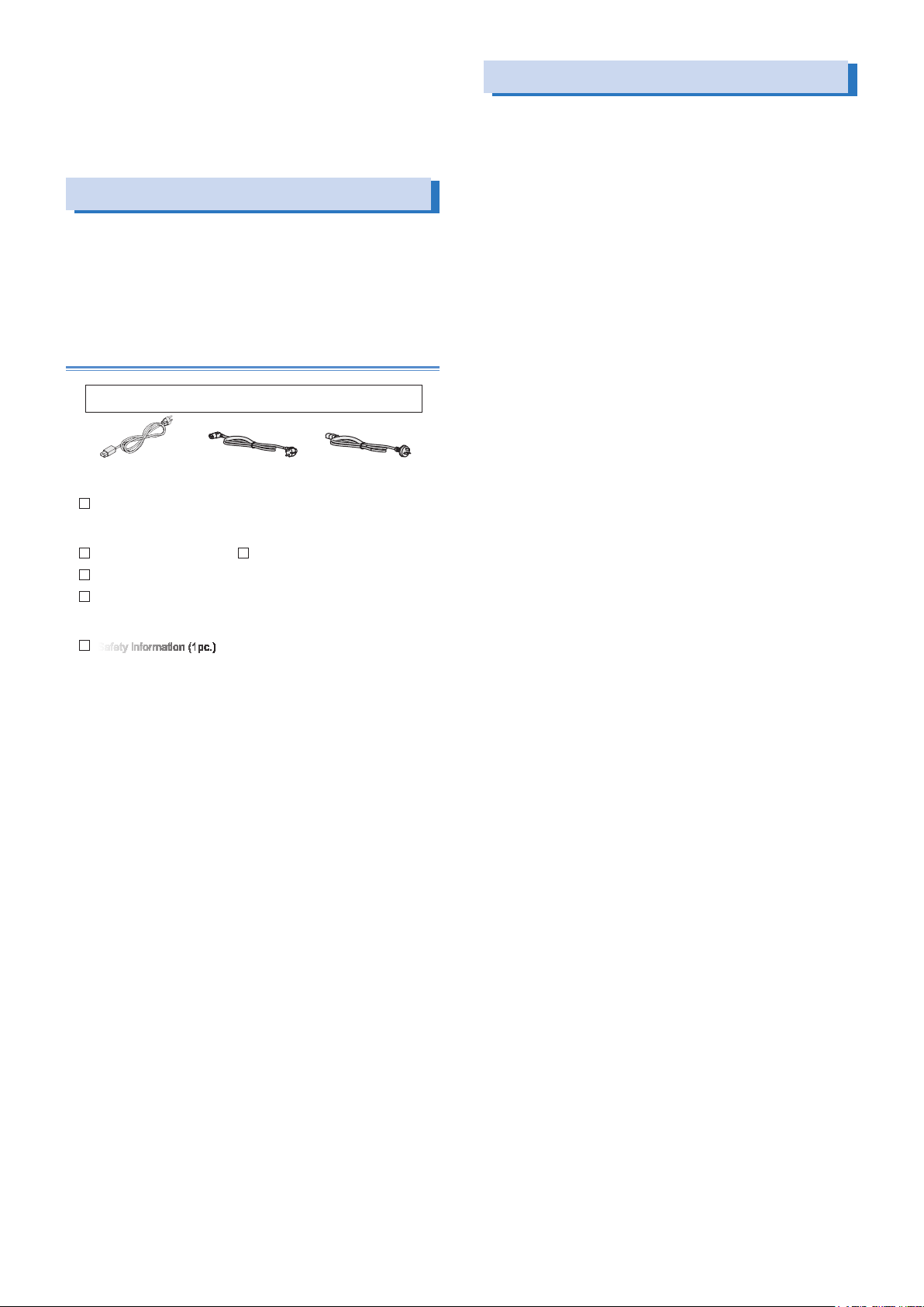
The attached power cord varies depending on the input-voltage-range setting of
The PCR-LE Series is the evolution of Kikusui’s proven PCR-LA
Series of AC power supplies. The power supply contains a combination of a high-speed linear amplifier and an arbitrary waveform
synthesizer to ensure high precision.
Checking the Package Contents
When you receive the product, check that all accessories are included and that the accessories have not been damaged during
transportation. If any of the accessories are damaged or missing,
contact your Kikusui agent or distributor. We recommend that you
save all packing materials, in case the product needs to be transported at a later date.
Accessory
the power supply at the time of shipping.
or
Rated voltage: 125 Vac
PLUG: NEMA5-15
[85-10-1030] [85-AA-0005] [85-10-0790]
Power cord (1pc.)
This is only included with the PCR500LE.
Setup Guide (1pc.)
CD-ROM (1 pc.)
Quick Reference
(Japanese:1 pc.
English: 1 pc.)
Safety information (1pc.)
Rated voltage: 250 Vac
PLUG: CEE7/7
Heavy object warning label
Not included with the PCR500LE
PCR1000LE: A8-900-154
PCR2000LE: A8-900-155
PCR3000LE: A8-900-157
PCR4000LE: A8-900-157
PCR6000LE: A8-900-158
PCR9000LE: A8-900-158
or
Rated voltage: 250 Vac
PLUG: GB1002
Features
The PCR-LE Series is equipped with the following features.
• Various power supply simulations
Power line abnormalities such as outages and voltage dips can
be simulated. This is a basic feature for power-supply-environment testing.
• Various measurements
The rms voltage and current, the peak voltage and current, the
active power, apparent power, and power factor of the output
can be measured. Harmonic analysis (up to the 40th harmonic)
can be performed on the output current.
• DC output
The PCR-LE Series can generate DC output and AC + DC out-
put. This makes it possible to use the PCR-LE Series in a wide
variety of fields, including chemistry and physics.
• Sequences
The output voltage, frequency, and waveform can be changed
over time. Power-supply-environment testing can be automated.
In addition to the AC output sequences, DC output and AC + DC
output sequences are also available. A variety of standard tests
can also be performed.
• Sensing and regulation adjustment
Even if the load device is at a remote location, the PCR-LE Series
can stabilize the voltage across the load by correcting for voltage drops.
There are two types of sensing: hard sensing and soft sensing.
The different types of sensing are used depending on the load
conditions and how you will use the PCR-LE Series.
• Output current control
The output limit function can be used to limit the output current
(rms) to a fixed value to perform continuous operation. Continuity
tests on electrical equipment (such as switchboards, breakers,
and wiring devices) can be performed under stable conditions.
• Power management function (power saving function)
A sleep function, which turns the power units off to reduce power
consumption when output is not generated for the specified
length of time, and a power-saving function, which operates the
power units at the bare minimum settings as required by the supply load, are available.
• Memory function
Up to 99 entries of output frequency, voltage (AC or DC), and
waveform bank settings can be saved to the internal memory.
The contents of internal memory, panel settings, power line ab-
normality simulations, sequence data, and waveform bank data
can be saved to a USB memory device.
• External communications
The PCR-LE Series can be controlled remotely through its
RS232C interface. If an optional interface board is used, the
PCR-LE Series can be controlled remotely through USB, GPIB,
and LAN interfaces.
• Single-phase, three-wire output/ Theree-phase output (Optional)
Use of the optional 2P05-PCR-LE allows the outputs of two PCR-
LEs to be connected in series for use as single-phase, three-wire
system power supplies. Use of the optional 3P05-PCR-LE allows
the outputs of three PCR-LEs to be connected in star connection
for use as three-phase system power supplies
• Master-Slave parallel control (Optional)
The PD05M-PCR-LE/PD05S-PCR-LE option enables the PCR-LE
Series to be operated in parallel (except for the PCR500LE and
PCR1000LE; up to five units or within 27 kVA of power; different
models can be mixed).
• External analog signal control (optional)
The EX05-PCR-LE/EX06-PCR-LE option enables you to control
the PCR-LE2 Series output using external analog signals.
.
PCR-LE series 3
Page 4
About the PCR-LE Documentation
These manuals are intended for users of the PCR-LE Series AC
Power Supply and their instructors.
Explanations are given under the presumption that the reader has
knowledge related to electric safety tests.
You can view the PDF file using Adobe Reader 6.0 or later.
The HTML can be viewed using the following browser.
Browser: Microsoft Internet Explorer 9.0 or later
Every effort has been made to ensure the accuracy of this manual.
However, if you have any questions or find any errors or omissions,
please contact your Kikusui agent or distributor.
If you find any misplaced or missing pages in this manual, it will be
replaced. If the manual gets lost or soiled, a new copy can be provided for a fee. To replace or purchase a manual, please contact
your Kikusui agent or distributor. At that time, inform your agent or
distributor of the “Part No.” written on the front cover of this manual.
After you have finished reading this manual, store it so that you can
use it for reference at any time.
Notations used in the PCR-LE manual
In the PCR-LE manual, the PCR-LE Series AC Power Supply is also
referred to as the PCR-LE Series and the PCR-LE.
The term “PC” is used to refer generally to both personal computers and workstations.
The screen captures used in this manual may differ from the actual screens that appear on the PCR-LE. The screen captures are
merely examples.
The following markings are used in the explanations in the manual.
Contents of the Included CD-ROM
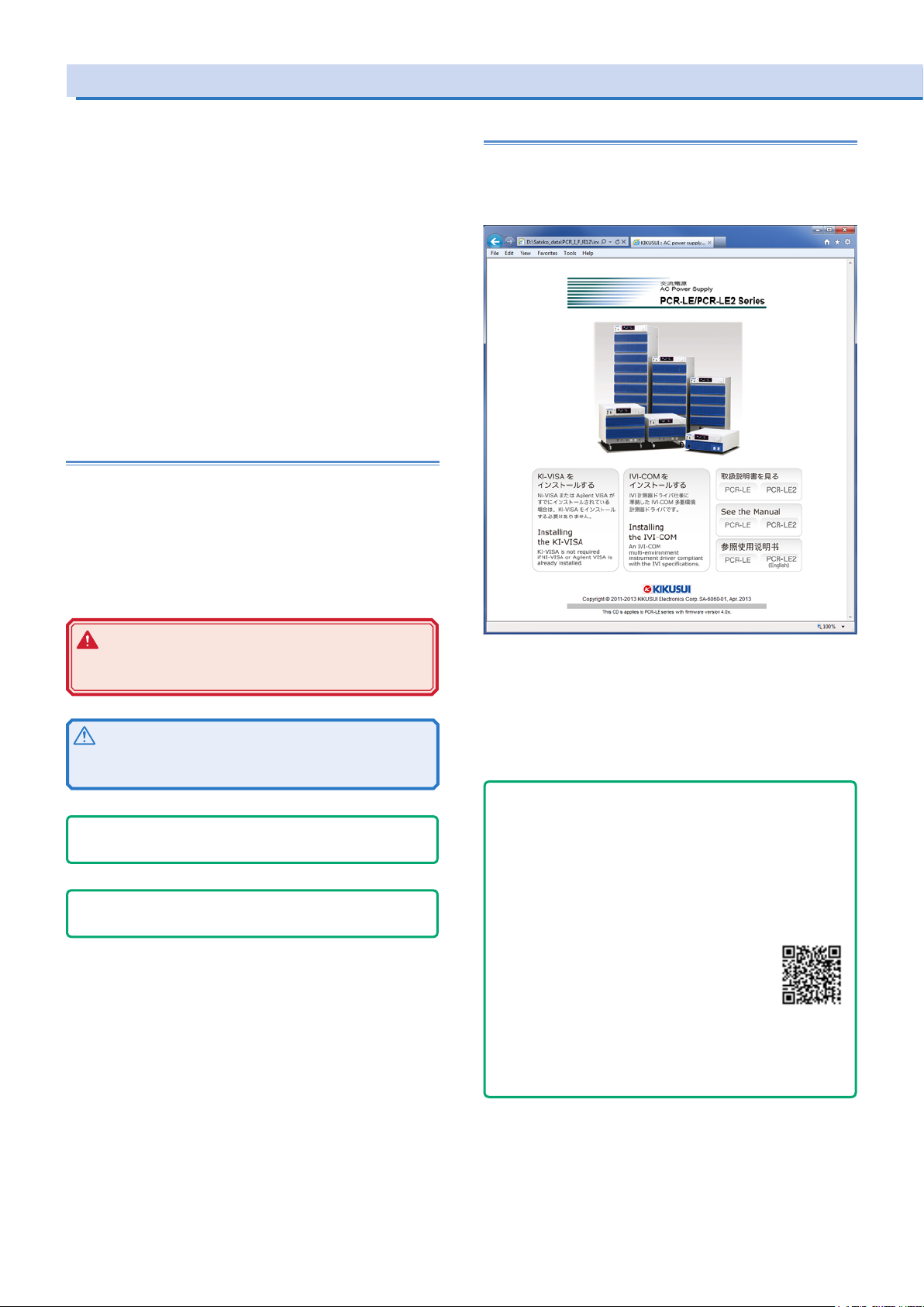
Put the included CD-ROM into the CD-ROM drive. In a few moments, a start window will appear. If the start window does not
appear, open the CD-ROM folder in Windows Explorer, and then
double-click index.html to display the start window.
WARNING
Indicates a potentially hazardous situation which, if ignored, could result in death or serious injury.
CAUTION
Indicates a potentially hazardous situation which, if ignored,
may result in damage to the product or other property.
- Note -
Indicates information that you should know.
- DESCRIPTION -
Explanation of terminology or operation principle.
(SHIFT+key name)
Indicates an operation that requires you to press a key indicated
in blue characters (the lower row of text to the left of the key)
while holding down the SHIFT key.
Accompanying CD-ROM contains following the items.
• KI-VISA x.x.x
• IVI-COM
• Operation Manual
Click the “PCR-LE” of "See the Manual" to move to the Manual
page.
- Tips -
How to view ePub les on a tablet
To view an ePub file on a tablet, an ePub reader (e.g.,
iBooks, Himawari Reader) must be installed in the tablet.
You can download ePub readers for free.
There are several ways to copy ePub les to your tablet,
but we recommend that you download them from the
Kikusui Electronics Corporation website.
1. Using a browser on your tablet, visit
Kikusui Electronics Corporation website’s
Operation Manual Database (http://www.
kikusui.co.jp/en/download/), and search for
your PCR-LE series.
2. Tap the appropriate ePub le to download it.
When an ePub le is downloaded to your tablet, you can
view it even when the tablet is not connected to the Web.
4 PCR-LE series
Page 5

Documentation Structure
The PCR-LE Series manual comprises the following documentation.
User’s Manual -Basic-
• Front panel and Rear panel
• Panel Operation Basics
• Selecting the Output Mode
• Setting the Output Voltage/ Frequency
• Turning Output On and Off
• Displaying Measurement Values
How to switch the display of measured value.
• Setting Limits
Limits can be placed on the PCR-LE output voltage setting and
frequency setting. They prevent damage to the load caused by
mistaken operations and limit the current that flows through the
load. You can set limits in advance according to the load conditions.
• Using Protection Functions
The PCR-LE has the following protection functions.
Input voltage drop protection
Overheat protection (OHP)
Overload protection
Internal semiconductor protection (OCP)
Output undervoltage protection (UVP)
Output overvoltage protection (OVP)
• Using Memory
You can store data to the PCR-LE’s internal memory and save
data to a USB memory device.
User’s Manual -Specications-
Specifications contains the electrical specifications and outline
drawings.
User’s Manual -Appendix-
• Glossary, Operation Characteristics, Output and load
• Peak hold current measurement
• Sequence tutorial
• Option
• Factory Default Settings
• Maintenance
• Troubleshooting
• Alarms and Trouble
• Error Message
Setup Guide (This guide)
This guide is intended for first-time users of the product. It gives an
overview of the product, connecting procedures, etc. Please read
through and understand this guide before operating the product.
Quick Reference
The quick reference briefly explains the panel description and the
basic operation of the product.
Safety information
This document contains general safety precautions for this product.
Keep them in mind and make sure to observe them.
Programming Sheet
• Table for Recording Power Line Abnormality Simulation Operation Settings (XLS)
• Table for Recording Sequence Operation Settings (XLS)
User’s Manual -Advanced-
• Using the synchronization Function
The synchronization function synchronizes the frequency and
phase of the PCR-LE output voltage with a 50 Hz or 60 Hz input
power supply.
• Using the Voltage Compensation Function
The compensation function compensates for voltage drops in the
load cables when the load is connected to the PCR-LE over a
long distance.
• Using Power Line Abnormality Simulations
In AC mode, you can simulate power supply line errors by stop-
ping the PCR-LE output and decreasing and increasing the voltage (to simulate voltage dips and pops).
• Using the Sequence Function
A sequence is a series of settings - values such as the output
voltage, frequency, and time - that are saved in advance and
are then recalled and automatically carried out in order at a later
time.
• Using the Harmonic Current Analysis Function
You can perform harmonic analysis of the output current.
• Generating Special Waveforms (Waveform bank)
You can generate peak-clipped sine waveforms.
• Setting the Output Impedance
The PCR-LE output impedance (output resistance) is approxi-
mately 0 Ω. Commercial power supplies have an impedance
(resistance) of several milliohms to several ohms. You can set
the PCR-LE output impedance. This enables you to simulate
the same environment as that which is provided by commercial
power supplies.
• Setting Soft Starts (The voltage rise time)
To prevent the output from being turned off (the alarm from be-
ing activated) and the voltage from dropping due to the load
device’s inrush current that exceeds the rated capacity of the
PCR-LE, you can control the inrush current by having the output
voltage rise gradually when the output is turned on.
• Fixing the Internal Vcc
To minimize loss in the linear amplifier section, the PCR-LE au-
tomatically adjusts the linear amplifier supply voltage (Vcc) to a
level that is suitable for the output voltage. You can fix the Vcc
voltage of the PCR-LE. This is useful when you want to prioritize
the output voltage response over the product’s efficiency.
• Selecting the Response
The PCR-LE uses a high-speed amplifier. Depending on the load
circuits (especially in the case of capacitive loads) and the wiring
conditions, the output may become unstable may oscillate. You
can set the response speed of the internal amplifier according to
the load conditions and how you will use the PCR-LE.
• Using the Power Management Functions
The PCR-LE has the following two power management functions:
a sleep function and a power-saving function
• External analog signal control (optional)
You can use the optional analog signal interface board to control
the product with external analog signals.
Communication Interface Manual
This manual contains details about remote control.
Interface manual is written for readers with sufficient basic knowl-
edge of how to control instruments using a personal computer.
PCR-LE series 5
Page 6
PCR-LE Series models
PCR1000LE/ PCR2000LE
PCR3000LE/ PCR4000LE/ PCR6000LE/ PCR9000LE
Stopper
The PCR-LE Series generates single-phase output. The following
models are available
Model Rated output
PCR500LE 500 VA 5 A 2.5 A
PCR1000LE 1 kVA 10 A 5 A
PCR2000LE 2 kVA 20 A 10 A
PCR3000LE 3 kVA 30 A 15 A
PCR4000LE 4 kVA 40 A 20 A
PCR6000LE 6 kVA 60 A 30 A
PCR9000LE 9 kVA 90 A 45 A
capacity
Precautions Concerning Installation
When installing this product, be sure to observe the precautions
provided in “Precautions Concerning Installation Location” in the
Safety information manual. Items specific to this product are given
below.
When you install the product, be sure to observe the temperature
●
and humidity ranges indicated below.
Operating temperature range: 0 °C to 50 °C (32 °F to 122 °F)
Operating humidity range: 20 %rh to 80 %rh (no condensation)
When you store the product, be sure to observe the temperature
●
and humidity ranges indicated below.
Storage temperature range: -10 °C to 60 °C (14 °F to 140 °F)
Storage humidity range: 90 %rh or less (no condensation)
Allow at least 20 cm of space between the air inlet/outlet and the
●
wall (or obstacles).
Fix PCR6000LEs and PCR9000LEs to the floor using L-shaped
●
or other similar brackets.
Base Hold Angles (OP03-KRC) are available as options.
Maximum output current
With 100 V output With 200 V output
Precautions When Moving the Product
Note the following points when moving the product to the installation location or when transporting the product.
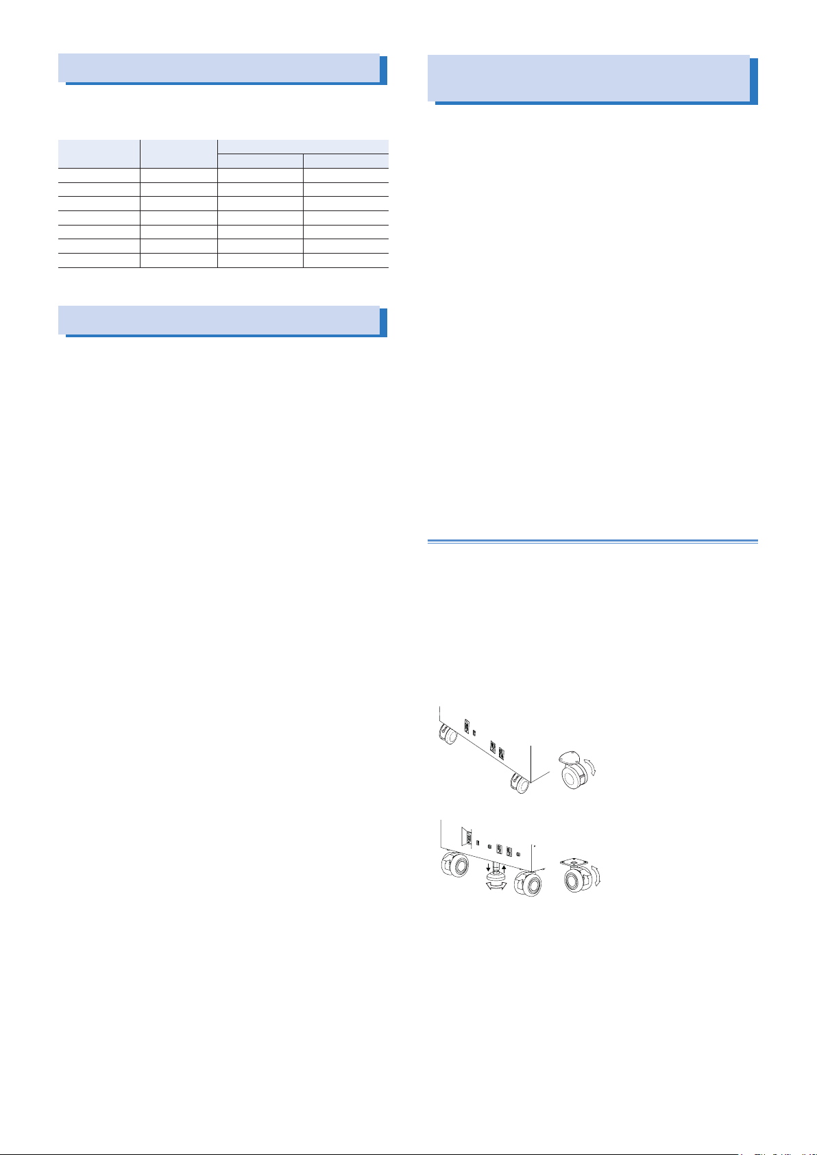
Raise the stopper.
●
Moving the product with the stopper lowered may cause injuries
due to the product falling over. (The PCR500LE, PCR1000LE,
and the PCR2000LE do not have a stopper.)
Unlock the casters (on all products excluding the PCR500LE).
●
Do not move the product by yourself (on all products excluding
●
the PCR500LE).
Be sure to have two or more people move the product. Exercise
special care when carrying the product over a slope or across
steps.
Hold the product from underneath.
Check the product’s weight before you transport it. The weight is
displayed in the bottom of the rear panel.
If you are using a forklift, be sure to slide the forks under the bot-
tom of the product, check that the product is stable, and then
raise the product.
If you are using a band or similar item to raise the product with a
crane, be sure to slide the band under the bottom of the product,
check that the product is stable, and then raise the product.
When you move the product, do not tip the product on its side or
●
turn it upside down.
Locking the casters and using the stopper
(on all products excluding the PCR500LE)
This product has casters on its bottom side, so it is easy to move
the product. To ensure that the product is not moved accidentally
while it is being operated, use the stopper to fix the product in
place, and lock the casters. The PCR1000LE and PCR2000LE do
not have stoppers.
Looking down at the stopper from above, turning the stopper to the
left (counterclockwise) raises the stopper, and turning the stopper
to the right (clockwise) lowers the stopper.
Lowering the lock lever on a caster locks the caster, and raising the
lock lever unlocks the caster.
Free
Lock
Free
Up
Down
6 PCR-LE series
Lock
Page 7
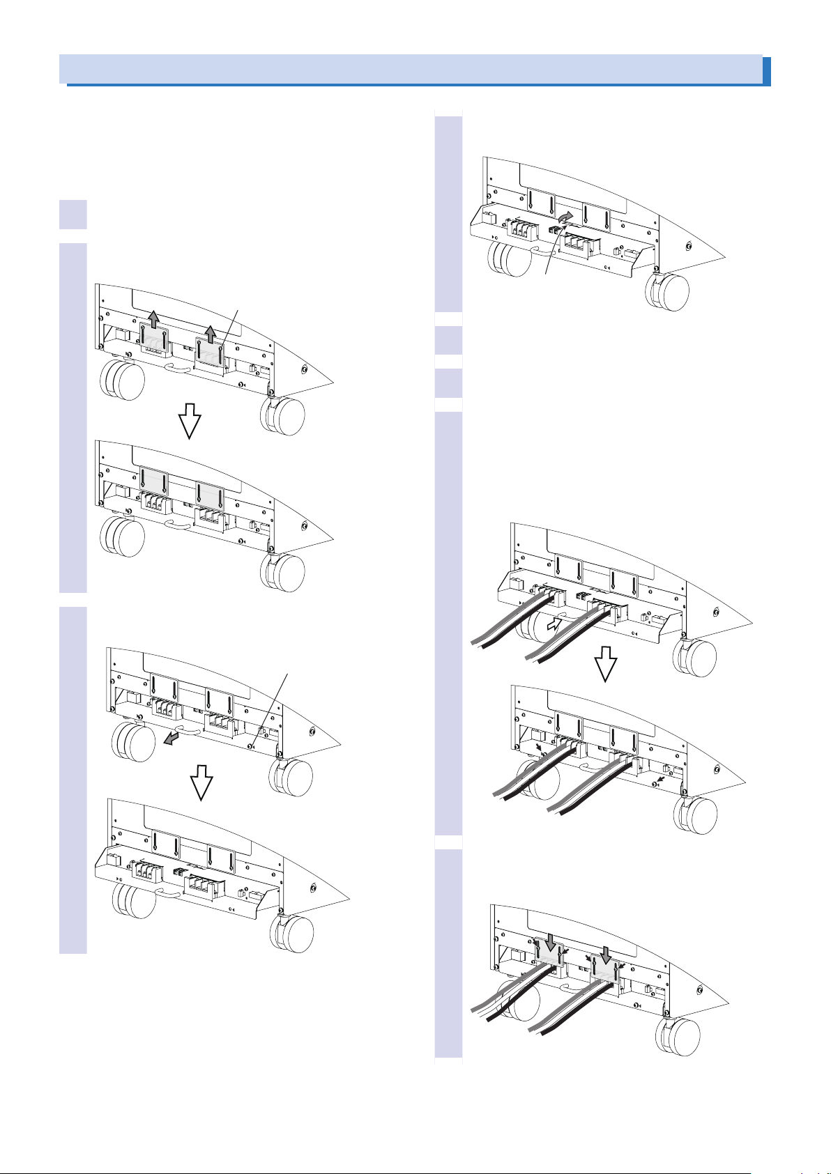
Handling the Terminal Block Tray (PCR1000LE - PCR9000LE)
The PCR-LE Series AC INPUT, OUTPUT terminal block, SENSING
terminal block, and J1 to J4 connectors are designed so that they
can only be wired after you first pull out the terminal block tray.
The terminal box covers ensure that you don’t touch the unwired
terminals. Use a Phillips-head screwdriver to insert and remove the
screws.
Check that the POWER switch is turned off.
1
Loosen the four terminal box cover screws, and
2
then slide the two covers up.
M3 x 4
Pull out the stopper to lock the terminal block tray
4
in place.
Stopper
Connect the wires and cables to the terminal block
5
and connectors as necessary.
Return the stopper to its previous position.
6
Return the terminal block tray to its previous posi-
7
tion, and then attach the two screws that you removed in step 3
If you do not insert the terminal block tray all the way into
its storage compartment, an electric current will not flow
through the PCR-LE even if the POWER switch is turned
on.
Remove the two terminal block tray screws, and
3
then pull the tray out.
M4 x 2
Slide the two terminal box covers down until they
8
are touching the wires, and then use the four screws
to x the terminal box covers in place.
PCR-LE series 7
Page 8
Connecting the PCR500LE Power Cord
This product conforms to IEC Overvoltage Category II (energyconsuming equipment that is supplied from a fixed installation).
WARNING
Risk of electric shock.
• This product conforms to IEC Safety Class I (equipment
that has a protective conductor terminal). Be sure to
earth ground the product to prevent electric shock.
• Connect the protective conductor terminal to earth
ground.Connect the protective conductor terminal to
earth ground.
• For the connected switchboard, select a breaker that
has a cut-off current that can handle the maximum input current of the product
CAUTION
If the voltage distortion of the AC power line is large, the
product may malfunction. The PCR-LE Series cannot be connected to a generator or a similar device.
Connecting the power cord (PCR1000LE - PCR 9000LE)
This product conforms to IEC Overvoltage Category II (energyconsuming equipment that is supplied from a fixed installation).
WARNING
Risk of electric shock.
• This product conforms to IEC Safety Class I (equipment
that has a protective conductor terminal). Be sure to
earth ground the product to prevent electric shock.
• Connect the protective conductor terminal to earth
ground.
• Turn off the circuit breaker of the switchboard before
you connect the power cord.
• Do not use the product with the terminal box covers
removed.
Risk of electric shock or re.
• For the connected switchboard, select a breaker that
has a cut-off current that can handle the maximum input current of the product
• Have a qualified engineer connect the power cord to
the switchboard.
- Note -
• Use the supplied power cord to connect to the AC line.
If the supplied power cord cannot be used because the rated
voltage or the plug shape is incompatible, have a qualied engineer replace it with an appropriate power cord that is 3 m or
less in length. If obtaining a power cord is difcult, contact your
Kikusui agent or distributor.
• The power cord with a plug can be used to disconnect the product from the AC power line in an emergency. Connect the plug
to an easily accessible power outlet so that the plug can be removed from the outlet at any time. Be sure to provide adequate
clearance around the power outlet.
• Do not use the supplied power cord with other instruments.
Check that the AC power line meets the nominal in-
1
put rating of the product.
The product can receive a nominal power supply voltage in
the range of 100 Vac to 120 Vac or 200 Vac to 240 Vac at a
frequency of 50 Hz or 60 Hz.
Check that the POWER switch is turned off.
2
Connect the power cord to the AC INPUT inlet on the
3
rear panel.
Insert the power cord plug into the outlet.
4
CAUTION
If the voltage distortion of the AC power line is large, the
product may malfunction. The PCR-LE Series cannot be connected to a generator or a similar device.
Inside the product, protective circuits such as input fuses are
connected to match the polarity of the input terminal. Be sure
to match the colors of the wires and the input terminals to
connect the wires correctly.
PCR500LE - PCR6000LE (Single-phase, 200 V input):
L, N, and (GND) - GND
PCR6000LE, PCR9000LE (Three-phase, 200 V input):
R, S, T, and
PCR6000LE, PCR9000LE (Three-phase, 400 V input):
R, S, T, N, and
- Note -
The POWER switch can be used to disconnect the product
from the AC power line in an emergency. Provide enough space
around the POWER switch to ensure that it can be turned off at
any time.
A power cord is not supplied with the PCR-LE Series.
Input power cords are available as options. When you are wiring
the switchboard, attach crimping terminals that match the screws
of the switchboard that has been connected by a qualified engineer.
If you will not use one of the optional input power cords, prepare a
power cord that meets the following specifications.
Single-phase,
200 V input
Three-phase,
200 V input
Three-phase,
400 V input
- GND)
- GND)
Cable Nominal cross-
PCR1000LE Heavy PVC jacketed
three-core cable
Alternatively, three
single-core cables
PCR2000LE Three single-core cables 8 mm
PCR3000LE 14 mm
PCR4000LE 22 mm
PCR6000LE 14 mm
PCR6000LE Four single-core cables 14 mm
PCR9000LE
PCR6000LE Five single-core cables 5.5mm
PCR9000LE
sectional area
5.5 mm
2
or more M4
2
or more M5
2
or more M8
2
or more M8
2
or more M8
2
or more M5
2
or more M5
Input
terminal
8 PCR-LE series
Page 9
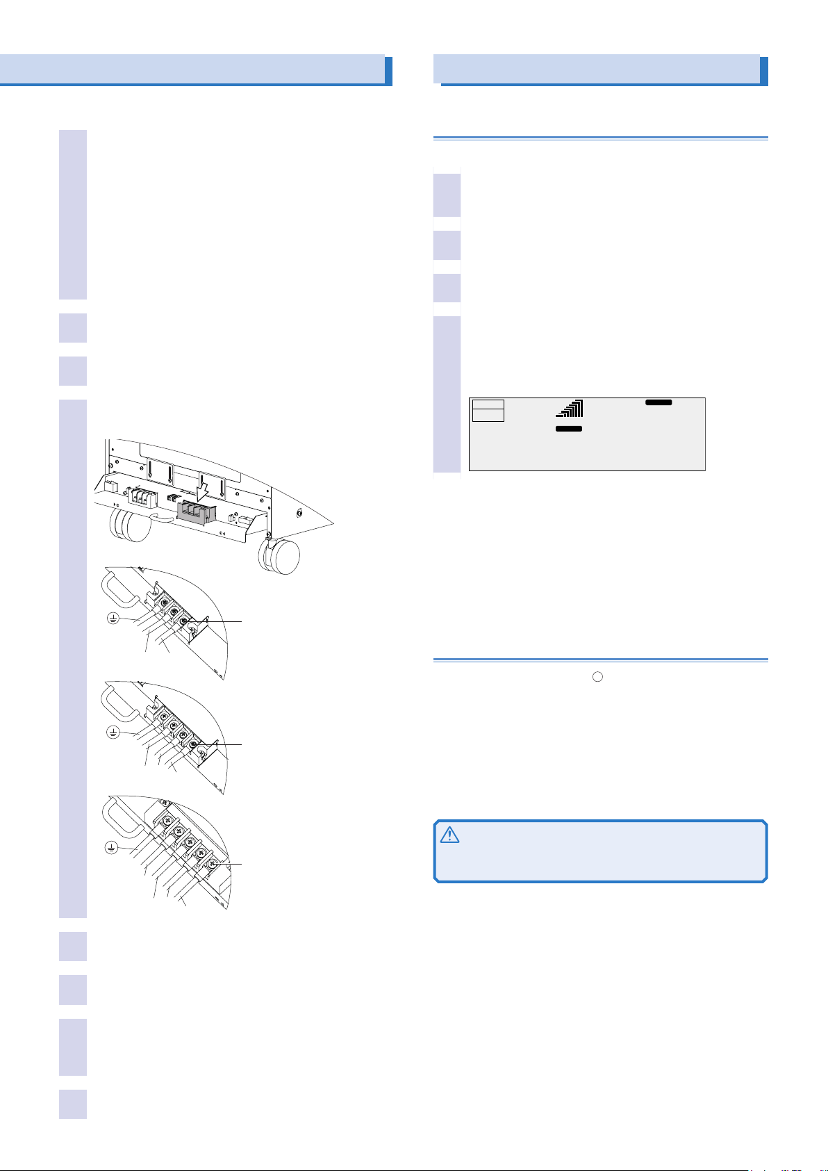
Pull out the terminal block tray, and then connect the power cord.
R
Single-phase, 200 V input
ACLOAD
Check that the AC power line meets the nominal in-
1
put rating of the product.
The product can receive a nominal power supply voltage:
PCR500LE - PCR4000LE (Single-phase, 200 V input)
100 Vac to 120 Vac or 200 Vac to 240 Vac
PCR6000LE (Single-phase, 200 V input):
200 Vac to 240 Vac
PCR6000LE, PCR9000LE (Three-phase 200 V input):
200 Vac to 240 Vac (Line Voltage)
PCR6000LE, PCR9000LE (Three-phase, 400 V input):
220 Vac to 240 Vac (Phase Voltage)
Frequency: 50 Hz or 60 Hz.
:
Turning the Power On
Turning the POWER switch on
Turn the power on without the load connected.
Check that nothing is connected to the OUTPUT ter-
1
minal block on the rear panel and the outlets on the
front panel.
Check that the power cord is connected correctly.
2
Check that the POWER SELECTOR switch is set to
3
“MASTER.”
Check that the POWER switch is turned off.
2
Pull out the terminal block tray.
3
Securely connect the power codes to corresponding
4
terminals of AC INPUT terminal block.
PCR1000LE - PCR6000LE
PCR1000LE : M4
PCR2000LE : M5
PCR3000LE - PCR6000LE: M8
N
L
PCR6000LE, PCR9000LE
Three-phase, 200 V input
M5
T
S
R
Flip the POWER switch to the ( | ) side to turn the
4
PCR-LE Series on.
The firmware version is displayed for a few seconds. If no
errors are detected, the home position (the basic screen)
appears.
Hz
0.0
RESP.M
V
OUTPUT
OFF
0.00
A
If the POWER switch is turned on for the first time after purchasing the PCR-LE Series, the PCR-LE Series starts up using factory
default settings. For all other cases, the PCR-LE starts up using the
settings that were in use the last time that the POWER switch was
turned off.
You can set the output on/off state at power on. For details, see
“User’s Manual -Basic-“ on the accompanying CD-ROM.
If “ALARM” or an error number is displayed, see “Alarms and Trouble” on the accompanying CD-ROM.
99.00
RANGE L
pk rms
Turning the POWER switch off
Flip the POWER switch to the ( ) side to turn the PCR-LE Series
off.
When the POWER switch is turned on, all items except for the following items take on the values that were in use the last time that
the POWER switch was turned off.
Waveform bank contents from number 24 to number 63
Output on/off state
If the POWER switch is turned off immediately after the settings
have been changed, the last settings may not be stored.
PCR6000LE, PCR9000LE
N
S
T
Turn off the switchboard’s breaker.
5
Securely connect the power codes to corresponding
6
terminals of switchboard's breaker.
Return the terminal block tray to its previous position.
7
If you do not insert the terminal block tray all the way into its
storage compartment, an electric current will not flow through
the PCR-LE Series even if the POWER switch is turned on.
Turn on the switchboard’s breaker.
8
PCR-LE series 9
Three-phase, 400 V input
M5
CAUTION
Risk of malfunction. After turning the POWER switch off, wait
at least 5 seconds before turning it back on.
Page 10
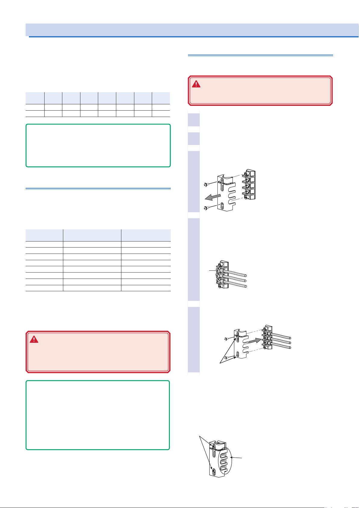
N
G
Use the upper holes to
attach the terminal cover.
cover in place. This keeps the OUTPUT
Connecting the Load
The maximum current that the PCR-LE Series can generate varies
depending on the model. It also varies depending on the PCR-LE
Series’ voltage mode, load type, and status. Ensure that the output
power capacity is sufficient for the load capacity. The maximum
output currents (in AC mode—AC rms, with an output voltage of 1
V to 100 V or 2 V to 200 V, and with a load power factor of 0.8 to 1)
for the different models are shown in the table.
PCR
PCR
PCR
PCR
PCR
PCR
500LE
1000LE
2000LE
3000LE
4000LE
L range 5 A 10 A 20 A 30 A 40 A 60 A 90 A
H range 2.5 A 5 A 10 A 15 A 20 A 30 A 45 A
- DESCRIPTION -
When the POWER switch is on, even if the output is off, a dangerous voltage exists between the output terminal (L or N) and
the chassis (G-ground). To eliminate the voltage between the
output terminal and the chassis, connect N and G of the OUTPUT
terminal block.
6000LE
PCR
9000LE
Connecting to the OUTPUT terminal block
Preparing wires
Use noncombustible wires that have diameters that correspond to
the output current to connect to the load.
Requirements of single-core wires that are used to connect to the load
Nominal crosssectional area[mm
0.9 18 (0.82) 17
1.25 16 (1.31) 19
2 14 (2.08) 27
3.5 12 (3.31) 37
5.5 10 (5.26) 49
8 8 (8.37) 61
14 6 (13.3) 88
22 4 (21.15) 115
* Excerpt from Japanese laws related to electrical equipment.
AWG (reference cross-
2
]
sectional area; mm
Allowable current
2
)
(A; at Ta = 30 °C, 86 °F)
*
Connecting cables (PCR500LE)
When shipped from the factory, the cover is attached using its upper holes so that the OUTPUT terminals are not exposed.
WARNING
Risk of electric shock. Do not use the terminal block
with the terminal cover removed.
Check that the POWER switch is turned off.
1
Check that the power cord is disconnected from the
2
outlet.
Remove the terminal cover that is attached to the
3
OUTPUT terminal block.
Securely connect the load cables to the OUTPUT ter-
4
minal block.
If the load has a ground (GND) terminal, be sure to connect
it to the G terminal of the PCR-LE Series OUTPUT terminal
block. Be sure to use a wire that is greater than or equal to
the diameter of the wires used to connect the load.
M4
L
N
G
The values vary depending on conditions such as the wire covering
(insulator), the wire material (allowable temperature), and whether
there are multiple cores in the cable. For cables other than those
specified in this table, consult with a qualified engineer.
WARNING
Risk of electric shock. Before you connect cables to
the OUTPUT terminal block, be sure to turn the POWER
switch off, and then remove the power plug from the
outlet or turn off the switchboard.
- Note -
The L and N terminals of the OUTPUT terminal block are isolated
from the input power supply. The polarity does not constitute a
problem in terms of safety. The polarity matters in synchro mode
(in which the product is synchronized with the input power supply)
and DC mode, so check the polarity of the load before you connect
it to the product. You can use either L or N to ground the product.
In DC mode and AC+DC mode, N is the reference. When N has
a positive polarity, L is positive electric potential. When N has a
negative polarity, L is negative electric potential.
Screw diameter of OUTPUT terminals
PCR500LE, PCR1000LE, and PCR2000LE: M4
PCR3000LE and PCR4000LE: M5
PCR6000LE and PCR9000LE: M8
10 PCR-LE series
Use the lower holes to attach the terminal cover that
5
you removed in step 3 .
L
Use the lower holes.
Twist the load wires (L and N), and connect between the output terminal and load with the shortest wires possible. If you cannot twist
the wires, we recommend that you run the wires alongside each
other and tie them together at several points with cable ties.
When you are not using the OUTPUT terminal block, attach the terminal cover.
Use the upper holes to fix the terminal
terminals from being exposed.
Page 11
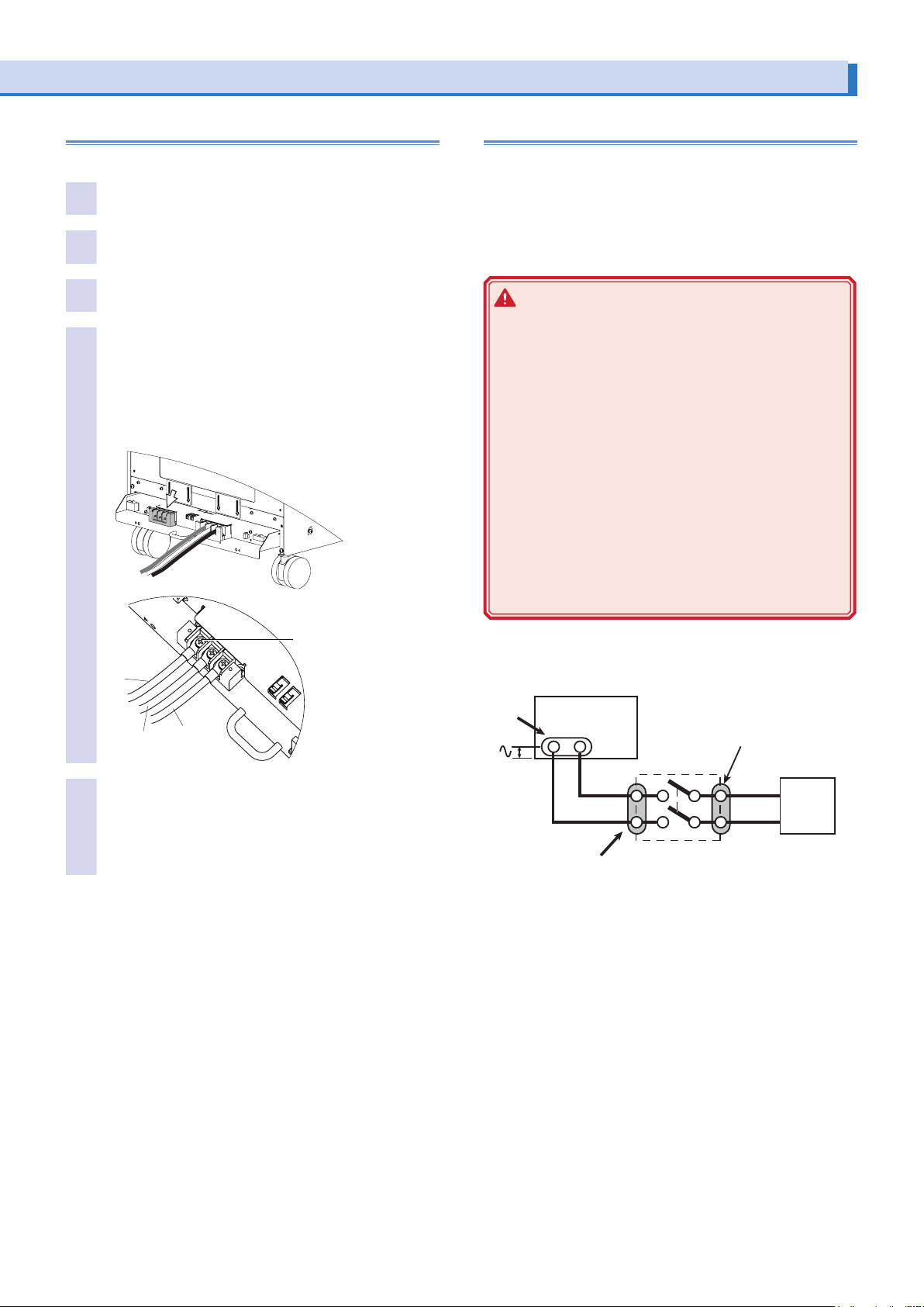
Connecting cables(PCR1000LE - PCR9000LE)
Risk of electric shock. Do not touch the terminals.
Before you connect the cables, be sure to turn the POWER switch
OUTPUT
terminal
block
When the load is located at a remote location
Pull out the terminal block tray, and then connect the load cables.
Check that the POWER switch is turned off.
1
Check that the breaker of the switchboard is off.
2
Pull out the terminal block tray.
3
Securely connect the load cables to the OUTPUT ter-
4
minal block.
If the load has a ground (GND) terminal, be sure to connect
it to the G terminal of the PCR-LE Series OUTPUT terminal
block. Be sure to use a wire whose diameter is greater than
or equal to the diameter of the wires used to connect the
load.
PCR1000LE, PCR2000LE : M4
PCR3000LE, PCR4000LE : M5
PCR6000LE, PCR9000LE : M8
G
L
N
Return the terminal block tray to its previous posi-
5
tion.
If you do not insert the terminal block tray all the way into
its storage compartment, an electric current will not flow
through the PCR-LE Series even if the POWER switch is
turned on.
If the load is located at a remote location, the PCR-LE may need be
controlled remotely.
Remote control can be used to turn the output off, but it cannot be
used to turn the POWER switch off. If you want to connect the PCRLE Series to a load that is located at a remote location, install a
switch between the OUTPUT terminal block and the load to prevent
electric shock. Then, turn that switch off.
WARNING
Risk of electric shock.
• Before you install the switch between the OUTPUT terminal block and the load, be sure to turn the POWER
switch off and remove the power plug from its outlet
or turn off the breaker of the switchboard.
• The current rating of the switch must be greater than
or equal to the maximum current of the PCR-LE Series.
• For the switch circuit, use a two-pole type switch that
can cut off the L and N wires simultaneously.
• Be sure to turn the switch off before connecting the
load to the terminal at the load end of the switch.
• Do not touch the switch terminals when the POWER
switch is on. Do not touch the switch terminals when
the POWER switch is on. Before you connect cables
to the OUTPUT terminal block, be sure to turn the
POWER switch off, and then turn off the switchboard.
off and remove the power plug from its outlet or turn off the breaker
of the switchboard.
PCR-LE
OUTPUT
N L
Terminals on the OUTPUT terminal block side
Terminals on the load side
Turn the switch off, and then
connect the load.
Switch
L
N
LOAD
Twist the load wires (L and N), and connect between the output terminal and load with the shortest wires possible. If you cannot twist
the wires, we recommend that you run the wires alongside each
other and tie them together at several points with cable ties.
PCR-LE series 11
Page 12

Connecting the Load (Cont.)
Connecting to the front-panel outlets
The PCR-LE Series can generate power from the OUTPUT terminal block on the rear panel and the outlets on the front panel. The
specifications of the front-panel outlets are not regulated. Their performance may decrease.
CAUTION
The maximum rated voltage of the front-panel outlets is 250
Vac.
Max. output voltage: 250 Vac(rms)
Maximum output current:
10 Aac (rms) per outlet (on models other than the PCR500LE)
5 Aac (rms) total for the two outlets on the PCR500LE
10 Aac (rms) total for the two outlets on the PCR1000LE
Do not disconnect the load when the maximum rated voltage
of the outlets has been exceeded or in DC mode. Doing so
may cause the product to malfunction.
On the PCR-LE Series (excluding the PCR500LE and PCR1000LE),
if an overcurrent is detected, the breaker trips, and the output is cut
off.
The outlets are designed for power plugs like those shown below.
NEMA5-15
NEMA1-15
The output current may be lower than the maximum output current
due to the output voltage, the output frequency, and the load power
factor.
For example, on the PCR1000LE, if the output voltage is 115 V, the
load power factor is 0.7, and the output frequency is 50 Hz, the total maximum output current for the two outlets is 7.61 A. If an output
current of 5 A is drawn from one of the outlets, the maximum output
current that can be drawn from the other outlet is 2.61 A.
Turn the POWER switch off.
1
Connect the power cord of the load device to a front-
2
panel outlet.
12 PCR-LE series
Page 13
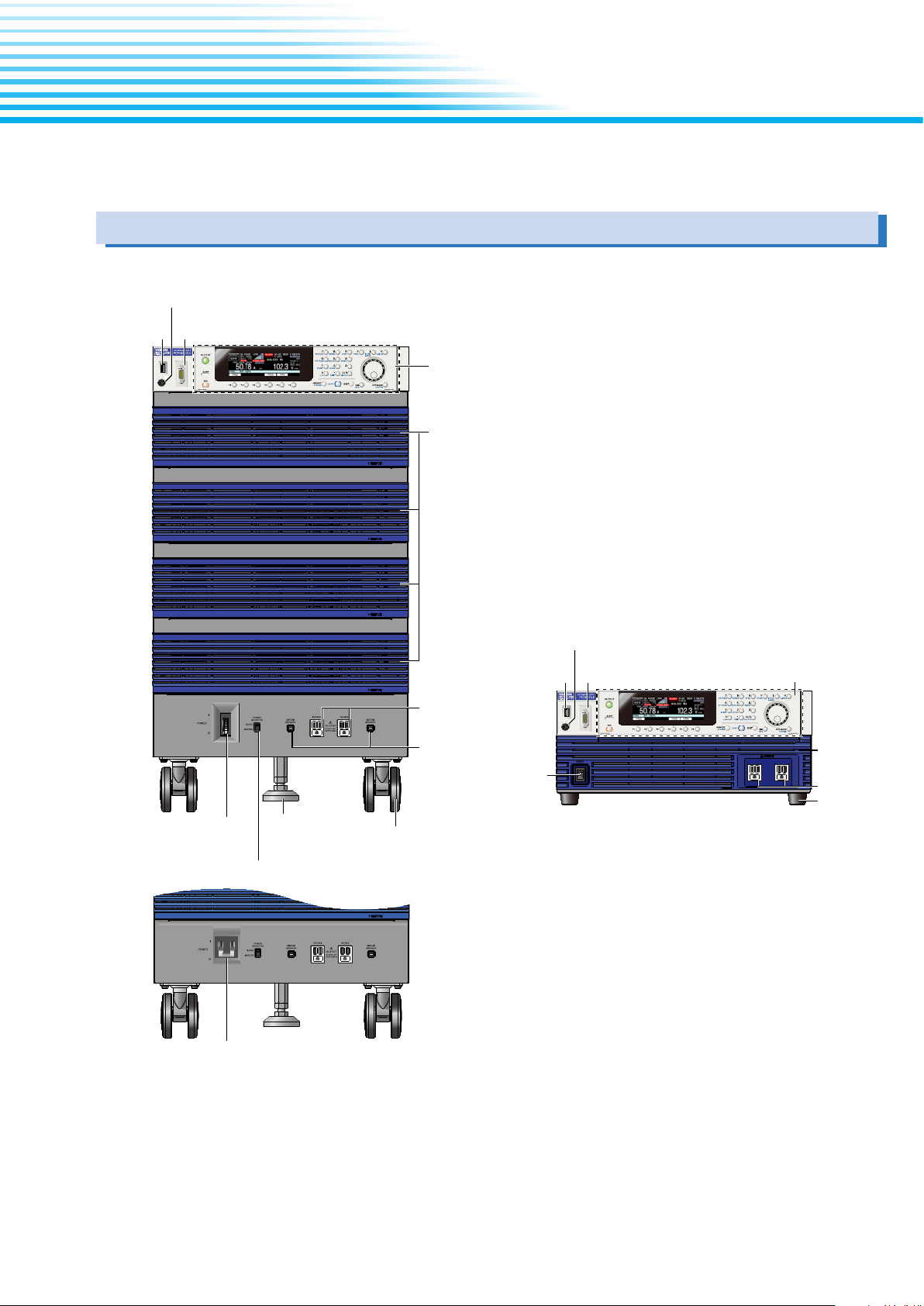
This chapter explains the basic operating procedures of the PCR-LE Series.
POWER switch
of the PCR-LE
connector
PCR-LE (excluding the PCR500LE; example of the PCR4000LE)
Front Panel
REMOTE connector (not used)
RS232C
USB
connector
Control Panel
Power units and air inlet of the PCR-LE Series
- Basic -
POWER switch
Turns the power
on and off.
POWER SELECTOR switch
Stopper
OUTPUT
CIRCUIT BREAKER
The outlet breaker
recovery buttons
Casters
PCR9000LE 400 V input
REMOTE connector
connector
POWER switch
Turns the power
on and off
USB
(not used)
RS232C
connector
PCR500LE
Control Panel
Power units
and air inlet
Series
OUTPUT
Feet
PCR-LE series 13
Page 14
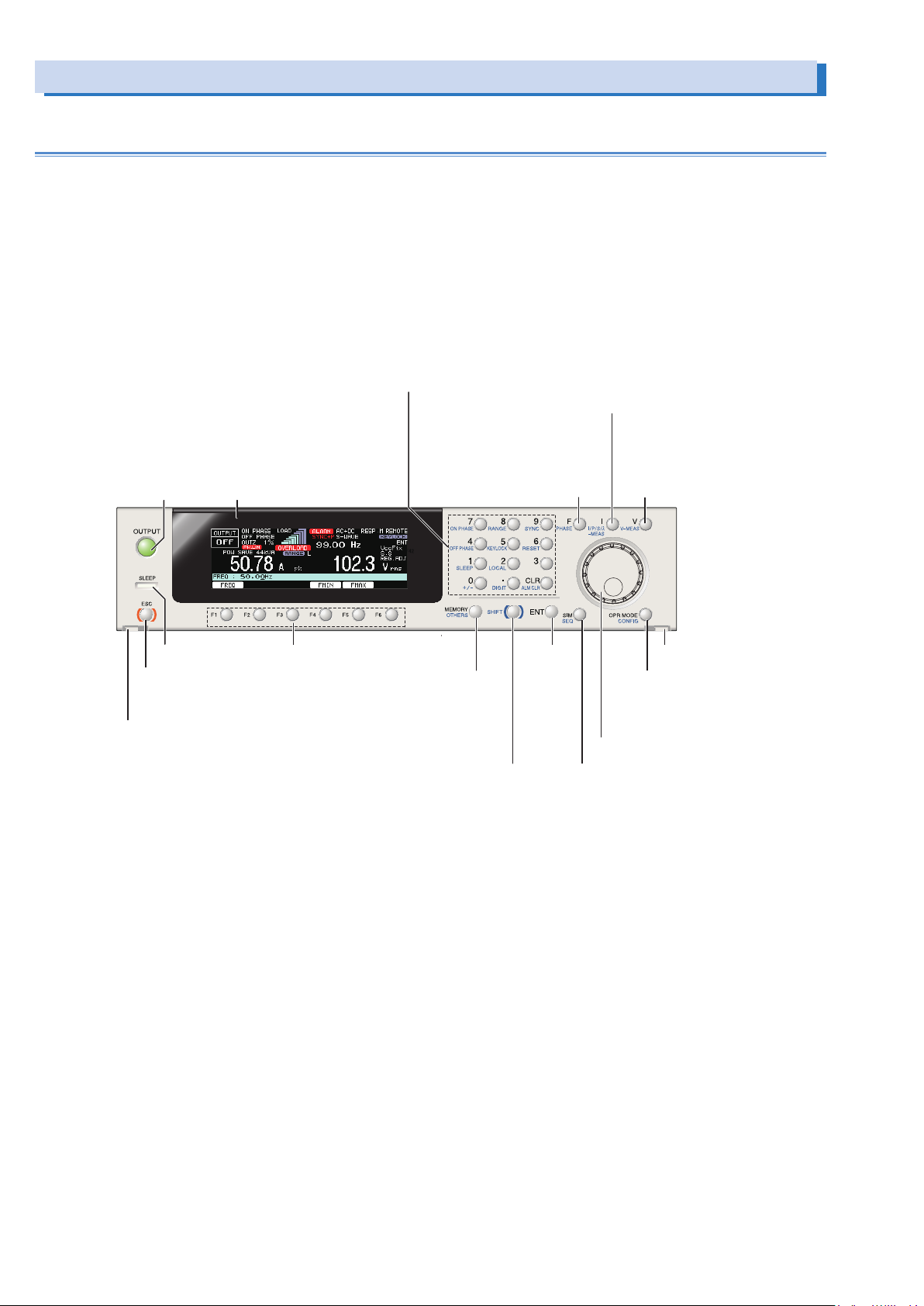
Front Panel (Cont.)
Turn output on and off
Configure sequence operations
Numeric keypad/ Setting key
Switch the current/power measurement mode
Control Panel
Numeric keypad Enter numeric values directly
CLR key Clear the numeric keypad input.
ON PHASE key Set the output on phase
RANGE key Switch between output voltage ranges
SYNC key Enable the synchronization function
OFF PHASE key Set the output off phase
KEYLOCK key Lock and unlock the keys
RESET key Reset the product
SLEEP key Configure the sleep mode settings
LOCAL key Switch between remote mode and local mode
+/- key Switch the polarity (+ or -) of the voltage in DC mode
DIGIT key The cursor moves to the left (the higher-order
digit) each time this key is pressed
ALM CLR key Clear alarms.
I key
Configure the current settings
I/P/S/λ-MEAS key
OUTPUT key
Display
SLEEP LED Function keys
ESC key
return to the previous level’ s
operation and to cancel operations
Detachment button
Detach the control panel (There are two)
Set the frequency
Switch between different displays
during multiphase operation (optional)
ENT key
Save settings to and load
Configure advanced operation settings
Enable the functions that are indicated in blue
characters in the bottom row to the left of each key
MEMORY key
settings from memory
OTHERS key
SHIFT key
apply
settings
F key
PHASE key
V key
Configure the voltage settings
V-MEAS key
Switch the voltage
measurement mode
Detachment button
OPR MODE key
Configure the operation
environment settings
CONFIG key
Specify the configuration settings
Rotary knob
SIM key
Configure power line abnormality simulations
SEQ key
14 PCR-LE series
Page 15
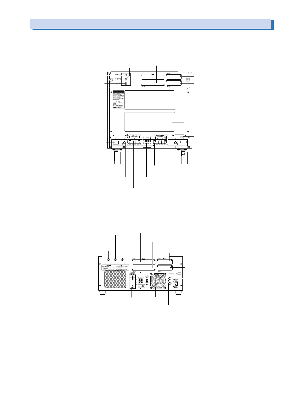
Rear Panel
Connecting a BNC cable (trigger output) to
Expansion slot for a communication
The output terminal block with cover
PCR-LE (excluding the PCR500LE; example of the PCR2000LE)
SEQ TRIG IN connector
Expansion slot for a communication
PCR500LE
POWER SELECTOR switch
SEQ STAT OUT connector
SEQ TRIG OUT connector
SEQ TRIG IN connector
Connecting a BNC cable (trigger input) to
J4 connector
Connecting options
SLOT1
Expansion slot for a multiphase operation (optional)
Connecting a BNC cable
(status output) to
J2 connector
Connecting options
OUTPUT terminal block
SLOT3
Expansion slot for an analog signal interface (optional)
SLOT2
Expansion slot for a master-slave
parallel operation (optional)
SLOT4
interface (optional)
Vent hole
Serial number
J3 connector
Connecting options
J1 connector
Connecting
options
AC INPUT
The AC INPUT terminal block with cover
SENSING terminal block
Connect the sensing cables to
Connecting a BNC cable (trigger input) to
SEQ STAT OUT connector
Connecting a BNC cable (status output) to
Connecting a BNC cable (trigger output) to
SEQ TRIG OUT connector
OUTPUT terminal block
The output terminal block with cover
SENSING terminal block
Connect the sensing cables to
SLOT1
Expansion slot for a multiphase operation (optional)
SLOT3
Expansion slot for an analog signal interface (optional)
SLOT2
Expansion slots
SLOT4
interface (optional)
Serial number
J1 connector
Connecting options
Vent hole
AC INPUT
J2 connector
Connecting options
PCR-LE series 15
Page 16

Panel Operation Basics
This section explains the status indicators of the product and the basics of operating the product from the front panel.
Control panel
You can pull out the control panel and tilt it to one of the two available settings.
If you use the optional EC05-PCR extension cable, you can use the control panel while it is detached from the PCR-LE Series.
Detaching the control panel
Hold down the two control panel detachment buttons, and pull
the control panel toward you.
The control panel will come free of the PCR-LE Series. The control panel and the PCR-LE Series are connected by a cable. Do
not pull hard on the control panel.
Upper groove
Lower groove
While pressing in the two locations
(indicated by this arrow in the figure),
detach the panel by pulling it toward you.
Attaching the control panel
The control panel detachment buttons are not used when you
attach the control panel to the PCR-LE Series. Simply press on
the control panel until you hear a click.
•
Factory default
Align the upper groove and the lower groove on the control
panel with the upper pin and lower pin on the PCR-LE Series,
respectively, and then push the control panel back into the
PCR-LE Series.
Upper pin
Lower pin
•
Tilt slightly
Align the upper groove on the control panel with the upper
pin on the PCR-LE Series, and then push the control panel
back into the PCR-LE Series until the protruding part of the
control panel lines up with the slanted surface of the PCR-LE
Series.
Upper pin
Upper groove
Protruding part
of the panel
Slanted
surface
•
Make it easily viewable from above.
Align the lower groove on the control panel with the upper pin
on the PCR-LE Series, and then push the control panel back
into the PCR-LE Series until the protruding part of the control
panel sits on the slanted surface of the PCR-LE Series.
Lower
groove
Upper pin
Protruding part
of the panel
Slanted surface
16 PCR-LE series
Page 17
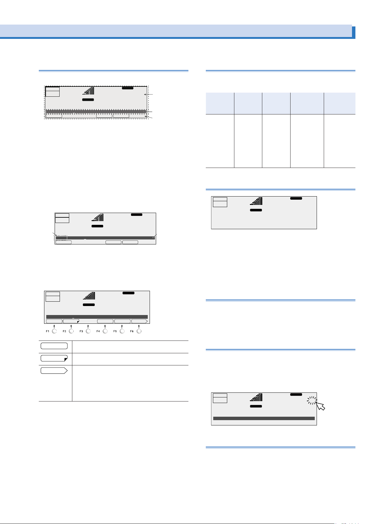
Parts of the screen
name area
Status,
FMINFMAXFREQ
ACLOAD
Entry area
Title
RESP.M
ACLOAD
ACLOAD
Blinking
Explanation of function keys in this manual
The screen consists of the following three parts.
RESP.M
L
99.00
ACLOAD
Hz
28.1
FMINFMAXFREQ
measured-value,
and setting
display area
V
Entry area
Function key
OUTPUT
OFF
6.87
Freq 50.00Hz
Status, measured-value, and setting display area
RANGE
rms rms
A
This displays the product’s present status, measured values,
and settings.
Entry area
Settings and system settings are entered in this area.
This area displays a title and its corresponding setting.
If an alarm or trouble occurs, the alarm code or the trouble
code is displayed here.
OUTPUT
OFF
6.87
Freq
Function key name area
50.00Hz
A
99.00
RANGE
L
rms rms
Hz
28.1
V
The present functions are displayed above the function keys (F1
to F6). The displayed contents vary depending on the selected
output voltage mode.
OUTPUT
OFF
6.87
ILimit 5.50A
58.00
RANGE
L
pk rms
A
RESP.M
Hz
28.1
-IPKLIM+IPKLIM 1/2TRIPILIMIT
V
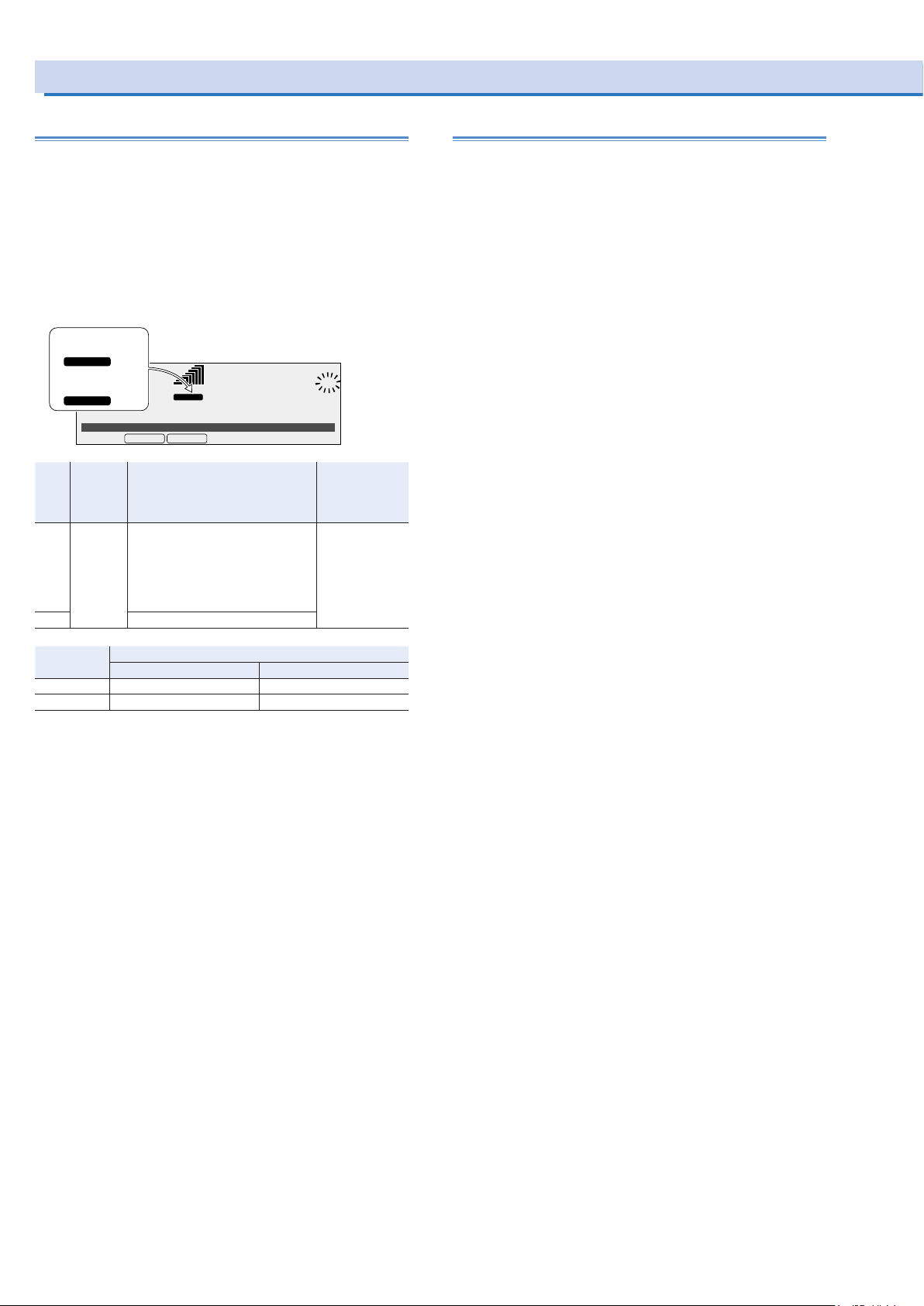
The function keys in this manual are explained in a tabular form
as shown below.
Item Title Description
The item
name that is
displayed in
the function
key name
area
The title that
is displayed
in the entry
area
An explanation of the
function key
Conditions in
which the function key cannot
be used
When the PCRLE Series is being used under
the conditions
listed here, the
contents that
are listed for the
item cannot be
selected.
Valid modes
This indicates
the PCR-LE
Series modes
during which the
function key is
valid. If the valid
modes are not
listed, the function key is valid
in all modes.
Home position
Hz
0.1
RESP.M
V
OUTPUT
OFF
0.05
A
99.00
RANGE L
pk rms
The screen that is displayed that you turn the POWER switch
on is called the “home position” (the basic screen). The home
position is the top level in the menu hierarchy. All functions are
arranged within the menu hierarchy.
No matter which function you are using, if you repeatedly press
ESC, you will move back up through the menu hierarchy towards the home position.
Canceling settings
Press ESC to return to the previous screen.
If you want to cancel settings that you have made, repeatedly
press ESC until you return to the home position. If you press
ESC at the home position, a buzzer will sound.
This indicates that you can set the displayed item by
pressing the function key.
This indicates that there is a sub level in the function
menu hierarchy.
This indicates that there is another page in the function
menu.
The function key name indicates the following: “present page/total number of pages.” The PCR-LE Series
switches between the pages each time that you press
this function key.
ENT wait
The PCR-LE Series has an “ENT wait” state during which you
can confirm the operation results (the ENT indicator blinks). The
ENT wait state continues until the ENT key is pressed. Press
ENT to apply the settings.
Press ESC to cancel the settings.
RESP.M
L
58.00
AC
Hz
28.1
ENT
V
OUTPUT
OFF
ACVolt
6.87
27.1
LOAD
RANGE
rms rms
A
Restoring to factory default settings
You can return all the settings to their factory defaults or return
just a portion of the settings to their factory defaults. For details,
see Appendex.A Restoring to factory default settings.
PCR-LE series 17
Page 18
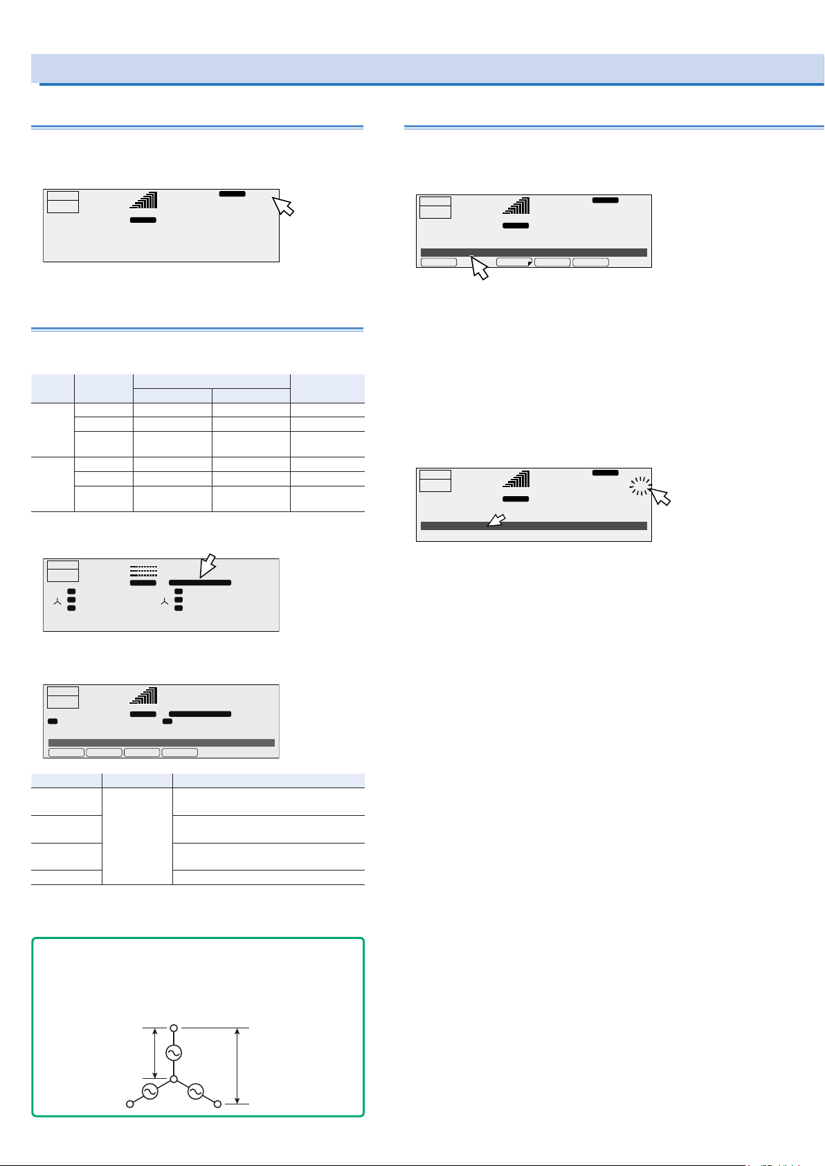
Panel Operation Basics (Cont.)
ACLOAD
W ALLVU
In three-phase AC output, when the phase difference between U, V, and W
√
3
ACLOAD
AC
LOAD
Blinking
Switching from remote mode to local mode
When the PCR-LE Series is in remote mode, “RMT” is displayed
on the screen. To switch the PCR-LE Series to local mode from
the panel, press LOCAL (SHIFT+2).
RESP.M
OUTPUT
OFF
50.78
99.00
RANGE
L
pk rms
A
Hz
102.3
RMT
V
Displaying single-phase, three-wire output
and three-phase output (optional)
The output is displayed on the U-phase unit. With an unbalanced configuration, the unbalance icon is displayed.
Output Voltage of
Singlephase
threewire
Threephase
each phase
Same Other than 180° -- UNBAL.PHAS
Different 180° -- UNBAL.VOLT
Different Other than 180° -- UNBAL.PHAS,
Same Other than 120° Other than 240° UNBAL.PHAS
Different 120° 240° UNBAL.VOLT
Different Other than 120° Other than 240° UNBAL.PHAS,
*1. If either the “U and V” or “U and W” condition applies, the configuration is
considered unbalanced.
Phase differences Display
U and V U and W
VOLT
VOLT
*1
Specifying values
To specify values, use the numeric keypad or the rotary knob.
When the cursor is displayed in the entry area, you can use the
numeric keypad or the rotary knob to specify a value.
OUTPUT
OFF
6.87
ACVolt 0.0V
Numeric keypad operations
A
58.00
RANGE
L
rms rms
If you use the numeric keypad to enter a value, the value that
you entered is displayed in the entry area.
To enter a negative value, first press +/- (SHIFT+0).
Press CLR to clear any settings that you have made before
pressing ENT.
Press ENT to apply the values that you have specified. If you
press ESC before you press ENT, any settings that you have
*1
made will be canceled.
OUTPUT
OFF
ACVolt
6.87
27.1
RANGE
A
58.00
L
rms rms
RESP.M
Hz
28.1
VMINVMAXACVOLT PROTECT
RESP.M
Hz
28.1
V
ENT
V
OUTPUT
OFF
U
VW
LOAD
U
V
W
RANGE
0.01
A
1.11
A
rms rms
2.22
A
99.00
UNBAL.PHAS, VOLT
L
U
U
V
VW
W
AC
Hz
0.2
V
1.2
V
2.3
V
Only one phase can be displayed. Select the phase that you
want to display using the PHASE (SHIFT+F) key.
OUTPUT
OFF
50.78
DispPhase ALL
Item Title Description
U DispPhase The U phase is displayed. The line volt-
V The V phase is displayed. The line volt-
*1
W
ALL All phases are displayed.
*1. Three-phase output only
RANGE
pk rms
A
AC+DCLOAD
99.00
Hz
UNBAL.PHAS, VOLT
L
UU
102.3
age is the voltage between U and V.
age is the voltage between V and W.
The W phase is displayed. The line voltage is the voltage between W and U.
V
You can display the line voltage. -> p28
- Note -
Phase voltage and line voltage
is 120° and the output voltages are equal,
Line Voltage = √3 × Phase voltage Phase voltage = Line voltage /
Phase
voltage
PCR-LE
PCR-LE
PCR-LE
Line voltage
18 PCR-LE series
Page 19
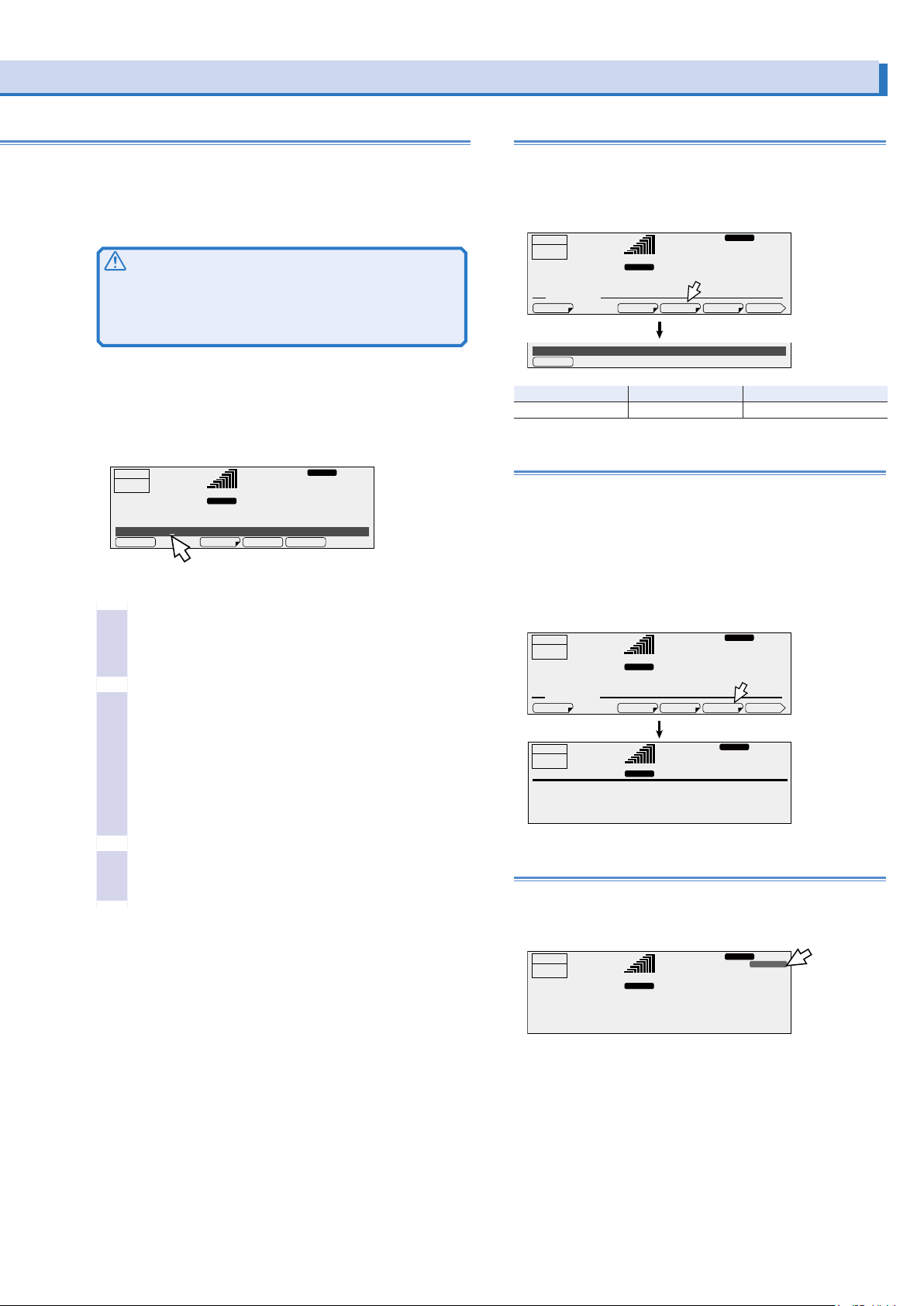
Adjusting the screen brightness
INTEN
ACLOAD
ACLOAD
the cursor moves.
Rotary knob operations
Turn the rotary knob to the right to increase the displayed value.
Turn the rotary knob to the left to decrease the displayed value.
You do not need to press ENT.
CAUTION
A voltage or frequency that is greater than is necessary may
cause damage to the load or put the operator in danger. Be
sure to set the voltage and frequency limits. For details, see
“Setting Limits”.
Digit function
The digit function enables you to use the rotary knob to change
only the specified digit and the higher digits when you are setting the voltage or frequency. This function is useful when you
are changing the voltage or frequency in steps.
ACLOAD
OUTPUT
OFF
6.87
ACVolt 0.0V
Each time that you press DIGIT (SHIFT+.),
Check that the PCR-LE Series is in a state in
3
which you can specify a value.
The digit function is valid when the cursor is displayed at a
value in the entry area.
Press DIGIT (SHIFT+.) until the cursor is displayed
4
at the digit that you want to change.
Only the digit that is indicated by the cursor and the higher
digits will be changed (except when the value that you
are changing reaches the maximum or minimum settable
value).
Each time that you press DIGIT (SHIFT+.), the cursor moves
to the left. If the cursor is at the highest digit and you press
DIGIT (SHIFT+.), the cursor will move to the lowest digit.
A
58.00
RANGE
L
rms rms
RESP.M
Hz
28.1
VMINVMAXACVOLT PROTECT
V
You can set the screen brightness to one of three levels (1 to 3).
The larger the number, the brighter the screen.
Press CONFIG (SHIFT+OPR MODE) and then DISPLAY (F4) to
set the screen brightness.
OUTPUT
OFF
6.87
CONFIG. MEMU
Inten 3
Item Title Description
INTEN Inten Sets the screen brightness
A
99.00
RANGE
L
rms rms
RESP.M
Hz
28.1
MODEL IDDISPLAYSIG.I/OCOM-I/F
V
1/2
Viewing the rmware version
To view the PCR-LE’s firmware version, press CONFIG
(SHIFT+OPR MODE) and then MODEL ID (F5).
During single-phase, three-wire output and three-phase output
(optional), you can view the version of each phase unit or system by pressing function key.
During master-slave parallel operation(optional), you can view
the version of each phase unit or system by pressing function
key.
Hz
28.1
MODEL IDDISPLAYSIG.I/OCOM-I/F 1/2
ACLOAD
0.9
V rms
RESP.M
RESP.M
V
OUTPUT
OFF
6.87
CONFIG. MEMU
OUTPUT
OFF
0.1
PCR 4000LE
CPU Version : 1.00
Serial NO : xxxxxxxx
A rms
50.00
RANGE
L
rms rms
A
50.00Hz
RANGE
L
Use the rotary knob to set the value.
5
The digit function is not valid if you are using the numeric
keypad to enter the value.
Locking panel operations (key lock)
You can lock the PCR-LE’s keys to prevent mistaken operations
such as changes to the settings and overwriting of memory entries.
RESP.M
L
99.00
ACLOAD
Hz
102.3
KEYLOCK
V
OUTPUT
OFF
50.78
•
Locking keys
RANGE
pk rms
A
Press KEYLOCK (SHIFT+5) to lock the panel keys except the
OUTPUT key and the KEYLOCK (SHIFT+F5) key. When the
keys are locked, “KEYLOCK” is displayed on the screen.
•
Unlocking keys
While the keys are locked, press KEYLOCK (SHIFT+5) again
to unlock the keys.
PCR-LE series 19
Page 20

Selecting the Output Mode
U phase
V phase
U phase
V phase
ON OFF
If the 2P05-PCR-LE single-phase, three-wire output option is
installed, select whether to use single-phase, three-wire output
or two-phase output .
The output cannot be turned on for a few seconds after the output method is switched (Busy state).
The example below shows the output of a user-defined waveform whose U-V phase difference is 180° (factory default setting). The phase difference is 180° in both cases, but the output
waveforms are different.
•
Single-phase, three-wire output (2P Mode OFF) waveform
The phase setting is 180°, but the V phase is not 180° out of
phase with the U phase. The V phase is an inverted waveform of the U phase.
To use single-phase, three-wire output, set 2P Mode to OFF.
•
Two-phase output (2P Mode ON) waveform
The V phase is 180° behind the U phase.
Setting the output mode
Press OPR MODE and then 2P (F3) to select the output
mode.
RESP.M
OUTPUT
OFF
6.87
OPERATION MODE. MEMU
2P Mode ON
Item Title Description Condition in which the func-
ON 2P Mode Two-phase output Output on
OFF Single-phase, three-
RANGE L
2P
rms
A
wire output
ACLOAD
Displayed when you
99.00
select “ON”
Hz
28.1
POW SAVACDC 2P
DC mode
Output on
rms
V
tion key cannot be used
180° phase
difference
If you want to use two-phase such as in a V wiring connection, set 2P Mode to ON.
To set the phase difference between U and V, press V, 1/2 (F6),
and then UV PHASE (F4). -> p24
20 PCR-LE series
Page 21
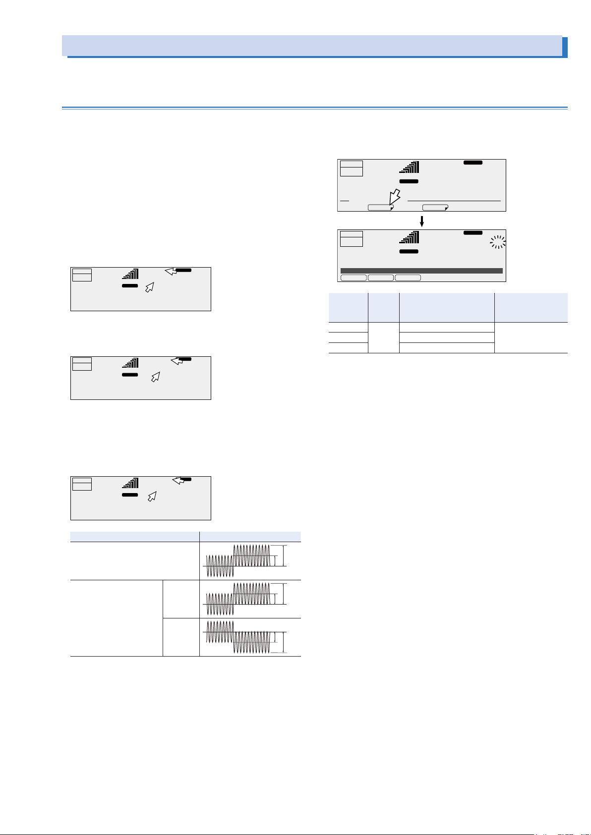
Setting the Output Voltage
DCLOAD
ACLOAD
Blinking
To set the output voltage, set the output voltage mode, the output voltage range, and the output voltage value.
Setting the output voltage mode
The PCR-LE Series has the following output voltage modes:
AC, DC, and AC+DC.
You can switch between modes when the output is off.
The AC voltage setting is shared between AC and AC+DC
modes.
The DC voltage setting is shared between DC and AC+DC
modes.
During three-phase output (optional), only AC mode and
AC+DC mode are available.
•
AC mode
AC output is generated. “AC” and the frequency are displayed.
RESP.M
OUTPUT
OFF
•
DC mode
50.78
RANGE
A
ACLOAD
99.00
L
pk rms
Hz
102.3
V
DC output is generated. “DC” is displayed.
OUTPUT
OFF
50.78
RANGE
L
pk rms
A
RESP.M
dc
102.3
V
Output voltage mode setup procedure
Press OPR MODE and then ACDC (F2) to select the output
voltage mode. Then, press ENT to confirm the selection.
OUTPUT
OFF
6.87
OPERATION MODE. MEMU
OUTPUT
OFF
6.87
VMode
Item Title Description Condition in which
AC VMode AC mode is selected. Output on
DC DC mode is selected.
AC+DC AC+DC mode is selected.
*1. If the output voltage mode is changed from AC or DC to AC+DC and the peak
voltage of the resultant AC+DC waveform falls outside the -215.5 V to 215.5 V
range (L range) or -431 V to 431 V range (H range), the DC voltage setting is
forced to 0 V.
A
A
AC
AC+DCDCAC
99.00
RANGE L
rms
POW SAVACDC
99.00
RANGE L
rms rms
RESP.M
Hz
28.1
RESP.M
ACLOAD
Hz
28.1
rms
V
ENT
V
the function key can-
not be used
*1
•
AC+DC modeAC+DC mode
Voltage waveforms in which AC has been superimposed on
DC and voltage waveforms in which DC has been superimposed on AC are generated. “AC+DC” and the frequency of
the AC component are displayed.
OUTPUT
OFF
50.78
Single-phase output
Two-phase output (2P MODE ON)
Three-phase output
Three-phase output (2P
MODE OFF)
*1. The V phase is automatically set to the same amplitude as the U phase but
with opposite polarity.
LOAD
99.00
RANGE
L
pk rms
A
Output mode Example) Output voltage
RESP.M
AC+DC
Hz
102.3
U-phase
V-phase
V
DC
DC
*1
DC
AC
AC
AC
PCR-LE series 21
Page 22
Setting the Output Voltage (Cont.)
Blinking
Setting the output voltage range
The PCR-LE Series has the following output voltage ranges: L
and H.
The maximum output current varies depending on the output
voltage range. The maximum output current of the H range is
half of the maximum output current of the L range.
You can switch between settings when the output is off.
Output voltage range setup procedure
Press RANGE (SHIFT+8) to select the output voltage range.
When you select
the L range,
RANGE L
OUTPUT
When you select
OFF
the H range,
RANGE H
6.87
VRange
Item Title Description Condition in
L VRange The L range is selected.
H The H range is selected.
Output voltage setting range
AC voltage DC voltage
L range 0 V to 152.5 V -215.5 V to +215.5 V
H range 0 V to 305.0 V -431.0 V to +431.0 V
The output cannot be turned on for approximately 0.6 ms after
the range is switched (Busy state).
LOAD
RANGE
A
L
HL
If you specify a value that is greater
than 152.5 V with the H range
selected and then switch to the L
range, the output voltage will be
set to 0 V.
58.00
L
28.1
rms rms
Hz
V
ENT
which the function key cannot
be used
Output on
Setting the output voltage
You can set the output voltage while output is on or off. The
measured value is always displayed.
Set the voltage limit to prevent the PCR-LE Series from generating a voltage that is greater than is necessary.
The PCR-LE Series output impedance is extremely low, so depending on the load, a current may flow even if the voltage is
set to 0.0 V. Be sure to turn the output off or turn the POWER
switch off when you do not want any current to flow and before
you connect a load.
•
AC mode
Specify the AC voltage that you want to generate.
You can specify an output voltage as low as 0.0 V, but the
voltage that is actually generated will not be lower than a
value in the range of 0.1 V to 0.6 V (the value varies depending on factors such as the output voltage range and the temperature).
•
DC mode
Specify the DC voltage that you want to generate.
•
AC+DC mode
Specify the AC and DC voltages that you want to generate.
The AC voltage setting is shared between AC and AC+DC
modes.
The DC voltage setting is shared between DC and AC+DC
modes.
The set AC and DC voltages must meet the following condi-
tions: (1) they must be within the setting range of the voltage limit and (2) the AC+DC waveform’s peak value must
be within -431 V to 431 V when the H range is selected and
within -215.5 V and 215.5 V when the L range is selected.
When the output is on
If the output is on, the measured value (output terminal voltage)
and the setting are displayed. You can adjust the output voltage while viewing the output voltage setting and the measured
value.
If you are using the rotary knob to set the value, you may increase or decrease the value too much because the display
response is slow. Until you have an intuitive understanding of
the display response speed, change the output voltage while
viewing the voltage setting or make small changes to the output voltage.
22 PCR-LE series
Page 23
Output voltage setup procedure
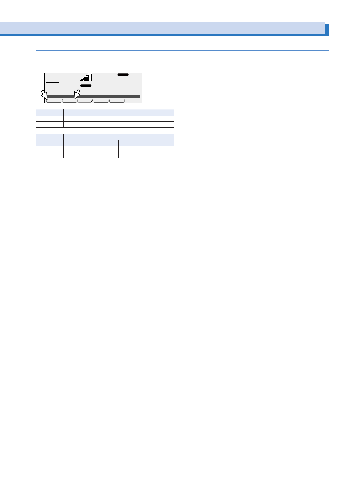
VMINVMAXDCVOLTACVOLT PROTECT
To set the AC voltage, press V and then ACVOLT (F1).
To set the DC voltage, press V and then DCVOLT (F2).
RESP.M
OUTPUT
OFF
6.87
ACVolt 7.5V
Item Title Description Valid modes
ACVOLT ACVolt Sets the AC voltage AC, AC+DC
DCVOLT DCVolt Sets the DC voltage DC, AC+DC
Output voltage setting range
AC voltage DC voltage
L range 0 V to 152.5 V -215.5 V to +215.5 V
H range 0 V to 305.0 V -431.0 V to +431.0 V
RANGE
rms rms
A
AC+DCLOAD
58.00
L
Hz
28.1
V
PCR-LE series 23
Page 24
Setting the Output Voltage (Cont.)
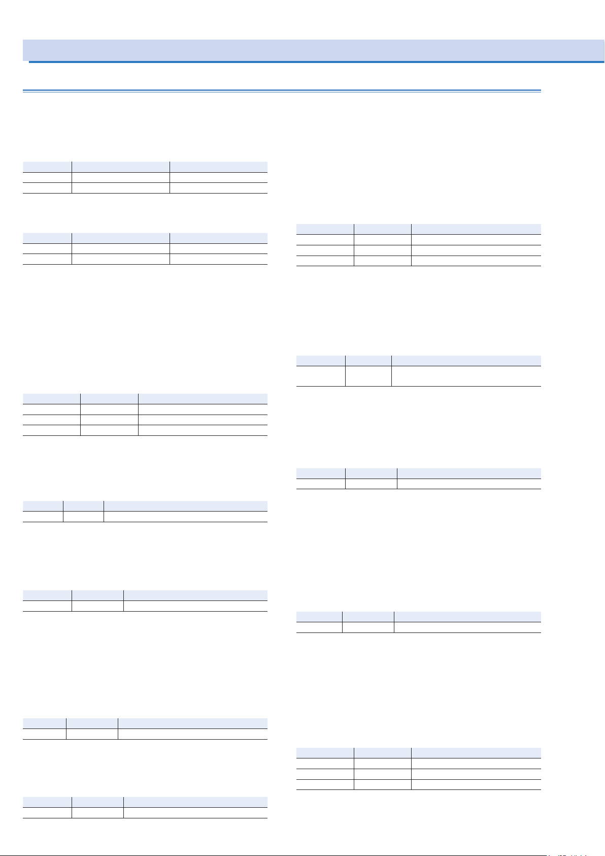
Single-phase, three-wire output (optional) voltage setup procedure
Be sure to set the output mode (single-phase, three-wire output
or two-phase output) before you set the voltage. -> p20
Voltage setting range
• Phase voltage setting range
AC voltege setting range DC voltage setting range
L range 0 V to 152.5 V -215.5 V to +215.5 V
H range 0 V to 305.0 V -431.0 V to +431.0 V
• Line voltage setting range
The line voltage is twice the phase voltage.
AC voltege setting range DC voltage setting range
L range 0 V to 305.0 V -431.0 V to +431.0 V
H range 0 V to 610.0 V -862.0 V to +862.0 V
AC mode
Specifying the AC voltage with phase voltages
To set all the phases at the same time, press V and then PHAS
VOLT (F1).
To set the U phase, press V, 1/2(F6), and then U VOLT(F1).
To set V phase, press V, 1/2(F6), and then V VOLT(F2).
With an unbalanced configuration, the unbalance icon is dis-
played.
Item Title Description
PHAS VOLT AC PhaseVolt Sets the AC voltage of all the phases
U VOLT U AC PhaseVolt Sets the AC voltage of U phase
V VOLT V AC PhaseVolt Sets the AC voltage of V phase
•
Sets the phase difference
You can set the phase difference between U and V. To do so, press V,
1/2 (F6), and then UV PHASE (F4). If you set the phase difference to
a value other than 180°, the unbalance icon is displayed.
Item Title Description
UV PHASE U V Phase
Sets the U-V phase difference (0 deg to 359 deg)
Specifying the AC voltage with line voltages
You can set the line voltage. The line voltage is valid when the
phase difference between U and V is 180°.
To do so, press V, and then LINE VOLT (F2).
Item Title Description
LINE VOLT AC LineVolt Sets the line voltage
DC mode
Specifying the DC voltage with phase voltages
Set a voltage that is 1/2 the voltage that is necessary between
the lines.
To set the DC voltage to assign to the U phase, press V and
then PHAS VOLT(F1). The V phase is automatically set to the
same amplitude as the U phase but with opposite polarity.
Item Title Description
PHAS VOLT DC PhaseVolt Sets the DC voltage
AC+DC mode
Specifying the AC voltage with phase voltages
To set all the phases at the same time, press V and then AC
PHAS VOLT (F1).
To set the U phase, press V, 1/x(F6), and then U ACVOLT(F1).
To set V phase, press V, 1/x(F6), and then V ACVOLT(F2) (x var-
ies depending on the selected output mode)
.
With an unbalanced configuration, the unbalance icon is displayed.
Item Title Description
AC PH VOLT AC PhaseVolt Sets the AC voltage of all the phases
U ACVOLT U AC PhaseVolt Sets the AC voltage of U phase
V ACVOLT V AC PhaseVolt Sets the AC voltage of V phase
•
Sets the phase difference (two-phase output (2P MODE ON)
only)
You can set the phase difference between U and V. To do so,
press V, 1/4 (F6), and then UV PHASE (F4). If you set the phase
difference to a value other than 180°, the unbalance icon is displayed.
Item Title Description
UV PHASE U V Phase Sets the U-V phase difference (0 deg to
359 deg)
Specifying the AC voltage with line voltages
You can set the line voltage. In two-phase output (2P MODE
ON) ,the line voltage is valid when the phase difference between U and V is 180°.
To do so, press V, and then LINE VOLT (F2).
Item Title Description
LINE VOLT AC LineVolt Sets the line voltage
Setting the DC voltage
Set the DC voltage with phase voltages.
• Single-phase three-wire output (2P MODE OFF)
Set a voltage that is 1/2 the voltage that is necessary between
the lines.
To set the DC voltage to assign to the U phase, press V and
then DC PHAS VOLT(F3). The V phase is automatically set to
the same amplitude as the U phase but with opposite polarity.
Item Title Description
DC PH VOLT DC PhaseVolt Sets the DC voltage
• Two-phase output (2P MODE ON)
To set all the phases at the same time, press V and then DC PH
VOLT (F3).
To set the U phase, press V, 1/4(F6), 2/4(F6), and then U
DCVOLT(F1). To set V phase, press V, 1/4(F6), 2/4(F6), and
then V DCVOLT(F2).
With an unbalanced configuration, the unbalance icon is displayed.
Specifying the DC voltage with line voltages
You can set the line voltage.
To do so, press V, and then LINE VOLT (F2).
Item Title Description
LINE VOLT DC LineVolt Sets the line voltage
Item Title Description
DC PH VOLT DC PhaseVolt Sets the DC voltage of all the phases
U DCVOLT U DC PhaseVolt Sets the DC voltage of U phase
V DCVOLT V DC PhaseVolt Sets the DC voltage of V phase
24 PCR-LE series
Page 25
Three-phase output (optional) voltage setup procedure
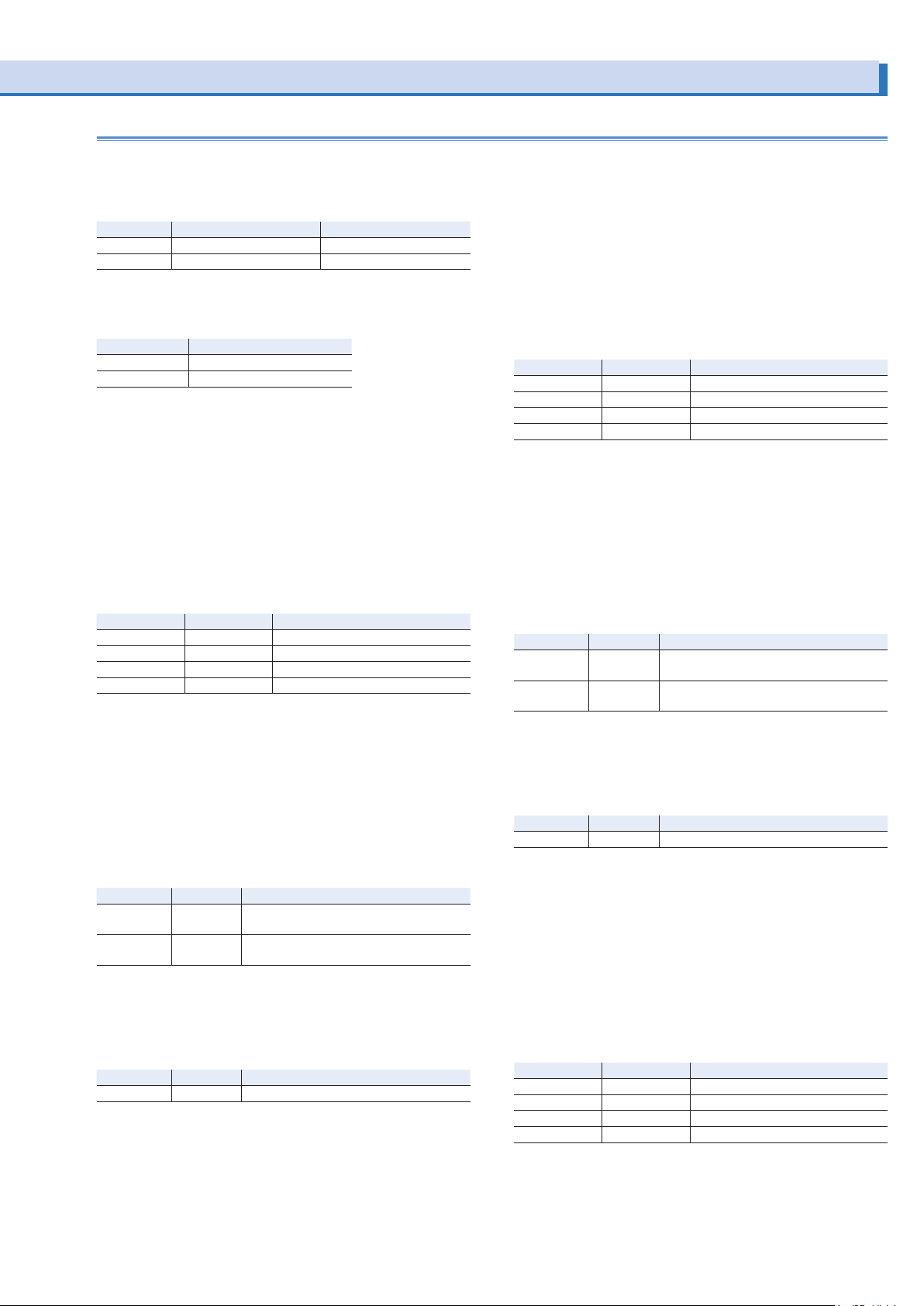
Voltage setting range
• Phase voltage setting range
AC voltege setting range DC voltage setting range
L range 0 V to 152.5 V -215.5 V to +215.5 V
H range 0 V to 305.0 V -431.0 V to +431.0 V
• Line voltage setting range
The line voltage is √3 times the phase voltage.
AC voltage setting range
L range 0 V to 264.1 V
H range 0 V to 528.2 V
AC Mode
Specifying the AC voltage with phase voltages
To set all the phases at the same time, press V and then PHAS
VOLT (F1).
To set the U phase, press V, 1/2(F6), and then U VOLT(F1).
To set V phase, press V, 1/2(F6), and then V VOLT(F2).
To set W phase, press V, 1/2(F6), and then W VOLT(F3).
With an unbalanced configuration, the unbalance icon is dis-
played.
Item Title Description
PHAS VOLT AC PhaseVolt Sets the AC voltage of all the phases
U VOLT U AC PhaseVolt Sets the AC voltage of U phase
V VOLT V AC PhaseVolt Sets the AC voltage of V phase
W VOLT W AC PhaseVolt Sets the AC voltage of W phase
•
Sets the phase difference
You can set the phase differences between U and V and between U and W.
To set the phase difference between U and V, press V, 1/2 (F6),
and then UV PHASE (F4). To set the phase difference between
U and W, press V, 1/2 (F6), and then UW PHASE (F5).
If the phase difference between U and V is set to a value other
than 120° or the phase angle between U and W is set to a
value other than 240°, the unbalance icon is displayed.
Item Title Description
UV PHASE U V Phase Sets the U-V phase difference (0 deg to
UW PHASE U W Phase Sets the U-W phase difference (0 deg to
359 deg)
359 deg)
Specifying the AC voltage with line voltages
You can set the line voltage when the phase difference between
U and V is 120° and the phase difference between U and W is
240°. To do so, press V and then LINE VOLT (F2).
Item Title Description
LINE VOLT AC LineVolt Sets the line voltage
AC+DC Mode
Specifying the AC voltage with phase voltages
To set all the phases at the same time, press V and then AC PH
VOLT (F1).
To set the U phase, press V, 1/4(F6), and then U AC VOLT(F1).
To set V phase, press V, 1/4(F6), and then V ACVOLT(F2).
To set W phase, press V, 1/4(F6), and then W ACVOLT(F3).
With an unbalanced configuration, the unbalance icon is dis-
played.
Item Title Description
AC PH VOLT AC PhaseVolt Sets the AC voltage of all the phases
U ACVOLT U AC PhaseVolt Sets the AC voltage of U phase
V ACVOLT V AC PhaseVolt Sets the AC voltage of V phase
W ACVOLT W AC PhaseVolt Sets the AC voltage of W phase
•
Sets the phase difference
You can set the phase differences between U and V and between U and W.
To set the phase difference between U and V, press V, 1/4 (F6),
and then UV PHASE (F4). To set the phase difference between
U and W, press V, 1/4 (F6), and then UW PHASE (F5).
If the phase difference between U and V is set to a value other
than 120° or the phase angle between U and W is set to a
value other than 240°, the unbalance icon is displayed.
Item Title Description
UV PHASE U V Phase Sets the U-V phase difference (0 deg to
UW PHASE U W Phase Sets the U-W phase difference (0 deg to
359 deg)
359 deg)
Specifying the AC voltage with line voltages
You can set the line voltage when the phase difference between
U and V is 120° and the phase difference between U and W is
240°. To do so, press V and then AC LIN VOLT (F2).
Item Title Description
AC LIN VOLT AC LineVolt Sets the line voltage
Setting the DC voltage
Set the DC voltage with phase voltages.
To set all the phases at the same time, press V and then DC PH
VOLT (F3).
To set the U phase, press V, 1/4(F6), 2/4(F6), and then U
DCVOLT(F1). To set V phase, press V, 1/4(F6), 2/4(F6), and
then V DCVOLT(F2). To set W phase, press V, 1/4(F6), 2/4(F6),
and then W DCVOLT(F3).
With an unbalanced configuration, the unbalance icon is displayed.
Item Title Description
DC PH VOLT DC PhaseVolt Sets the DC voltage of all the phases
U DCVOLT U DC PhaseVolt Sets the DC voltage of U phase
V DCVOLT V DC PhaseVolt Sets the DC voltage of V phase
W DCVOLT W DC PhaseVolt Sets the DC voltage of W phase
PCR-LE series 25
Page 26
Setting the Frequency
AC+DCLOAD
ACLOAD
FORCESAFE
You can set the frequency in AC mode and AC+DC mode. The
F key is disabled in DC mode.
You can set the frequency while output is on or off.
Set the frequency limit to prevent the PCR-LE Series from gen-
erating a frequency that is greater than is necessary.
Frequency setup procedure
Press F and then FREQ (F1) to set the frequency.
Hz
28.1
FMINFMAXFREQ
RESP.M
V
OUTPUT
OFF
6.87
Freq 50.00Hz
58.00
RANGE
L
rms rms
A
Turning Output On and Off
WARNING
Risk of electric shock.
Do not touch the OUTPUT terminal block, the outlets,
and the sensing terminal block.The time required for the
internal capacitors to discharge when no load is connected is approximately 0.1 seconds.
In DC mode, even if the output is off, if a capacitor, battery, or similar item is connected as the load, a voltage
remains in the device that is connected to the OUTPUT
terminal block, the outlets, and the sensing terminal
block until the load’s energy is discharged.
Item Title Description Valid modes
FREQ Freq Sets the frequency (1.00 Hz to
999.9 Hz)
AC and AC+DC
CAUTION
When you turn the output on, several volts of undershoot or
overshoot may occur for several tens of microseconds.
Each time that you press OUTPUT, the output toggles between
on and off.
•
Output on
“OUTPUT ON” is shown on the display.
A voltage and frequency that correspond to the output mode
and output range that you have specified are generated.
RESP.M
L
L
50.00
50.00
ACLOAD
ACLOAD
Hz
1.1
Hz
1.1
RESP.M
V
V
OUTPUT
ON
0.04
•
Output off
“OUTPUT OFF” is shown on the display.
OUTPUT
OFF
0.04
RANGE
rms rms
A
RANGE
rms rms
A
If a protection function is activated and the product is in the
alarm state, the output is turned off.
power is turned on
You can select the state of the output when the POWER switch
is turned on.
Press OTHERS (SHIFT+MEMORY), 1/3 (F6), and then PON
OUTP(F4) to set the state of output.
OUTPUT
OFF
6.87
OTHER. MEMU
PowerON OutputOn SAFE
Item Title Description
26 PCR-LE series
SAFE PowerOn
FORCE The output is on when the power is turned on.
A
COMPEN RESPVCC
OutputOn
99.00
RANGE
L
rms rms
PON OUTP
The output is off when the power is turned on.
RESP.M
Hz
28.1
V
2/3FILE
Page 27
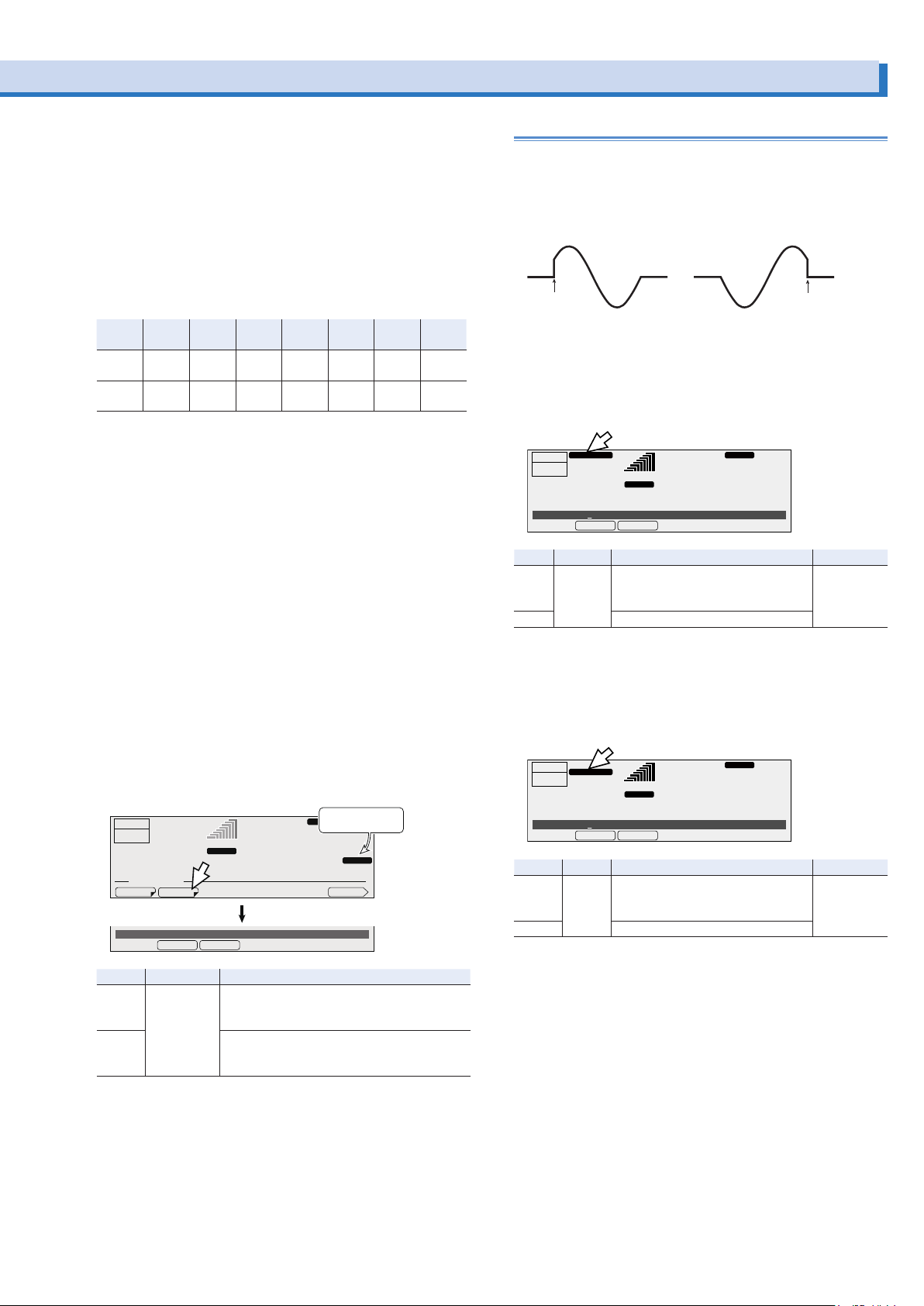
Impedance when the output is off
OFFON
Output on Output off
Displayed when you select “FIXED”
Displayed when you select “FIXED”
The internal circuits and the output of the PCR-LE Series are
not separated by a mechanical switch or relay. The PCR-LE
Series turns the output off by electrically increasing the output
impedance. This enables you to turn the output on and off without chattering. When the output is off, the output is set to high
impedance, and the output voltage is nearly 0 V.
Even when the output is on, the following impedances are
present, so if the load is a battery or a similar device, a slight
current may flow into the PCR-LE Series, and the load may be
discharged.
PCR
PCR
8 kΩ
PCR
2000LE
Approx.
4 kΩ
Approx.
16 kΩ
500LE
1000LE
L range Approx.
H range Approx.
Voltage surge suppression when the output is
16 kΩ
64 kΩ
Approx.
Approx.
32 kΩ
PCR
3000LE
Approx.
2.7 kΩ
Approx.
10.7 kΩ
PCR
4000LE
Approx.
2 kΩ
Approx.
8 kΩ
PCR
6000LE
Approx.
1.3 kΩ
Approx.
5.3 kΩ
PCR
9000LE
Approx.
0.89 kΩ
Approx.
3.6 kΩ
turned off
You can set the voltage surge suppression that is activated
when the output is turned off.
When the output is off, the output of this product is at high impedance.
If voltage surge suppression is set to ON (factory default setting), immediately after the output is turned off, the output
voltage is set to 0 V (low output impedance), and then the
impedance is changed to high. To prevent large overshooting
and undershooting by the load immediately after the output is
turned off, we recommend that you use the PCR-LE Series with
the voltage surge suppression set to on.
When voltage surge suppression is on, an unexpected current
may flow through the product immediately after the output is
turned off depending on the connected load (power conditioner, regenerative inverter, battery, etc.). This may affect the test.
Turn voltage surge suppression off for the above loads.
Press CONFIG (SHIFT+OPR MODE), 1/2 (F6), and then SURGE
S (F2) to set voltage surge suppression.
Display when you
RESP.M
L
50.00
ACLOAD
Hz
0.1
VMINVMAXDCVOLTACVOLT PROTECT
select OFF
SURGE
V
2/2
OUTPUT
OFF
0.1
CONFIG. MEMU
DATE TIM
Surge suppresstion ON
SURGE S
RANGE
rms rms
A
Output on/off phase control
You can set the AC mode output on/off phase. You can set the
output on and output off phases separately. This is valid in AC
mode and AC+DC mode.
During single-phase, three-wire output and three-phase output
(optional), set the phase of the U-phase unit.
Output on phase setup procedure
When you are controlling the output on phase, set the phase
angle as well.
Press ON PHASE (SHIFT+7) to set the output on phase.
ON PHASE
OUTPUT
OFF
6.87
ON Phase 0deg
Item Title Description Valid modes
FIXED ON Phase Sets the output on phase angle (0
FREE The output on phase is not controlled.
Output off phase setup procedure
A
FREEFIXED
deg to 359 deg)
The output on phase is controlled.
58.00
RANGE
L
rms rms
When you are controlling the output of phase, set the phase
angle as well.
Press OFF PHASE (SHIFT+4) to set the output off phase.
OUTPUT
OFF PHASE
OFF
6.87
OFF Phase 0deg
Item Title Description Valid modes
FIXED OFF
Phase
FREE The output off phase is not controlled.
A
FREEFIXED
Sets the output off phase angle (0
deg to 359 deg)
The output off phase is controlled.
58.00
RANGE
L
rms rms
RESP.M
ACLOAD
Hz
28.1
RESP.M
ACLOAD
Hz
28.1
V
AC and
AC+DC
V
AC and
AC+DC
Item Title Description
ON Surge sup-
OFF Voltage surge suppression off
pression
Voltage surge suppression on
The output is turned off after the output voltage
is set to 0 V.
The output is turned off with the output left at
high impedance.
PCR-LE series 27
Page 28
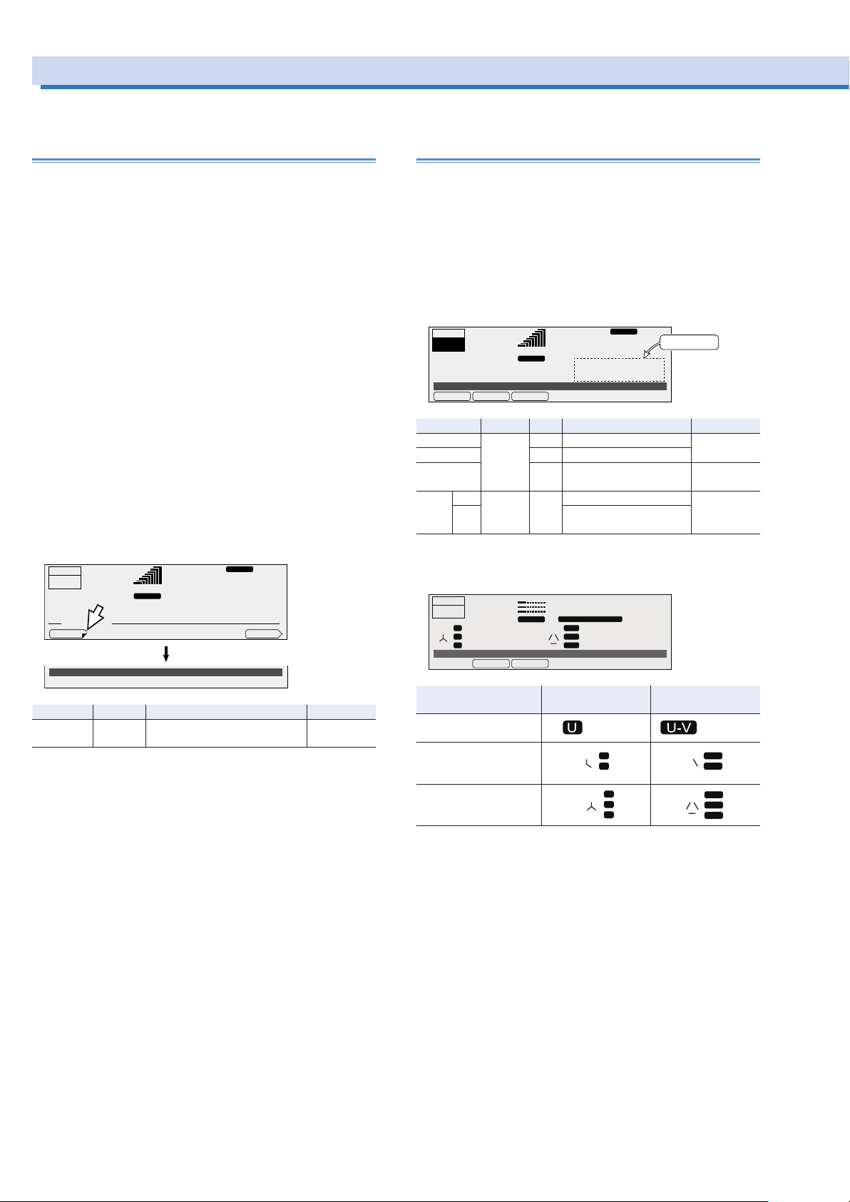
Displaying Measured Values
AC+DCLOAD
AC
U
U
U-V
U
U
W
W
You can monitor the present output value. When the output is off, this is nearly 0.
Setting the aperture time (measurement time)
With a longer aperture time, the measurements become more
stable, but it takes longer to update the display of the measured values. Guidelines for the aperture time when the signal
includes an AC component are given below.
• When the period of the AC is known, you can obtain the most
accurate measurement results if you set the aperture time to
an integer multiple of the period.
Example: If the period of the AC component is 0.1 s, you can
obtain the best results in the shortest time if you set the aperture time to 0.1 s.
• When the period of the AC component is unknown, you can
obtain comparatively stable measurement results if you set
the aperture time to a value that is at least 10 times the expected period.
If the period is set greater than the aperture time, line voltages
cannot be measured correctly.
If the harmonic current analysis function is in use and the period is set greater than the aperture time, correct measurements
cannot be made.
Press OTHERS (SHIFT+MEMORY), 1/3 (F6), 2/3 (F6), and then
APERTUR (F1) to set the aperture time.
Factory default is 0.4 s.
RESP.M
L
99.00
ACLOAD
Hz
28.1
V
3/3
All
OUTPUT
OFF
6.87
OTHER. MEMU
APERTUR
Aperture Time 0.4 s
Item Title
APERTUR Aperture
Time
RANGE
rms rms
A
Description Valid modes
Sets the aperture time (0.1 s to
1.0 s, resolution: 0.001 s).
The aperture time setting was added in firmware version 5.00.
As a result, the function for averaging measured values that
was available in firmware version 4.99 and earlier is no longer
available.
Displaying the voltage
The measured voltage is displayed in the status, measuredvalue, and setting display area.
The voltage is displayed as an rms value, peak value, or average value.
To switch the display, press V-MEAS (SHIFT+V) to select the
item that you want to display.
During single-phase, three-wire output and three-phase output
(optional), you can select to display phase voltage or line voltage.
OUTPUT
ON
50.78
V-Meas RMS
A
AVEPEAKRMS
99.00
RANGE
L
pk rms
Item Title Unit Description Valid modes
RMS V-Meas V rms Displays the rms voltage All
PEAK V pk Displays the peak voltage
AVE V ave Displays the average volt-
*1
ON V-Line V rms Displays the line voltage AC and DC
LINE
age
OFF Displays the phase volt-
age
*1. Single-phase three-wire output or three-phase output (optional) only
Line voltage display and Phase voltage display (optional)
OUTPUT
OFF
U
VW
V-Line ON
V-LINE OFF (Phase voltage
When a single phase is
displayed
When all phases are
displayed (single-phase,
three-wire output)
When all phases are
displayed (three-phase
output)
LOAD
UNBAL.PHAS, VOLT
RANGE L
0.01
A
0.00
A
rms rms
0.00
A
OFFON
U-VU
U
V-WV
VW
W-UW
display)
RESP.M
Hz
102.3
V
The voltage
DC and
AC+DC
99.00
Hz
0.0
V
0.1
V
0.0
V
ON (Line voltage
display)
U example U-V example
V
V
U
V
V
V-U
V
U-V
U
V-W
VW
W-U
28 PCR-LE series
Page 29
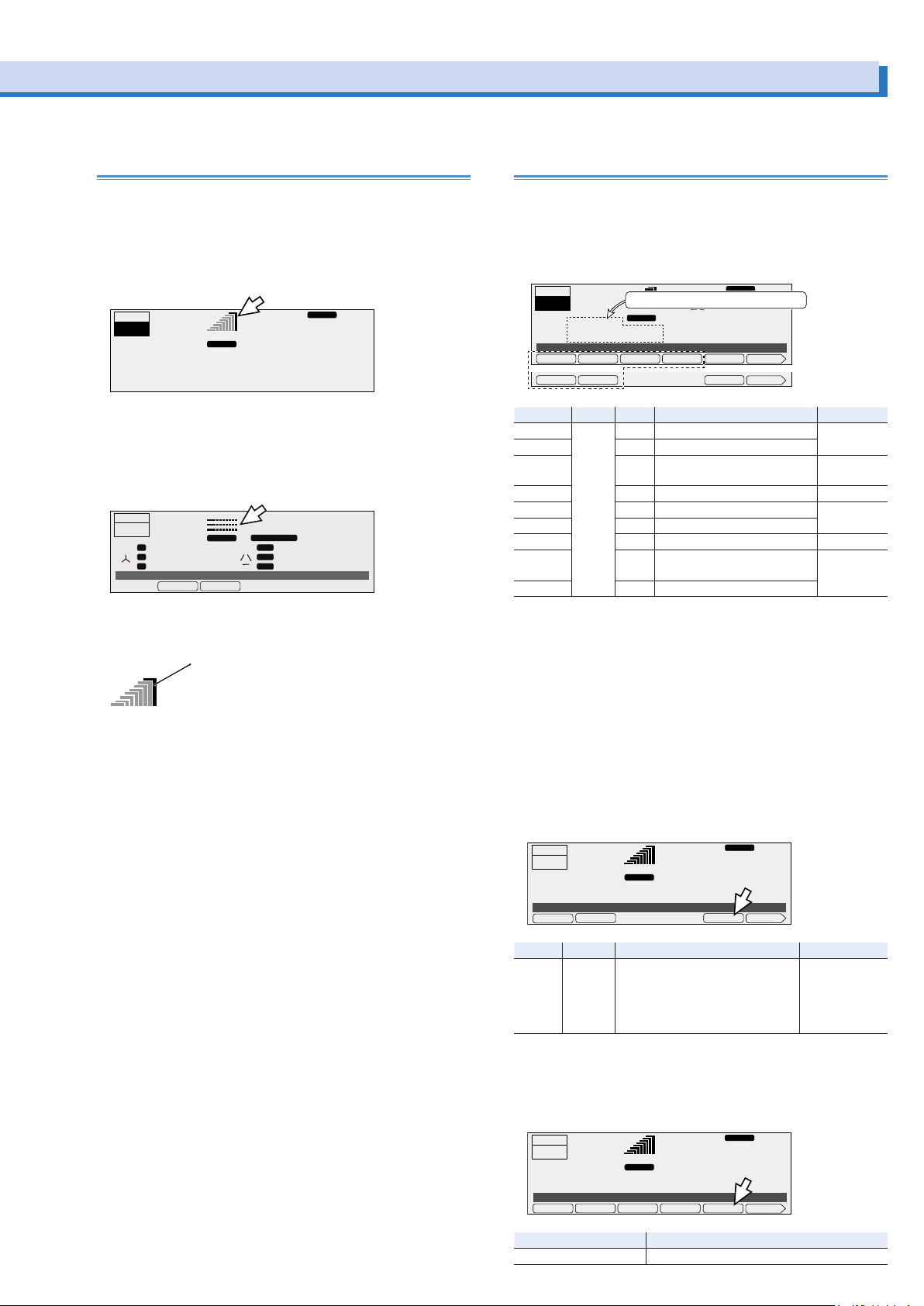
Load level meter
Full scale bar
DCLOAD
PKCLRPAVEPEAKRMS 1/2
DCLOAD
Displaying the current, power, and power factor
The load level meter displays the ratio of the output current
(which is detected as the current flowing through the load) to
the rated current on a bar graph. This can be used to determine the approximate output current supply capability. The full
scale of the load level meter is 1.1 times the rated current or
the current limit, whichever is less.
RESP.M
50.00
AC RESP.MLOAD
Hz
1.1
V
OUTPUT
ON
0.04
RANGE L
rms rms
A
During single-phase, three-wire output (optional), the load level
meter displays the U phase at the top and then the V phase.
During three-wire output (optional), the load level meter displays the U phase at the top followed by the V phase and W
phase.
OUTPUT
OFF
0.01
U
VW
V-Line ON
2.22
LOAD
RANGE
A
1.11
A
rms rms
A
OFFON
L
U
99.00
UNBALANCE
U-VU
V-WV
VW
W-UW
AC
Hz
0.2
V
1.2
V
2.3
V
The full scale bar (the right-most bar that lights red) of the load
The rms current, peak current, average current, power, apparent power, or power factor is displayed in the status, measuredvalue, and setting display area.
To switch the display, press I/P/S/λ-MEAS (SHIFT+I) to select
the item that you want to display.
dc
28.1
PKCLRPPEAK
IPK TIM 2/2λS
RESP.M
V
OUTPUT
ON
6.87
I/P/S/λ-Meas RMS
Item Title Unit Description Valid modes
RMS I/P/S/
PEAK A pk Displays the peak current
AVE A ave Displays the average current DC and
P W/kW Displays the power All
S VA Displays the apparent power AC and
λ λ
TOTAL P
TOTAL S
TOTAL
*1. Single-phase three-wire output or three-phase output (optional) only
-Meas
λ
*1
*1
*1
λ
The current, power, or power factor
RANGE
L
rms rms
A
AVERMS 1/2
A rms Displays the rms current All
Displays the power factor
W Displays the total power All
VA Displays the total apparent
power
Displays the total power factor
λ
level meter lights on the verge of an overload.
Holding the peak current
The peak current measurement is displayed as an absolute
value of the maximum instantaneous current measured. In DC
mode, even if you are generating negative voltage, the peak
When the PCR-LE is on the verge of an overload, the internal
temperature increases. Even if the load is reduced, the full
scale bar may continue to light dimly in red. When cooling is
complete, the full scale bar turns off.
If overload conditions occur repeatedly while the full scale bar
is lit, an alarm (ALM-06: OVERLOAD) may be generated.
Rated current and load level meter display
The output current varies depending on the load. The rated
current is automatically derated (reduced) depending on the
output conditions (output voltage, frequency, and load power
factor).
For details of rated output current, see ”About the output and
the load”. -> p94
The rated current is automatically derated (reduced) depending on the output conditions (output voltage, frequency, and
load power factor).
measured current is displayed as a positive value.
If you have selected the peak current measurement as the
measured value that is displayed, you can hold the peak current measurement.
Press I/P/S/l-MEAS (SHIFT+I), 1/2 (F6), and then IPK TIM (F5)
to set the hold time.
RESP.M
OUTPUT
OFF
6.87
IPk Time ∞
Item Title Description Valid modes
IPK TIM IPk Time Sets the hold time (0 s to 10 s or ∞).
RANGE L
pk rms
A
If you use the numeric key pad to
specify a value that is greater than
or equal to 10, infinity (∞) will be
specified.
DCLOAD
dc
28.1
IPK TIM 2/2λS
V
The following shows an example of how to calculate the rated
current on the PCR1000LE.
• If the output voltage is 80 V, the load power factor is 0.6, and
the output frequency is 50 Hz,
the rated current is 10 A × 0.825 = 8.25 A.
• If the output voltage is 250 V, the load power factor is 0.4,
and the output frequency is 60 Hz,
the rated output current is 1 000 W/250 V × 0.65 = 2.6 A.
• If the output voltage is 80 V, the load power factor is 0.6, and
the output frequency is 10 Hz,
the rated current is 10 A × 0.775 = 7.75 A (≤ 8.25 A).
Clearing the peak current
Press I/P/S/l-MEAS (SHIFT+I) and then PKCLR (F5) to clear the
peak current.
dc
28.1
RESP.M
V
OUTPUT
OFF
6.87
I/P/S/λ-Meas RMS
Item Description
PKCLR Clears the peak current
RANGE
L
pk rms
A
PCR-LE series 29
AC+DC
AC+DC
AC and
AC+DC
All (only when
the peak current measurement is being
displayed)
Page 30
Limit Values and Protection Functions
This product has the following limit functions and protection
functions.
•
Limit Functions
Limits can be placed on the PCR-LE Series output voltage
setting and frequency setting. They prevent damage to the
load caused by mistaken operations and limit the current that
flows through the load.
•
Protection Functions
Protection functions apply limits when there is a danger of
damaging the internal circuitry of the PCR-LE Series or to
protect the DUT.
When a protection function is activated, an alarm (ALM-xx) or
a trouble indication (TRBL-xx) is generated, and the output is
turned off.
Item Function Description Output off
Voltage upper limit
Voltage lower limit
Output overvoltage protection (OVP)
Output undervoltage protection (UVP)
Frequency upper limit
Frequency lower limit
Current limit
Peak current limit
Internal semiconductor
protection (OCP)
Input voltage drop protection
Overload protection
Overheat protection (OHP)
Limit You will not be able to specify voltages that are outside
of the set limit range.
Protection If the measured voltage exceeds the OVP value, an
alarm occurs, and the output turns off.
Protection If the measured voltage falls below the UVP value, an
alarm occurs, and the output turns off.
Limit You will not be able to specify frequencies that are
outside of the set limit range.
Limit If the upper limit is exceeded, the output turns off, or
the output voltage is controlled so that the limit value is
not exceeded. You cannot set the lower limit. You can
set how the PCR-LE Series behaves when the limit is
exceeded (whether to turn off the output or control the
output voltage).
If you select to turn off the output, you can set the time
that must elapse before the output is turned off when
the current limit is exceeded.
If you select to control the output voltage, the following
functions will not be available.
• Turn soft start on (set the rise time)
• Execute power line abnormality simulations
• Run sequences
• Use the compensation function’s software sensing
and regulation adjustment
Limit This function instantly limits the peak output current.
You can set positive and negative limits.
Protection This function protects the internal semiconductors of
the PCR-LE Series. If a temporary overcurrent—such
as an inrush current—occurs, an alarm occurs, and the
output turns off.
Protection If the input voltage falls below the rating, a trouble indi-
cation occurs, and the output turns off.
Protection If the output current exceeds the rated current or cur-
rent limit, an alarm occurs, and the output turns off.
Protection If the internal temperature increases abnormally, an
alarm occurs, and the output turns off.
No
Yes
Yes
No
Selectable
No
Yes
Yes
Yes
Yes
30 PCR-LE series
Page 31
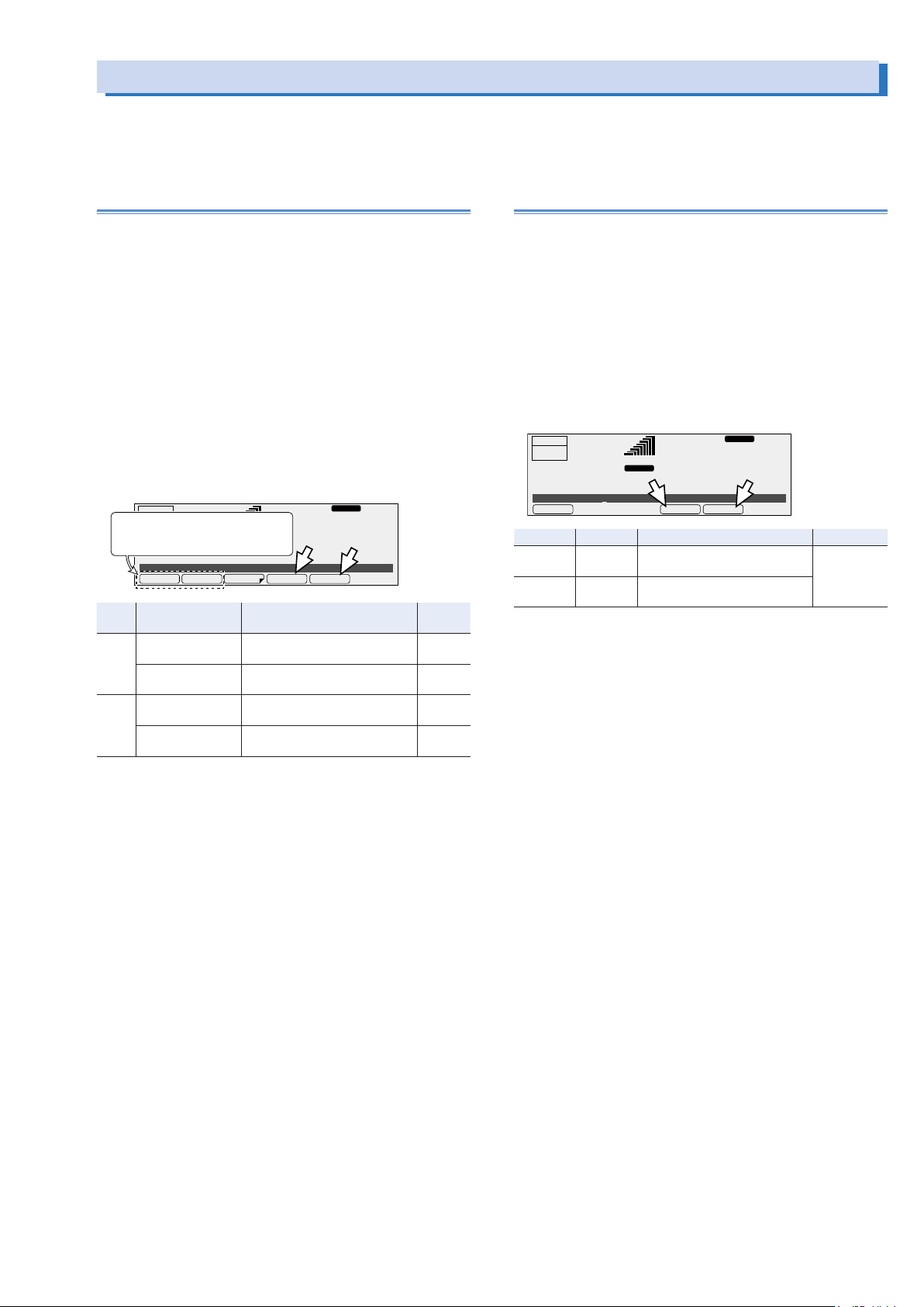
Setting Limits
AC+DCLOAD
AC+DCLOAD
Limits can be placed on the PCR-LE Series output voltage setting and frequency setting. They prevent damage to the load caused by
mistaken operations and limit the current that flows through the load. You can set limits in advance according to the load conditions.
You can set these values while output is on or off.
Voltage upper and lower limits
Limits can be placed on the PCR-LE Series output setting. They
prevent damage to the load caused by mistaken operations.
You can set limits in advance according to the load conditions.
After you set the voltage limits, you will no longer be able to
specify voltage values that are outside of the range that you
have set. The only exception is 0 V. You can still use the numeric keypad to specify this value.
Set the limits so that the lower limit is less than or equal to the
upper limit.
In AC+DC mode, there are AC limits and DC limits. Check the
title in the entry area, and then set the value.
During single-phase, three-wire output and three-phase output
(optional), set the limits using phase voltages.
To set the voltage upper limit, press V and then VMAX (F4).
To set the voltage lower limit, press V and then VMIN (F5).
OUTPUT
In AC+DC mode,
OFF
use these function keys to switch
between the AC and DC limits.
Item Title Description Valid
VMAX ACVoltMax
VMIN ACVoltMin
*1. The display during single-phase, three-wire output and three-phase output
(optional)
6.87
ACVolt 7.5V
AC PhaseVoltMax
DCVoltMax
DC PhaseVoltMax
AC PhaseVoltMin
DCVoltMin
DC PhaseVoltMin
A
*1
*1
58.00
RANGE
L
rns rms
Sets the AC voltage upper limit
*1
(0.0 V to 305.0 V)
Sets the DC voltage upper limit
*1
(-431.0 V to 431.0 V)
Sets the AC voltage lower limit
(0.0 V to 305.0 V)
Sets the DC voltage lower limit
(-431.0 V to 431.0 V)
RESP.M
Hz
28.1
VMINVMAXDCVOLTACVOLT PROTECT
V
modes
AC and
AC+DC
DC and
AC+DC
AC and
AC+DC
DC and
AC+DC
Frequency upper and lower limits
Limits can be placed on the PCR-LE Series output setting. They
prevent damage to the load caused by mistaken operations.
You can set limits in advance according to the load conditions.
After you set the frequency limits, you will no longer be able to
specify frequency values that are outside of the range that you
have set.
You cannot set these values in DC mode.
Set the limits so that the lower limit is less than or equal to the
upper limit.
Press F and then FMAX (F4) to set the frequency upper limit.
Press F and then FMIN (F5) to set the frequency lower limit.
OUTPUT
OFF
6.87
Freq 50.00Hz
Item Title Description Valid modes
FMAX FreqMax Sets the frequency upper limit
FMIN FreqMin Sets the frequency lower limit
A
58.00
RANGE
L
rns rms
(1.00 Hz to 999.9 Hz)
(1.00 Hz to 999.9 Hz)
RESP.M
Hz
28.1
FMINFMAXFREQ
V
AC and
AC+DC
PCR-LE series 31
Page 32
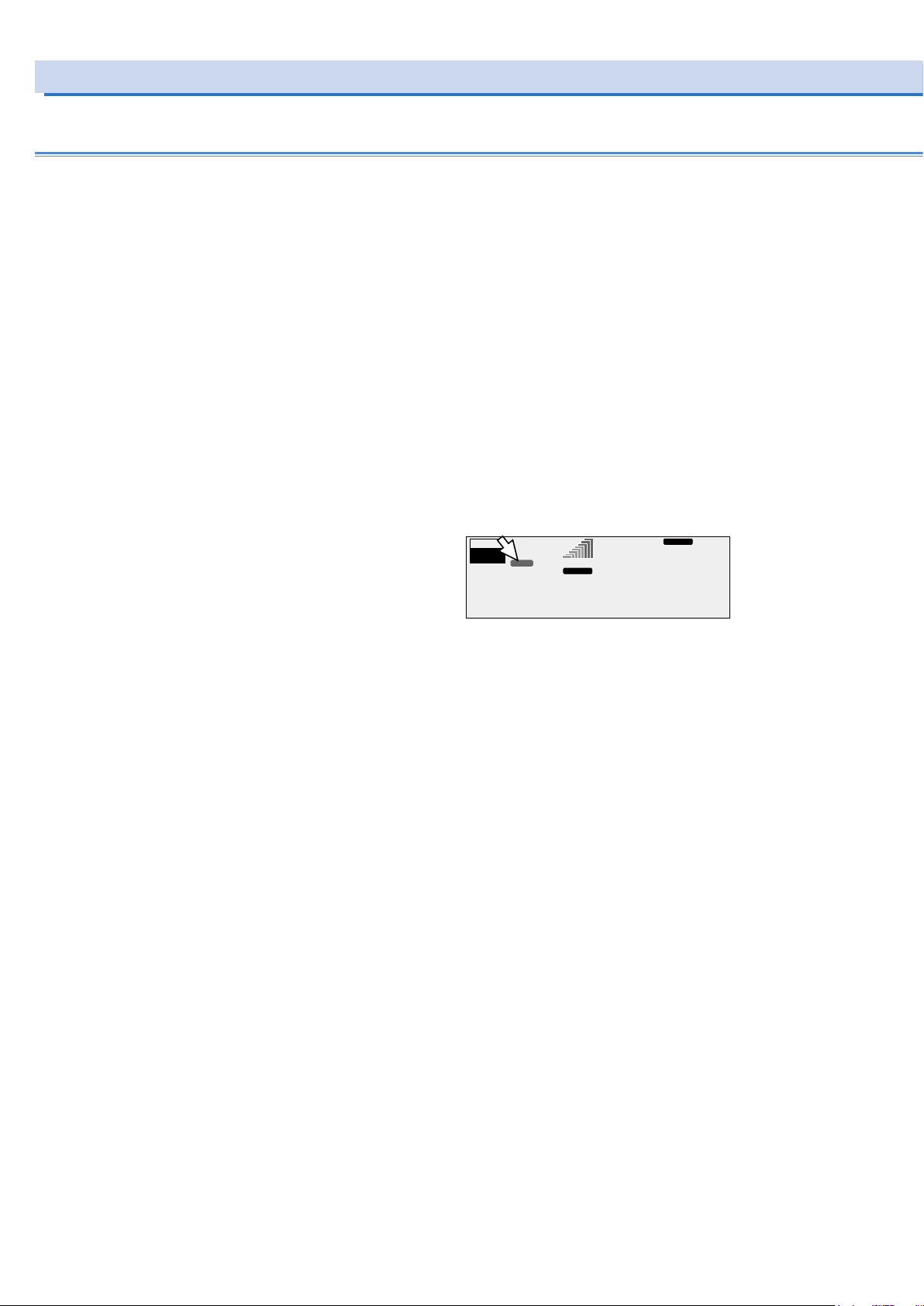
Setting Limits (Cont.)
Current limit and peak current limits
Limits can be placed on the current that flows through the load.
There is a current limit, a positive peak current limit, and a negative peak current limit. You can set limits according to the load
conditions.
•
Current limit
You can set the output current’s upper limit. You cannot set
the lower limit.
The limit operates on the rms value of the output current.
You can set how the PCR-LE Series acts (turn the output off/
do not turn the output off) when the current limit is exceeded.
The actual current limit is activated at 1.1 times the rated cur-
rent or the current limit, whichever is less. The rated current
is automatically derated (reduced) depending on the output
conditions (output voltage, frequency, and load power factor).For details of rated output current, see ”About the output
and the load”. -> p94
•
Positive peak current limit and negative peak current limit
You can set positive and negative peak current limits.
These instantly limit the peak output current.
If the peak current approaches the peak current limit (ap-
proximately 94 % of the peak current limit), “IPK.LIM” is displayed.
Setting the peak current limits does not change the load level
meter’s full scale.
RESP.M
L
99.00
ACLOAD
Hz
102.3
V
OUTPUT
ON
50.78
IPK.LIM
RANGE
pk rms
A
32 PCR-LE series
Page 33
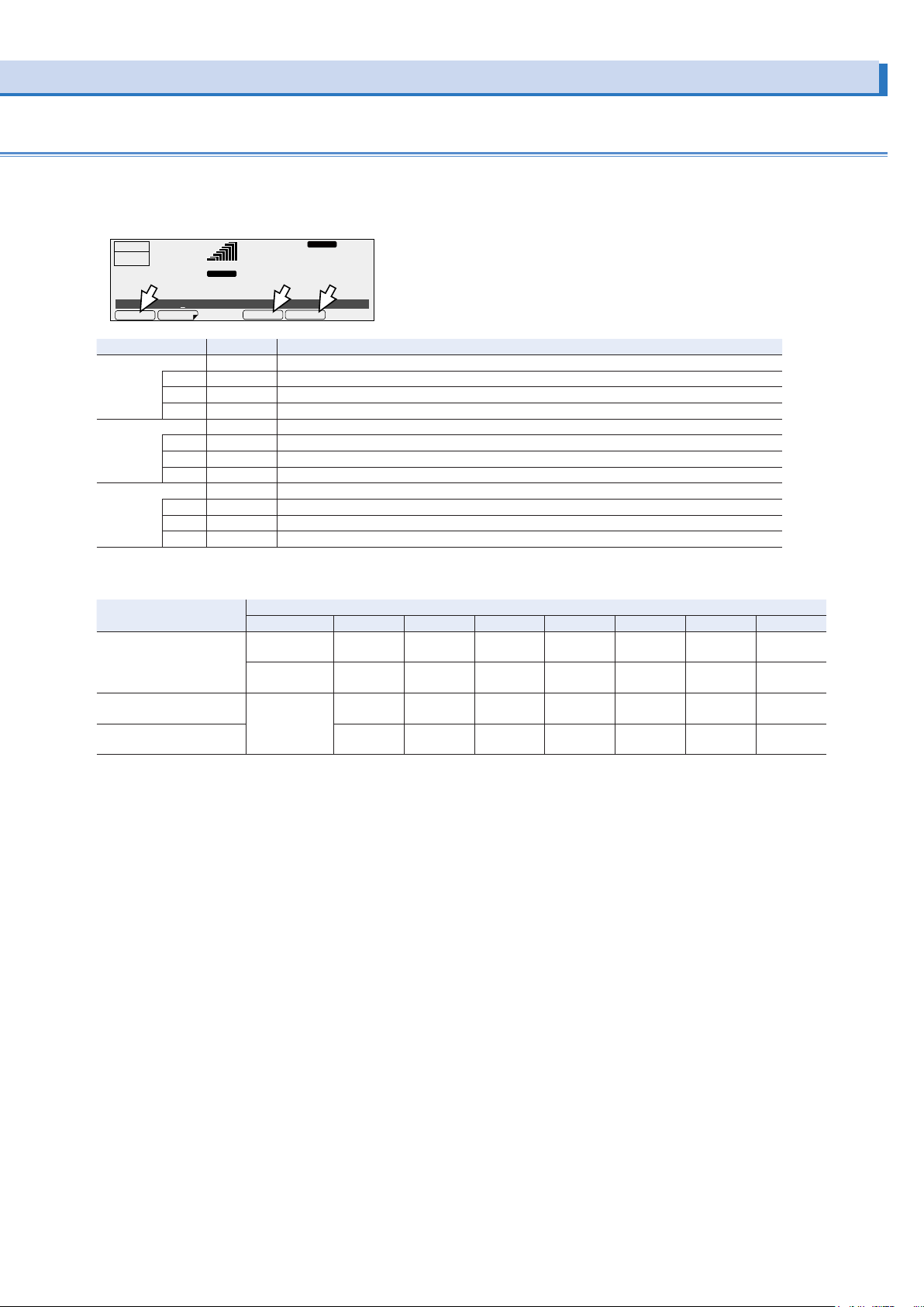
Press I and then ILIMIT (F1) to set the current limit.
DCLOAD
Press I and then +IPKLIM (F4) to set the positive peak current limit.
Press I and then -IPKLIM (F5) to set the negative peak current limit.
dc
28.1
-IPKLIMILIMIT
RESP.M
V
5.50 A
3.85 A
22.00 A
-0.50 A to
-22.00 A
1.00 A to
11.00 A
0.70 A to
7.70 A
1.00 A to
44.00 A
-1.00 A to
-44.00 A
2.00 A to
22.00 A
1.40 A to
15.40 A
2.00 A to
88.00 A
-2.00 A to
-88.00 A
3.00 A to
33.00 A
2.10 A to
23.10 A
3.00 A to
132.0 A
-3.00 A to
-132.0 A
4.00 A to
44.00 A
2.80 A to
30.80 A
4.00 A to
176.0 A
-4.00 A to
-176.0 A
6.00 A to
66.00 A
4.20 A to
46.20 A
6.00 A to
264.0 A
-6.00 A to
-264.0 A
OUTPUT
OFF
6.87
ILimit 3.85A
TRIP
RANGE
L
pk rms
A
+IPKLIM
Item Title Description
ILIMIT ILimit Sets the current limit (the rated current × 0.1 to the rated current × 1.1)
+IPKMAX +IPKLimit Sets the positive peak current limit (the rated current × 0.1 to the rated current × 4.4)
-IPKMAX -IPKLimit Sets the negative peak current limit (the rated current × 0.1 to the rated current × 4.4)
*1. Single-phase three-wire output or three-phase output (optional) only
*2. Three-phase output (optional) only
*1
U ILimit Sets the current limit of U phase (the rated current × 0.1 to the rated current × 1.1)
U
*1
V ILimit Sets the current limit of V phase (the rated current × 0.1 to the rated current × 1.1)
V
*2
W ILimit Sets the current limit of W phase (the rated current × 0.1 to the rated current × 1.1)
W
*1
U +IPKLimit Sets the positive peak current limit of U phase (the rated current × 0.1 to the rated current × 4.4)
U
*1
V +IPKLimit Sets the positive peak current limit of V phase (the rated current × 0.1 to the rated current × 4.4)
V
*2
W +IPKLimit Sets the positive peak current limit of W phase (the rated current × 0.1 to the rated current × 4.4)
W
*1
U -IPKLimit Sets the negative peak current limit of U phase (the rated current × 0.1 to the rated current × 4.4)
U
*1
V -IPKLimit Sets the negative peak current limit of V phase (the rated current × 0.1 to the rated current × 4.4)
V
*2
W -IPKLimit Sets the negative peak current limit of W phase (the rated current × 0.1 to the rated current × 4.4)
W
Setting
Output mode PCR500LE PCR1000LE PCR2000LE PCR3000LE PCR4000LE PCR6000LE PCR9000LE
AC 0.50 A to
Current limit
*1
DC and AC+DC 0.35 A to
*2
Positive peak current limit
Negative peak current limit
All 0.50 A to
*2
9.00 A to
99.00 A
6.30 A to
69.30 A
9.00 A to
396.0 A
-9.00 A to
-396.0 A
*1. The current that can actually be supplied is 1.1 times the rated current or the current limit, whichever is less. See ”Rated output current characteristics (Derating)”. ->
p83
*2. The current that can actually be supplied is the maximum peak current or the current limit, whichever is less. For details of maximum peak current, see “AC mode output (AC
rms)”. -> p83
PCR-LE series 33
Page 34
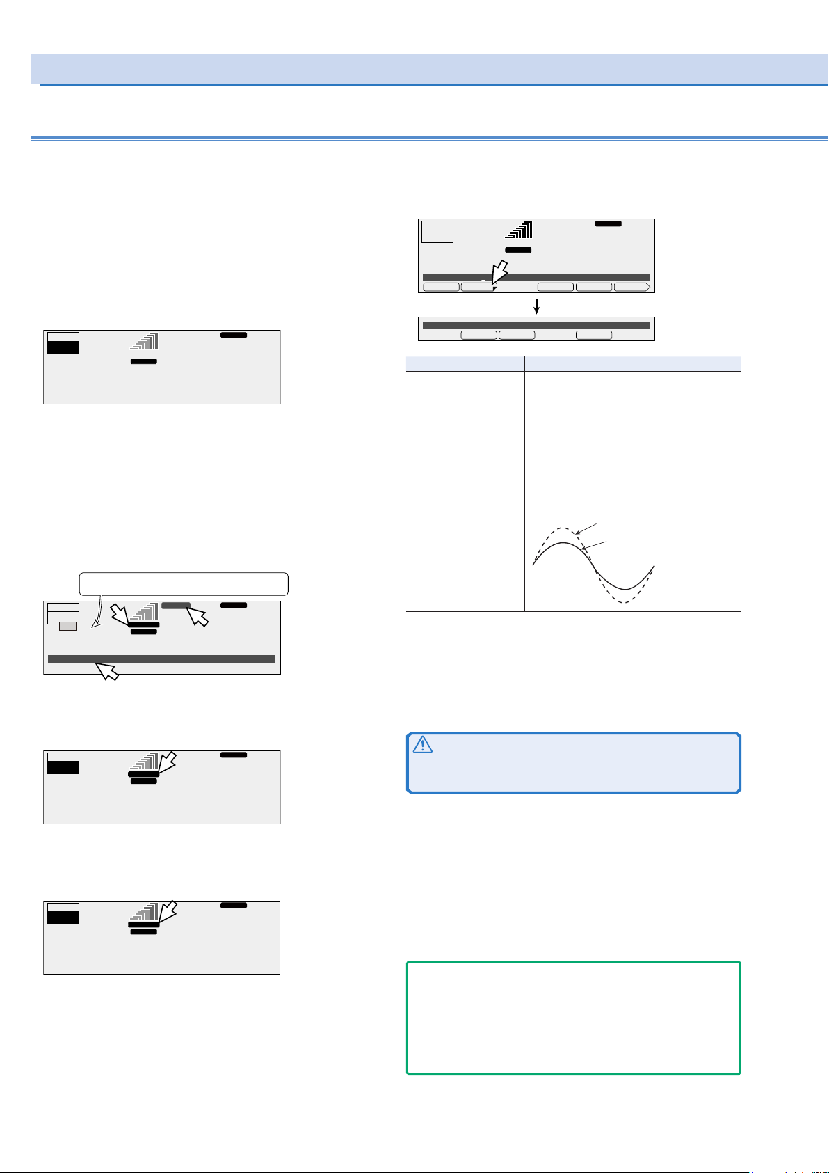
Setting Limits (Cont.)
ACLOAD
DISABLEENABLE
ACLOAD
TRIP TIM
Current limit and peak current limits (Cont.)
Action to perform when the current limit is exceeded
You can set the action to perform (whether the output is turned
off) when the current exceeds the current limit. In AC mode,
you can set the time that elapses before the output is turned off
when the current limit is exceeded.
The current limit function operates on the rms value of the current.
Action: Turn the output off (ENABLE)
•
The limit has not been exceeded
OUTPUT
ON
6.87
A
•
The limit has been exceeded
99.00
RANGE
L
rms rms
In AC mode, the output is turned off after the specified trip
time has elapsed.
In DC mode and AC+DC mode, the output is turned off 1
second after the limit has been exceeded.
There is a delay in the response depending on the aperture
time setting. After the output is turned off, there is a period of
approximately 120 seconds (the “Busy” state) during which
the output cannot be turned on.
Cleared after approximately 120 seconds.
Counts down the time until the indication is cleared.
OUTPUT
OFF
Busy...
80 s
0.01
ALM-06 OVERLOAD
ALARM
99.00
OVERLOAD
RANGE L
pk rms
A
RESP.M
Hz
28.1
RESP.M
ACLOAD
Hz
0.0
V
V
Press I and then TRIP (F2) to select the action to perform when
the limit is exceeded.
OUTPUT
OFF
6.87
ILimit 3.85A
Trip ENABLE
Item Title Description
ENABLE Trip If the current exceeds the current limit for
DISABLE If the current is less than the current limit,
*1. This is calculated as an rms value. The current limit may be exceeded for a
few seconds because of the relationship between the measurement processing time and the voltage resolution. The current may oscillate (increase and
decrease) while it is being controlled.
A
99.00
RANGE
L
rms rms
+IPKLIM 1/2TRIPILIMIT
more than a set amount of time, “OVERLOAD”
lights, the output is turned off, and an alarm
(ALM-06: OVERLOAD) is generated.
“TRIP DIS.” lights.
If a current that is greater than the current limit flows, “OVERLOAD” lights, and the output
voltage is controlled so that the current does
not exceed the current limit.
RESP.M
Hz
28.1
-IPKLIM
Normal operation
During output
voltage control
V
Voltage waveform
*1
Action: Do not turn the output off (DISABLE)
•
The limit has not been exceeded
RESP.M
L
99.00
ACLOAD
Hz
28.1
V
OUTPUT
ON
6.87
•
The limit has been exceeded
TRIP DIS.
RANGE
rms rms
A
The output voltage is controlled so that the current limit is not
exceeded.
RESP.M
L
99.00
ACLOAD
Hz
102.3
V
OUTPUT
ON
50.78
OVERLOAD
RANGE
rms rms
A
If you have selected ENABLE (to turn the output off)
To clear the alarm, press ALM CLR (SHIFT+CLR).
CAUTION
Risk of product malfunction. If an overload occurs, be sure to
remove the cause of the problem, and then press OUTPUT.
If you have selected DISABLE (to not turn the output off)
If you have selected to not turn the output off (DISABLE), you
will not be able to:
Turn soft start on (set the rise time).
Execute power line abnormality simulations.
Execute sequences.
Use the compensation function’s software sensing and regu-
lation adjustment.
- Note -
If the load short-circuits, if an extreme overload occurs, or if the
difference between the output voltage and the output voltage setting during output voltage control is large (the output voltage setting is high), (1) the internal semiconductor protection (OCP) may
be activated and the output voltage waveform may be distorted or
(2) an alarm (ALM-03: OCP) may occur.
34 PCR-LE series
Page 35
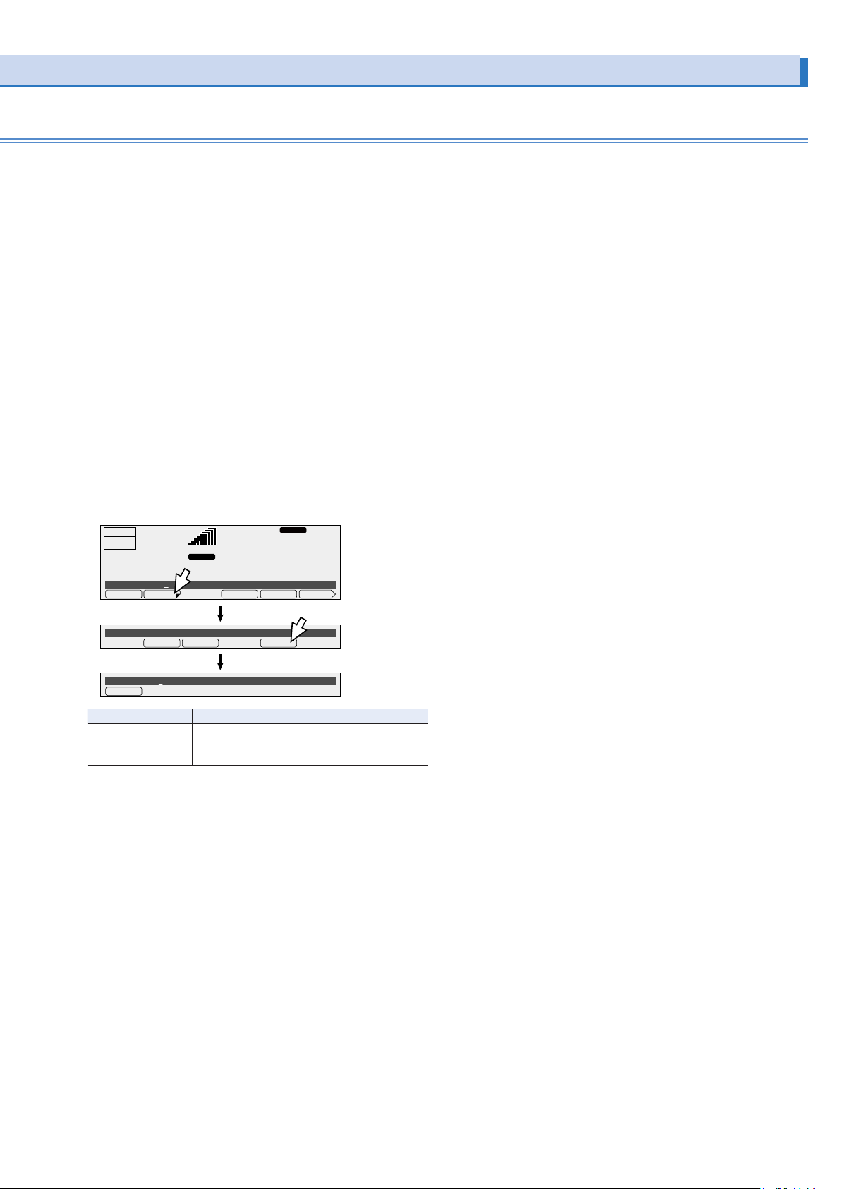
Setting the time (Trip time) that elapses before the output is
ACLOAD
turned off when the current limit is exceeded
In AC mode, you can set the amount of time that elapses after
the current limit is exceeded (the amount of time during which
the current limit is continuously exceeded) before the output is
turned off. This is useful when you don’t want the output to be
turned off due to issues such as inrush current causing shortterm overloads.
If the voltage setting is at or lower than 10 V (L range) or 20 V (H
range), the output will turn off after 3 s even if you set the trip
time to 4 s or longer.
The amount time until the output is turned off may become
large due to the state of the load or the timing of the PCR-LE
Series internal current measurement. There is a delay in the response depending on the aperture time setting.
If the full scale bar of the load level meter continues to be lit,
the temperature inside the PCR-LE is high. If an overload occurs repeatedly, the time until the output is turned off may be
shortened.
Press I, TRIP (F2), and then TRIP TIM (F5) to set the time that
elapses before the output is turned off.
OUTPUT
OFF
6.87
ILimit 3.85A
99.00
RANGE
L
rms rms
A
+IPKLIM 1/2TRIPILIMIT
RESP.M
Hz
28.1
-IPKLIM
V
Trip ENABLE
Trip Time 10s
TRIP TIM
Item Title Description Valid mode
TRIP TIM Trip Time Sets the time that elapses (0 s to
DISABLEENABLE
10 s) before the output is turned off
when the current limit is exceeded
TRIP TIM
AC
PCR-LE series 35
Page 36
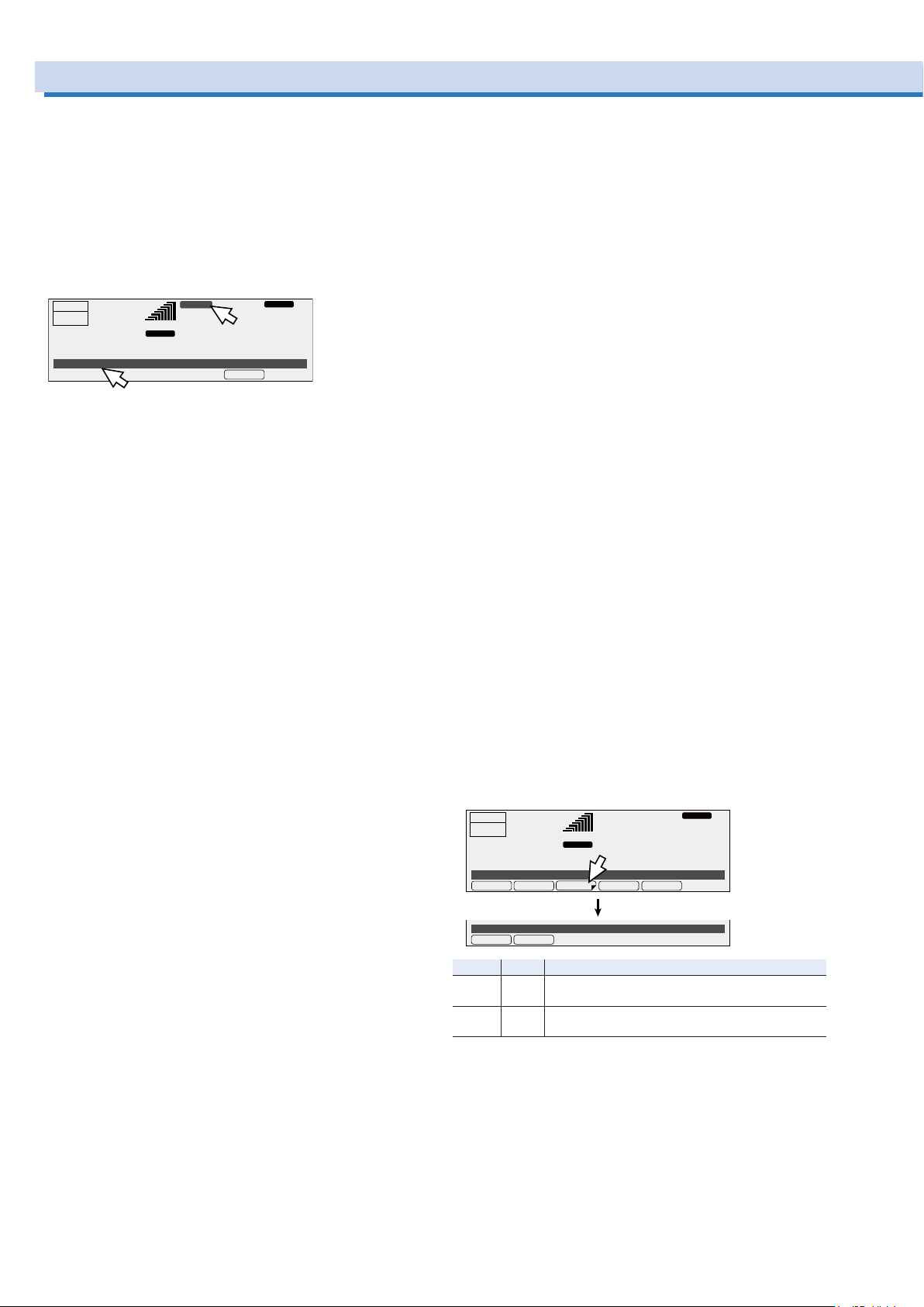
Using Protection Functions
AC+DCLOAD
The PCR-LE Series has the following protection functions.
Input voltage drop protection
Overheat protection (OHP)
Overload protection
Internal semiconductor protection (OCP)
Output undervoltage protection (UVP)
Output overvoltage protection (OVP)
If a protection function is activated, an alarm sounds, “ALARM”
is displayed on the screen, and the output is turned off.
Hz
ALM CHK
RESP.M
V
ACLOAD
OUTPUT
OFF
50.78
ALM-08 UNIT FAIL
During master-slave parallel operation(optional), if an alarm
occurs on one unit, the entire system’s output will be turned off.
Clearing alarms
Press ALM CLR (SHIFT+CLR) to clear the alarm, and then fix
the problem that caused the alarm.
If an alarm still occurs even after you have corrected all the
causes of alarms, the PCR-LE Series may be malfunctioning.
Stop using it immediately, and contact your Kikusui agent or
distributor. Inform the individual that you contact of the alarm
code that is displayed.
Input voltage drop protection
If the input voltage drops lower than the rating, the input voltage drop protection function is activated, and an alarm (AC
INPUT LOW) is generated. Adjust the input voltage so that it is
within the range in the specifications. If the input power supply
wiring is long, use wires that have a large diameter to make the
voltage drops smaller.
Overheat protection (OHP)
If the internal temperature rises to an abnormal level, the overheat protection is activated, and an alarm (ALM-02: OHP) is
generated. Leave the PCR-LE Series on, and wait for approximately 10 minutes.
If the alarm has stopped occurring after 10 minutes, the PCRLE Series may have been installed incorrectly, or the dust filter
may be clogged.
If there are no problems with the installation or the dust filter,
stop using the PCR-LE Series immediately, and contact your
Kikusui agent or distributor to request repairs.
Overload protection
If the output current exceeds the rated current or the current
limit (-> p32), the overload protection is activated, and an
alarm is generated (ALM-06: OVERLOAD).
During reverse power flow, the protection is activated at 30%
of the rated current or the current limit, whichever is less.
You can set how the PCR-LE Series acts when the current limit
is exceeded.
ALARM
99.00
RANGE
L
pk rms
A
102.3
Output undervoltage protection (UVP) and output
overvoltage protection (OVP)
UVP and OVP judgment varies depending on the voltage
mode.
AC mode: Judgment is based on the rms voltage measurements.
DC mode: Judgment is based on the averaged voltage measurements.
AC+DC mode: Judgment is based on both the rms and averaged voltage measurements.
•
Output undervoltage protection (UVP)
If the output voltage drops below the UVP setting and remains there for approximately 1 second, the output undervoltage protection will be activated. An alarm (ALM-07: UVP)
will be generated.
•
Output overvoltage protection (OVP)
If the output voltage exceeds the OVP setting and remains
there for approximately 1 second, the output overvoltage
protection will be activated. An alarm (ALM-00: OVP) will be
generated.
•
Setting UVP and OVP
In AC mode, specify an rms value. In DC mode, specify an
average value.
In AC+DC mode, specify an rms value. To set an average
value, change to DC mode, set the average value, and then
return to AC+DC mode.
For single-phase three-wire output and three-phase output
(optional), set the limits using phase voltages.
During single-phase three-wire output and three-phase output (optional), set the limits using phase voltages.
To set the OVP value, press V, PROTECT (F3), and then OVP
(F1).
To set the UVP value, press V, PROTECT (F3), and then UVP
(F2).
If PROTECT(F3) does not appear, hold down F6 until it appears.
Hz
28.1
VMINVMAXDCVOLTACVOLT PROTECT
RESP.M
V
OUTPUT
OFF
6.87
ACVolt 7.5V
OVP 335.5V
Item Title Description
OVP OVP Sets the OVP value (0.0 V to 474.1 V in AC mode and
UVP UVP Sets the UVP value (0.0 V to 474.1 V in AC mode and
A
UVPOVP
AC+DC mode, -474.1 V to 474.1 V in DC mode)
AC+DC mode, -474.1 V to 474.1 V in DC mode)
58.00
RANGE
L
rns rms
36 PCR-LE series
Page 37
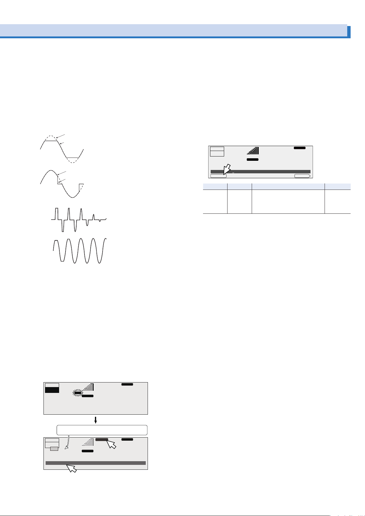
Voltage waveform
Current waveform
Voltage waveform
semiconductor protection has been activated.
ACLOAD
ACLOAD
Internal semiconductor protection (OCP)
This protection function protects the internal semiconductors
of the PCR-LE Series. The internal semiconductor protection
function will not be activated if you follow the PCR-LE Series
usage guidelines outlined in the specifications. If a temporary
overcurrent - such as an inrush current - occurs, the internal
semiconductor protection function will be activated. If the internal semiconductor protection function remains activated for a
set amount of time, an alarm (ALM-03: OCP) will be generated.
If the internal semiconductor protection function is activated,
the output voltage waveform will be distorted.
Normal operation
The internal semiconductor
protection has been activated.
Voltage waveform
Normal operation
The internal semiconductor
protection has been activated.
Example of the waveforms when the internal
In AC mode, you can set the time that elapses after the internal
semiconductor protection function is activated before an alarm
is generated. An alarm will only be generated if the internal
semiconductor protection function circuit remains activated
continually for the specified length of time. This is useful when
you don’t want alarms to be generated due to short-term overloads such as those caused by inrush current.
In DC mode and AC+DC mode, an alarm is generated 1 second after the internal semiconductor protection is activated.
“OCP” is displayed when the internal semiconductor protection
is activated.
After the alarm is generated, there is a period of approximately
120 seconds (the “Busy” state) during which the output cannot
be turned on.
displayed. The time until the “Busy
The time until the “Busy
” indication is cleared is dis-
” indicat
ion is cleared is
played.
OUTPUT
ON
50.78
OCP
A
99.00
RANGE L
rms rms
RESP.M
Hz
102.3
V
Setting the time that elapses before an alarm is generated
In AC mode, you can set the time that elapses after the internal
semiconductor protection has been activated (the amount of
time during which the internal semiconductor protection is continually activated) before an alarm is generated.
The amount time that elapses before an alarm is generated
may increase depending on the overload state.
Even if an alarm is not generated, the output voltage waveform
will be distorted because the internal semiconductor protection
circuit has been activated.
Press I, 1/2 (F6), and then OCP TIM (F1) to set the time that
elapses before an alarm is generated.
Hz
28.1
RESP.M
V
2/2
AC
OUTPUT
OFF
6.87
OCP Time 3s
OCP TIM
Item Title Description Valid mode
OCPTIM OCPTIME Sets the time that elapses after the
A
99.00
RANGE
L
rms rms
internal semiconductor protection
function is activated before an
alarm is generated (1 s to 3 s)
Dealing with alarms
If an alarm has occurred, follow the remedies shown below,
wait for at least 1 minute, and then resume the operation.
If you remove the problem that caused the internal semiconductor protection to be activated, the alarm will be cleared
automatically. While the internal semiconductor protection is
activated, pressing ALM CLR (SHIFT+CLR) will not clear the
alarm.
•
Linear load
If the current has exceeded the rated current, decrease the
load.
If the power factor is low (the phase is lagging), use a phaseadvancing capacitor or similar device to increase the power
factor.
If the power factor is low (the phase is leading), connect
a dummy resistance in parallel to the load to increase the
power factor.
•
Capacitor-input rectier load
Decrease the peak current.
•
Load that draw an inrush current
Decrease the inrush current.
Configure soft starts (the voltage rise time).
PCR-LE series 37
Cleared after approximately 120 seconds.
Counts down the time until the indication is cleared.
RESP.M
ACLOAD
OUTPUT
OFF
Busy...
80 s
0.01
ALM-03 OCP
If the internal semiconductor protection is activated repeatedly,
the PCR-LE Series may malfunction.
ALARM
99.00
RANGE L
pk rms
A
Hz
0.0
V
Page 38
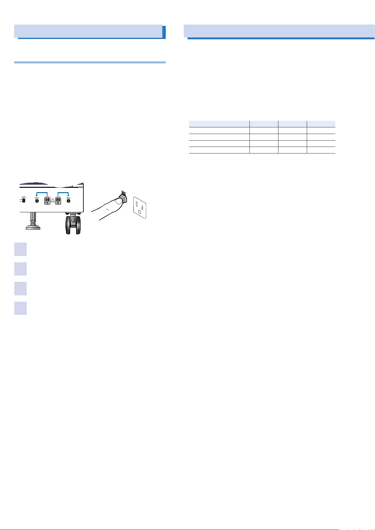
Using Protection Functions (Cont.)
What to do if the breaker trips
The PCR500LE and PCR1000LE do not have a breaker.
On the PCR2000LE, PCR3000LE, PCR4000LE, PCR6000LE,
and PCR9000LE, if an output current of 10 A or greater flows
from one of the outlets on the front panel, the breaker next to
the outlet may trip, which will cut off the outlet’s output. If the
breaker trips, the red button (the breaker button) will pop out.
The total output current that can be generated from the two
outlets and the OUTPUT terminal block on the rear panel is the
rated output current. If the rated value is exceeded, the overload protection function is activated.
For example, on the PCR4000LE, when the output voltage is
100 V (the 100 V range), the load power factor is 1, and the
output frequency is 50 Hz, if an output current of 10 A is flowing
from each outlet, the maximum output current that can be generated from the OUTPUT terminal block is (40 A - 10 A - 10 A =)
20 A.
Using Memory
You can store data to the PCR-LE’s internal memory and save
data to a USB memory device.
•
Internal memory
This is useful when you are testing drastic changes in voltage or frequency.
You can store up to 99 sets of settings (the memory numbers
are 0 to 99, but “0” is only for recalling settings).
The following settings can be stored to and recalled from
memory.
AC DC AC+DC
Frequency Ye s No Yes
AC voltage Yes No Yes
DC voltage No Yes Ye s
Waveform bank number Yes No Yes
•
USB memory device
The internal memory, panel settings, power line abnormality
simulations, sequence data, and the data of one waveform
bank can be saved.
Turn the POWER switch off.
1
Press the breaker button in.
2
Adjust the load so that the output current is less
3
than or equal to 10 A.
Turn the POWER switch on.
4
38 PCR-LE series
Page 39
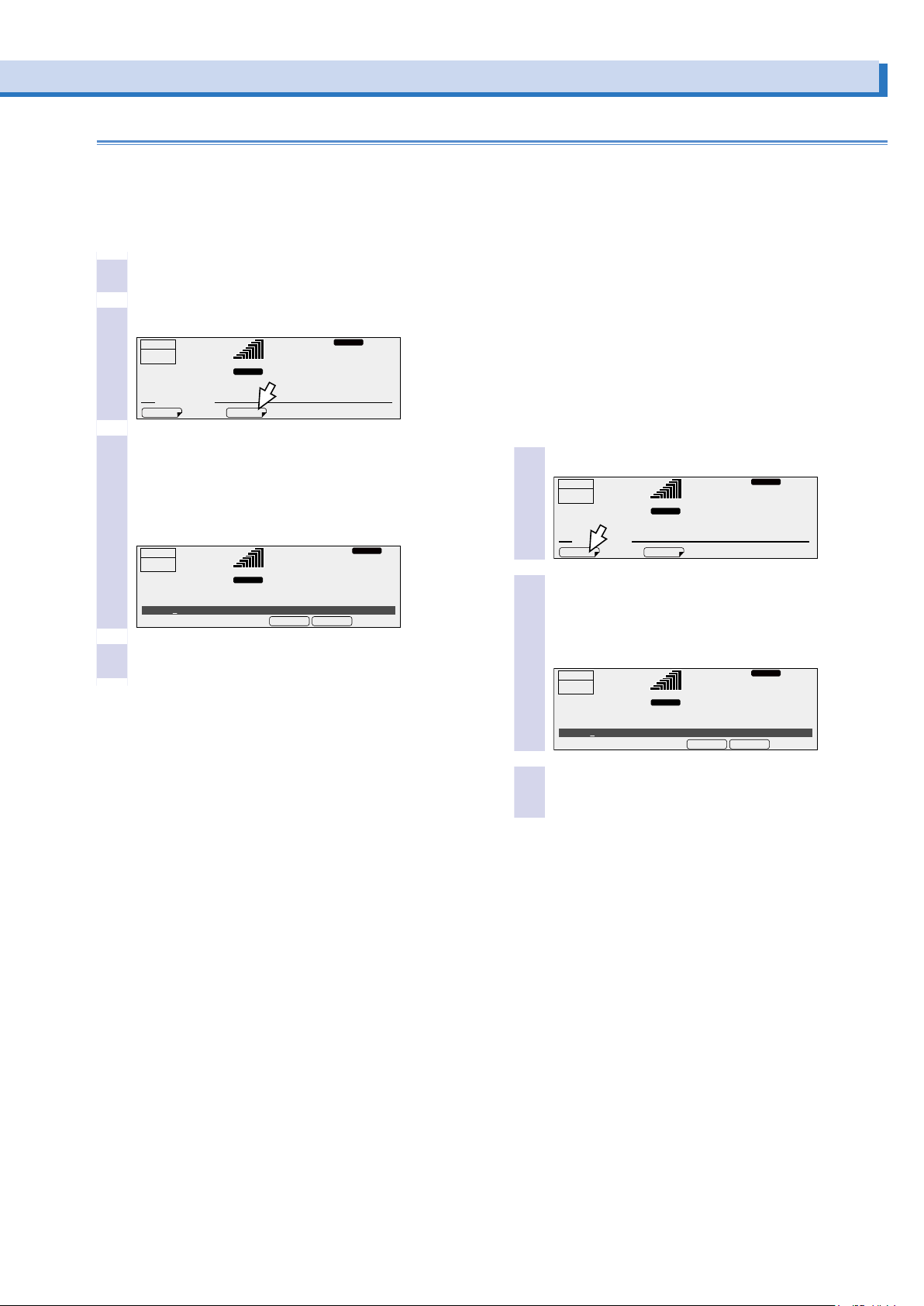
Using internal memory
ACLOAD
CANCELSTORE
ACLOAD
CANCELRECALL
The frequency, AC voltage, DC voltage, and waveform bank number can be stored to and recalled from the internal memory.
During single-phase, three-wire output and three-phase output (optional), phase voltages are stored. Line voltages are calculated from
phase voltages.
Storing data to the internal memory
Set up the conguration that you want to store.
1
Press MEMORY, STR No (F3).
2
OUTPUT
OFF
6.87
MEMORY. MEMU
Use the numeric keypad or the rotary knob to se-
3
lect the memory number where you want to store
the conguration.
The settings that will be stored (frequency, AC voltage, DC
voltage, and waveform bank number) are displayed in the
entry area.
OUTPUT
OFF
6.87
Store 1:
50.00Hz, 28.0Vac, WB 0
Press STORE (F4) to store the settings.
4
The present settings are stored.
A
STR NoRCL No
A
50.00
RANGE
L
rms rms
50.00
RANGE L
rms rms
RESP.M
Hz
28.1
ACLOAD
Hz
28.1
V
RESP.M
V
Recalling settings from memory
If the frequency that you recall is lower than the present frequency lower limit, the frequency will be set to the lower limit.
If the frequency that you recall is higher than the present frequency upper limit, the frequency will be set to the upper limit.
If (1) the voltage that you recall is lower than the voltage lower
limit or is higher than the voltage upper limit, (2) the voltage
that you recall is outside of the set range when the L range
has been selected, or (3) the peak voltage in AC+DC mode is
outside of the following ranges: -431 V to 431 V (H range) or
-215.5 V to 215.5 V (L range), the output voltage will be set to
0 V.
Press MEMORY and then RCL No (F1).
1
OUTPUT
OFF
6.87
MEMORY. MEMU
Use the numeric keypad or the rotary knob to se-
2
lect the memory number that you want to recall.
The settings that will be recalled (frequency, AC voltage,
DC voltage, and waveform bank number) are displayed in
the entry area.
OUTPUT
OFF
6.87
Recall 1:
50.00Hz, 28.0Vac, WB 0
A
STR NoRCL No
A
50.00
RANGE
L
rms rms
50.00
RANGE L
rms rms
Hz
28.1
ACLOAD
Hz
28.1
RESP.M
RESP.M
V
V
Press RECALL (F4) to recall the settings from
3
memory.
The new values will be applied.
PCR-LE series 39
Page 40

ACLOAD
Using Memory (Cont.)
Using USB memory devices
The data of one waveform bank, internal memory (entries number 1 to 99), panel settings, power line abnormality simulations,
and sequence data can be saved to a USB memory device.
Data cannot be saved to or recalled from a USB memory device while power line abnormality simulations or sequences are
being performed.
You cannot use a USB memory device that has a capacity
greater than 16 GB.
Use a PC to format the USB memory device (into FAT32 format).
Some USB memory devices may not operate correctly.
Setting the date and time
The date and time are used in the timestamps of files saved to
USB memory devices. If the product is left turned off for two to
three weeks, the date and time settings will be cleared.
Press CONFIG (SHIFT+OPR MODE), 1/2 (F6), and
1
then DATE TIM (F1).
OUTPUT
OFF
6.87
CONFIG. MEMU
DATE TIM
Use the left arrow and right arrow function keys
2
to move the cursor to the setting that you want to
A
SURGE S
99.00
RANGE
L
rms rms
RESP.M
Hz
28.1
VMINVMAXDCVOLTACVOLT PROTECT
V
2/2
change (year, month, day, hour, or minute), and
then use the rotary knob to set the value.
You cannot use the numeric keypad. You cannot set the
seconds.
RESP.M
L
99.00
ACLOAD
Hz
28.1
VMINVMAXDCVOLTACVOLT PROTECT
CANCELAPPLY
V
OUTPUT
OFF
Press this key to move the cursor to the item on the left.
▲
Press this key to move the cursor to the item on the right.
6.87
Date/Time 2011/04/01 12:00:00
▼
RANGE
▼
rms rms
A
▼
Folders where the les are saved and le names
The following folders are created on the USB memory device.
The files—whose names are “folder name + a three-digit number (001 to 999).txt”—are then saved in these folders.
You cannot use the PCR-LE Series to delete or rename files.
Use a PC to perform these operations.
Use alphanumeric characters for the file names. You cannot
use forward slashes, back slashes, asterisks, question marks,
double quotation marks, angled brackets (left or right), or vertical bars.
Do not store more than 100 files in each folder.
Saved contents Created folder File name
Internal memory MEM MEMxxx.txt
Panel settings SET SETxxx.txt
Power line abnormality simulations SIM SIMxxx.txt
Sequence data SEQ SEQxxx.txt
Waveform bank contents WAVE WAVExxx.txt
*1. The “xxx” in the file name is a sequence number (001 to 999) that is automati-
cally appended to the file name.
*1
Press APPLY (F4) to conrm the date and time.
3
The new values will be applied.
If you specify a day that does not exist (for example, February 30), the settings will be changed to the first day of
the following month.
40 PCR-LE series
Page 41

Saving data to USB memory devices
ACLOAD
SAVELOAD
ACLOAD
WAVE
ACLOAD
Set up the conguration that you want to save.
1
Connect a USB memory device to the USB port
2
on the front panel.
Press OTHERS (SHIFT+MEMORY), 1/3 (F6), FILE
3
(F5), and then SAVE (F3).
OUTPUT
OFF
6.87
COMPEN
A
RESP
OTHER. MEMU
OTHER : FILE
Select the item that you want to save.
4
Item Description
MEM Internal memory
SET Panel settings
SIM Power line abnormality simulations
SEQ Sequence data
WAVE Waveform bank contents
99.00
RANGE
L
rms rms
PON OUTPVCC
RESP.M
Hz
28.1
FILE
V
2/3
Press SAVE (F4) to save the settings.
6
Do not remove the USB memory device until “File was
saved” disappears.
OUTPUT
OFF
6.87
SET
A
SIM
OTHER : FILE : SAVE
Remove the USB memory device from the USB
7
port.
99.00
RANGE
L
rms rms
SEQMEM
RESP.M
Hz
28.1
File was saved
Disappears when
saving is finished
V
The name of the file that the data will be saved to is displayed in the entry area. When you are saving a waveform
bank, the number of the waveform bank that you are saving
and the file name are displayed.
You cannot use the numeric keypad.
OUTPUT
OFF
6.87
SET
A
SIM
OTHER : FILE : SAVE
WAVE以外(シーケンスの例)
File name: SEQ001.txt
WAVE
WB No. 1 File name: WAVE001.txt
To save a waveform bank, rst select the wave-
5
form bank item, and then use the rotary knob to
99.00
RANGE
L
rms rms
SEQMEM
RESP.M
Hz
28.1
WAVE
CANCELSAVE
CANCELSAVE
V
select the number of the waveform bank that you
want to save.
During single-phase, three-wire output or three-phase output (optional), if you are saving a user-defined waveform,
select the phase that you want to save using PHASE SEL
(F3).
PCR-LE series 41
Page 42
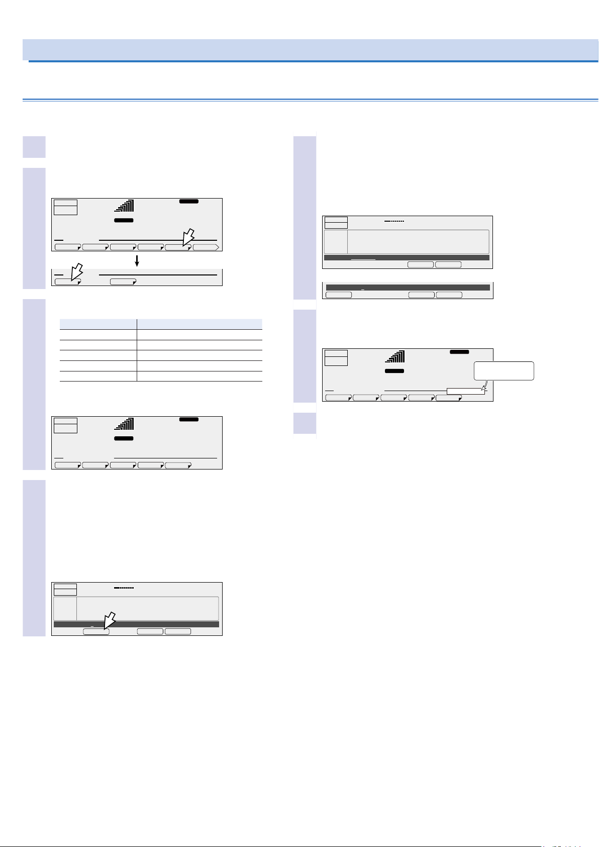
SET
WAVE
SIM
SEQMEM
LOAD
10.00Hz
CANCELLOAD
A value other than WAVE (panel settings in this example)
SET
WAVE
SIM
SEQMEM
ACLOAD
Using Memory (Cont.)
Using USB memory devices (Cont.)
Recalling settings from a USB memory device
Connect a USB memory device to the USB port
1
on the front panel.
Press OTHERS (SHIFT+MEMORY), 1/3 (F6), FILE
2
(F5), and then LOAD (F1).
RESP.M
99.00
L
PON OUTP
ACLOAD
Hz
28.1
FILE
V
2/3
OUTPUT
OFF
6.87
OTHER. MEMU
COMPEN
OTHER : FILE
Select the item that you want to recall.
3
Item Description
MEM Internal memory
SET Panel settings
SIM Power line abnormality simulations
SEQ Sequence data
WAVE Waveform bank contents
RANGE
rms rms
A
RESPVCC
SAVELOAD
The name of the file saved to the USB memory device is
displayed.
RESP.M
L
99.00
ACLOAD
Hz
28.1
V
OUTPUT
OFF
6.87
OTHER : FILE : LOAD
RANGE
rms rms
A
Use the rotary knob to select the file that you
5
want to recall.
When you are recalling a waveform bank, press WB No.
(F1) to change the number of the waveform bank that the
recalled waveform bank will be saved in. You cannot use
the numeric keypad.
OUTPUT
OFF
FILES
File name: SET001.txt
WAVE
WB No. 1 File name: WAVE001.txt
WB No.
Press LOAD (F4) to recall the le.
6
Do not remove the USB memory device until “File was
LOAD
0.00
SET001.txt 2011/05/25 16:23
SET002.txt 2011/05/27 10:11
SET003.txt 2011/05/27 12:05
SET004.txt 2011/06/01 20:05
A rms
10.00Hz
0.0
CANCELLOAD
V rms
loaded” disappears.
OUTPUT
OFF
6.87
OTHER : FILE : LOAD
Remove the USB memory device from the USB
7
port.
A
99.00
RANGE
L
rms rms
RESP.M
Hz
28.1
File was loaded
Disappears when
loading is finished
V
To recall a waveform bank, use the rotary knob
4
to specify the number of the waveform bank that
the recalled waveform bank will be saved in, and
then press FILE SEL (F2).
You cannot use the numeric keypad.
During single-phase, three-wire output or three-phase output (optional), if you are recalling a user-defined waveform,
select the phase that you want to recall using PHASE SEL
(F3).
OUTPUT
OFF
FILES
WB No. 1 File name: WAVE001.txt
0.00
WAVE001.txt 2011/05/25 16:23
WAVE002.txt 2011/05/27 10:11
WAVE003.txt 2011/05/27 12:05
WAVE004.txt 2011/06/01 20:05
FILE SEL
A rms
0.0
CANCELLOAD
V rms
42 PCR-LE series
Page 43

Error messages
If there is a problem with the USB memory device, an error will
occur. Error messages are displayed when errors occur.
Error message Description
Data out of range. (Line = the line
number)
Disk access error. (Error code) A USB memory device read or
Disk error. (Error code; line = the
line number)
Disk full. There is no free space on the USB
Disk mount error. The mounting of the USB memory
File not found. The file could not be found.
Illegal parameter. (Line = the line
number)
No disk. The USB memory device is not
Not supported. (Line = the line
number)
Path not found. The path (folder) could not be
Settings conflict. (Line = the line
number)
Syntax error. (Line = the line number)
A setting is outside of its range.
write error occurred.
An error not listed here occurred.
memory device.
device failed.
A parameter was illegal.
connected.
The read operation is not supported.
found.
The PCR-LE Series is in a condition in which the function key
cannot be used.
The delimiter character could not
be found.
PCR-LE series 43
Page 44

44 PCR-LE series
Page 45

This chapter explains the advanced operations of the PCR-LE Series.
AC
LOAD
ACLOAD
L
N
L
N
U
VW
R
L
N
U
V
W
R
L
N
U
W
Using the Synchronization Function
- Advanced -
The synchronization function synchronizes the frequency and
phase of the PCR-LE Series output voltage with a 50 Hz or 60 Hz
input power supply. This is valid in AC mode and AC+DC mode.
This is useful in situations such as when the display of an external measuring instrument is not stable.
Setting the synchronization delay phase angle enables you to
manage the synchronization phase of the input voltage on the
three-phase input model (PCR9000LE) with a high degree of
precision.
Turning the synchronization function on disables the frequency
limit function.
Turning the synchronization function on and off
If the input voltage frequency is outside of the rated range or
if the input power supply voltage distortion and the noise are
extremely large, synchronization is not possible. In these situations, “SYNC NG” is displayed.
Press SYNC (SHIFT+9) to turn the synchronization function on
and off.
OUTPUT
OFF
6.87
Sync ON
Item Title Description Valid
ON Sync The synchronization function is enabled.
OFF The synchronization function is disabled.
Setting the synchronization delay phase angle
“SYNC” or “SYNC+P” blinks until synchronization
is established.
After a few seconds, the frequency and the phase
are synchronized, “SYNC” or “SYNC+P” lights,
and the synchronized frequency is displayed.
SYNC
RANGE L
rms rms
A
DELAY
OFFON
RESP.M
50.--
Hz
When the synchronization delay phase
angle is set to 0 deg, SYNC lights.
28.1
When the synchronization delay phase
angle is set to a value other than 0 deg,
SYNC+P lights.
V
modes
AC and
AC+DC
Press SYNC (SHIFT+9) and then DELAY (F4) to set the value.
50.00
28.1
RESP.M
Hz
V
OUTPUT
OFF
6.87
Sync delay deg 0deg
RANGE L
rms rms
A
The frequency that is used when the synchroniza-
tion function is cleared
If the frequency when you are using the synchronization function is within the frequency limits, the frequency is set to the 50
Hz or 60 Hz, whichever the PCR-LE Series was synchronized
to.
If the frequency when you are using the synchronization function is outside the frequency limits, the frequency limit function
will be activated.
If the frequency when you are using the synchronization function is lower than the lower limit, the frequency is set to the
lower limit.
If the frequency when you are using the synchronization function is higher than the upper limit, the frequency is set to the
upper limit.
Phase
The figure below shows the phase synchronization behavior for
different input-wiring and output configurations.
Input wiring
Single-phase input
ST
Three-phase, three-wire input
PCR6000LE 200V
PCR9000LE 200 V
N
T
Three-phase, four-wire input
PCR6000LE 200 V
PCR9000LE 400 V
S
Single-phase output
Single-phase, three-
wire output
In-phase with the
input
In-phase with input
V
R-S
In-phase with input
V
R-N
Three-phase output
(Optional)
N
V
and V
and V
are in phase.
L-N
N
are in phase.
R-S
N
V
U-N
V
U-N
In-phase with the input
Item Title Description Valid modes
DELAY Sync delay
PCR-LE series 45
deg
Sets the synchronization delay
phase angle (0 deg to 359 deg)
AC and
AC+DC
Page 46

Using the Voltage compensation Function
The compensation function compensates for voltage drops in the load cables when the load is connected to the PCR-LE Series over a
long distance. The PCR-LE Series has three types of compensation functions: soft sensing, hard sensing, and regulation adjustment.
Use the different compensation functions depending on how you need to use the PCR-LE Series.
During single-phase, three-wire output and three-phase output (optional), regulation adjustment is invalid.
WARNING
Risk of electric shock.
• Before you connect the load or the sensing cables,
turn the POWER switch off, and then remove the power plug from the outlet or turn off the switchboard.
• Firmly attach the terminal box cover.
•
Hard sensing
Connect the PCR-LE’s internal output voltage compensation
point directly across the load. Because compensation is performed in real time, the output voltage can be stabilized at a
high speed.
Because the impedance (the combination of the resistance
and the inductance) of the power line across the load will be
included in the compensation circuit, the power circuit’s stability decreases. The PCR-LE Series operations may become
unstable (for example, it may oscillate) depending on the
wiring and the load type. If the operations become unstable,
use soft sensing.
It is recommended that you use soft sensing if you are using
a load that does not require a fast output voltage response
speed.
You cannot use hard sensing in the following situations.
When the output is on
When you are setting the output impedance (ON)
When you have selected the normal response speed (ME-
DIUM) or the fast response speed (FAST).
•
Soft sensing
The voltage of the sensing point is measured by the PCR-LE
Series measurement functions, and any insufficiencies in the
voltage are automatically compensated for. The performance
of the PCR-LE Series such as the stability of the voltage, output voltage response to sudden changes in the load current,
and waveform quality (distortion ratio) is lower than that available during normal operation.
Even in DC mode, the performance is lower than that available during remote sensing of a normal DC power supply.
The maximum voltage that soft sensing can compensate is
“the PCR-LE Series’ output voltage ±10 %.” The maximum
output voltage during compensation is limited by the rated
voltage of the PCR-LE Series.
If the frequency is less than 40 Hz, soft sensing is disabled.
You cannot use soft sensing in the following situations.
When the output is on
When in AC+DC mode
When you are setting the output impedance (ON)
When you have configured the PCR-LE Series so that it
does not turn output off when the current limit is exceeded
(DISABLE)
When you have specified the waveform bank
When power line abnormality simulations are being per-
formed
When sequences are being performed
When soft start is on.
•
Regulation adjustment
This function calculates the voltage drops that are caused by
the output current and increases the output voltage just by
the calculated voltage drops.
Use this function when there is a great distance between the
PCR-LE Series and the load and you want to stabilize the
voltage across the load. This function does not require you
to connect the sensing cables that the hard sensing and soft
sensing functions require.
The performance of the stabilization accuracy, distortion
ratio, and response speed of the voltage is lower than the
normal performance of the PCR-LE Series. Depending on
how you are using the PCR-LE Series, you may not be able
to use this function. Check the operation that you will perform
before you use the regulation adjustment function.
The maximum voltage that regulation adjustment can compensate is “the PCR-LE Series’ output voltage + 10 %.” The
maximum output voltage during compensation is limited by
the rated voltage of the PCR-LE Series. If the output current
is 10 % or less of the maximum rated current, the voltage is
not compensated.
You cannot use regulation adjustment in the following situations.
When the output is on
When in AC+DC mode, in DC mode
When you are setting the output impedance (ON)
When you have configured the PCR-LE Series so that it
does not turn output off when the current limit is exceeded
(DISABLE)
When you have specified the waveform bank
When power line abnormality simulations are being per-
formed
When sequences are being performed
When soft start is on.
46 PCR-LE series
Page 47
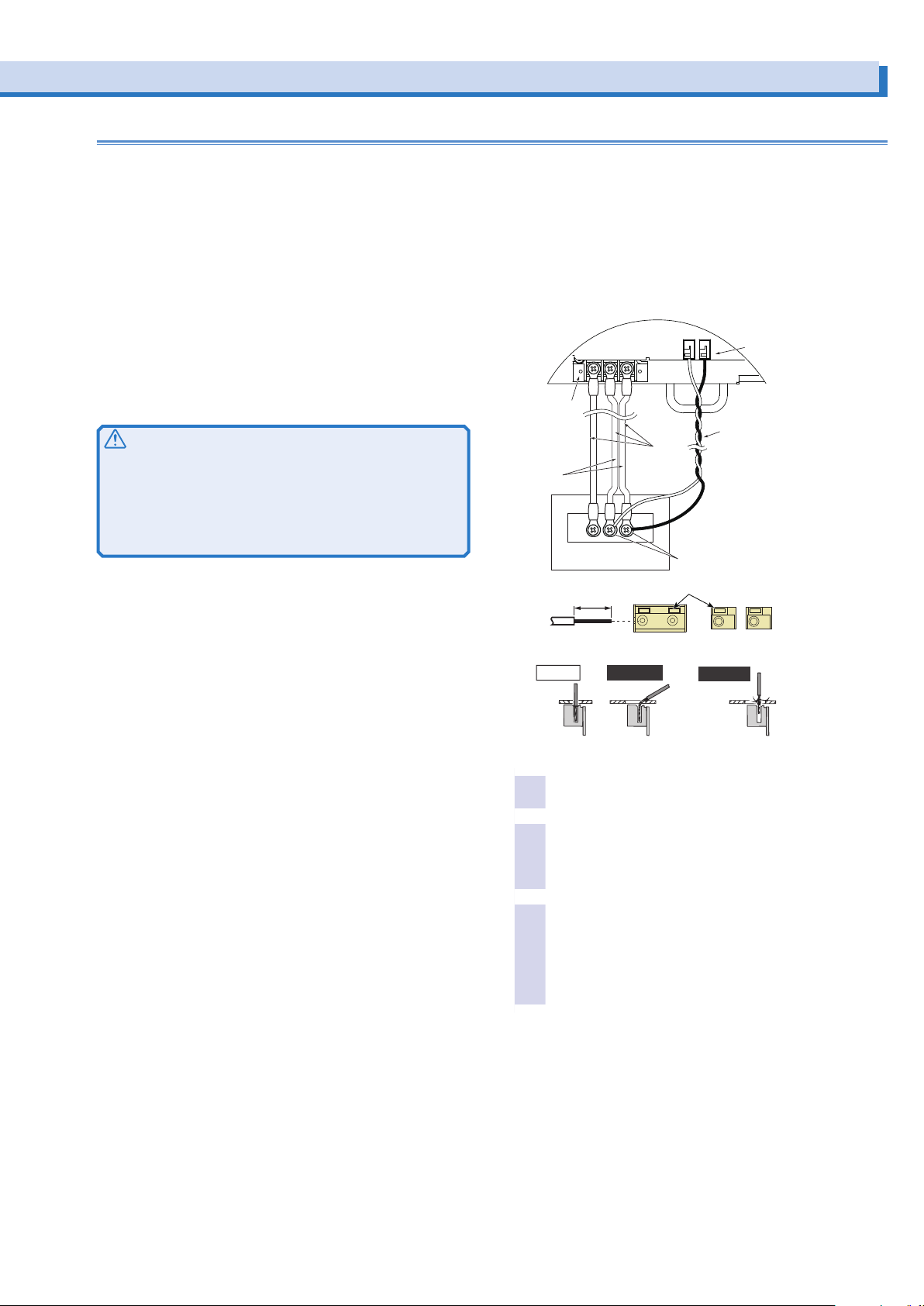
Wiring the hard sensing and soft sensing functions
OUTPUT terminal block and SENSING terminal block
While pressing here with a screwdriver, insert the wire.
the chassis.
Twist the load wires (L and N), and connect between the output
terminal and load with the shortest wires possible. If you cannot
twist the wires, we recommend that you run the wires alongside
each other and tie them together at several points with cable
ties.
The sensing feature can compensate up to 1.5 V for a single
line. Select a load cable that has sufficient current capacity to
prevent the voltage drop in the cable from exceeding the compensation voltage.
As the PCR-LE Series output voltage becomes small, so too
does the detected voltage. If the PCR-LE Series output voltage is small, reduce the voltage drops in the cables by using
cables that have large diameters to wire the load, connecting
the load so that the cables are as short as possible, and taking
other similar precautions.
CAUTION
Risk of damage to the product and the load. If the sensing
cables become disconnected or the polarities are incorrect,
an overvoltage will be generated in the output. The protection
function will be activated and the output will be turned off, but
an overvoltage will be generated for the several hundreds of
milliseconds before the protection function is activated.
Pull out the terminal block tray, and then connect the sensing
cables.
Use AWG22 to AWG16 cables when connecting to the sensing
terminals. Strip approximately 10 mm of coating from the end of
the cables.
Match the N and L of the OUTPUT terminal block and N and L
of the SENSING terminal block.
(The shapes of the terminal blocks vary depending on the model.)
OUTPUT
terminal
block
Short and
Twist/
Run parallel
Load
STRIP-GAUGE
G N L
G N L
(INPUT)
10mm
N L
Load cables
Sensing points
(locations that stabilize
the voltage)
SENSING terminal block
Sensing
cables
The shapes of the terminal blocks
vary depending on the model.
Correct
Check that the POWER switch is turned off.
1
Check that the load’s power switch is off.
2
If you cannot turn the load off, install a dedicated terminal
block for sensing. Do not connect the load to this dedicated
terminal block for sensing.
Connect the N SENSING terminal to the N termi-
3
nal on the DUT using sensing cables. In the same
Incorrect
Incorrect
The stripped
wire is touching
The wire strands
are touching the
chassis.
way, connect the L SENSING terminal to the L terminal on the DUT.
Connect the wiring so that the product is as close to the
load as possible.
PCR-LE series 47
Page 48
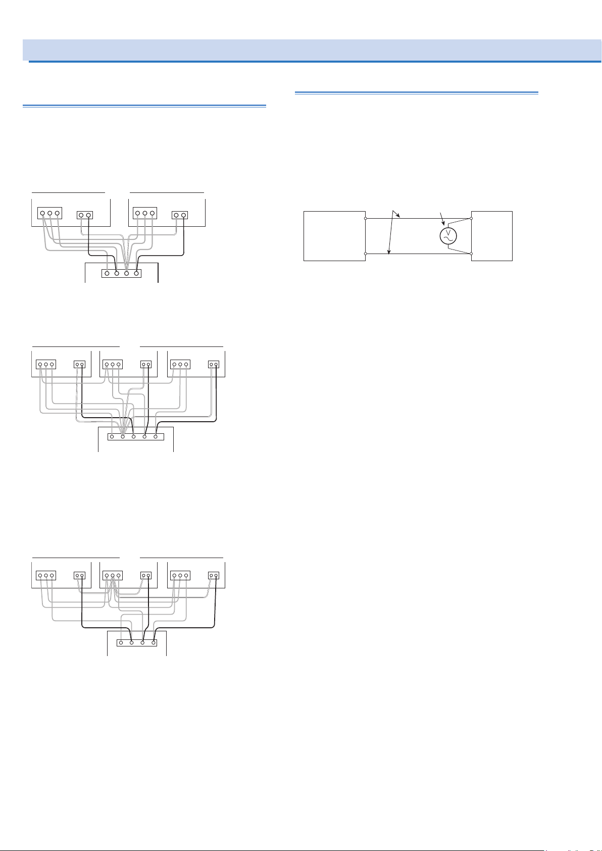
PCR–LE
L1L2 NG
PCR–LE
PCR–LE
Load cables AC voltmeter
Using the Voltage compensation Function (Cont.)
Wiring the hard sensing and soft sensing
functions (Cont.)
Wiring for single-phase three-wire output or three-
phase output (optional)
• Single-phasethree-wireoutput
Connecttheoutput wires ofeachphase (L andN)to
theload(sensingpoint).
OUTPUT
GNL
SENSING
NL
• Three-phaseoutput(Three-phasefour-wire)
Connecttheoutput wires ofeachphase (L andN)to
theload(sensingpoint).
OUTPUT
GNL
SENSING
NL
OUTPUT
GNL
OUTPUT
GNL
SENSING
NL
SENSING
Load
NL
OUTPUT
GNL
U phaseV phase
SENSING
NL
U phaseV phaseW phase
Wiring the regulation adjustment function
After you finish connecting the load, turn the output on. Then,
set the output voltage to the voltage that is required across
the load. Because of voltage drops in the load wiring, the voltage across the load is lower than the voltage generated by
the PCR-LE Series. Use a voltmeter (or other instrument that
enables you to measure voltage) to check whether the voltage
across the load is the required voltage.
The maximum voltage that regulation adjustment can compensate is “the PCR-LE Series’ output voltage + 10 %.”
L
PCR-LE
N
Load
G
(S)U(R)
(T)
V
N W
Load
• Three-phaseoutput(Three-phasethree-wire)
Thestabilityofthree-phase three-wire outputvoltage
decreasesforunbalancedloads. Unstable operation
mayresultwithhardsensing.
Maketheconnection between thePCR-LEseriesN
OUTPUTterminaland N SENSINGterminalasshort as
possible.ConnectallNterminalstothecenterPCR-LE.
OUTPUT
GNL
SENSING
Short
NL
OUTPUT
GNL
NL
V
OUTPUT
GNL
Load
SENSING
NL
U phaseV phaseW phase
Short
SENSING
W
G
(S)U(R)
(T)
48 PCR-LE series
Page 49
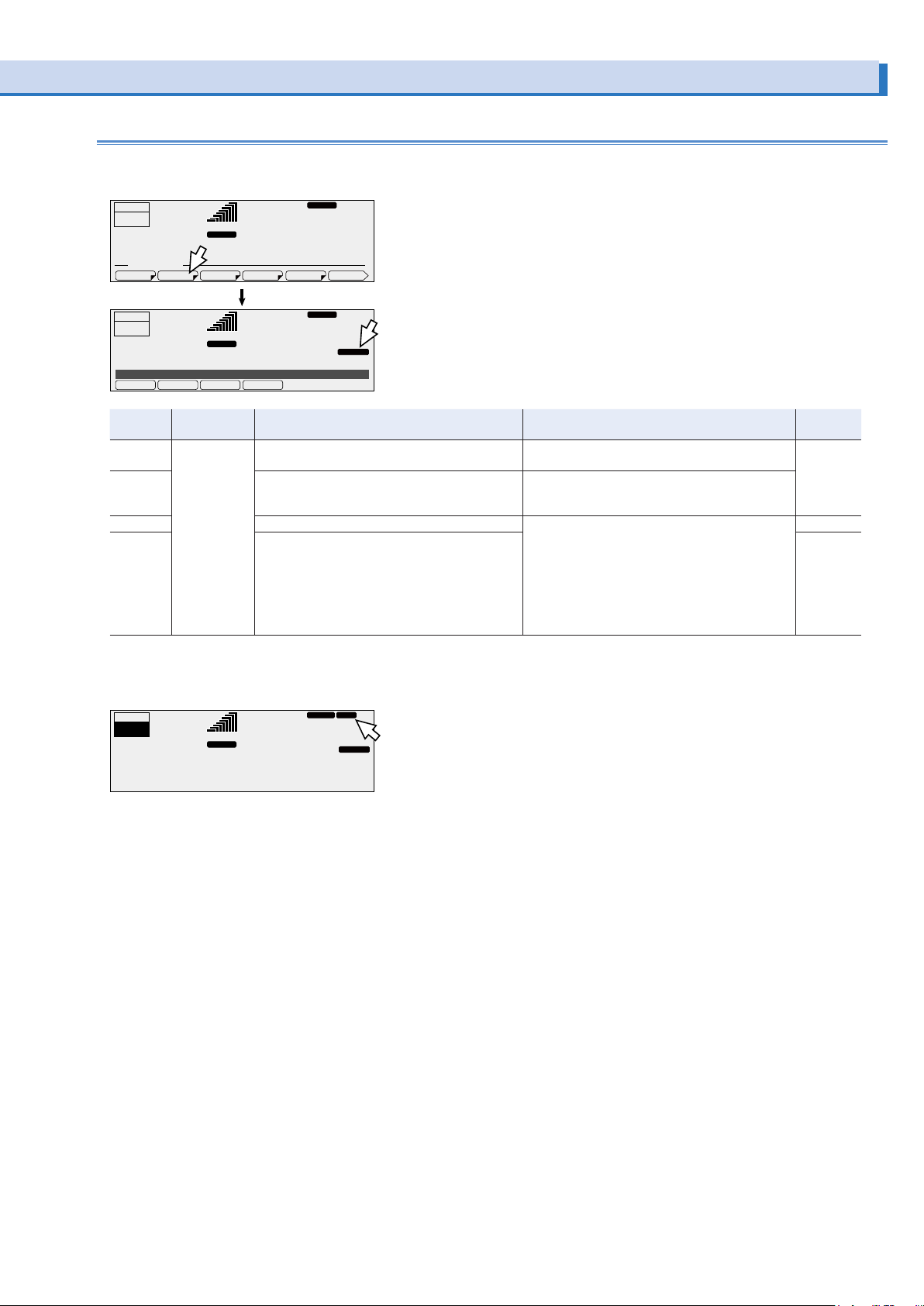
Compensation function setup procedure
ACLOAD
REG ADJSENS.-S
SENS.-HOFF
Press ENT to display this.
ACLOAD
RESP.M
SENS
Set the voltage and the frequency that you want to stabilize at the sensing point. In DC mode, set only the voltage.
Press OTHER (SHIFT+MEMORY), 1/3 (F6), and then COMPEN (F2) to configure the compensation functions.
OUTPUT
OFF
6.87
OTHER. MEMU
COMPEN RESP
OUTPUT
OFF
6.87
Compensation OFF
99.00
RANGE
L
rms rms
A
PON OUTPVCC
50.00
RANGE
L
rms rms
A
RESP.M
Hz
28.1
FILE
RESP.M
AC RESP.MLOAD
Hz
28.1
2/3
V
SENS.-H
V
Item Title Description Conditions in which the function key cannot be
OFF Compensation The compensation (voltage compensation) func-
SENS.-H The hard sensing function is used. Output: on
SENS.-S The soft sensing function is used. Output: on
REG ADJ
*1. Not valid in single-phase three-wire output and three-phase output (optional)
*1
tions are not used.
The regulation adjustment function is used.
Allow a current to flow through the load. Then,
check the voltmeter that is attached across the
load, and use the rotary knob to adjust the PCR-LE
Series voltage to the same value that is displayed.
used
None All
Output impedance: setting
Response: MEDIUM or FAST
Output impedance: setting
Action to perform when the current limit is exceeded: DISABLE
Waveform bank: specified
Soft start: on
Power supply line error simulation: being performed
Sequence: being performed
Valid
modes
AC and DC
AC
If the frequency is less than 40 Hz, soft sensing is disabled. If the output is on and soft sensing is disabled, “SENS” appears on the
screen.
OUTPUT
ON
50.78
Adjusting the regulation adjustment function
A
30.00
RANGE L
pk rms
Hz
102.3
SENS.-S
V
Press OTHER (SHIFT+MEMORY), 1/3 (F6), and then COMPEN (F2) to select REG ADJ (F4). After you have selected the regulation adjustment function, you have to adjust it.
Allow a current to flow through the load. Then, check the voltmeter that is attached across the load, and use the rotary knob to adjust
the PCR-LE Series voltage to the same value that is displayed.
After you have finished adjusting the function, press ESC to return to the home position.
PCR-LE series 49
Page 50

Using the Voltage compensation Function (Cont.)
Checking the sensing functions (excluding
the regulation adjustment function)
When you are using the hard sensing function or soft sensing
function, after you finish wiring the sensing cables, check that
there are no wiring errors. Turn the load’s power switch off before you perform this check.
Turn the POWER switch on.
1
Set the output undervoltage protection (UVP) to 5 V.
2
Set the output overvoltage protection (OVP) to 20 V.
3
Set the output voltage range to the H range.
4
Set the output voltage to 10 V, and then turn the
5
output on.
Check whether a voltage of several tens of volts
6
is being generated.
An output being generated in this situation indicates that
there are connection errors. Check whether the sensing
cables are connected and whether the polarities are correct. If the sensing cables are disconnected or the polarities
are incorrect, a voltage will be applied across the load (at
the sensing point) for approximately one second until the
protection function is activated.
If the sensing cables are not firmly connected, an alarm (ALM07: UVP or ALM-22: SENSING FAILURE) may be generated.
If the polarities of the sensing cables are not correct, an alarm
(ALM-00: OVP) may be generated. Connect the cables correctly.
If you are installing a dedicated terminal block for sensing,
check the sensing function before you connect the load to the
terminal block.
50 PCR-LE series
Page 51

Using Power Line Abnormality Simulations
Voltage increase (pop) Voltage drop (dip)Power outage
V SET
T2=0
T1 T3 T5
In AC mode, you can simulate power supply line errors by
stopping the PCR-LE Series output (to simulate power failures)
and decreasing and increasing the voltage (to simulate voltage
dips and pops).
You can use this to test switching power supplies and other
electronic devices.
A sine wave is generated during the power line abnormality
simulations. Even if you have set a special waveform, a sine
wave will be generated as soon as you execute the power line
abnormality simulation.
You can set these values while output is on or off.
T4=0
V(T3)=0
Parameter Description
T1 This is the voltage regulation start time or the voltage regu-
lation start phase.
This is the time or the phase from the waveform’s positive zero crossing (the point where the signal crosses the
zero axis) to the point where voltage regulations - such as
increases or decreases - start to occur.
T2 This is slope time 1.
For pops, this indicates how much time is required to raise
the voltage to the pop voltage.
For dips, this indicates how much time is required to lower
the voltage to the dip voltage.
T3 This is the voltage regulation time.
For pops, this indicates the length of time that the voltage
will be kept at the voltage that it has been raised to (the
pop voltage).
For dips, this indicates the length of time that the voltage
will be kept at the voltage that it has been lowered to (the
dip voltage).
T4 This is slope time 2.
For pops, this indicates how much time is required to lower
the voltage from the pop voltage to the voltage that is in
use during the period indicated by T5.
For dips, this indicates how much time is required to raise
the voltage from the dip voltage to the voltage that is in use
during the period indicated by T5.
T5 This is the return time or the number of return cycles.
This indicates how long (either as a length of time or as a
number of cycles of the present frequency) the voltage will
be kept at the level that it returns to after a pop or dip is
completed.
T3VOLT This is regulated voltage.
For pops, this is the voltage level that the voltage will be
raised to (the pop voltage).
For dips, this is the voltage level that the voltage will be
lowered to (the dip voltage).
LOOP This is the number of repetitions.
This indicates the number of times that the sequence of
steps defined by T1 to T5 will be repeated.
V SET
V(T3)
T1 T2 T4T3 T5
- Memo -
Voltage regulation start polarity
You can set the zero crossing (the time at which the voltage
becomes zero) that will be the reference for T1 to positive
zero crossing or negative zero crossing by switching the voltage regulation start polarity (POL). You can use this function
to change the phase by 180 °. The PCR-LE Series displays
the output voltage (waveform) of L of the OUTPUT terminal
block, with N as its reference.
Positive zero crossing Negative zero crossing
PCR-LE series 51
Page 52

ACLOAD
ACLOAD
ACLOAD
RESP.M
Using Power Line Abnormality Simulations (Cont.)
Power line abnormality simulation setup procedure
These settings cannot be made if you are using the synchronization function.
Set the steady-state voltage and frequency.
1
Press SIM and then COND (F4) to set the condi-
2
tions. After you have nished conguring the settings, press ESC.
A border is displayed around the item that you are setting.
Press ▲ (to select the upper item) and ▼ (to select the
lower item) to switch between items.
28.1
50.00Hz
28.1
+-
V rms
V rms
RESP.M
OUTPUT
OFF
6.87
POL
A rms
LOAD
6.87
▼
▼
▲
▲
POL:+ T3 VOL: 305.0V LOOP: 9999
T1: 999.9ms T2: 99990ms T3: 999.9ms T4:99990ms T5:1000ms
Simulation STOP
OUTPUT
OFF
SIM.CONDITION
POL : +
T1 TYPE : TIME
T5 TYPE : TIME
T1 TYPE
T5 TYPE
50.00Hz
RANGE
L
LOOP COND EDITRUN
A rms
Press this key to move the border up.
▲
This selects the item above, which can then be set.
▼
Press this key to move the border down.
This selects the item below, which can then be set.
TIME DEG
TIME CYCLE
Item Description Valid
POL - Sets the voltage regulation start
polarity to negative zero crossing
+ Sets the voltage regulation start
polarity to positive zero crossing
T1 TYPE TIME Sets the voltage regulation start
using time
DEG Sets the voltage regulation start
using phase
T5 TYPE TIME Sets the duration that the volt-
age remains at the returned
level using time
CYCLE Sets the duration that the volt-
age remains at the returned
level using cycles
mode
AC
Press EDIT (F5) to set the parameters (T1 to T5
3
and T3 VOLT). After you have nished conguring
the settings, press ESC.
28.1
28.1
RESP.M
V rms
1/2
2/2
V rms
OUTPUT
OFF
6.87
POL:+ T3 VOL: 305.0V LOOP: 9999
T1: 999.9ms T2: 99990ms T3: 999.9ms T4:99990ms T5:1000ms
Simulation STOP
SIM.EDIT 1/2
T1: 999.9ms T2: 99990ms T3: 999.9ms T4:99990ms T5:1000ms
T1 Time 100.0ms
SIM.EDIT 2/2
T3 VOL: 305.0V
V3 Volt 0.0V
A rms
RANGE
LOOP COND EDITRUN
T3 T4T2 T5T1
T3 VOLT
L
50.00Hz
Item Title Description Valid
T1 T1 Time Sets the voltage regulation
start time (0.0 ms to 999.9 ms)
T1 Degree Sets the voltage regulation
start phase (0 deg to 359 deg)
T2 T2 Time Sets slope time 1 (0 ms to 99
990 ms)
T3 T3 Time Sets the voltage regulation
time (0.1 ms to 9 999.0 ms)
T4 T4 Time Sets slope time 2 (0 ms to
99 990 ms)
T5
*1
T5 Time Sets the return time (0 ms to
99 990 ms)
T5 Cycle Sets the number of return
cycles (0 to 999 900)
T3 VOLT T3 Volt Sets the regulated voltage
(L range: 0 V to 152.5 V; H
range: 0 V to 305.0 V)
*1. Depending on how T1 to T4 are set, this may lead or lag by one
cycle.
If you set this to a value that is not an integer multiple of one cycle,
the return time will last longer than the time you have specified
because the PCR-LE Series will wait for a zero crossing during the
T1 execution time.
Select LOOP (F3) to set the number of repetitions.
4
OUTPUT
OFF
6.87
POL:+ T3 VOL: 305.0V LOOP: 9999
T1: 999.9ms T2: 99990ms T3: 999.9ms T4:99990ms T5:1000ms
Simulation STOP
A rms
RANGE
LOOP COND EDITRUN
L
50.00Hz
mode
AC
POL:+ T3 VOL: 305.0V LOOP: 9999
T1: 999.9ms T2: 99990ms T3: 999.9ms T4:99990ms T5:1000ms
Loop 9999
Item Title Description Valid
modes
LOOP Loop Sets the number of repetitions
AC
(1 to 9 999; 9 999 indicates
unlimited repetitions)
52 PCR-LE series
Page 53
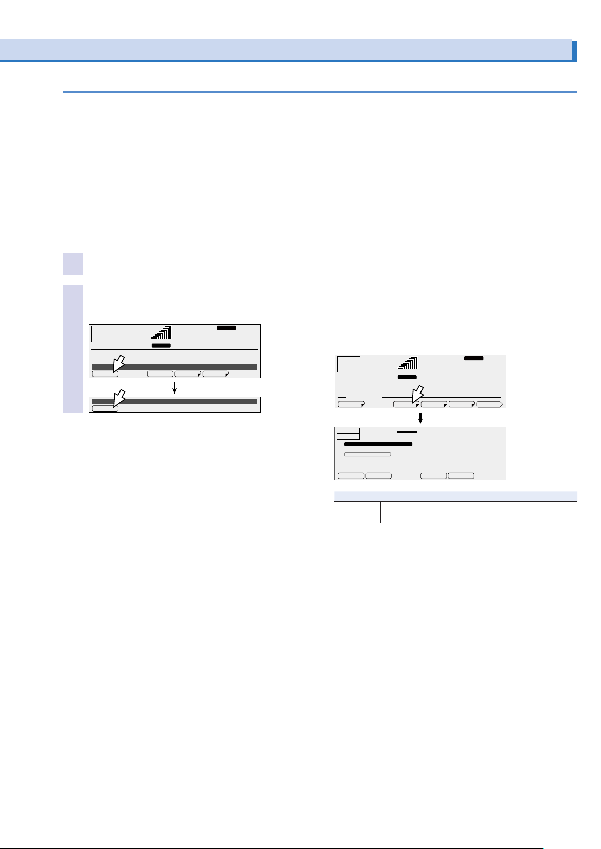
Executing and stopping power line abnormality simulations
ACLOAD
ACLOAD
You cannot execute power line abnormality simulations in the
following situations.
• In DC mode or AC+DC mode.
• When you have configured the PCR-LE Series so that it does
not turn output off when the current limit is exceeded (DISABLE).
• When the regulation adjustment or soft sensing compensation function is in use.
• When the L range is selected and T3 VOLT is set to a value
outside of its range.
• When T3 VOLT is set to a value outside the voltage limits.
Press OUTPUT to turn output on.
1
Press SIM and then RUN (F1) to execute a power
2
line abnormality simulation.
During execution, press STOP (F1) to stop the simulation.
28.1
RESP.M
V rms
OUTPUT
OFF
6.87
POL:+ T3 VOL: 305.0V LOOP: 9999
T1: 999.9ms T2: 99990ms T3: 999.9ms T4:99990ms T5:1000ms
Simulation STOP
実行中
Simulation RUN
STOP
A rms
RANGE
LOOP COND EDITRUN
L
50.00Hz
Status signals
Status signals are only generated during the periods defined
by T2, T3, and T4 (period T3 when T2 and T4 both equal zero).
During single-phase, three-wire output or three-phase output
(optional), status signals are output to the U-phase unit.
Signals are generated from the SEQ STAT OUT terminal (a BNC
connector) on the rear panel of the PCR-LE Series. Use the
configuration settings to set the signal polarity. “H” is approximately 5 V. “L” is approximately 0 V.
The BNC connector is isolated from the PCR-LE Series’ INPUT
and OUTPUT terminal blocks. However, the common line of the
TRIG and STAT signals is shared internally, so it is not isolated
from the BNC connector. Also, the BNC connector is not isolated from the SLOT internal circuits. There is a slight time difference (approximately 100 ms) between the status signal output
and changes to the actual output.
Status signals may be output when you change the settings of
the various parameters.
Press CONFIG (SHIFT+OPR MODE) and then SIG.I/O (F3) to
set the status output polarity. The status signal polarity setting
is shared with the sequence function.
OUTPUT
OFF
CONFIG. MEMU
0.00
50.00
RANGE
L
rms rms
A
RESP.M
Hz
28.1
MODEL IDDISPLAYSIG.I/OCOM-I/F
V
1/2
OUTPUT
OFF
CONFIG. SIGNAL I/O POLARITY
TRIG:IN : POSI
TRIG.OUT : POSI
STAT.OUT : POSI
▲
Item Description
STAT.OUT NEGA Sets the status output to low level
LOAD
0.00
A rms
▼
POSI Sets the status output to high level
NEGA
10.00Hz
0.0
POSI
V rms
PCR-LE series 53
Page 54

When the ramp is on
When the ramp is off
(Increase) (Decrease)
(Increase)
(Decrease)
When the ramp is on
When the ramp is off
Advance the phase over
Delay the phase over
the duration of the step
Using the Sequence Function
Sequence overview
A sequence is a series of settings—values such as the output
voltage, frequency, and time—that are saved in advance and
are then recalled and automatically carried out in order at a
later time.
Sequences are groups of executable units called steps. When
a sequence is executed (run), its steps are executed in order,
starting with the specified starting step. A single execution of a
sequence is completed after the sequence’s specified last step
has been executed.
You can use the jump function to skip steps and repeatedly execute all the steps in the sequence except for those that have
been skipped.
Step 0
Sequence
Step 1
Step 2
…
Step 599
The maximum number
of steps is 600.
Step’s signal change (ramp)
To change the frequency or voltage linearly over the specified
time, select “RAMP ON.” To change the value as a step, select
“RAMP OFF.”
If you specify “RAMP ON” in step 0, the signal will change linearly from the current voltage or frequency.
STEP FREQ AC VOLT
When the ramp is
off
When the ramp is
on
000 50.00Hz 100.0V
001 60.00Hz 132.0V
002 100.0Hz 85.0V
003 200.0Hz 30.0V
Freq 50.00Hz
▼
▲
RAMP ONRAMP OFF
• Signal change of voltage
• Signal change of frequency
First, set the starting step, and then set the sequence conditions.
If the last step of a sequence does not turn the output off, the
output will remain on when the sequence is complete.
• Signal change of phase
During three-phase output (optional), you can set the phase
ramp (leading or lagging). This is effective for varying the line
voltage.
the duration of the step
(LEAD)
U
Signal output and Resuming
(LAG)
VW
U
VW
If the status signal is enabled, a status signal will be output
while a step is being executed.
If the trigger signal output is enabled, a signal is output for several tens of microseconds when a step is executed.
You can apply a trigger signal to resume a paused sequence.
54 PCR-LE series
Page 55
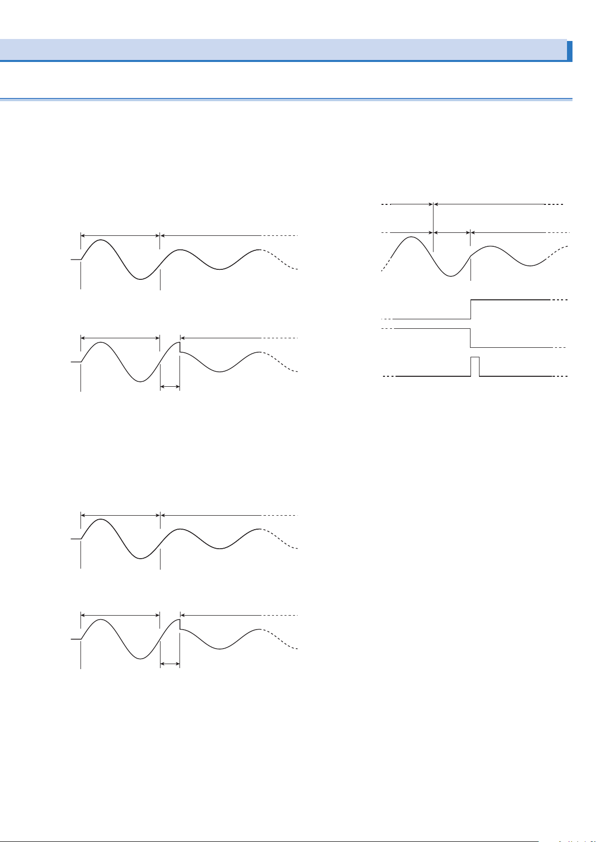
Starting phase angle and the ending phase angle
phase angle is reached before starting the step.
When starting phase angle is not specied (S.PHASE=FREE)
When ending phase angle is not specied (E.PHASE=FREE)
The PCR-LE Series waits until the ending phase angle
is reached and then transitions into the next step.
Step n-1 Step n
Panel display
Elapsed Time
Status signal
Step n: ON
Trigger signal output
Step n: ON
Status signal
Step n-1: ON
Steps are managed in terms of time.
If you set the starting phase angle, steps will start from the
specified phase angle.
Phase wait time is the duration from the point when the step
time of the last step has elapsed to the point where the phase
angle reaches the starting phase angle. The phase wait time is
dependent on frequency.
Display and signal output during the phase wait
time
During the phase wait time, the screen shows the next step
number. The elapsed time remains at zero until the next step
starts.
The status signal is output while the waveform of the step that
is enabled is being output.
Step n-1 Step n
Previous step
The PCR-LE Series transitions into the next step
after the previous step time elapses.
When starting phase angle is 90° (S.PHASE=90 deg)
Step n-1 Step n
Previous step
Phase wait time
The PCR-LE Series waits until the starting
If you set the ending phase angle, the PCR-LE Series will end
the step when the specified phase is reached.
Phase wait time is the duration from the point when the step
time has elapsed to the point where the phase angle reaches
the ending phase angle. The phase wait time is dependent on
frequency.
Step n Step n+1
The PCR-LE Series transitions into the next step
after the previous step time elapses.
When ending phase angle is 90° (E.PHASE=90 deg)
Step n Step n+1
Phase wait time
Next step
Step n-1
Sudden phase change
Phase wait time
Specied phase angle
Step n
If you set both the starting and ending phase angles and specify phase change, the phase will change suddenly.
If you set sudden phase change to ON, you can switch between two steps according to the set phase angles. For example, if you set the step n-1’s ending phase angle to 90°, the
step n’s starting phase angle to 270°, and set sudden phase
change to ON, when the step time of step n-1 elapses and 90°
is reached, a transition is made to step n (270° phase angle).
Jump function
The steps in a sequence are normally executed in order starting with the starting step. However, you can use the jump feature to skip over steps and repeat sets of steps by repeatedly
executing jumps.
Sequence tutorial
Appendix A in the supplied CD-R operation manual contains
sequence tutorials that explain sequence creation basics,
phase angle settings, sudden phase changes, and multi-phase
operation.
PCR-LE series 55
You can output the same waveform regardless of whether you
set the starting phase angle or the ending phase angle.
When a waveform is to be output continuously (the phase does
not change suddenly) and you set both the starting and ending
phase angles, the waveform may be offset by one period. To
avoid confusion, we recommend that you set the starting phase
angle and not the ending phase angle (FREE).
Page 56
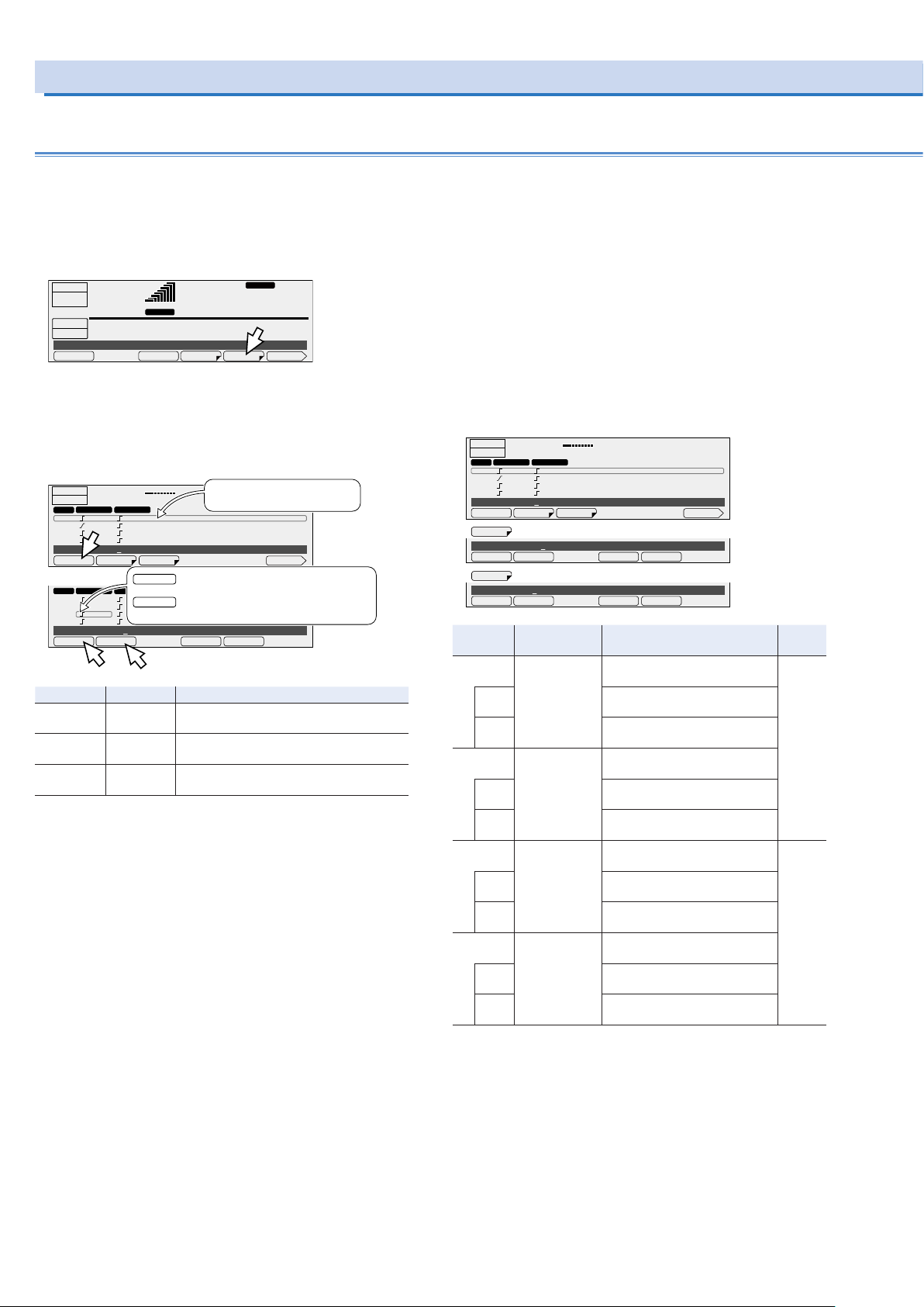
ACLOAD
LOOP COND EDITRUN
1/2
RAMP ONRAMP OFF
▲
▼
Using the Sequence Function (Cont.)
Editing steps
These settings cannot be made if you are using the synchronization function.
There are six types of step editing screens (seven types for single-phase, three-wire output and three-phase output (optional)).
Press SEQ (SHIFT+SIM) and then EDIT (F5) to display the step
editing screen.
OUTPUT
OFF
0.00
SEQUENCE
STOP
Sequence STOP
Items that are common between screens 1/5 to 5/5
A rms
START STEP: 000
END STEP: 000 LOOP: 1
RANGE L
10.00Hz
RESP.M
0.0
V rms
A border is displayed around the step or item that you are setting. First use the rotary knob to specify the step that you want
to configure, and then configure its settings.
OUTPUT
OFF
FREQ ACV
STEP
000 50.00Hz 100.0V
001 60.00Hz 132.0V
002 100.0Hz 85.0V
003 200.0Hz 30.0V
Step 002
STEP FREQ AC VOLT 1/5
STEP FREQ ACV
000 50.00Hz 100.0V
001 60.00Hz 132.0V
002 100.0Hz 85.0V
003 200.0Hz 30.0V
Freq 50.00Hz
▲
LOAD
0.00
A rms
Press this key to move the border up.
▲
This selects step 001, which can then be set.
▼
Press this key to move the border down.
This selects step 003, which can then be set.
▼
Item Title Description
STEP STEP Sets the step (0 to 599) that you want to
▼
▲
-- Sets the next step as the one that you want
-- Sets the previous step as the one that you
Turn the rotary knob, selects
10.00Hz
the step that you want to edit.
0.0
V rms
RAMP ONRAMP OFF
configure
to configure
want to configure
1: Frequency and AC voltage
Use this screen to set the frequency and the AC voltage. The
step signal change can also be set for the frequency and the
AC voltage.
In AC+DC mode, the step’s AC voltage and output voltage can
each be set within their own setting range. If the peak AC+DC
output voltage exceeds the PCR-LE Series’ rated output voltage, the output voltage waveform (the peak section) may be
distorted (clipped).
During single-phase, three wire output and three-phase output
(optional), if you are setting the phases separately, press AC
VOLT (F2) to first set all the phases at the same time, and then
press ACV V (F4) and ACV W (F5) to set the V phase and W
phase, respectively. The AC voltage signal change is shared
between all phases.
OUTPUT
OFF
FREQ ACV
STEP
000 50.00Hz 100.0V
001 60.00Hz 132.0V
002 100.0Hz 85.0V
003 200.0Hz 30.0V
Step 002
STEP FREQ ACV 1/6
FREQ
Freq 50.00Hz
▲
ACV
ACVolt 0.0V
LOAD
0.00
A rms
▼
Item Title Description Valid
FREQ Freq Sets the step’s frequency (1.00
RAMP
OFF
RAMP
ON
*1
ACVOLT
ACVolt
AC PhaseVolt
*1
RAMP
OFF
RAMP
ON
*3
ACV V
ACV W
*1. During single-phase, three-wire output and three-phase output (optional), all
*2. The display during single-phase, three-wire output and three-phase output
*3. Single-phase three-wire output or three-phase output (optional) only
*4. This is shared between all phases. You cannot set it for each phase.
*5. Three-phase output (optional) only
AC V PhaseVolt Sets the step’s AC voltage (0.0 V
RAMP
*4
OFF
RAMP
*4
ON
*5
AC W PhaseVolt Sets the step’s AC voltage (0.0 V
RAMP
*4
OFF
RAMP
*4
ON
phases are set at the same time. Set the voltage using phase voltage.
(optional)
10.00Hz
0.0
V rms
RAMP ONRAMP OFF
Hz to 999.9 Hz)
Disables the ramped frequency
signal change
Enables the ramped frequency
signal change
Sets the step’s AC voltage (0.0 V
to 305.0 V)
Disables the ramped AC voltage
signal change
Enables the ramped AC voltage
signal change
to 305.0 V) (V phase)
Disables the ramped AC voltage
signal change
Enables the ramped AC voltage
signal change
to 305.0 V) (W phase)
Disables the ramped AC voltage
signal change
Enables the ramped AC voltage
signal change
modes
AC and
AC+DC
AC and
AC+DC
56 PCR-LE series
Page 57
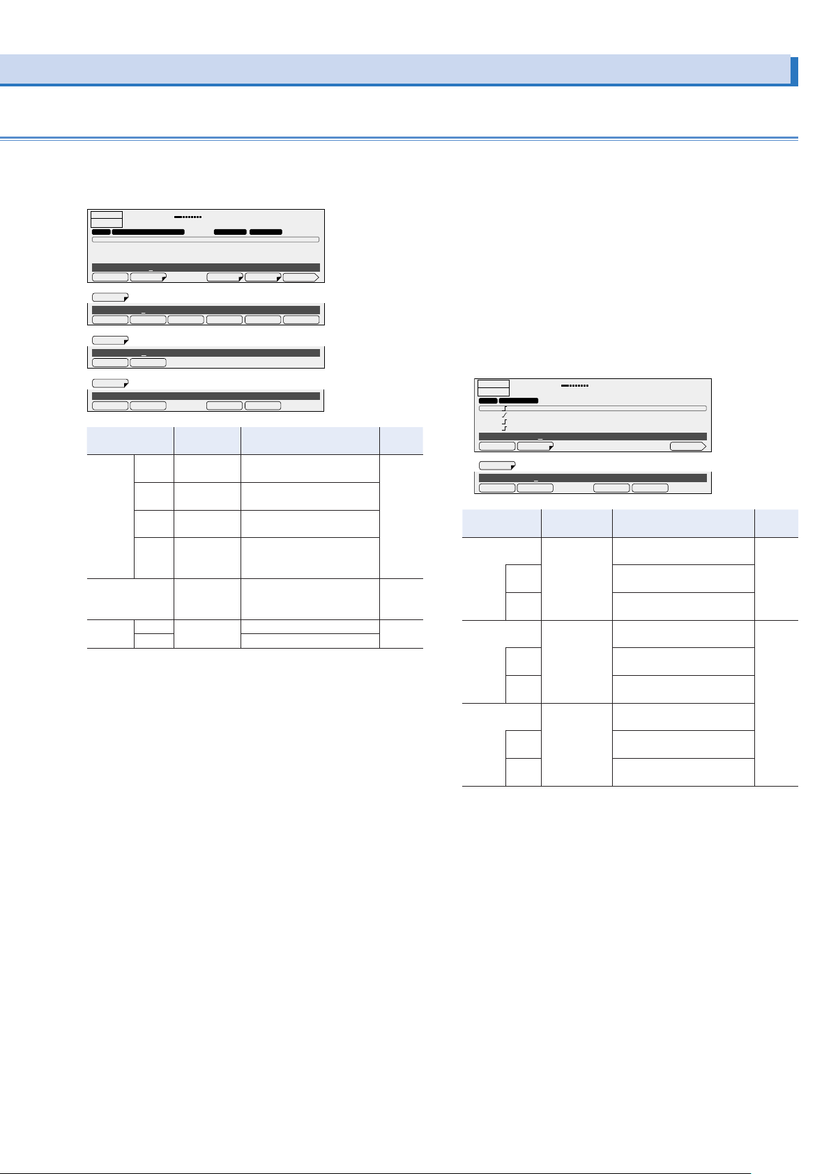
2: Execution time, waveform bank, and output
LOAD
10.00Hz
▲
LOAD
▲
Use this screen to set the step execution time, the waveform
bank, and the output.
OUTPUT
OFF
STEP TIME WB NO. OUTPUT
000 0 : 00 : 03 . 0000 0 ON
001 0 : 00 : 03 . 0000 0 ON
002 0 : 00 : 03 . 0000 0 ON
003 0 : 00 : 03 . 0000 0 ON
Step 002
STEP TIME WB NO OUTPUT 2/6
TIME
Time(SEC) 3
▲
WB NO
WB No.
▲
OUTPUT
Output ON
Item Title Description Valid
TIME HOUR Time(HOUR) Sets the step time’s hours (0
WB NO WB No. Sets the waveform bank
OUTPUT OFF Output Turns the output off All
0.00
A rms
▼
0
▼
▼
0.0
V rms
SEC 100USMINHOUR
ONOFF
hours to 1 000 hours)
MIN Time(MIN) Sets the step time’s minutes
(0 minutes to 59 minutes)
SEC Time(SEC) Sets the step time’s seconds
(0 seconds to 59 seconds)
100US Time(100us) Sets the step time’s micro-
seconds in units of 100 ms (0
ms to 999 900 ms)
number that you want to use
(0 to 63)
ON Turns the output on
modes
All
AC and
AC+DC
3: DC voltage
Use this screen to set the DC voltage. The step signal change
can also be set for the DC voltage.
In AC+DC mode, the step’s AC voltage and output voltage can
each be set within their own setting range. If the peak AC+DC
output voltage exceeds the PCR-LE Series’ rated output voltage, the output voltage waveform (the peak section) may be
distorted (clipped).
If you are setting the voltage of each phase separately for twophase output or three-phase output (optional), press DCV (F2)
to first set all the phases at the same time, and then press
DCV V (F4) and DCV W (F5) to set the V phase and W phase,
respectively. The DC voltage signal change is the same for all
phases.
OUTPUT
OFF
STEP
000 100.0V
001 -100.0V
002 431.0V
003 -431.0V
Step
STEP DCV 3/6
DCV
DCVolt 0.0V
DCV
000
0.00
A rms
▼
Item Title Description Valid
DCV
*1
RAMP
DCVolt
DC Phase-
*2
Volt
OFF
RAMP
ON
DCV V
*3
DC V Phase-
Volt
RAMP
OFF*4
RAMP
ON*4
DCV W
*5
DC W Phase-
Volt
RAMP
OFF*4
RAMP
ON*4
*1. --Single-phase, three-wire output (optional)
For DC mode or single-phase, three-wire output in AC+DC mode (2PMODE
OFF): Set the U phase voltage (the V phase is automatically set to the same
amplitude as the U phase but with opposite polarity).
For two-phase output (2PMODE ON) in AC+DC mode: Set the phase voltage
of all phases at once.
--Three-phase output (optional)
Set the phase voltage of all phases at once.
*2. The display during single-phase, three-wire output and three-phase output
(optional)
*3. Two-phase output and three-phase output only (optional).
*4. This is shared between all phases. You cannot set it for each phase.
*5. Three-phase output only (optional).
10.00Hz
0.0
V rms
RAMP ONRAMP OFF
Sets the step’s DC voltage
(0.0 V to ±431.0 V)
Disables the ramped DC voltage signal change
Enables the ramped DC voltage signal change
Sets the step’s DC voltage
(0.0 V to ±431.0 V) (V phase)
Disables the ramped DC voltage signal change
Enables the ramped DC voltage signal change
Sets the step’s DC voltage
(0.0 V to ±431.0 V) (W phase)
Disables the ramped DC voltage signal change
Enables the ramped DC voltage signal change
modes
DC and
AC+DC
AC+DC
PCR-LE series 57
Page 58
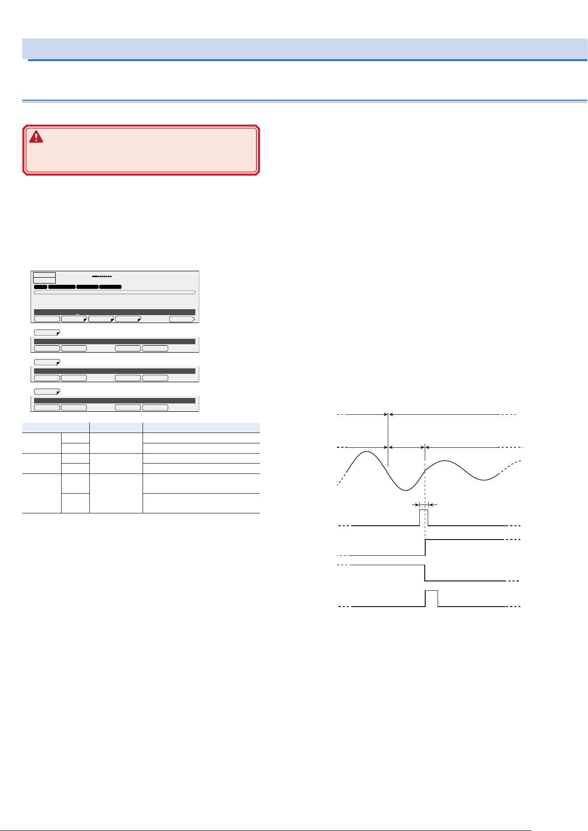
▲
LOAD
Step n-1 Step n
Panel display
Erapsed time
Status signal
Step n: ON
Waiting trigger
Step n: ON
Trigger signal output
Step n: ON
Status signal
Step n-1: ON
Using the Sequence Function (Cont.)
Editing steps (Cont.)
4: Status output, trigger output, and waiting trigger (pause)
WARNING
Risk of electric shock. Use the BNC connector with an
isolation voltage of 63 Vpeak or less.
Use this screen to set the Status output, trigger output, and
waiting trigger.
Use the configuration settings to set the signal polarity. ->
p53
During single-phase, three-wire output or three-phase output
(optional), apply signals to and output signals from the U-phase
unit.
OUTPUT
OFF
STEP
000 OFF OFF OFF
001 OFF OFF OFF
002 OFF OFF OFF
003 OFF OFF OFF
Step
STEP STAT.OUT TRIG.OUT TRIG.IN 4/6
STAT.OUT
Status Out ON
▲
TRIG.OUT
Trig Out OFF
▲
TRIG.IN
Trig In OFF
0.00
STATUS OUT TRIG.OUT TRIG.IN
A rms
000
▼
▼
▼
10.00Hz
0.0
ONOFF
ONOFF
ONOFF
V rms
During single-phase, three-wire output or three-phase output
(optional), apply signals to and output signals from the U-phase
unit.
•
Status signal output (STAT.OUT)
Status signals are only output during the time when the step’s
waveform is being output.
If you set STAT.OUT to “ON,” signals are generated from the
SEQ STAT OUT terminal (a BNC connector) on the rear panel
of the PCR-LE Series.
•
Trigger signal output (TRIG.OUT)
Trigger signals are output during the step’s execution time.
If you set TRIG.OUT to “ON,” signals are generated from the
SEQ TRIG OUT terminal on the rear panel of the PCR-LE Series for several tens of microseconds.
•
Waiting trigger (TRIG.IN)
If set to “ON,” the sequence will be paused after the previous
step is finished, and the PCR-LE Series will wait for a trigger.
If a trigger signal (pulse width of at least 10 μs) is received
through the SEQ TRIG IN terminal, the paused is released,
and the step is executed.
While waiting for the trigger, the screen shows the next step
number. The elapsed time remains at zero until the next step
starts.
Item Title Description
STAT.OUT OFF Status Out Turns status output off
ON Turns status output on
TRIG.OUT OFF Trig Out Turns trigger output off
ON Turns trigger output on
TRIG.IN*1 OFF Trig In Makes the PCR-LE Series not wait
for triggers
ON Makes the PCR-LE Series wait for
triggers (pause)
*1. In the same step, do not turn on both the trigger wait setting and the sud-
den phase change setting (PHAS.CHG). If you do, the sequence cannot be
executed.
The BNC connector is isolated from the PCR-LE Series’ INPUT
and OUTPUT terminal blocks. The common line of the TRIG
and STAT signals is shared internally, so it is not isolated from
the BNC connector.
The remote control function (excluding LAN remote control)
also shares this common line. If you are using a desktop PC to
control the PCR-LE Series remotely, the communication signal
line of the PC is grounded, so the BNC connector will also be
set to ground potential. If the signal line that is connected to the
BNC connector has an electrical potential compared to ground,
the connected device or the PCR-LE Series may be damaged
when a current flows through the signal line.
There is a slight time difference (approximately 100 µs) between the trigger signal output and changes to the actual output.
Trigger signals may also be output when you change the contents of a sequence.
For signal I/O, high level signals are approximately 5 V, and low
level signals are approximately 0 V. For signal input, opening
the terminal is equivalent to applying a high level signal, and
shorting the input is equivalent to applying a low level signal.
Step n-1
Trigger signal input
Sequence paused
until a trigger signal
is received
10 μs or more
Step n
58 PCR-LE series
Page 59

5: Jump function
LOAD
10.00Hz
▲
Step 1 2 3 4 5 6 7 8
The steps are executed in order.
Step 1 2 3 4 5 6 7 8
The step execution order is 1→2→3→6→7→8.
The execution jumps from step 6 to step 3.
The step execution order is
1→2→3→4→5→6→3→4→5→6→3→4→5→6→7→8
Step 1 2 3 4 5 6 7 8
Jump
Jump
Use this screen to set the step type, jump destination step, and
number of times to jump.
OUTPUT
OFF
STEP
000 NORM 0 1
001 NORM 0 1
002 NORM 0 1
003 NORM 0 1
Step 000
STEP TYPE JUMP STEP JUNP CNT 5/6
TYPE
Step Type NORM
▲
JUMP STEP
Jump Step 000
▲
JUMP CNT
Jump Count 1
Item Title Description
TYPE NORM Step Type After this step is completed, the
JUMP STEP Jump Step Sets the jump destination step (0
JUMP CNT Jump Count Sets the number of jump repeti-
0.00
TYPE JUMP STEP JUMP COUNT
A rms
▼
▼
▼
0.0
V rms
JUMPNORM
subsequent step will be executed.
JUMP After this step is completed, the
specified step will be executed.
to 599)
tions (1 to 99 999; 99 999 indicates unlimited repetitions)
Jump function
The steps in a sequence are normally executed in order starting with the starting step. However, you can use the jump feature to skip over steps and repeat sets of steps by repeatedly
executing jumps.
If the step execution time of the jump origin or jump destination
step is less than 500 ms, the peaks of the output voltage waveform of the step that will be executed next may be clipped.
The PCR-LE Series automatically adjusts the power supply voltage (Vcc) of the linear amplifier. If you set the execution time of
the jump origin step to a value less than 500 ms, the PCR-LE
Series cannot perform this automatic adjustment. If the peaks
of the output voltage waveform are clipped, set the execution
time of the previous step to 500 ms or greater, or fix the internal
Vcc.
•
Example of not using the jump function
If you set TYPE to “NORM,” both JUMP and JUMP CNT will
be disabled.
Step TYPE JUMP JUMP CNT
1 to 8 NORM 0 1
•
Example of using the jump function (with no repetitions)
Step TYPE JUMP JUMP CNT
1, 2, and 4 to 8 NORM 0 1
3 JUMP 6 1
Jump origin
Jump destination
The execution jumps over steps 4 and 5.
•
Example of using the jump function (with repetitions)
Step TYPE JUMP JUMP CNT
1 to 5, 7, and 8 NORM 0 1
6 JUMP 3 3
destination
origin
Repeated 3 times
PCR-LE series 59
Page 60

Using the Sequence Function (Cont.)
LOAD
10.00Hz
▲
▼
90 deg
Step n - 1 Step n
270 deg90 deg
Step n - 1 Step n
Step n-1 Step n
the phase suddenly changes to 270 deg
Editing steps (Cont.)
6: Starting phase angle, ending phase angle, sudden phase change, and output impedance
Use this screen to set the starting phase angle, ending phase
angle, sudden phase change, and output impedance.
OUTPUT
OFF
STEP
000 FREE FREE OFF OFF
001 FREE FREE OFF OFF
002 FREE FREE OFF OFF
003 FREE FREE OFF OFF
Step 000
S.PHASE
Start Phase FREE
▲
E.PHASE
End Phase FREE
▲
PHAS. CHG
Phase Change OFF
▲
OUT IMP.
Out Z OFF
Item Title Description
S.PHASE FREE Start Phase Does not set the starting phase
E.PHASE FREE End Phase Does not set the ending phase
PHAS.
CHG*1
OUT IMP. OFF Out Z Does not set the output imped-
*1. In the same step, do not turn on both the trigger wait setting (TRIG.IN) and the
sudden phase change setting. If you do, the sequence cannot be executed.
0.00
START PHASE END PHASE
▼
▼
▼
A rms
PHASE CHANGE OUTPUT IMPEDANCE
0.0
V rms
6/6STEP S.PHASE E.PHASE PHAS. CHG OUT IMP.
FIXEDFREE
FIXEDFREE
ONOFF
ONOFF
angle
FIXED Sets the starting phase angle (0
deg to 359 deg)
angle
FIXED Sets the ending phase angle (0
deg to 359 deg)
OFF Phase Change Does not set the sudden phase
change
ON Sets the sudden phase change
ance
ON Sets the output impedance (out-
put resistance as a percentage:
1 % to 100 %)
- Memo -
Setup example for making sudden phase changes
Appendix A in the supplied CD-R operation manual contains sequence tutorials that explain sequence creation basics, phase
angle settings, sudden phase changes, and multi-phase operation.
First, set the ending phase angle of the step immediately before
the sudden phase change to 90 deg. If the sudden phase change
is set to off, the sequence moves to the next step when the phase
angle reaches 90 deg after the step time of the previous step
elapses, as shown below.
Lastly, set the sudden phase change to on. When the phase angle of the previous step reaches 90 deg, the sequence changes
to the next step. The next step begins at 270 deg.
When step n-1 reaches 90 deg,
of step n.
60 PCR-LE series
Page 61
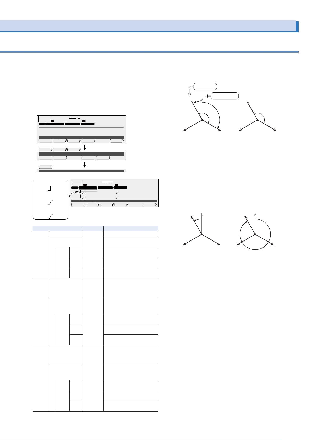
7 Setting the phase difference during single-
LOAD
10.00Hz
W
Actual phase
Advance the phase over
Delay the phase over
W
V
phase, three-wire output and three-phase
output (optional)
Display only when the 2P05-PCR-LE or 3P05-PCR-LE (optional)
is in installed.
Set the phase difference from the U phase that is used when
the PCR-LE Series switches to the next step.
Set this when only one or two phases are to change suddenly
or when performing a phase sweep.
OUTPUT
OFF
STEP
000 OFF OFF OFF
001 OFF OFF OFF
002 OFF OFF OFF
003 OFF OFF OFF
Step 000
U PHA.OFFS
U Phase Offset OFF
▲
ON
When the ramp is off
When the ramp is on
and set to LEAD
LOAD
0.00
U U
UV PHASE UW PHASEU PHASE OFFSET
U PHA.OFFS
UW PHASE
UV PHASE
▼
-
When the ramp is on
and set to LAG
A rms
OUTPUT
OFF
STEP
000 OFF OFF OFF
001 - 0deg OFF + 240deg
002 330deg OFF 270deg
003 + 330deg OFF - 270deg
Step 000
10.00Hz
0.0
V rms
UW PHASEUV PHASE
ONOFF
0.00
U U
U PHA.OFFS
A rms
UV PHASE UW PHASEU PHASE OFFSET
7/7STEP
0.0
V rms
UW PHASEUV PHASE
6/6STEP
+
U phase offset setting.
If you set the U phase offset, the U phase will be offset from
the reference phase. As a result, the U-V/U-W phase difference
settings will be offset from the actual phase difference.
Oset phase
Reference phase
U
U
Phase dierence
setting
Actual
phase
dierence
Setting the phase dierence
V
U
Phase dierence
setting
dierence
USetting the phase dierence
VW
To avoid confusion, we recommend that you turn off the U
phase offset when you use the phase sweep feature. For
details, see “Phase setting for multi-phase output” in the sequence tutorial of the appendix.
Ramp setting
Phase ramp can be set to leading (LEAD) or lagging (LAG).
This is effective for varying the line voltage.
the duration of the step
(LEAD)
330°
0°
U
the duration of the step
(LAG)
330°
0°
U
Item Title Description
U PHA.
OFFS
UV
PHASE
UW
PHASE
*1. Three-phase output (optional) only
OFF U Phase
ON Sets the U phase offset (0 deg
Offset
The U phase offset is not set.
to 359 deg).
RAMP LEAD Sets the U phase change to
leading.
LAG Sets the U phase change to
lagging.
RAMP
OFF
Disables the ramped U phase
change.
OFF UV Phase The phase difference between
U and V is not set.
There is no change from the
previous step.
ON Sets the phase difference
between U and V (0 deg to
359 deg).
RAMP LEAD Sets the V phase change to
leading.
LAG Sets the V phase change to
lagging.
RAMP
OFF
OFF UW Phase The phase difference between
*1
Disables the ramped V phase
change.
U and W is not set.
There is no change from the
previous step.
ON Sets the phase difference
between U and W (0 deg to
359 deg).
RAMP LEAD Sets the W phase change to
leading.
LAG Sets the W phase change to
RAMP
OFF
lagging.
Disables the ramped W phase
change.
V
W
Set an absolute angle for the phase angle.
For details, see “Phase sweep” in the sequence tutorial of the
appendix.
PCR-LE series 61
Page 62
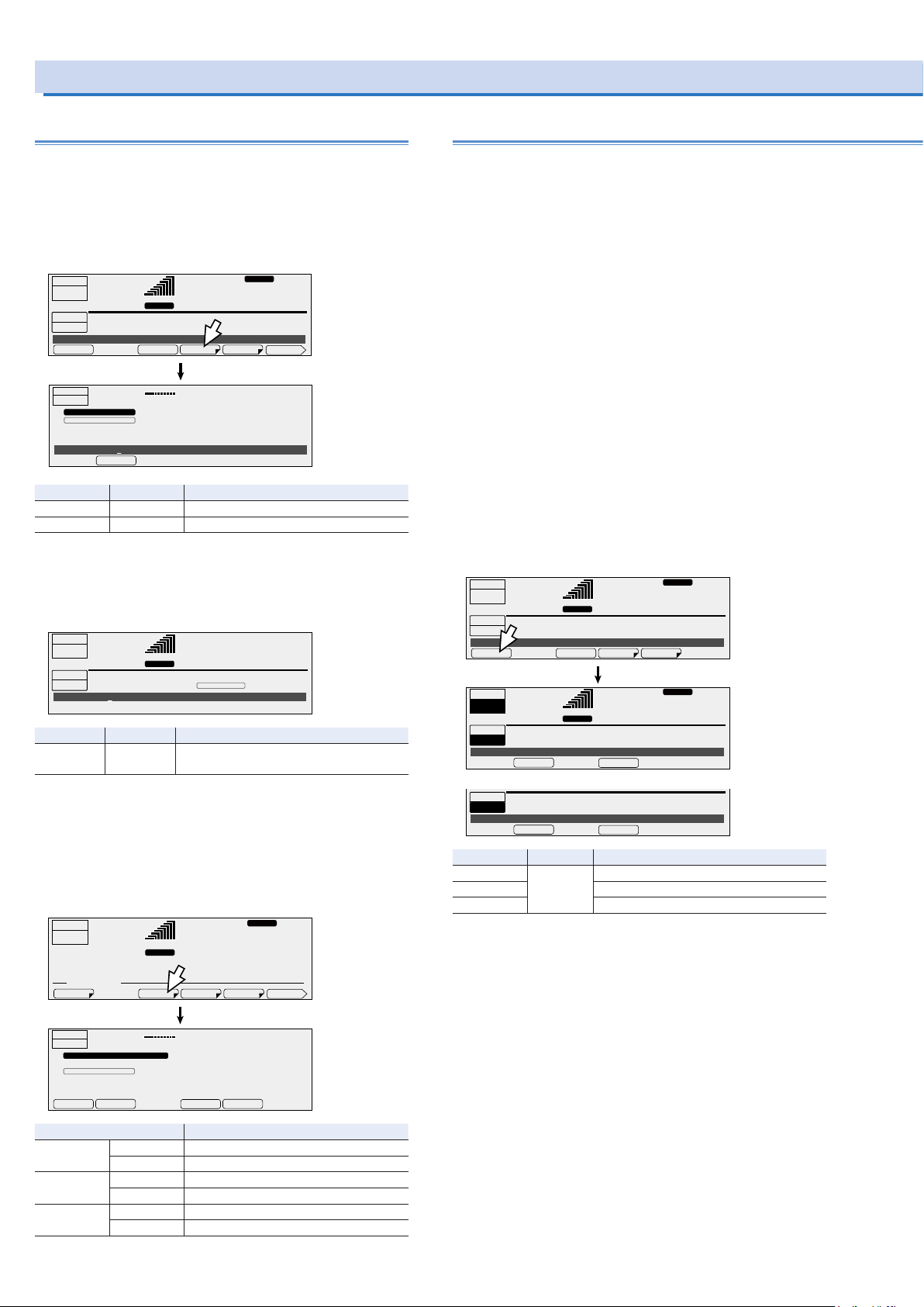
ACLOAD
ACLOAD
AC RESP.MLOAD
NEGA
POSI
Using the Sequence Function (Cont.)
Setting sequence conditions
The items that you set here are shared between all steps.
Setting the starting step number and the ending
step number
On the sequence screen, press COND (F4) to set the starting
step number and the ending step number.
0.0
V rms
10.00Hz
0.0
0.0
V rms
ACLOAD
Hz
28.1
MODEL IDDISPLAYSIG.I/OCOM-I/F
RESP.M
V rms
RESP.M
1/2
V
1/2
OUTPUT
OFF
0.00
SEQUENCE
STOP
Sequence STOP
OUTPUT
OFF
Start Step 000
A rms
START STEP: 000
END STEP: 000 LOOP: 1
LOAD
SEQ. CONDITION
START STEP : 000
END STEP : 008
0.00
▼
RANGE
LOOP COND EDITRUN
A rms
L
10.00Hz
Item Title Description
START STEP Start Step Sets the starting step number (0 to 599)
END STEP End Step Sets the ending step number (0 to 599)
Setting the number of repetitions
On the sequence screen, press LOOP (F3) to set the number of
times that the sequence will be repeated.
OUTPUT
OFF
0.00
SEQUENCE
STOP
Loop 3
A rms
START STEP: 000
END STEP: 000 LOOP: 3
RANGE
L
10.00Hz
Item Title Description
LOOP Loop Sets the number of repetitions (1 to 99 999;
99 999 indicates unlimited repetitions)
Setting the polarity of trigger and status output
Press CONFIG (SHIFT+OPR MODE) and then SIG.I/O (F3) to
set the trigger input polarity, the trigger output polarity, and
the status output polarity. The status signal polarity setting is
shared with that of the power line abnormality simulation function.
OUTPUT
OFF
CONFIG. MEMU
0.00
A
50.00
RANGE
L
rms rms
Executing, pausing, and stopping sequences
After you have finished setting the steps and the sequence
conditions, you can execute the sequence.
On the sequence screen, press “RUN” (F1) to execute the sequence.
You cannot execute the sequence in the following situations.
• When the voltage range is set to the L range and there is a
step whose voltage exceeds the output voltage setting range
(Switch the range to the H range, or set the output voltage so
that it is within the L range).
• When you have configured the PCR-LE Series so that it does
not turn output off when the current limit is exceeded (DISABLE).
• When the regulation adjustment or soft sensing compensation function is in use.
• When the L range is selected and a step’s ACVolt or DCVolt
setting is outside of the L range.
• When the voltage or frequency is set to a value outside the
corresponding limits.
• If there is a step where the trigger wait setting (TRIG.IN) and
the sudden phase change setting (PHAS.CHG) are both
turned on.
OUTPUT
OFF
0.00
SEQUENCE
STOP
Sequence STOP
OUTPUT
ON
SEQUENCE
RUN
Sequence RUN
While a sequence has been paused
SEQUENCE
PAUSE
Sequence PAUSE
A rms
START STEP: 000
END STEP: 000 LOOP: 1
6.87
A rms
001 STEP 0:00:01 LOOP 1/3
STOP
004 STEP 0:00:04 LOOP 1/3
STOP
RANGE
LOOP COND EDITRUN
RANGE
10.00Hz
L
10.00Hz
L
PAUSE
CONTINUE
28.1
Item Title Description
STOP Sequence Stops a sequence that is being executed
PAUSE Pauses a sequence that is being executed
CONTINUE Resumes a sequence that has been paused
You can also resume the execution of a sequence that has
been paused by applying a trigger signal to the SEQ TRIG IN
terminal.
RESP.M
0.0
V rms
RESP.M
ACLOAD
V rms
OUTPUT
OFF
CONFIG. SIGNAL I/O POLARITY
TRIG:IN : POSI
TRIG.OUT : POSI
STAT.OUT : POSI
▲
0.00
▼
LOAD
A rms
10.00Hz
0.0
V rms
Item Description
TRIG.IN NEGA Sets the trigger input to falling edge
POSI Sets the trigger input to rising edge
TRIG.OUT NEGA Sets the trigger output to falling edge
POSI Sets the trigger output to rising edge
STAT.OUT NEGA Sets the status output to low level
POSI Sets the status output to high level
62 PCR-LE series
Page 63

A sequence is complete when all steps are complete. The out-
ACLOAD
OFFS INIT
ACLOAD
1x: 0.00 0.00 0.00 0.00 0.00 0.00 0.00 0.00 0.00 0.00
2x: 0.00 0.00 0.00 0.00 0.00 0.00 0.00 0.00 0.00 0.00
3x: 0.00 0.00 0.00 0.00 0.00 0.00 0.00 0.00 0.00 0.00
put state when the sequence is complete is the state specified
in the last step.
If you want the output to turn off when the sequence is complete, you need to add a last step that turns the output off.
If the U phase is offset in the last step of the sequence (option), the offset (the U PH OFS icon) will remain even when the
sequence is complete. Be sure to press 1/2 and then U PHASE
on the sequence screen to clear the offset. The icon will disappear when you clear the offset.
OUTPUT
OFF
0.00
U
SEQUENCE
STOP
Sequence STOP
U-PHASE
OUTPUT
OFF
U
SEQUENCE
STOP
U Phase Offset Initialize ?
A rms
START STEP: 000
END STEP: 599 LOOP: 1
LOOP COND EDITRUN
SEQ. MEMU
0.00
A rms
START STEP: 000
END STEP: 599 LOOP: 1
RANGE L
RANGE L
U PH
OFS
UNBAL. VOLT
U
U PH
OFS
UNBAL. VOLT
U
RESP.M
10.00Hz
0.0
V rms
Pressing ENT will
clear the icon.
RESP.M
ACLOAD
10.00Hz
0.0
V rms
1/2
2/2
ENT
Using the Harmonic Current Analy-
sis Function
You can perform harmonic analysis of the output current. A
simplified measurement method is used, so this method does
not conform to standards such as IEC. For measurements that
conform to the standards, use the Harmonic/Flicker Analyzer
KHA3000.
If the period is set greater than the aperture time, correct measurements cannot be made.
The harmonic current analysis function is valid in AC mode.
Press OTHERS (SHIFT+MEMORY) and then FFT (F5) to set the
order and the unit.
During single-phase, three-wire output or three-phase output
(optional), press OTHERS (SHIFT + MEMORY), FFT (F5), and
then 1/2 (F6), and then press the key that corresponds to the
phase that you want to set.
Hz
28.1
FFT
99.00Hz
28.1
PCTODD EVEN
RESP.M
V rms
V
1/3
OUTPUT
OFF
6.87
WAVE
A
OUT IMPRISETIM
LOAD
6.87
OTHER. MEMU
OUTPUT
OFF
CURRENT HARMONICS [A] ALL
Order x1 x2 x3 x4 x5 x6 x7 x8 x9 x0
x: 0.00 0.00 0.00 0.00 0.00 0.00 0.00 0.00 0.00 0.00
ALL
99.00
RANGE
L
rms rms
A rms
AMPER
Item Description Valid mode
ALL Selects all the orders AC
ODD Selects all the odd-numbered orders
EVEN Selects all the even-numbered orders
AMPER Sets the unit that is used to display the
harmonic components when the harmonic
component of each order is being displayed
as a current
PCT Sets the unit that is used to display the
harmonic components when the harmonic
current is being displayed as a percentage
with 100 % representing a current that has
*1
U
*1
V
*2
W
*1. Single-phase three-wire output and three-phase output (optional) only
*2. Three-phase output (optional) only
no harmonic current components
Selects the U phase
Selects the V phase
Selects the W phase
PCR-LE series 63
Page 64

Generating Special Waveforms (Waveform bank)
ACLOAD
bank that you want to set, and then
ACLOAD
CANCELAPPLY
You can generate peak-clipped sine waveforms. This is valid in
AC mode and AC+DC mode.
You can use remote control to configure user-defined waveforms. For details, see the Communication Interface Manual on
the included CD-R.
The PCR-LE Series creates reference waveforms for output
voltage by performing D/A conversion on the data that is stored
in its internal memory. One cycle (phase angle of 360°) consists of 10 horizontal bits and 14 vertical bits.
The reference voltage waveform of the PCR-LE Series is a sine
wave. A sine wave whose positive peak is 8191 and negative
peak is -8191 is assigned.
Reference voltage waveform
8191
0
0
-8191
Peak-clipped waveform
•
Waveform bank
512
1023
The stored waveform data in memory that corresponds to
one waveform is referred to as a waveform bank. The PCRLE Series has 64 waveform banks. Each bank is assigned a
number from 0 to 63, which is used to select the waveform.
Waveform bank 0 contains a sine wave that is used as the
PCR-LE Series’ reference voltage waveform. This waveform
bank cannot be overwritten. In the factory default settings, all
waveform banks have the same waveform (sine wave) as the
one that is stored in waveform bank 0.
These settings cannot be made if you are using the synchronization function.
When you turn the power off, the waveform banks from number
24 to number 63 are set to the factory default setting (a sine
wave). Save these waveform banks to a USB memory device
as necessary before you turn the power off.
During single-phase, three-wire output and three-phase output
(optional), the same waveform is assigned to all phases.
Press OTHERS (SHIFT+MEMORY), WAVE (F2), and then EDIT
(F5) to select the waveform (sine wave or peak clipped).
OUTPUT
OFF
6.87
OTHER. MEMU
WB No. 0: SIN
Number of the
waveform bank
that you want to
execute
Edit WB No. 1 : P.C=1.30
WB No.
Number of the
waveform bank
that you want to
set
Item Title Description Valid modes
EDIT WB No. Edit WB No. Specifies the waveform
Edit WB No. 1 : P.C=1.30
SIN Edit WB No. Selects the sine wave
P. C Edit WB No. Sets the crest factor of a
A
WAVE
OUT IMPRISETIM
bank number that you
want to set
peak-clipped waveform
(1.10 to 1.40)
99.00
RANGE
L
rms rms
Select the number of the waveform
select the waveform (sine wave or
peak clipped). For peak-clipped
waveforms, set the crest factor.
P.CSIN
RESP.M
Hz
28.1
FFT
EDITWB No.
CANCELAPPLY
V
1/3
AC and
AC+DC
•
Crest factor
The crest factor is the ratio of the AC waveform’s peak value
to its rms value.
Crest factor = peak value/rms value.
For a sine wave, the crest factor is 1.41. In the voltage wave-
forms of commercial power lines, the peaks are clipped, so
the crest factor is between 1.2 and 1.4.
Generating special waveforms
You can generate special waveforms while output is on or off.
When you have selected the regulation adjustment or soft sens-
ing compensation function, you cannot change the number of
the waveform bank that you want to execute.
Press OTHERS (SHIFT+MEMORY), WAVE (F2), and then WB
No. (F1) to select the number of the waveform bank that you
want to execute.
OUTPUT
OFF
6.87
OTHER. MEMU
WB No. 0: SIN
Edit WB No. 1 : P.C=1.30
Item Title Description Valid modes
WB No. WB No. Specifies the number of the waveform
A
WAVE
OUT IMPRISETIM
bank that you want to execute
99.00
RANGE
L
rms rms
RESP.M
S.WAVE
Hz
28.1
FFT
EDITWB No.
Displayed when you
set WB No. to a value
other than 0
V
1/3
AC and
AC+DC
If the output is on, the selected waveform will be generated. If
the output is off, press OUTPUT to turn the output on and generate the selected waveform.
64 PCR-LE series
Page 65
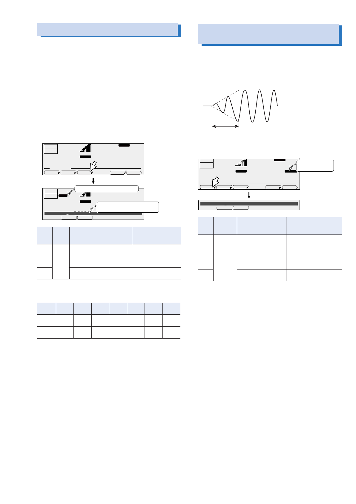
Setting the Output Impedance
ACLOAD
ON OFF
The resistance that corresponds
ACLOAD
ON OFF
The PCR-LE Series’ output impedance (output resistance) is
approximately 0 Ω. Commercial power supplies have an impedance (resistance) of several milliohms to several ohms. You
can set the PCR-LE Series’ output impedance. This enables
you to simulate the same environment as that which is provided
by commercial power supplies.
The impedance that is required for IEC standard tests has
a prescribed inductance component, but the output impedance of the PCR-LE Series consists entirely of resistance. You
can use the PCR-LESeries to perform rough harmonic current
analyses. If you require accurate data, use the Line Impedance
Network (LIN Series).
Setting Soft Starts (The voltage
rise time)
To prevent the output from being turned off (the alarm from being activated) and the voltage from dropping due to the load
device’s inrush current that exceeds the rated capacity of the
PCR-LE Series, you can control the inrush current by having the
output voltage rise gradually when the output is turned on.
Press OTHERS (SHIFT+MEMORY) and then OUT IMP (F3) to
set the output impedance.
OUTPUT
OFF
6.87
OTHER. MEMU
OUTPUT
OUTZ
OFF
6.87
OutZ
Item Title Description Condition in which the
ON OutZ Sets the output impedance as
OFF The output impedance will not
A
WAVE
OUT IMPRISETIM
Displayed when you select “ON”
A
1% 10.00mΩ
a percentage (1 % to 100 %).
The output impedance will be
set.
be set.
99.00
RANGE L
rms rms
99.00
RANGE L
rms rms
to the set percentage
RESP.M
Hz
28.1
FFT
RESP.M
ACLOAD
Hz
28.1
V
1/3
V
function key cannot be
used
Compensation function:
any setting but “OFF”
None
The values in the following table are assigned to the output resistance percentages (1% to 100%).
Rise time
Press OTHERS (SHIFT+MEMORY) and then RISETIM (F1) to
set the soft start.
OUTPUT
OFF
6.87
WAVE
A
OUT IMPRISETIM
0.1s
OTHER. MEMU
Rise Time
Item Title Description Condition in which the
ON Rise Time Sets the rise time (0.1 s
OFF The soft start function
99.00
RANGE
L
rms rms
to 3.0 s).
The soft start function
is turned on.
is turned off.
RESP.M
Hz
28.1
FFT
Displayed when
you select “ON”
RISE TIM
V
1/3
function key cannot be
used
Action to perform when the
current limit is exceeded:
DISABLE
Compensation function:
soft sensing or regulation
adjustment
None
PCR
500LE
L range 0 Ω to
4 Ω
H range 0 Ω to
16 Ω
PCR
1000LE
0 Ω to
2 Ω
0 Ω to
8 Ω
PCR
2000LE
0 Ω to
1 Ω
0 Ω to
4 Ω
PCR
3000LE
0 Ω to
0.667 Ω
0 Ω to
2.667 Ω
PCR
4000LE
0 Ω to
0.5 Ω
0 Ω to
2 Ω
PCR
6000LE
0 Ω to
0.333 Ω
0 Ω to
1.333 Ω
PCR
9000LE
0 Ω to
0.222 Ω
0 Ω to
0.889 Ω
PCR-LE series 65
Page 66
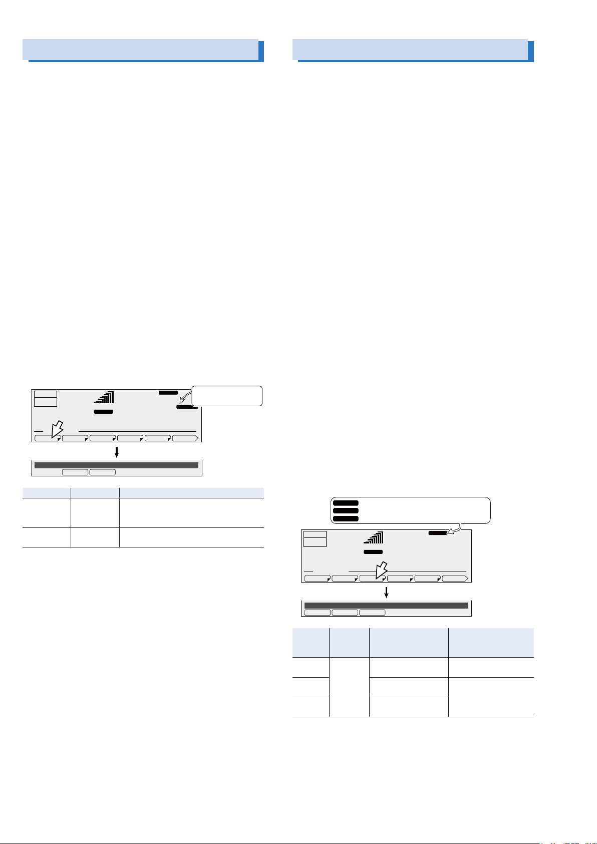
Fixing the Internal Vcc
AUTOFIXED
FASTMEDIUMSLOW
Selecting the Response
To minimize loss in the linear amplifier section, the PCR-LE
Series automatically adjusts the linear amplifier supply voltage
(Vcc) to a level that is suitable for the output voltage. Because
the response speed of the preregulator (DC power supply) that
generates Vcc is slower than that of the linear amplifier, the Vcc
voltage is set internally (only when the output voltage is being
raised) several hundreds of milliseconds before the voltage
output is changed. There will be a time lag before the output
voltage is actually changed even when you frequently change
the output voltage externally.
You can fix the Vcc voltage of the PCR-LE Series. This is useful
when you want to prioritize the output voltage response over
the product’s efficiency.
Fix the PCR-LE Series’ Vcc voltage according to the peak voltage in the output voltage change tests.
When you fix the Vcc, the internal (power) loss increases, so
the protection functions may be activated depending on the
output voltage (the duration that the voltage is generated for),
load conditions, and ambient temperature. Be sure to carry out
tests (simulations) in advance, and check how the PCR-LE Series operates.
If the Vcc is fixed and the maximum used output voltage is set
lower than the peak output voltage, the maximum used output
voltage setting is changed to follow the peak output voltage to
prevent a malfunction.
Press OTHERS (SHIFT+MEMORY), 1/3 (F6), and then VCC (F1)
to set the internal Vcc.
2/3
VCC.FIX
V
Displayed when
you select “FIXED”
RESP.M
OUTPUT
OFF
6.87
OTHER. MEMU
COMPEN RESPVCC
VCCVolt AUTO
Item Title Description
FIXED VCCVolt Sets the maximum output voltage that is
AUTO VCCVolt The Vcc voltage is set automatically (it is
RANGE
rms rms
A
ACLOAD
99.00
L
Hz
28.1
FILE
PON OUTP
used (0 Vpk to 431.0 Vpk).
The Vcc voltage is fixed.
not fixed).
The PCR-LE Series uses a high-speed amplifier. Depending
on the load circuits (especially in the case of capacitive loads)
and the wiring conditions, the output may become unstable
may oscillate.
You can set the response speed of the internal amplifier (to one
of the following three levels) according to the load conditions
and how you will use the PCR-LE Series.
During single-phase, three-wire output, three-phase output,
master-slave parallel control (optional), only soft sensing is
available.
•
High speed response (FAST)
This is only valid on the PCR500LE, PCR1000LE,
PCR2000LE, PCR3000LE, and PCR4000LE.
This is mostly used in research and development, such as in
special tests that require fast rise and fall speeds of power
supplies. Depending on the load conditions, the output may
become unstable (it may oscillate). Check the output voltage
waveform before you actually perform the tests. If the output
is unstable, set the response to MEDIUM or SLOW.
•
Normal speed response (MEDIUM)
This is used in power-supply-environment testing - including
tests such as low-frequency immunity tests - to cover a range
of frequencies from commercial power line frequencies to the
frequencies used by ship and aircraft power supplies.
•
High stable response (SLOW)
This is used to provide stable power to a variety of loads. For
example, this setting would be used on the power supplies
at an EMC test sight. Even if a capacitor that has a large capacity (such as a large noise filter) is connected to the output
of the PCR-LE Series, this setting can be used to provide
stable operations. This setting provides a sufficient response
speed to generate commercial power line frequencies, so it
can also be used in typical evaluation tests.
Press OTHERS (SHIFT+MEMORY), 1/3 (F6), and then RESP (F3)
to set the response.
is displayed when you select “SLOW.”
RESP.S
RESP.M
is displayed when you select “MEDIUM.”
RESP.F
is displayed when you select “FAST.”
RESP.M
99.00
L
PON OUTP
ACLOAD
Hz
28.1
V
2/3FILE
OUTPUT
OFF
OTHER. MEMU
6.87
COMPEN RESPVCC
RANGE
rms rms
A
CV Response MEDIUM
Item Title Description Condition in which the
SLOW CV Re-
MEDIUM Selects the normal
FAST
*1. Invalid in single-phase three-wire output and three-phase output (optional)
sponse
*1
Selects the highly
stable response
speed response
Selects the high speed
response
function key cannot be
used
None
Compensation function:
hard sensing
66 PCR-LE series
Page 67
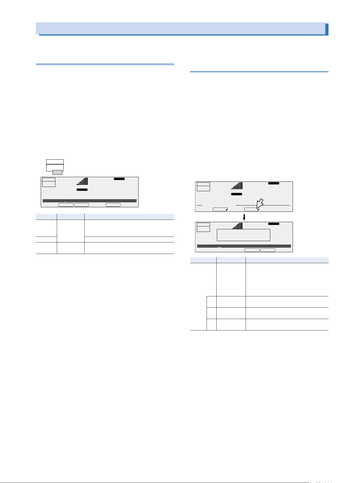
Using the Power Management Functions
Busy status display
ACLOAD
The PCR-LE Series has the following two power management functions: a sleep function and a power-saving function
Sleep function
You can set the PCR-LE Series so that it enters sleep mode
after a certain amount of time passes with its power on but no
output being generated (the output is off).
When sleep mode is enabled and the specified time elapses,
the internal power units turn off, which reduces power consumption.
“zzz...zzz...Please push ESC key” is displayed faintly on the
screen (it scrolls across the screen).
Press ESC to exit sleep mode. You cannot turn the output on for
the few seconds between when sleep mode is exited and the
internal power units turn on (the “Busy” state).
Press SLEEP (SHIFT+1) to set the sleep function.
OUTPUT
OFF
Busy...
RESP.M
99.00
ACLOAD
Hz
28.1
V
OUTPUT
OFF
6.87
Sleep Timer 60min
Item Title Description
ON Sleep Timer The sleep function turns on.
OFF The sleep function turns off.
EXEC -- The PCR-LE Series enters sleep mode in-
RANGE
L
rms rms
A
OFFON EXEC
Sets the time that elapses before the PCR-LE
Series enters sleep mode (1 min to 60 min).
stantly.
Power-saving function (excluding the
PCR500LE and the PCR1000LE)
The PCR-LE Series (excluding the PCR500LE) is made of units.
Each model contains power units that correspond to the rated
output capacity.
If you are using the PCR-LE Series at less than the rated output
capacity, the PCR-LE Series can operate using only the necessary power units. Even if you are not supplying power to a load,
the power units suffer power loss. Operating the PCR-LE Series
with the minimum number of power units reduces power consumption.
This function is invalid on the PCR500LE and PCR1000LE.
Set the maximum power that you will use. If the specified power
capacity is exceeded, the protection functions will be activated.
Master-slave parallel operation (option) is valid only when the
connected PCR-LE Series are of the same model.
Press OPR MODE and the POW SAV (F4).
OUTPUT
OFF
6.87
OPERATION MODE. MEMU
OUTPUT
OFF
6.87
Power Save
Item Title Description
POW SAV Power Save Sets the anticipated maximum power
*2
U
*2
V
*3
W
*1. The setting range during master-slave parallel operation (optional) is “1 kVA ×
the number of parallel units” to “rated output capacity × the number of parallel
units.” The resolution is 1 kVA × the number of parallel units.
*2. Single-phase three-wire output and three-phase output (optional) only
*3. Three-phase output (optional) only
A
Turn the power switch on
to validate the setting value.
A
2kVA
U Power Save Sets the anticipated maximum power of U
V Power Save Sets the anticipated maximum power of V
W Power Save Sets the anticipated maximum power of W
99.00
RANGE
L
rms rms
POW SAVACDC
99.00
RANGE
L
rms rms
kVA to the rated output capacity; resolution: 1 kVA).
Example: If the anticipated maximum
power on a PCR6000LE or PCR9000LE is
4.5 kVA, set this to 5 kVA.
phase
phase
phase
RESP.M
Hz
28.1
RESP.M
ACLOAD
Hz
28.1
CANCELAPPLY
V
V
*1
(1
PCR-LE series 67
Turn the POWER switch off and on to enable the setting.
To clear the power-saving function, set the MAX setting to the
rated output capacity.
Page 68
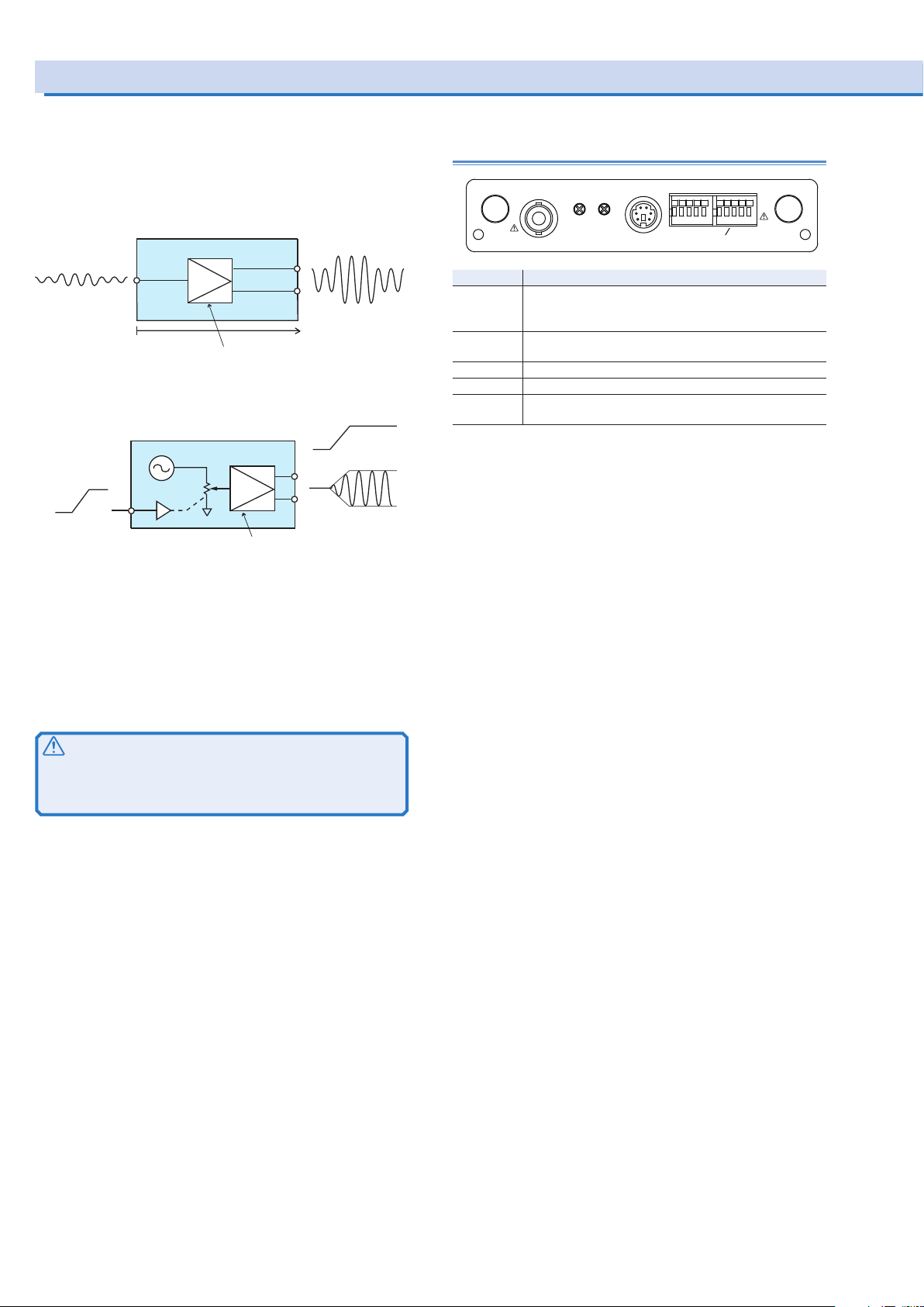
(
r
Controlling the Output Using External Analog Signals
The output can be controlled using external analog signals
by installing the analog signal interface board (EX05-PCR-LE/
EX06-PCR-LE) to the slot3.
For details of installing the board on the PCR-LE, see the setup
guide of EX05-PCR-LE/EX06-PCR-LE.
• Amplifying the input waveform (EX05-PCR-LE only)
Input Output
(Example) 1 VACrms
sine wave
Amplier
100 VACrms
sine wave
GAIN 100x (L range) or 200x (H range)
• Varying the voltage of the output AC waveform using DC signals (EX06-PCR-LE only)
Input
Output
Output AC
voltage
0 V to 150 V o
0 V to 300 V
Example) Input DC
voltage
0 V to 10 V
Sine wave
10 V
Amplier
GAIN 15x (L range) or
30x (H range)
Names and functions of the parts of the analog signal interface board
GAIN
Name Description
INPUT BNC terminal for applying the external signal
Input terminals is electrically isolated from the output
terminals of the PCR-LE.
GAIN Variable resistor for fine adjusting the gain (voltage ampli-
fication ratio)
OFFSET Variable resistor for fine adjusting the offset
AUX This is a connector for options.
SIGNAL I/O Connector for controlling the PCR-LE through external
contacts
AUX
OFFSETINPUT
ANALOG SIGNAL INTERFACE
SIGNAL I O
12345678910
EX0x-PCR-LE
• SIGNAL I/O Connector
• Controlling the PCR-LE through external contacts
You can turn the output on and off, execute and stop se-
quences, clear alarms, and shut down the output.
• Monitoring the operation status
You can monitor the output status, alarm status, busy status,
current peak limit status, and overload status.
CAUTION
You cannot set the voltage limit when the PCR-LE is being
controlled using external analog signals. Accidentally applying an excessive external voltage may damage the load.
68 PCR-LE series
Page 69

Amplifying the input waveform (EX05-PCR-LE only)
ACLOAD
RESP.M
You can use the PCR-LEwith EX05-PCR-LE as a power amplifier that simply amplifies the input waveform or use it to add an
external signal to the PCR-LE Series signal source.
Selecting the signal source
Select which signal source to use to control the PCR-LE Series.
• Internal signal source (INT)
Output the PCR-LE Series signal source. External signal
sources are not used.
• Internal signal source and external signal source (INT+EXT)
Output the sum of the PCR-LE Series signal source and an
external signal source.
If you select INT+EXT, the PCR-LE Series settings will be
changed as follows:
Action to perform when the current limit is exceeded: Turn
the output off
Internal Vcc: FIXED: (previously set value)
Compensation function: OFF (when soft sensing or regula-
tion adjustment is selected)
Displays the phase voltage (Single-phase three-wire output
or three-phase output (optional) only)
• External signal source (EXT)
The EX05-PCR-LE amplifies the external signal (0 Vrms to
1.5 Vrms) 100 times when L range is selected and 200 times
when H range is selected and outputs the resultant voltage.
If you select EXT, the PCR-LE Series settings will be changed
as follows:
Action to perform when the current limit is exceeded: Turn
the output off
Synchronization function: OFF
Output on/off phase control: FREE
Internal Vcc: FIXED: (previously set value)
Compensation function: OFF (when soft sensing or regula-
tion adjustment is selected)
Soft starts: OFF
Displays the phase voltage (Single-phase three-wire output
or three-phase output (optional) only)
Press OTHERS (SHIFT+MEMORY), EXT SIG(F4) and then
SOURCE(F1) to set the signal source.
INT
is displayed when you select “INT”.
EXT+INT
is displayed when you select “INT+EXT”.
is displayed when you select “EXT”.
EXT
OUTPUT
OFF
6.87
OTHER. MEMU
EXT SIGNAL. MENU
Signal Source INT
INT INT+EXT
Item Title Description
INT Signal
EXT Use the external signal.
INT+EXT Use the internal signal
A
WAVE EXT SIG FFTOUT IMPRISETIM 1/3
POLSOURCE MINFREQ
EXT
Use the internal signal. Output on
Source
and external signal.
99.00
RANGE
L
rms rms
ACLOAD
EXT+INT
Hz
28.1
RESP.M
V
Condition in which the function key cannot be used
CAUTION
Risk of malfunction. If you output DC voltage in AC mode, the
protection features will not function properly. If you want to
output DC voltage, use the PCR-LE Series within 70 % of the
rated current, or change the output voltage mode to AC+DC.
Selecting the polarity
Select whether to output a signal whose polarity is the same as
or opposite to that of the input signal.
Press OTHERS (SHIFT+MEMORY), EXT SIG(F4) and then
POL(F2) to set the polarity.
During single-phase, three-wire output and three-phase output
(optional), press OTHERS (SHIFT+MEMORY), EXT SIG(F4),
and then press the key that corresponds to the phase that you
want to set, and then POL(F2) to set the polarity.
OUTPUT
OFF
6.87
OTHER. MEMU
WAVE EXT SIG FFTOUT IMPRISETIM 1/3
RANGE
rms rms
A
L
99.00
EXT+INT
Hz
28.1
V
EXT SIGNAL. MENU
POLSOURCE MINFREQ
Signal Polarity NORM
NORM
INVERT
Item Title Description
NORM Signal Polarity
INVERT Output a signal whose polarity is op-
*1. Single-phase three-wire output and three-phase output (optional) only
*2. Three-phase output (optional) only
U Signal Polarity
V Signal Polarity
W Signal Polarity
Output a signal whose polarity is the
*1
same as the input signal.
*1
*2
posite to that of the input signal.
PCR-LE series 69
Page 70

Controlling the Output Using External Analog Signals (Cont.)
Amplifying the input waveform (EX05-PCR-LE only)
Setting the aperture time (only when using EXT)
To use an external signal source (EXT), set the aperture time.
-> p28
If the aperture time is not set, the voltage and current that are
being output may be different from what are displayed on the
panel.
The aperture time setting was added in firmware version 5.00.
As a result, the function for setting the estimated minimum frequency that was available in firmware version 4.99 and earlier
is no longer available.
Setting the internal Vcc
If you set the signal source to EXT or EXT+INT, the internal Vcc
is changed to a fixed value. Set the Internal Vcc value to the
voltage that you want to output (peak value) + 10 V.-> p66
If the internal Vcc is set to a value greater than the actual output voltage, the protection function may be activated. If the internal Vcc is set to a value less than the actual output voltage,
a few hundred milliseconds of response delay will occur.
Outputting the signal
After you set the signal source, polarity, and the estimated
minimum frequency (EXT only), apply an external signal to the
INPUT terminal.
Check that the POWER switch is turned off.
1
Connect an external signal (generator) to the IN-
2
PUT terminal.
Turn the POWER switch on.
3
Fine adjusting the offset
You can fine adjust the offset by turning the OFFSET variable
resistor using the adjustment screwdriver. Adjust the offset so
that the output voltage is as close to 0 Vdc as possible with the
input terminal shorted.
Fine adjusting the gain
You can fine adjust the gain by turning the GAIN variable resistor using the adjustment screwdriver. Adjust the gain so that the
output voltage is 150 Vac (L range) when 1.5 Vac is applied to
the input terminal.
Functional limitations
If you use an external signal, you will not be able to use the following functions, in addition to the settings that were changed
when you selected the signal source.
• When the internal signal source plus the external signal
source are used
Harmonic current analysis function
• When the external signal source is used
Setting the output voltage, voltage limit
Setting the frequency, frequency limit
Using memory
Special waveforms
Harmonic current analysis function
Power line abnormality simulations
Sequence function
Phase difference (Single-phase three-wire output or three-
phase output (optional) only)
Press the RANGE (SHIFT+8) key to set the voltage
4
range (L/H)
Apply an external signal to the INPUT terminal.
5
Turn the OUTPUT on.
6
70 PCR-LE series
Page 71

Varying the voltage of the output AC waveform using DC signals (EX06-PCR-LE only)
When AC mode or AC+DC mode is selected, the PCR-LE with
EX06-PCR-LE outputs AC voltage ranging from 0 V to 150 V
(when L range is selected) or 0 V to 300 V (when H range is selected) with respect to a DC signal input ranging from 0 V to 10
V.
Selecting the signal source
Select whether to control the output AC voltage using an external signal.
Press OTHERS (SHIFT+MEMORY) and then, VPROG(F4) to set
the signal source.
Displayed when you select “ON”.
RESP.M
L
99.00
ACLOAD
VPROG
Hz
28.1
V
Condition in which the function key cannot be used
OUTPUT on
Soft start: ON
OUTPUT
OFF
6.87
OTHER. MEMU
WAVE VPROG FFTOUT IMPRISETIM 1/3
VProg OFF
ON
Item Title Description
ON VProg Control the AC voltage using
OFF Do not control the AC volt-
RANGE
rms rms
A
OFF
an external signal
age using an external signal
Outputting the signal
After you set the signal source, apply an external signal to the
INPUT terminal.
Check that the POWER switch is turned off.
1
Connect an external signal (generator) to the IN-
2
PUT terminal.
Turn the POWER switch on.
3
Press the OPR MODE > ACDC(F2) to set the out-
4
put mode (AC/ AC+DC).
Press the RANGE (SHIFT+8) key to set the voltage
5
range (L/H).
Press F > FREQ(F1) to set the frequency (1.0 Hz
6
to 999.9 Hz).
Apply an external signal to the INPUT terminal.
7
Turn the OUTPUT on.
8
PCR-LE series 71
Page 72

Controlling the Output Using External Analog Signals (Cont.)
Varying the voltage of the output AC waveform using DC signals (EX06-PCR-LE only)
Fine adjusting the offset and the gain
You can fine adjust the offset by turning the OFFSET variable
resistor using the adjustment screwdriver. You can fine adjust
the gain by turning the GAIN variable resistor using the adjustment screwdriver.
Apply 1 Vdc to the INPUT terminal.
1
Turn the OUTPUT on.
2
Using an adjustment screwdriver, adjust the OFF-
3
SET variable resistor so that the output voltage is
at 15 Vdc (L range).
Apply 10 Vdc to the INPUT terminal.
4
Using an adjustment screwdriver, adjust the GAIN
5
variable resistor so that the output voltage is at
150 Vdc (L range).
Apply 1 Vdc to the INPUT terminal, and check that
6
the output voltage is 15 Vdc (L range). If it is not,
repeat steps 1 to 5 until the output voltage is 15
Vdc (L range).
When you adjust either the offset or the gain, the other value
that you adjusted before may shift. Be sure to double-check
both values.
Functional limitations
If an external signal is used, you will not be able to use the following functions.
Setting the output AC voltage
Soft starts
Power line abnormality simulations
Sequence function
Turn the OUTPUT off.
7
72 PCR-LE series
Page 73
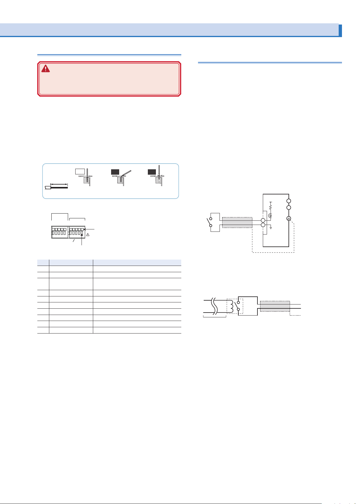
SIGNAL I/O Connector
s
l
PCR-LE
S
connection using an external contact
S
WARNING
Risk of electric shock. Never attempt to connect wires
to the SIGNAL I/O connector while the POWER switch
turned on.
Pin arrangement and connection
To control the PCR-LE Series through external contacts, use
pins 6 to 10 of the SIGNAL I/O connector.
To monitor the operation status of the PCR-LE Series, use pins
1 to 5 of the SIGNAL I/O connector.
Remove the covering from each wire over a distance of 9 mm
to 10 mm (10 mm is recommended).
-
GAUGE
STRIP
AWG 24
10 mm
Pins for control
PCR-LE through
external contacts
Yes
Pins for monitoring
the operation status
12345678910
No No
The wire is directly in
contact with the chassis.
Applicable wires
Single wire: φ0.32 to φ0.64
(AWG28 to AWG22)
Twisted wire: 0.08 mm to 0.3 mm
(AWG28 to AWG22)
Iinsert a 10 mm-strippped wire
The wire scrap is in
contact with the chassis.
Controlling the PCR-LE through external contacts
Wiring
To minimize the influence of noise on the output, use a twocore shielded wire or a twisted-pair wire to connect the control
terminals and the external contact. Make the wires as short as
possible. Susceptibility to the effects of noise increases as the
wires get longer. When wires are long, proper operation may be
hindered even if a cable with anti-noise measures is used.
The release voltage across pins is approx. 12 V maximum, and
the short circuit current is approx. 8.5 mA maximum. (The internal circuit is pulled up to 12 V through 1.3 kΩ.)
Use parts with a contact rating of 12 Vdc and 8.5 mA for the
external contact.
High level input voltage (HIGH): 11 V to 12 V, or open circuit
Low level input voltage (LOW): 0 V to 1 V
When using a shielded cable, connect the shield to the chassis.
Two-core shielded or
twisted-pair wire
SIGNAL I/O
+12 V
1.3 kΩ
6
10
L
terminal
N
Output
Chassi
termina
SIGNAL I O
Insert the wire while holding down this section
with a screwdriver.
Pin Signal Name Description
1 OUTPUT ON STATUS Output on status monitor
2 ALARM STATUS Alarm status monitor
3 OOR STATUS Current peak limit status and Overload
status monitor
4 BUSY STATUS Busy status monitor
5 STATUS COM Output signal common
6 OUTPUT CONTROL Output on/ off control
7 SEQ RUN Sequence execute/ stop
8 ALARM CLR Alarm clear
9 SHUT DOWN Shut down the output
10 COM Input signal common
Example of On/O control
For long-distance wiring
When wiring over a great distance, use a small relay and extend the coil side of the relay.
Two-core shielded or
twisted-pair wire
Extend this
line
Relay
PCR-LE series 73
Page 74
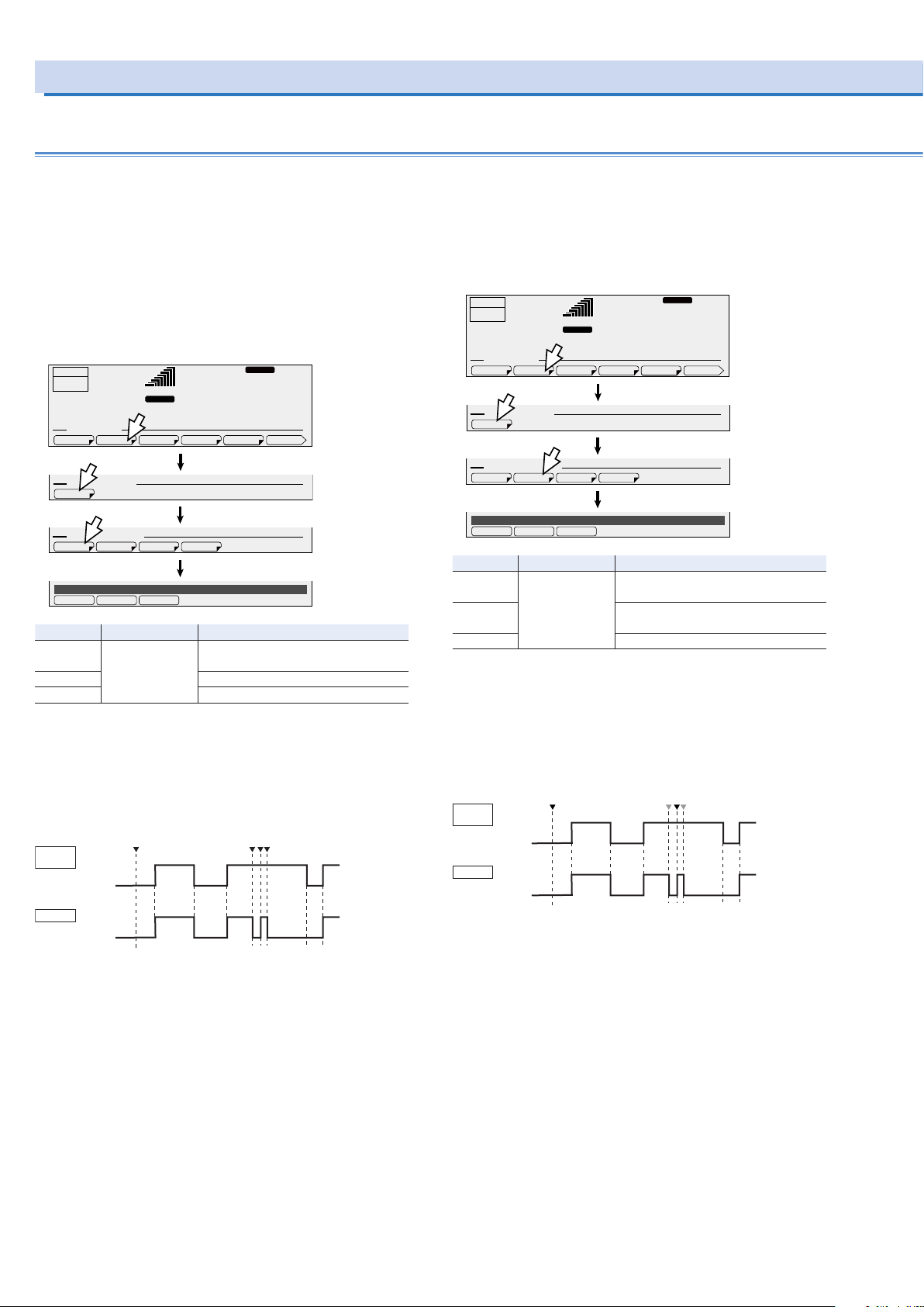
ACLOAD
▼
indicates the point when the OUTPUT key is pressed.
ACLOAD
HIGH
DISABLE LOW
▼
external contacts.
indicates the point when the Run key is pressed.
Controlling the Output Using External Analog Signals (Cont.)
Controlling the PCR-LE through external contacts (Cont.)
Controlling the Output On/ Off
Use pins 6 to 10 of the SIGNAL I/O connector to turn the output
on and off through external contacts.
If multiple units are used under floating conditions and a single
external contact is used to turn on/off the output, isolate the
signal to each unit such as by using a relay on the external
contact signal.
Press CONFIG (SHIFT+OPR MODE), EXT.OPT(F2),
CONTROL(F1) and then, OUTP ON(F1) to set the external control logic of output on/off.
OUTPUT
OFF
6.87
CONFIG. MEMU
EXT OPTION. MENU
CONTROL
EXT CONTROL. MENU
OutputOn Control DISABLE
DISABLE LOW
A
EXT.OPT DISPLAY MODEL IDSIG.I/OCOM-I/F 1/2
SEQ RUNOUTP ON ALMCLR SHUTDOWN
HIGH
99.00
RANGE
L
rms rms
Item Title Description
DISABLE OutputOn Control Do not turn the output on and off
through external contacts.
HIGH Turn the output on with a high signal.
LOW Turn the output on with a low signal.
RESP.M
Hz
28.1
V
If the output is set to off using an external contact, the OUTPUT
key on the front panel is invalid. If you do not want to control the
output through external contacts, set the output control logic to
DISABLE.
The figure below shows an example of output on/off control
when a high level signal turns the output on.
External
contact
H = On
L = O
Output
On
O
The OUTPUT key is
disabled. The output is
not delivered even if
the key is pressed.
The output is on using an
external contact. Thus, the
OUTPUT key is enabled.
To output again using
an external contact,
turn it o once.
Controlling the Sequence Execute/Stop
Use pins 7 to 10 of the SIGNAL I/O connector to turn the sequence execute and stop through external contacts.
Press CONFIG (SHIFT+OPR MODE), EXT.OPT(F2),
CONTROL(F1) and then, SEQ RUN(F2) to set the external control logic of sequence run/stop.
OUTPUT
OFF
6.87
CONFIG. MEMU
EXT OPTION. MENU
CONTROL
EXT CONTROL. MENU
SeqRun Control DISABLE
A
EXT.OPT DISPLAY MODEL IDSIG.I/OCOM-I/F 1/2
SEQ RUNOUTP ON ALMCLR SHUTDOWN
99.00
RANGE
L
rms rms
Item Title Description
DISABLE SeqRun Control Do not execute/stop the sequence
through external contacts.
HIGH Execute the sequence with a high
signal.
LOW Run the sequence with a low signal.
RESP.M
Hz
28.1
V
When a sequence is stopped through external contacts, RUN
(F1) on the front panel is invalid. If you do not want to control
the sequence through external contacts, set the output control
logic to DISABLE.
The figure below shows an example of sequence execute/stop
control when a high level signal execute the sequence.
▼
indicates the point when the Stop key is pressed.
External
contact
H = On
L = O
Sequence
Run
Stop
RUN (F1) is invalid.
Sequence will not
run even if pressed.
RUN (F1) and STOP (F2)
are valid because the
sequence is running
through the use of
To control the sequence
through external contacts
again, rst stop the
sequence.
When a sequence is running, the output on/off control through
external contacts is invalid.
74 PCR-LE series
Page 75
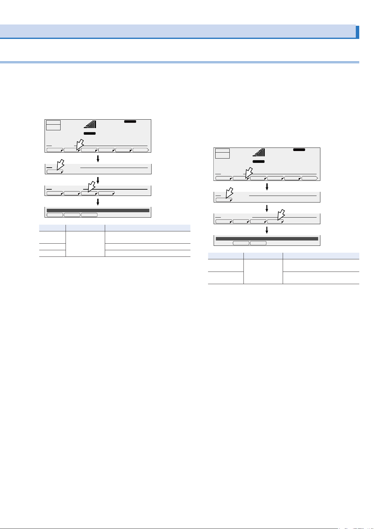
Clear alarms
ACLOAD
ACLOAD
Use pins 8 and 10 of the SIGNAL I/O connector to clear alarms
through external contacts.
Press CONFIG (SHIFT+OPR MODE), EXT.OPT(F2),
CONTROL(F1) and then, ALMCLR(F3) to set the external control logic of alarm clear.
OUTPUT
OFF
6.87
CONFIG. MEMU
EXT OPTION. MENU
CONTROL
EXT CONTROL. MENU
AlarmClr Control DISABLE
DISABLE LOW
Item Title Description
DISABLE AlarmClr Control Do not clear alarms through external
HIGH Alarm clear with a high signal.
LOW Alarm clear with a low signal.
A
EXT.OPT DISPLAY MODEL IDSIG.I/OCOM-I/F 1/2
SEQ RUNOUTP ON ALMCLR SHUTDOWN
HIGH
99.00
RANGE
L
rms rms
contacts
RESP.M
Hz
28.1
V
Shut down the output
Use pins 9 and 10 of the SIGNAL I/O connector to shut down
the output through external contacts. This takes precedence
over the feature that turns the output on and off through external contacts.
When the output is shut down, “TRBL-19 EXT.SHUTDOWN” appears on the panel.
Press CONFIG (SHIFT+OPR MODE), EXT.OPT(F2),
CONTROL(F1) and then, SHUTDOWN(F4) to set the external
control logic of shutdown.
OUTPUT
OFF
6.87
CONFIG. MEMU
EXT OPTION. MENU
CONTROL
EXT CONTROL. MENU
Shutdown Control OPEN
Item Title Description
OPEN Shutdown Control Turn output off with open circuit
SHORT Turn output off with short circuit
A
EXT.OPT DISPLAY MODEL IDSIG.I/OCOM-I/F 1/2
SEQ RUNOUTP ON ALMCLR SHUTDOWN
OPEN
SHORT
99.00
RANGE
L
rms rms
RESP.M
Hz
28.1
V
(input voltage: 11 V to 12V).
(input voltage: 0 V to 1 V).
Recovery
Turn the POWER switch off.
If the external control logic is OPEN, short pins 9 and 10, and
turn the POWER switch on.
If the external control logic is SHORT, open pins 9 and 10, and
turn the POWER switch on.
PCR-LE series 75
Page 76
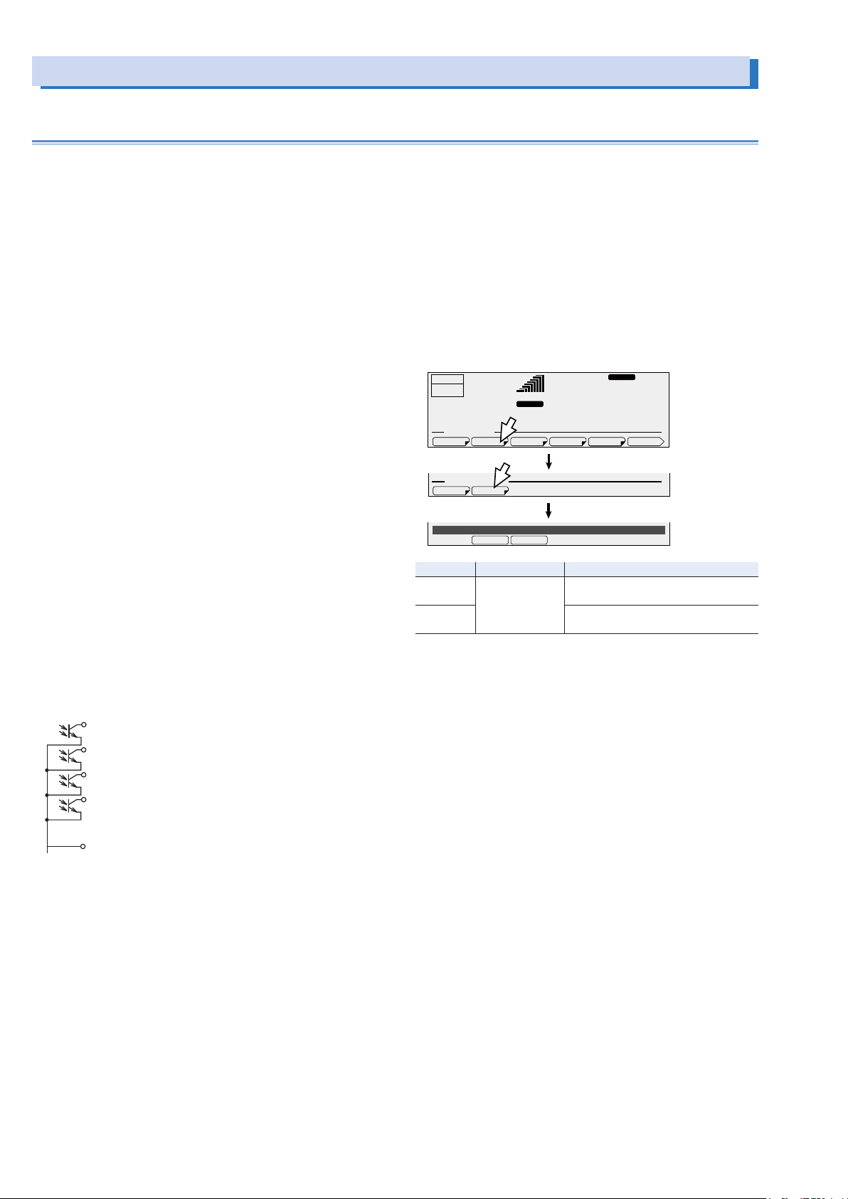
Controlling the Output Using External Analog Signals (Cont.)
1 OUTPUT ON STATUS
ACLOAD
TOTAL
EACH
Monitoring the operation status
You can externally monitor the following operation status of the
PCR-LE.
• Output (OUTPUT ON STATUS)
Use pins 1 and 5 of the SIGNAL I/O connector.
The signal turns on when the output is on.
• Alarm occurrence (ALARM STATUS)
Use pins 2 and 5 of the SIGNAL I/O connector.
The signal turns on when an alarm or trouble occurs.
• Current peak limit and overload (OOR STATUS)
Use pins 3 and 5 of the SIGNAL I/O connector.
The signal turns on when the current limit is exceeded
(OVERLOAD indication) and when current peak is being limited (IPKLIM indication).
• Busy (BUSY STATUS)
Use pins 4 and 5 of the SIGNAL I/O connector.
The signal turns on when the output cannot be turned on
(busy status).
For a few seconds when the sleep function is disabled
For approx. 0.6 seconds when the output voltage range is
switched
For approx. 120 seconds when the current limit is exceed-
ed
For approx. 120 seconds when the internal semiconductor
protection is activated
For a few seconds when the output phase is switched
For a few seconds when the output method for single-
phase three-wire output is switched
The output signals are open collector outputs of photocouplers
(30 Vdc, 8 mA); they are insulated from the internal circuits of
the PCR-LE.
Maximum voltage: 30 V
Maximum current (Sink): 8 mA
Selecting the phase to monitor (single-phase,
three-wire output and three-phase output option)
If you want apply current peak limit and overload monitoring
(OOR STATUS) during single-phase three-wire output or threephase output, you can select whether to monitor the entire system or each phase. To monitor each phase, an analog signal
interface board must be installed for the phase that you want to
monitor.
Press CONFIG (SHIFT+OPR MODE), EXT.OPT (F2), STAT.OUT
(F2) and then, LMT STAT (F1) to select the phase that you want
to monitor.
OUTPUT
OFF
6.87
CONFIG. MEMU
EXT OPTION. MENU
OOR Status Out SYSTEM
Item Title Description
TOTAL OOR Status Out Monitor the entire system and output
EACH Monitor the phase for which the board
A
EXT.OPT DISPLAY MODEL IDSIG.I/OCOM-I/F 1/2
STAT.OUTCONTROL
99.00
RANGE
L
rms rms
the status.
is installed and output the status.
RESP.M
Hz
28.1
V
2 ALARM STATUS
3 OOR STATUS
4 BUSY STATUS
5 STATUS COM
76 PCR-LE series
Page 77
- Specications -
Main Unit Specications
Unless specified otherwise, the specifications are for the following settings and conditions.
The warm-up time is 30 minutes (with current flowing).
TYP: These are typical values that are representative of situations where the PCR-LE Series operates in an environment with an ambient temperature of 23 °C (73.4 °F). These values do not guarantee the performance of the PCR-LE Series.
set: Indicates a setting.
reading: Indicates the readout value.
Input (AC rms)
Nominal
input
voltage
Input
voltage
range
Nominal input Frequency 50 Hz to 60 Hz
Input frequency range 47 Hz to 63 Hz
Apparent power Approx.
Power factor 0.97 (TYP)
Max.
current
*1. 100 V input type or 200 V input type
*2. When the input voltage is 100 V or 200 V, the output voltage is 100 V or 200 V, the output current is the rated value, the load power factor is 1, and the output frequency is
*3. When the input voltage is 200 V, the output voltage is 100 V or 200 V, the output current is the rated value, the load power factor is 1, and the output frequency is between
*4. When the input voltage is 85 V (Single phase two-wire input 100 V input type), 170 V (Single phase two-wire input 200 V input type and Three-phase-three-wire input),
Single-phase
two-wire input
Three-phase
three-wire input
Three-phase
four-wire input
Single-phase
two-wire input
Three-phase
three-wire input
Three-phase
four-wire input
Single-phase
*4
two-wire input
Three-phase
three-wire input
Three-phase
four-wire input
between 40 Hz and 999.9 Hz.
40 Hz and 999.9 Hz.
187 V (Three-phase Four-wire input).
PCR500LE PCR1000LE PCR2000LE PCR3000LE PCR4000LE PCR6000LE PCR9000LE
100 Vac to 120 Vac, 200 Vac to 240 Vac
---
---
85 Vac to 132 Vac, 170 Vac to 250 Vac
---
---
*2
0.93 kVA
11.3 A, 5.5 A*122.0 A, 10.8 A*144.0 A, 21.5 A*166.0 A, 32.0 A*188.0 A, 43.0 A*164.0 A ---
--- 38 A 55.0 A
--- 21 A 30 A
Approx.
*2
1.8 kVA
*2
*1
*1
Approx.
3.6 kVA
200 Vac to 240
Vac
200 Vac to 240 Vac
220 Vac to 240 Vac (phase voltage)
170 Vac to 250
Vac
170 Vac to 250 Vac
187 Vac to 254 Vac (phase voltage)
*2
Approx.
5.5 kVA
*2
Approx.
7.3 kVA
*2
Approx.
10.6 kVA
0.97 (TYP)
*3
---
---
Approx.
*3
15.7 kVA
*3
PCR-LE series 77
Page 78

Main Unit Specications (Cont.)
AC mode output (AC rms)
Voltage (output
L range, output
H range)
Max. current (output L range,
output H range)
Rating 1 V to 150 V, 2 V to 300 V
Setting range 0 V to 152.5 V, 0 V to 305.0 V
Resolution 0.1 V
Accuracy
*2
*1
±(0.3 % of set + 0.6 V)
5 A, 2.5 A 10 A, 5 A 20 A, 10 A 30 A, 15 A 40 A, 20 A 60 A, 30 A 90 A, 45 A
Phase Single-Phase
PCR500LE PCR1000LE PCR2000LE PCR3000LE PCR4000LE PCR6000LE PCR9000LE
Power capacity 500 VA 1 kVA 2 kVA 3 kVA 4 kVA 6 kVA 9 kVA
Maximum peak current Maximum current (rms) x 4 (TYP)
Maximum reverse current
Load power factor 0 to 1 (leading or lagging)
Frequency
*1. When the output frequency is between 45 Hz and 65 Hz, with no load, and at 23°C±5°C.
*2. When the maximum voltage is between 1 V and 100 V (L range) or 2 V and 200 V (H range) and the load power factor is between 0.8 and 1.
*3. For capacitor-input rectifier loads, (at near the peak of the voltage waveform, excluding three-phase three-wire output).
*4. When the output voltage is 100 V or 200 V and the output frequency is between 40 Hz and 999.9 Hz (current is -90 deg to -180 deg/ 90 deg to 180 deg out of phase with
*5. The frequency is limited to the range from 1 Hz to 500.0 Hz when the 3P05-PCR-LE(500HZ LMT) is installed in the PCR-LE series.
*2
When the output voltage is between 100 V and 150 V (L range) or 200 V and 300 V (H range), the output current is reduced by the output voltage.
When the load power factor is between 0 and 0.8, the output current is reduced by the load power factor.
When the output frequency is between 1 Hz and 40 Hz, the output current is reduced by the output frequency.
The peak current that can be output decreases in accordance with the reduction in the absolute value of the instantaneous output voltage.
“Instantaneous output voltage versus instantaneous peak current ratio” (figs 5 and 6) for the representative voltage settings of each range is indicated in “Rated output
current characteristics (Derating)”(-> p83).
the output voltage).
*4
30 % of the maximum current (rms)
Setting range 1 Hz to 999.9 Hz
Resolution 0.01 Hz (1.00 Hz to 100.0 Hz), 0.1 Hz (100.0 Hz to 999.9 Hz)
Accuracy ±1 × 10
*5
-4
*3
*2
DC mode output
Voltage (output L
range, output H
range)
Maximum current
Maximum instantaneous current
Rating -1.4 V to -212 V and +1.4 V to +212 V, -2.8 V to -424 V and -2.8 V to -424 V
Setting range -215.5 V to +215.5 V, -431.0 V to +431.0 V
Resolution 0.1 V
accuracy
*2
*1
±(0.05 % of set + 0.05 V, 0.1 V)
3.5 A, 1.75 A 7 A, 3.5 A 14 A, 7 A 21 A, 10.5 A 28 A, 14 A 42 A, 21 A 63 A, 31.5 A
*3
Maximum current (rms) × 3.6
Power capacity 350 W 700 W 1.4 kW 2.1 kW 2.8 kW 4.2 kW 6.3 kW
PCR500LE PCR1000LE PCR2000LE PCR3000LE PCR4000LE PCR6000LE PCR9000LE
*1. With no load at 23°C±5°C.
*2. When the output voltage is between 100 V and 212 V (L range), 200 V and 424 V (H range), the output current is reduced by the output voltage.
*3. Limited by the rated output current's rms value.
AC + DC mode output
Voltage setting The AC voltage setting range is the same as the range in AC mode.
Maximum current The same as the setting in DC mode
Maximum instantaneous current
Power capacity The same as the setting in DC mode
Frequency The same as the setting in AC mode
Setting range Resolution Setting accuracy
AC voltage setting + DC volt-
The DC voltage setting range is the same as the range in DC mode.
age setting
However, the peak AC+DC voltage must be within the DC voltage setting range.
78 PCR-LE series
Page 79
Output voltage stability
Line regulation
Load regulation (output L range,
output H range)
Output frequency
variation
*1
*2
*3
Response: FAST Within ±0.2 % ---
Response: MEDIUM Within ±0.3 %
Ripple noise in DC mode (5 Hz to 1
MHz components)
Ambient temperature variation
*1. With respect to changes in the rated range of input voltage.
*2. With respect to 0 % to 100 % changes in the ratingof output current.
When the output voltage is between 80 V and 150 V (L range) or 160 V and 300 V (H range) and the load power factor is 1. At the output terminal block. When the response mode is set to FAST or MEDIUM.
*3. Between 40 Hz and 999.9 Hz.
When the output voltage is between 80 V and 150 V (L range) or 160 V and 300 V (H range) and the load power factor is 1. This is the output line regulation with 200 Hz as
the reference.
*4. With respect to changes in the operating temperature range.
When the output voltage range is 100 V or 200 V and the output current is 0 A.
*4
PCR500LE PCR1000LE PCR2000LE PCR3000LE PCR4000LE PCR6000LE PCR9000LE
Within ±0.1 %
Within ±0.1 V, within ±0.2 V
0.15 Vrms or less 0.2 Vrms or less 0.25 Vrms or less
±100 ppm/°C(TYP)
Output frequency stability, output voltage waveform distortion ratio, output voltage response
speed, efciency
Output frequency stability
Output voltage
waveform distortion
*1
Response: FAST 0.2 % or less ---
Response: MEDIUM 0.3 % or less
ratio*2
Output voltage
response speed
Response: FAST 20 µs(TYP) ---
*3
Response: MEDIUM 30 µs(TYP)
Efficiency 54 % or more,
*1. For changes within the rated ranges of all specifications
*2. When the output voltage is between 80 V and 150 V (L range) or 160 V and 300 V (H range) and the load power factor is 1.
*3. When the output voltage is 100 V or 200 V, the load power factor is 1, and the output current changes from 0 A to the rated value and from the rated value to 0 A.
*4. When the input voltage is 100 V or 200 V, the output voltage is 100 V or 200 V, the output current is the rated value, the load power factor is 1, and the output frequency is
between 40 Hz and 999.9 Hz.
*5. When the input voltage is 200 V, the output voltage is 100 V or 200 V, the output current is the rated value, the load power factor is 1, and the output frequency is between
40 Hz and 999.9 Hz.
PCR500LE PCR1000LE PCR2000LE PCR3000LE PCR4000LE PCR6000LE PCR9000LE
Within ±5×10
56 % or more
-5
55 % or more, 57 % or more
*4
*4
58 % or more
*5
Meters (uorescent display)
Voltmeter
Ammeter
Wattmeter
*1
*1
*4
Frequencymeter
*1. With the true rms display, a waveform with a crest factor of 3 or less, DC, output frequency between 40 Hz and 999.9 Hz, RMS, and AVE.
*2. 10 V to 424 V and at 23°C±5°C.
*3. 5 % of the max. rated current to max. rated current and at 23°C±5°C.
*4. When the output frequency is between 45 Hz and 65 Hz.
*5. 10 % to 100 % of the rated output capacity, when the load power factor is 1, and at room temperature.
*6. Displays the output frequency setting (frequency of the internal reference voltage).
Resolution 0.1 V
Accuracy
Resolution 0.01 A 0.1 A
Accuracy
Resolution 0.1 W, 1 W 1 W
Accuracy
*6
Resolution 0.01 Hz (1.00 Hz to 99.99 Hz), 0.1 Hz (100.0 Hz to 999.9 Hz)
PCR500LE PCR1000LE PCR2000LE PCR3000LE PCR4000LE PCR6000LE PCR9000LE
*2
±(1 % of reading +2 digits)
*3
±(1 % of reading +2 digits)
*5
±(1 % of reading +3 digits)
PCR-LE series 79
Page 80
Main Unit Specications (Cont.)
Limit Values and Protection Functions
Voltage AC voltage upper limit
0.0 V to 305.0 V
AC voltage lower limit
PCR500LE PCR1000LE PCR2000LE PCR3000LE PCR4000LE PCR6000LE PCR9000LE
DC voltage upper limit
-431.0 V to 431.0 V
DC voltage lower limit
Output overvoltage protection
0.0 V to 474.1 V
AC/AC+DC mode
Output overvoltage protection
-474.1 V to 474.1 V
DC mode
Output undervoltage protection
0.0 V to 474.1 V
AC/AC+DC mode
Output undervoltage protection
-474.1 V to 474.1 V
DC mode
Frequency Upper limit
Resolution 0.1 V
1 Hz to 999.9 Hz
*1
Lower limit
Current Current limit
Resolution 0.01 Hz (1.00 Hz to 100.0 Hz), 0.1 Hz (100.0 Hz to 999.9 Hz)
AC mode
Current limit
DC/AC+DC mode
Positive peak current limit
Negative peak current limit
Resolution
*1. The frequency is limited to the range from 1 Hz to 500.0 Hz when the 3P05-PCR-LE(500HZ LMT) is installed in the PCR-LE series.
*2. The current that can actually be supplied is 1.1 times the rated current or the current limit, whichever is less.
*3. The current that can actually be supplied is the maximum peak current or the current limit, whichever is less.
*4. You can set the current in 0.01 A/ 0.1 A steps, but it may not change at this resolution depending on the relationship with the internal D/A resolution.
*2
*2
*4
0.50 A to
5.50 A
0.35 A to
3.85 A
*3
0.50 A to
22.00 A
*3
-0.50 A to
-22.00 A
1.00 A to
11.00 A
0.70 A to
7.70 A
1.00 A to
44.00 A
-1.00 A to
-44.00 A
2.00 A to
22.00 A
1.40 A to
15.40 A
2.00 A to
88.00 A
-2.00 A to
-88.00 A
0.01 A (0.35 A to 100.0 A), 0.1 A (100.0 A to 396.0 A)
3.00 A to
33.00 A
2.10 A to
23.10 A
3.00 A to
132.0 A
-3.00 A to
-132.0 A
4.00 A to
44.00 A
2.80 A to
30.80 A
4.00 A to
176.0 A
-4.00 A to
-176.0 A
6.00 A to
66.00 A
4.20 A to
46.20 A
6.00 A to
264.0 A
-6.00 A to
-264.0 A
9.00 A to
99.00 A
6.30 A to
69.30 A
9.00 A to
396.0 A
-9.00 A to
-396.0 A
Power line abnormality simulations
T1 DEG 0 deg to 359 deg 1 deg ±1 deg
TIME 0.0 ms to 999.9 ms 0.1 ms ±(1×10
T2
T3
T4
T5
N 0 cycles to 999900 cycles 1 cycle ±1 cycle
T3 VOLT The same as the output voltage setting range
LOOP 0 to 9998 repetitions or infinite repetitions 1 repetition ±1 repetition
Setting range Resolution Setting accuracy
-3
+0.1 ms)
0.0 ms to 99 990 ms 0.1 ms ±(1×10⁻³+0.1 ms)
0.1 ms to 9 999.0 ms 0.1 ms ±(1×10⁻³+0.1 ms)
0.0 ms to 99 990 ms 0.1 ms ±(1×10⁻³+0.1 ms)
0.0 ms to 99 990 ms 0.1 ms ±(1×10⁻³+0.1 ms)
Sequence operations
Setting range Resolution Setting accuracy
STEP 0 to 599 1 --FREQ The same as the output frequency setting range
ACV The same as the output voltage setting range
TIME 0.1 ms to 1 000 hour 0.1 ms ±(1×10
W.B. No. The same as the special waveform output setting range
IMPEDANCE The same as the output impedance setting range
DCV The same as the output voltage setting range
S.PHASE 0 deg to 359 deg 1 deg ±1 deg
E.PHASE 0 deg to 359 deg 1 deg ±1 deg
Special waveform output
-3
+0.1 ms)
Waveform bank 0 to 63 (the waveform bank in 0 is read-only) 1 ---
Setting range Resolution Setting accuracy
Crest factor 1.10 to 1.40 0.01 ±0.01
80 PCR-LE series
Page 81

Output impedance setting
PCR500LE L range 0 Ω to 4.0 Ω 40 mΩ ±(10 % of set+80 mΩ)
H range 0 Ω to 16.0 Ω 160 mΩ ±(10 % of set+320 mΩ)
PCR1000LE L range 0 Ω to 2.0 Ω 20 mΩ ±(10 % of set+40 mΩ)
H range 0 Ω to 8.0 Ω 80 mΩ ±(10 % of set+160 mΩ)
PCR2000LE L range 0 Ω to 1.0 Ω 10 mΩ ±(10 % of set+20 mΩ)
H range 0 Ω to 4.0 Ω 40 mΩ ±(10 % of set+80 mΩ)
PCR3000LE L range 0 Ω to 0.667 Ω 6.67 mΩ ±(10 % of set+13.33 mΩ)
H range 0 Ω to 2.667 Ω 26.67 mΩ ±(10 % of set+53.32 mΩ)
PCR4000LE L range 0 Ω to 0.5 Ω 5 mΩ ±(10 % of set+10 mΩ)
H range 0 Ω to 2.0 Ω 20 mΩ ±(10 % of set+40 mΩ)
PCR6000LE L range 0 Ω to 0.333 Ω 3.33 mΩ ±(10 % of set+6.67 mΩ)
H range 0 Ω to 1.333 Ω 13.33 mΩ ±(10 % of set+26.67 mΩ)
PCR9000LE L range 0 Ω to 0.222 Ω 2.22 mΩ ±(10 % of set+4.44 mΩ)
H range 0 Ω to 0.889 Ω 8.89 mΩ ±(10 % of set+17.78 mΩ)
Setting range Resolution Setting accuracy
Output on/off phase setting
Phase setting 0 deg to 359 deg 1 deg ±1 deg
Setting range Resolution Setting accuracy
Communication interface (RS232C)
Software protocol IEEE Std 488.2-1992
Command language Complies with SCPI Specification 1999.0
RS232C Complies with the EIA232D specifications
Baud rate
Data length 8 bit / 7 bit
Stop bit 1 bit / 2 bit
Parity bit Fixed to none
Flow control
Message terminator LF
D-SUB 9-pin connector (male, Use a cross cable (null modem cable)),
9 600 bps/ 19 200 bps/ 38 400 bps
OFF/ RTS・CTS
Signal input/output
Trigger input Pulse input for resuming the sequence function, BNC connector
Trigger output Pulse output at the start of sequence step execution, BNC connector
Status output Output during periods T2, T3, and T4 in power line abnormality simulations and during a step output of the sequence
Photocoupler input, drive voltage: 5 V, DC resistance: approx. 470 Ω, active with 7 mA source, pulse width: 10 µs
Open collector output, pulled up to +5 V with approx. 10 kΩ, DC resistance: 220 Ω, maximum sink current: 10 mA,
pulse width: 10 µs
function, BNC connector
Open collector output, pulled up to +5 V with approx. 10 kΩ, DC resistance: 220 Ω, maximum sink current: 10 mA
PCR-LE series 81
Page 82
Main Unit Specications (Cont.)
General
Insulation
resistance
Between input and
chassis, output
500 Vdc, 30 MΩ or more 500 Vdc, 10 MΩ or more
and chassis, and
input and output
PCR500LE PCR1000LE PCR2000LE PCR3000LE PCR4000LE PCR6000LE PCR9000LE
Withstand
voltage
Between input and
chassis, output
1.5 kVac for 1 minute
and chassis, and
input and output
Circuit method Linear amplifier system
Withstand
voltage
Operating
environment
Operating
Indoor use, overvoltage category II
0 °C to +50 °C (32 °F to +122 °F)
temperature range
Storage
-10 °C to +60 °C (14 °F to 140 °F)
temperature range
Operating humidity
20 %rh to 80 %rh (no condensation)
range
Storage humidity
90 %rh or less (no condensation)
range
Altitude Up to 2000 m
Dimensions (chassis) Up to 2000 m
Weight Approx. 17 kg
(37.48 lb)
Input terminal
Single-phase two
wire input
Three-phase three/
Inlet M4 M5 M8 M8 M8 ---
--- M5
Approx. 35 kg
(77.16 lb)
Approx. 55 kg
(121.25 lb)
Approx. 82 kg
(180.78 lb)
Approx. 96 kg
(211.64 lb)
Approx. 140 kg
(308.65 lb)
Approx. 190 kg
(418.88 lb)
four wire input
Output terminal M4 M4 M4 M5 M5 M8 M8
Accessories Power cord 1 pc. With plug,
---
Length: 3 m
Setup Guide 1 copy
Quick Reference Japanese: 1 copy, English: 1 copy
Safety information 1 copy
CD-ROM 1 disc
Electromagnetic compatibility
*1, *2
(EMC)
Complies with the requirements of the following
directive and standards.
EMC Directive 2014/30/EU
EN 61326-1 (Class A *3 )
EN 55011 (Class A *3, Group 1 *4 )
EN 61000-3-2
EN 61000-3-3
Complies with the requirements of the following directive and
standards.
EMC Directive 2014/30/EU
EN 61326-1 (Class A *3 )
EN 55011 (Class A *3, Group 1 *4 )
The maximum length of all cables and wires connected to the
PCR-LE Series must be less than 3 m.
The maximum length of all cables and wires connected to the PCR-LE Series must be less than
Safety
*1
3 m.
Complies with the requirements of the following directive and standard.
Low Voltage Directive 2014/35/EU *2
EN 61010-1
Class I *5 Pollution Degree2
*1. Does not apply to specially ordered or modified PCR-LEs.
*2. Only on models that have the CE marking on the panel.
*3. This is a Class A equipment. This product is intended for use in an industrial environment. This product may cause interference if used in residential areas. Such use must
be avoided unless the user takes special measures to reduce electromagnetic emissions to prevent interference to the reception of radio and television broadcasts.
*4. This is a Group 1 equipment. This product does not generate and/or use intentionally radio-frequency energy, in the form of electromagnetic radiation, inductive and/or
capacitive coupling, for the treatment of material or inspection/analysis purpose.
*5. This is a Class I equipment. Be sure to ground this product’s protective conductor terminal. The safety of this product is only guaranteed when the product is properly
grounded.
*6. Pollution is addition of foreign matter (solid, liquid or gaseous) that may produce a reduction of dielectric strength or surface resistivity. Pollution Degree 2 assumes that
only non-conductive pollution will occur except for an occasional temporary conductivity caused by condensation.
*6
82 PCR-LE series
Page 83

Rated output current characteristics (Derating)
Output voltage ratio (%)
Output current ratio
( )
%
Output voltage ratio (%)Output voltage ratio (%)
Output current ratio
( )
%
Output current ratio
( )
%
100
Load power factor
Output current ratio
( )
%
100
1
999.9
Output frequency (Hz)
Output current ratio (%)
|Instantaneous output voltage| (V)
50 Hz/60 Hz Typical value
450
50 Hz/60 Hz Typical value
|Instantaneous output voltage| (V)
Instantaneous peak current ratio (%)
The output voltage ratio is a percentage where 100 % represents an output voltage of 100 V (output L range) or 200 V (output H range) in AC mode or DC mode.
The output current ratio is a percentage where 100 % represents
the maximum rated output current in AC mode or DC mode.
The instantaneous peak current ratio is the instantaneous peak current expressed as a percentage of the rated maximum output current.
The rated output current in AC mode depends on the output
conditions (output voltage, load power factor, output frequency).
The rated output current under given output conditions is the
value obtained by converting the smaller of the two values: the
product of the output current ratios derived from fig. 1 (output
voltage) and fig. 3 (load power factor) and the output current
ratio derived from fig. 4 (output frequency).
■ Fig.1 Output voltage ratio versus output current
ratio (AC mode)
100
80
60
40
■ Fig.4 Output frequency versus output current ratio
100
80
60
40
20
0
10
1
20 30
40 50
■ Fig.5 Instantaneous output voltage versus instantenous peak current ratio (AC mode L range, excluding three-phase three-wire output)
500
400
300
Setting voltage
50 V
Setting voltage:
100 V
Setting voltage
150 V
20
0
0 20 40 60 80 100 120 140 150
■ Fig.2 Output voltage ratio versus output current
ratio (DC mode)
80
60
40
20
0 40 80 120 160
-220
-160 -120 -80 -40
3rd quadrant 4th quadrant
0
-20
-40
-60
-80
-100
1st quadrant2nd quadrant
220
■ Fig.3 Load power factor versus output current ratio
80
60
200
100
Instantaneous peak current ratio (%)
0
0 50 100 150 200
■ Fig.6 Instantaneous output voltage versus instantenous peak current ratio (AC mode H range,
excluding three-phase three-wire output)
500
Setting voltage
400
300
200
100
0
0 50 100 150 200 250 300 350 400
100 V
Setting voltage
200 V
Setting voltage
300 V
PCR-LE series 83
40
20
0
00.2 0.20.4 0.40.6 0.60.8 0.81
Forward power flow Reverse power flow
Page 84
Option Specications
TYP: These are typical values. These values do not guarantee the performance of the PCR-LE Series.
Single-phase Three-wire output
The specifications are for comprehensive performance with the 2P05-PCR-LE installed in the PCR-LE Series to configure single-phase,
three-wire system power supplies. Other specifications comply with those of the PCR-LE Series.
Phase difference of the output
phase voltage*1
*1. Phase difference between output voltages (phase voltages) when each phase is checked from the neutral point.
In the condition in which no phase difference is varied (180° between phases),
Within 180°±(0.4°+5 µs), Within (180°±(0.4°+fo×1.8×10
*2. Examples of the results in which the noted expression was converted into an angle at a specific frequency
Within ±0.5° (for 60 Hz output)
Within ±1.2° (for 400 Hz output)
Three-phase output
This specifications are for comprehensive performance with the 3P05-PCR-LE installed in the PCR-LE Series to configure three-phase
system power supplies. Other specifications comply with those of the PCR-LE Series.
Phase difference of the output phase
*1
voltage
AC mode output ratings (AC rms) Frequency 1 Hz to 999.9 Hz 1 Hz to 500.0 Hz
*1. Phase difference between output voltages (phase voltages) when each phase is checked from the neutral point.
In the condition in which no phase difference is varied (120° between phases),
Within 120°±(0.4°+5 µs), Within (120°±(0.4°+fo×1.8×10
*2. Examples of the results in which the noted expression was converted into an angle at a specific frequency
Within ±0.5° (for 60 Hz output)
Within ±1.2° (for 4000 Hz output)
Resolution 1°
Accuracy Within ±(0.4°+5 µs)
Within ±(0.4°+fo×1.8×10
Range 0° to 359°
-3
°))
3P05-PCR-LE 3P05-PCR-LE(500HZ LMT)
Resolution 1°
Accuracy Within ±(0.4°+5 µs)
Within ±(0.4°+fo×1.8×10
Range 0° to 359°
-3
°))
-3
°), "fo" indicates the output frequency.
-3
°), "fo" indicates the output frequency.
*2
*2
Master-slave parallel operations
The specifications given below cover the comprehensive performance of master-slave parallel operations in which the Parallel Operation
Driver is installed in the PCR-LE AC power supplies. Other specifications comply with those of the PCR-LE Series AC power supplies.
Output voltage stability*1 Output current variation
Changes in the 0 % to 100 % rating range
Output frequency variation
Output voltage waveform distortion factor
Changes in the rated range
*1
0.5 % or less
Output voltage response time 60 µs(TYP)
Ammeter and power meter A total value for parallel operation is displayed.
Insulation resistance Input - enclosure
Output - enclosure
Input - Output
*1. Value obtained at the OUTPUT terminal board of the master power supply
For output voltage of 80 V to 150 V/160 V to 300 V and a load power factor of 1
*2. To change from output current of 0 A to the rated value and vice versa when the output voltage is 100 V/200 V and the load power factor is 1
*3. The resolution changes in accordance with the output capacity achieved during parallel operations. The accuracy is the same as that of the PCR-LE power supply.
±0.5 V
Within ±1.2 %
*2
*3
500 Vdc
[Insulation resistance of one PCR-LE power supply] / N
N: Number of PCR-LE power supplies operated in parallel
84 PCR-LE series
Page 85
Communication interface (GPIB/ USB/ LAN)
The specifications of the IB05-PCR-LE (GPIB), US05-PCR-LE (USB), and LN05-PCR-LE (LAN) interface boards are provided below.
GPIB Complies with IEEE Std 488.1-1987
Message terminator LF or EOI during reception, LF + EOI during transmission
Primary address 1 to 30
USB Complies with the USB 2.0 specifications. Data rate: 12 Mbps (full speed), Socket B type
Message terminator LF or EOM during reception, LF + EOM during transmission
Device class Complies with the USBTMC-USB488 device class specifications
LAN IEEE 802.3 100Base-TX/10Base-T Ethernet
Communication protocol VXI-11/HiSLIP/SCPI-RAW
Message terminator VXI-11, HiSLIP: LF or END during reception, LF + END during transmission
SH1, AH1, T6, L4, SR1, RL1, PP0, DC1, DT1, C0, and E1
24-pin connector (receptacle)
Complies with the LXI Specification Ver.1.3 Class C, Data rate: 100 Mbps (Auto negotiation, full speed)
NON AUTO MDIX
IPv4, RJ-45 connector (Category 5; use a straight cable.)
SCPI-RAW: LF
Controlling the Output Using External Analog Signals
The following specifications specify the comprehensive performance achieved when the Analog Interface is installed in the PCR-LE AC
power supply. Other specifications not given here comply with those for the PCR-LE AC power supply.
Input terminal Maximum allowable input
voltage
Type BNC
Input impedance 10 kΩ ±10 %
Isolation voltage ±63 Vpeak
Input voltage range 0 V to 1.5 Vrms sine wave 0 Vdc to +10 Vdc
Input frequency range
*1
1 Hz to 2k Hz (Sine wave)
Frequency characteristics DC to 5k Hz: -3dB or less
Voltage amplification ratio (L, H range) 100x, 200x
Frequency setting range --- 1 Hz to 999.9 Hz
Output voltage distortion ratio
*2
PCR-LE specifications + 0.5 % or less
Output voltage temperature coefficient PCR-LE specifications + 200 ppm/°C(TYP)
Insulation resistance Between input (BNC) and
chassi, input(BNC) and
input,
input (BNC) and output
Withstand voltage Between input (BNC) and
output,
input (BNC) and output
*3
Status signal output
OUTPUT ON STATUS Turns on when the output is on.
ALARM STATUS Turns on when an alarm/trouble is detected.
BUSY STATUS Turns on when the busy status.
*4
External control
*1. The measurable range of voltage, current, and power is DC and 1 Hz to 999.9 Hz
Set the frequency according to the input waveform period.
*2. When DC current is applied for EX06-PCR-LE or when a sine wave with distortion ratio of 0.1 % or less is applied for EX05-PCR-LE.
*3. Open collector outputs of photocouplers (30 Vdc, 8 mAmax.)
*4. Set the logic using CONFIG settings. The internal circuit is pulled up to 12 V through 1.3 kΩ.
*5. HIGH: Input terminal voltage of 11 V to 12 V or open; LOW: Input terminal voltage of 0 V to 1 V
*6. Open: Open or input terminal voltage of 11 V to 12 V; Short: Input terminal voltage of 0 V to 1 V
OUTPUT CONTROL*5 Output on with a low level signal/Output on with a high level signal.
OOR STATUS Turns on when the current limit is exceeded and when overload occurs.
*5
SEQ RUN
ALARM CLR
SHUT DOWN
Run the sequence with a low level signal/Run the sequence with a high level signal.
*5
Alarm clear with a low level signal/Alarm clearwith a high level signal.
*6
Output off with an open circuit/Output off with a short circuit
EX05-PCR-LE EX06-PCR-LE
±15 V
--1 Hz to 200 Hz (Rectangular wave)
DC
--with respect to 200 Hz (On input of sine wave
of 0.5 Vrms)
15x, 30x
(Outputs a 0 Vac to 150 Vac/0 Vac to 300 Vac
with respect to an input of 0 Vac to 1.5 Vac)
(Outputs a 0 Vac to 150 Vac/0 Vac to 300 Vac
with respect to an input of 0 Vdc to 10 Vdc)
500 Vdc, 30 MΩ or more
500 Vac for 1 minute
PCR-LE series 85
Page 86
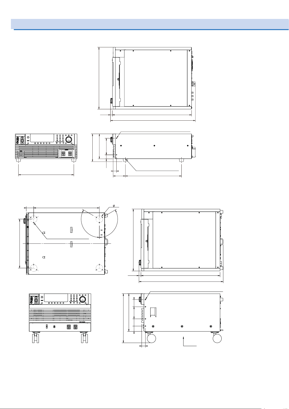
Unit: mm(inch)
Outline Drawings
■ PCR500LE
430 (16.93)
385 (15.16)
■ PCR1000LE
51.2 (2.02) 457 (17.99)
12 M6 screw holes,
max. depth 10 mm (0.39 ”)
340 (13.39)
MAX 195 (7.68)
120 °
(0.79)
173 (6.81)
115 (4.53)
27.5
(1.08)
23.2
(0.91)
550 (21.65)MAX 20
MAX 600 (23.62)
4 M4 screw holes, max. depth 10 mm (0.39 ”)
4 M4 screw holes,
max. depth 10 mm (0.39)
390 (15.35)
85 (3.35)
48 (1.89)
120 °
430 (16.93)
550 (21.65)
MAX 595 (23.43)
A arrow
Unit: mm(inch)
A-arrow caster screw position diagram
MAX 20
(0.79)
50
(1.97)
262 (10.31)
84
(3.31)
MAX 345 (13.58)
50
(1.97)
37
(1.46)
8 M4 screw holes, max. depth 10 mm (0.39 ”)
26 (1.02)
■ PCR2000LE
86 PCR-LE series
Page 87
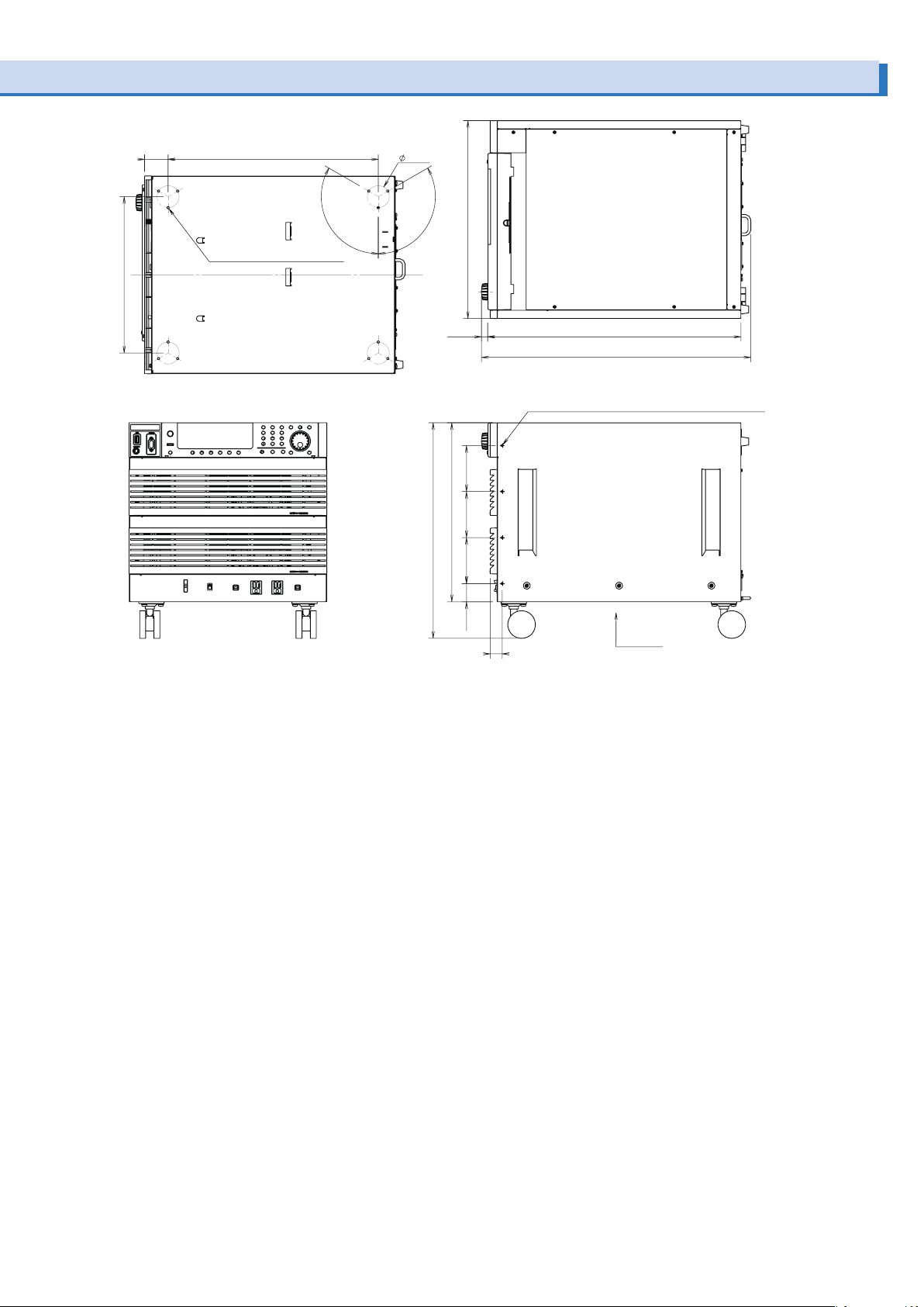
51.2 (2.02) 457 (17.99)
48 (1.89)
340 (13.39)
120 °
12 M6 screw holes,
max. depth 10 mm (0.39 ”)
A-arrow caster screw position diagram
430 (16.93)
120 °
MAX 20
(0.79)
100
(3.94)
389 (15.31)
100
(3.94)
MAX 475 (18.70)
100
(3.94)
45.5
(1.79)
550 (21.65)
MAX 595 (23.43)
8 M4 screw holes, max. depth 10 mm (0.39 ”)
26 (1.02)
A arrow
Unit: mm(inch)
PCR-LE series 87
Page 88
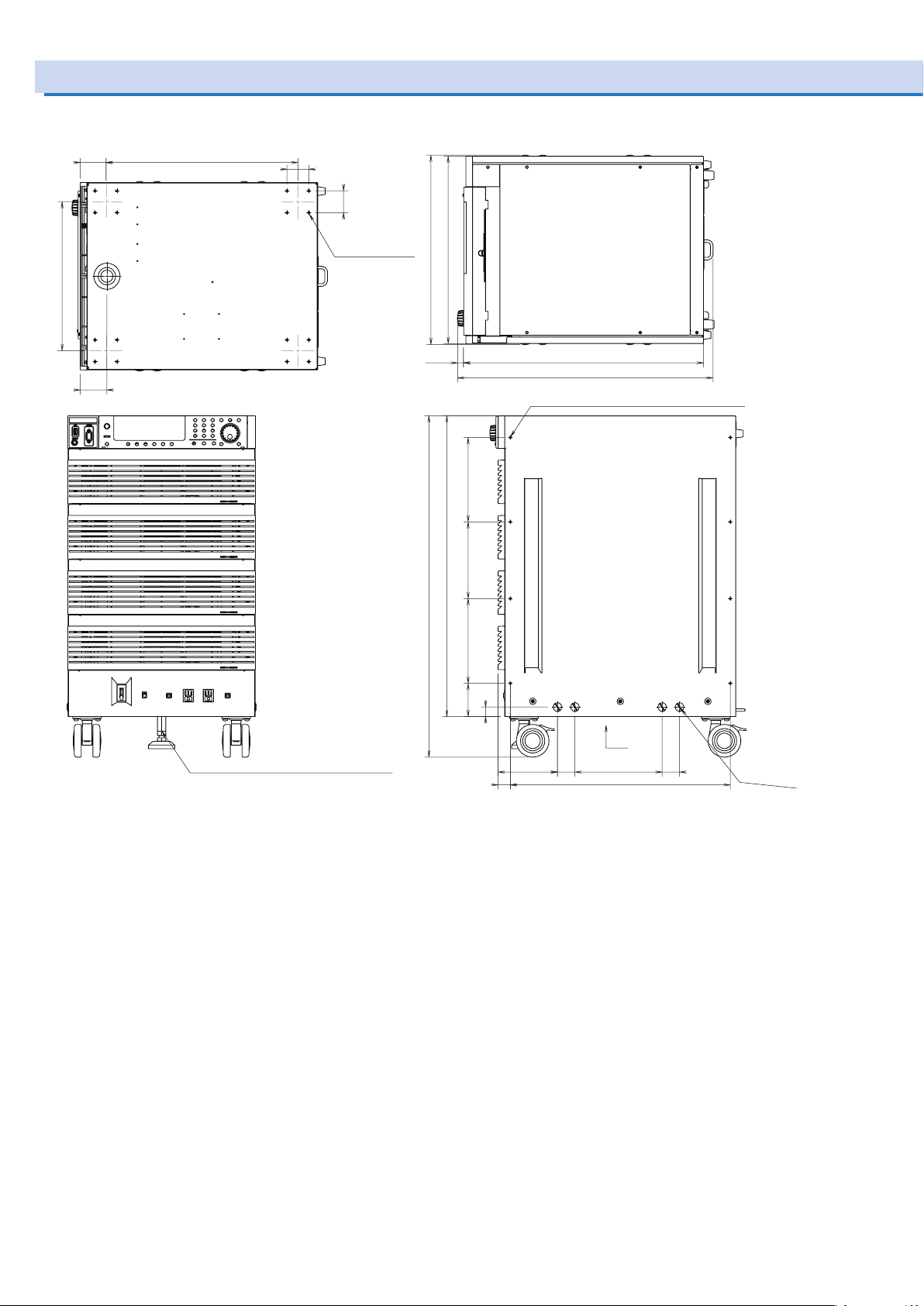
8 M10 screw holes,
59.2
440 (17.32)
342 (13.46)
Unit: mm(inch)
Outline Drawings (Cont.)
■ PCR3000LE/ PCR4000LE
(2.33)
61.2
(2.41)
A-arrow caster screw position diagram
50
(1.97)
50
(1.97)
16 M6 screw holes,
max. depth 10 mm
(0.39 ”)
430 (16.93)
MAX 445 (17.52)
MAX 20
(0.79)
690 (27.17)
MAX 785 (30.91)
550 (21.65)
MAX 595 (23.43)
16 M4 screw holes, max. depth 10 mm (0.39 ”)
176.5(6.95) 195 (7.68)
M12 screw hole, max. depth 35 mm (1.38 ”)
76.5(3.01) 195(7.68)
22
(0.87)
26
(1.02)
140.2
(5.52)
40
(1.57)
A arrow
200 (7.87)
508.5 (20.02)
40
(1.57)
max. depth
10 mm (0.39 ”)
88 PCR-LE series
Page 89

■ PCR6000LE
8 M10 screw holes,
440 (17.32)
(2.33)
342 (13.46)
Unit: mm(inch)
59.2
61.2
(2.41)
50
(1.97)
A-arrow caster screw position diagram
16 M6 screw holes,
max. depth 10 mm (0.39 ”)
50
(1.97)
430 (16.93)
MAX 445 (17.52)
MAX 20
(0.79)
250 (9.84)257.5(10.14)250 (9.84)76.5
550 (21.65)
MAX 595 (23.43)
16 M4 screw holes, max. depth 10 mm (0.39 ”)
M12 screw hole, max. depth 35 mm (1.38 ”)
MAX1040
944 (36.17)
(3.01)
22
(0.87)
26 (1.02)
140.2
(5.52)
(1.57)
A arrow
200 (7.87)40
508.5 (20.02)
40
(1.57)
max. depth
10 mm (0.39 ”)
PCR-LE series 89
Page 90

Outline Drawings (Cont.)
8 M10 screw holes,
16 M6 screw holes,
342 (13.46)
Unit: mm(inch)
■ PCR9000LE
(2.33)
61.2
(2.41)
440 (17.32)59.2
A-arrow caster screw position diagram
(1.97)
50
max. depth 10 mm
(0.39 ”)
50
(1.97)
MAX 445 (17.52)
(0.79)
195 (7.68)
430 (16.93)
550 (21.65)MAX 20
MAX 595 (23.43)
28 M4 screw holes, max. depth 10 mm (0.39 ”)
M12 screw hole,
max. depth 35 mm (1.38 ”)
195 (7.68)195 (7.68)195 (7.68)
1325 (52.17)
MAX 1420 (55.91)
195 (7.68)
195 (7.68)
76.5
(3.01)
22
(0.87)
(1.02)
140.2
(5.52)
40
(1.57)
A arrow
200 (7.87) 40
508.5 (20.02)26
(1.57)
max. depth
10 mm (0.39 ”)
90 PCR-LE series
Page 91
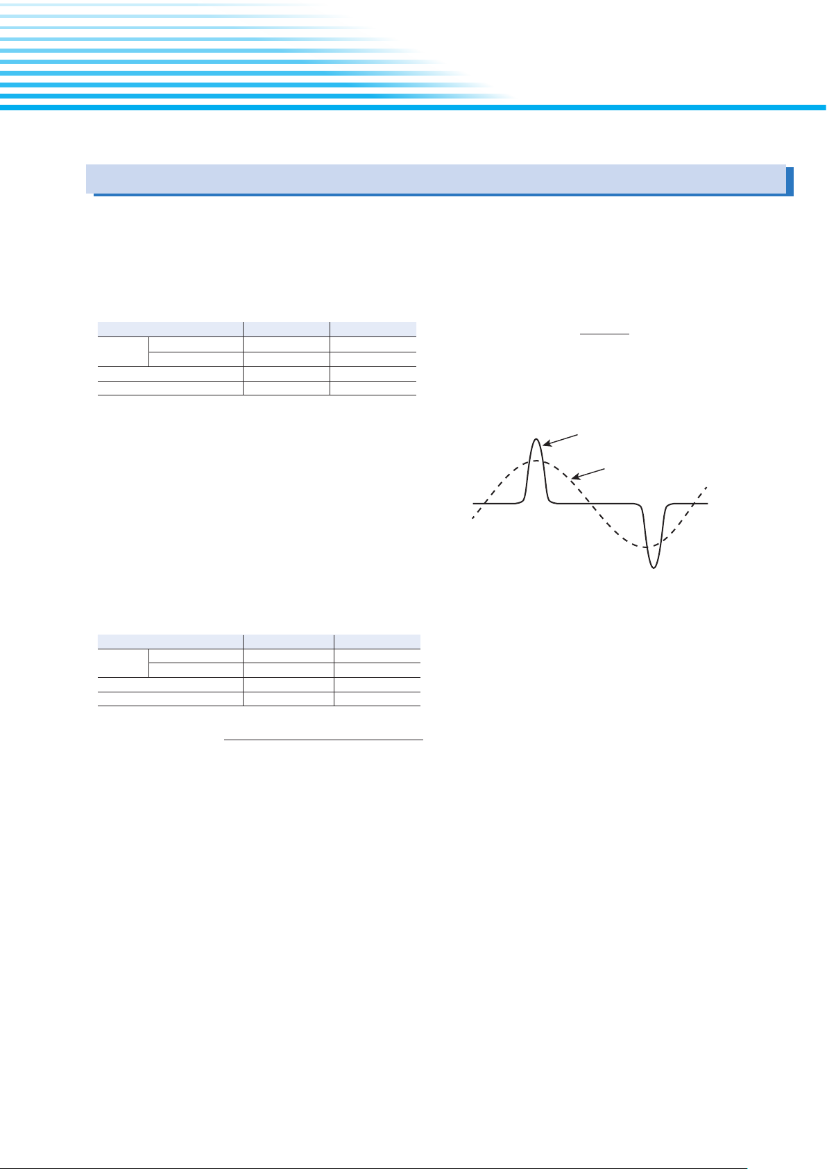
Glossary
Rated output capacity [VA]
Rated maximum output current =
Voltage at 100 % of the output voltage ratio [V]*
Peak value
Only when crest factor =
4
Rms value
Capacitor-input rectifier load
- Appendix -
Rated output capacity
This is the maximum output power capacity (in VA) that can be
supplied continuously in the following ranges. For example, this
is 1 kVA on the PCR1000LE.
In DC mode, this value is 70 % of the value in AC mode.
AC mode DC mode
Output
voltage
Load power factor 0.8 to 1.0 NA
Output frequency 0 Hz to 999.9 Hz NA
Rated output current
This is the maximum continuous output current (rms value).
(Unit: A.)
The rated output current requires derating (reduction), which is
performed according to the output conditions (output voltage,
frequency, and load power factor).
Rated maximum output current
This is the maximum rms output current (in A) that can be supplied continuously in the following ranges. For example, this is
1 kVA on the PCR1000LE.
In DC mode, this value is 70 % of the value in AC mode.
Output
voltage
Load power factor 0.8 to 1.0 NA
Output frequency 40 Hz to 999.9 Hz NA
Output L range 100 V to 150 V 100 V to 212 V
Output H range 200 V to 300 V 200 V to 424 V
AC mode DC mode
Output L range 100 V 100 V
Output H range 200 V 200 V
Maximum peak current (AC mode)
This is the maximum continuous output current (peak value
in Apeak) that the PCR-LE Series can supply when using a
capacitor-input rectifier load.
Maximum peak current = rated maximum output current (rms) × 4
≤
Output voltage: 100 V to 150 V (for output L range)
200 V to 300 V (for output H range)
Output frequency: 40 Hz to 999.9 Hz
Resistive load
Maximum instantaneous current (DC mode/ AC+DC
mode)
This is the maximum instantaneous output current (peak current in Apeak) that can be supplied to the load in DC mode or
AC+DC mode.
Maximum instantaneous current = Rated maximum output
current × 3.6
*: See p. 91,Output L range is 100 V, and output H range
200 V.
Instantaneous peak currenst (AC mode)
This is the maximum instantaneous output current (peak current in Apeak) that can be supplied to the load in AC mode.
This depends on the output range, voltage setting, and instantaneous output voltage.
The instantaneous peak current near the peak value of the
instantaneous output voltage is four times the rated maximum
output current (maximum peak current), but it decreases in accordance with the reduction in the absolute value of the instantaneous output voltage.
Figs. 10 and 11 (p. 95) show “Instantaneous output voltage
versus instantaneous peak current ratio” for the representative
voltage settings of each range.
Instantaneous peak current ratio
This is the instantaneous peak current as a percentage where
the rated maximum output current is 100 %.
Output current ratio
This is the output current as a percentage where the rated
maximum output current is 100 %.
PCR-LE series 91
Page 92
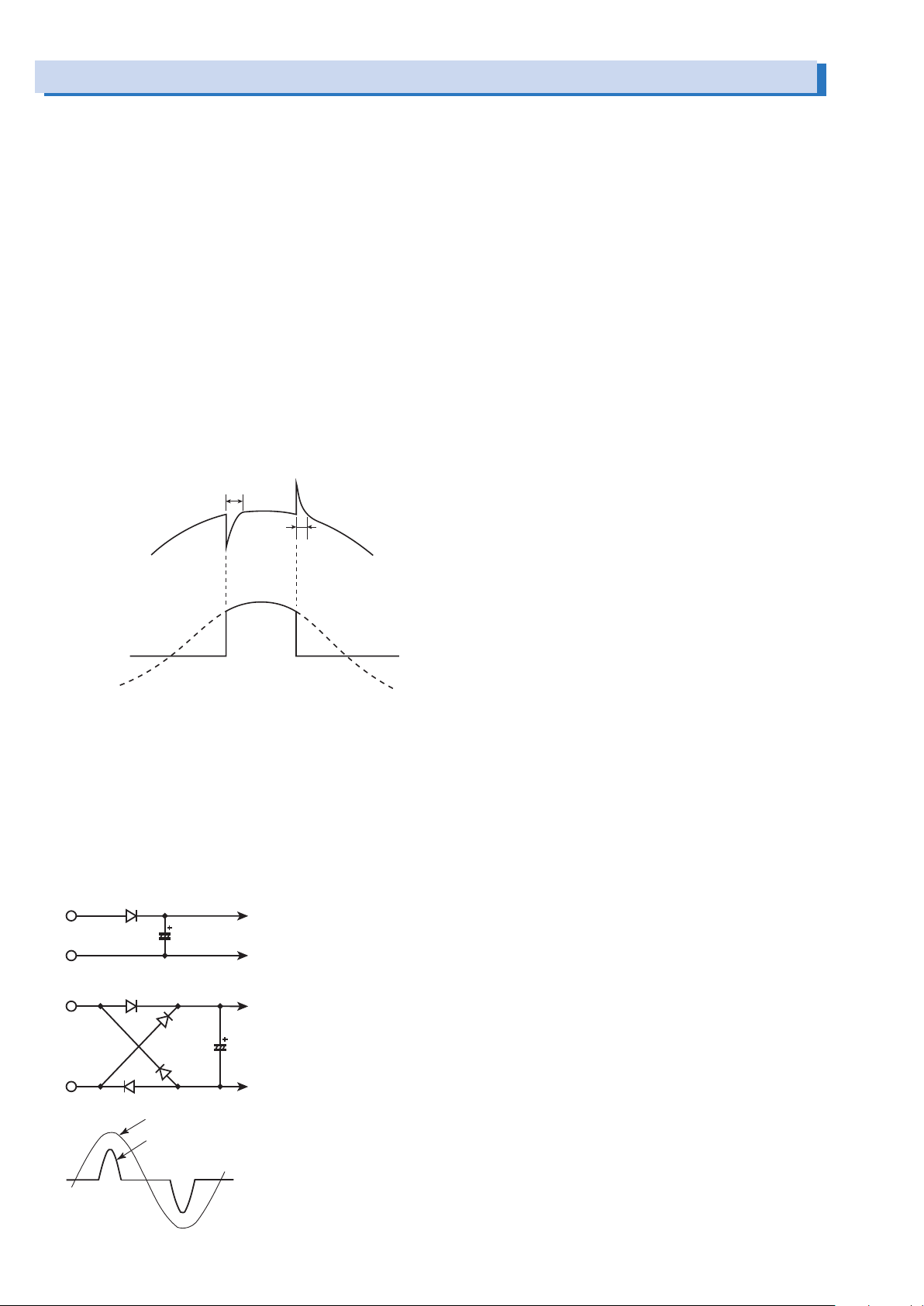
Glossary (Cont.)
Output voltage waveform
Output current waveform
(t: µs)
Input To the internal circuit
To the internal circuitInput
Output voltage ratio
This is the output voltage as a percentage where 100 V for the
output L range or 200 V for the output H range is 100 %.
Output voltage waveform distortion ratio
This is the total harmonic distortion (in %) of the output voltage
waveform when the output voltage is between 80 V and 150 V
(for output L range) or between 160 V and 300 V (for output H
range) and the load power factor is 1.
Output voltage response speed
This is the time duration defined by the output voltage change
exceeding 10 % of the total change and then returning back to
10 % or less of the total change when the output current ratio
has changed from 0 % to 100 % under the following conditions:
the output voltage is 100 V (for output L range) or 200 V (for
output H range) and the load power factor is 1 (in AC mode).
(The unit is µs.)
(t: µs)
Derating
"Derating" means "reducing." In general, this refers to using a
device at reduced maximum rated values (such as the voltage
and the current) depending on the ambient conditions (such as
the temperature and load).
Voltage dip
This refers to situations in which the voltage in a commercial
power line drops momentarily due to the effects of lightning
and other similar phenomena.
Generally, these voltage drops last for several tens of milliseconds to several hundreds of milliseconds, and the voltage
drops by 20 % to 80 %.
Capacitor-input rectier load (circuit)
This is a load whose rectifier circuit part is constructed as
shown below. The rectifier circuit is used to convert the input
AC voltage into the DC voltage that the device needs to operate.
The peak input current is normally approximately two to four
times the rms value. The conduction angle (the period that
the current is flowing for) centered on the peak output voltage
(phase angle of 90 deg or 270 deg) is approximately 20 deg to
90 deg.
Input voltage
Input current
92 PCR-LE series
Page 93

Operating Characteristics
Input current (A)
Output current ratio (%)
Input voltage : Single-phase two-wire input (1P2W): 200 V
Output voltage ratio (%)
Input current (A)
:
Output current versus input current and efciency characteristics(typical values in AC mode)
The output current ratio is a percentage where 100 % represents the maximum rated output current.
1P2W3P3W3P4W
PCR9000LE
PCR6000LE
PCR9000LE
PCR6000LE
PCR6000LE
PCR4000LE
PCR3000LE
PCR2000LE
PCR1000LE
30
20
10
30
20
10
20
8
15
6
10
4
5
2
0
0
0
40
30
20
10
60
30
45
20
30
10
15
0
0
0
50
15
10
40
30
20
5
10
0
0
20
10
0
Output voltage versus input current and efciency characteristics (typical values in AC mode)
(the value is two times this characteristic
when the voltage is 100 V of input current)
Three-phase three-wire input (3P3W): 200 V (Line voltage)
Three-phase four-wire input (3P4W):
230 V (Phase voltage)/ 400 V(Line voltage)
Output frequency : 50 Hz (approximately the same when the
frequency is in the range of 40 Hz to 999.9 Hz)
PCR500LE
Output voltage ratio : 100 %
Load power factor : 1
Ambient temperature : 25℃
5
4
3
2
1
0
0 20 40 60 80 100
Efficiency
Input current
70
60
50
40
30
Efficiency (%)
20
10
0
The output voltage ratio is a percentage where 100 % represents an output voltage of 100 V (output L range) or 200 V (output H
range).
Single-phase two-wire input (1P2W): 200 V
Input current
Efficiency
70
60
50
40
30
Efficiency (%)
20
10
0
PCR9000LE
PCR6000LE
30
20
15
20
10
10
5
0
0
PCR9000LE
50
30
40
20
30
20
10
10
0
0
PCR6000LE
PCR6000LE
40
60
30
45
20
30
10
15
0
0
Input voltage
1P2W3P3W3P4W
PCR4000LE
PCR3000LE
PCR2000LE
PCR1000LE
10
20
30
8
15
20
10
0
10
6
4
5
2
0
0
(the value is two times this characteristic
when the voltage is 100 V of input current)
Three-phase three-wire input (3P3W):
200 V (Line voltage)
Three-phase four-wire input (3P4W):
230 V (Phase voltage)/ 400 V (Phase voltage)
Output frequency : 50 Hz (approximately the same when the
PCR500LE
frequency is in the range of 40 Hz to 999.9 Hz)
Output current : Rated value (load power factor 1)
Ambient temperature : 25 °C
5
4
3
2
1
0
0 20 40 60 80 100
PCR-LE series 93
Page 94
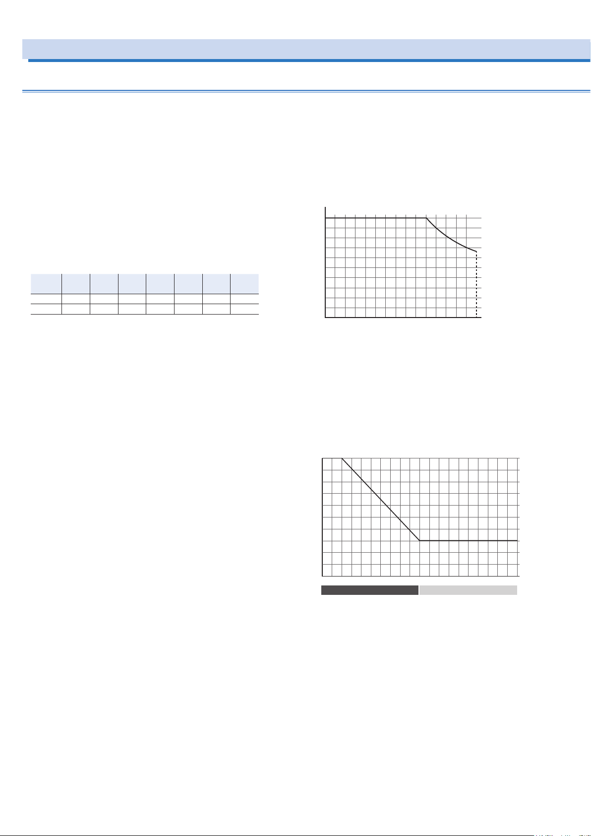
About the output and the load
Output voltage ratio (%)
Output current ratio
( )
%
Load power factor
Output current ratio
( )
%
100
1
Rated output current in AC mod
The rated current is automatically derated (reduced) depending on the output conditions (output voltage, frequency, and
load power factor).
Output voltage ratio:
A percentage where 100 % represents an output voltage of
100 V (output L range) or 200 V (output H range).
Output current ratio:
A percentage where 100 % represents the rated maximum
output current.
Instantaneous peak current ratio:
A percentage where 100 % represents the rated maximum
output current.
Rated maximum output current:
PCR
PCR
PCR
PCR
PCR
PCR
500LE
1000LE
2000LE
3000LE
4000LE
L range 5 A 10 A 20 A 30 A 40 A 60 A 90 A
H range 2.5 A 5 A 10 A 15 A 20 A 30 A 45 A
6000LE
PCR
9000LE
• Fig.7 Output voltage ratio versus output current ratio (AC
mode)
Output current ratio [%] when the output voltage setting (ACvolt) is between 0 V and 100 V (L range) or between 0 V and
200 V (H range): 100
Output current ratio [%] when the output voltage setting
(ACvolt) is 100 V or higher (L range) or 200 V or higher (H
range): 100/ Output voltage ratio ×100
100
80
60
40
20
0
0 20 40 60 80 100 120 140 150
• Fig.8 Load power factor versus output current ratio
Output current ratio [%] when the load power factor is great-
er than 0.8: 100
Output current ratio [%] for forward power flow when the load
power factor is less than or equal to 0.8:
30 + load power factor × 70/0.8
Output current ratio [%] for reverse power flow: 30
80
60
40
20
0
Forward power flow Reverse power flow
00.2 0.20.4 0.40.6 0.60.8 0.81
94 PCR-LE series
Page 95
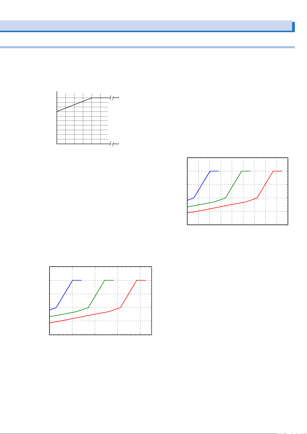
• Fig.9 Output frequency versus output current ratio
999.9
Output frequency (Hz)
Output current ratio (%)
|Instantaneous output voltage| (V)
50 Hz/60 Hz Typical value
450
50 Hz/60 Hz Typical value
Instantaneous peak current ratio (%)
Output current ratio [%] when the output frequency (Freq) is
less than 40 Hz: 70+ output frequency×30/ 40
Output current ratio [%] when the output frequency (Freq) is
greater than or equal to 40 Hz: 100
100
80
60
40
20
0
10
1
20 30
40 50
• Fig.10 Instantaneous output voltage ratio versus instantaneous peak current ratio (AC mode L range, excluding threephase three-wire output)
The instantaneous output voltage is the instantaneous value
of the output voltage waveform.
This shows the instantaneous peak current ratio in relation to
the instantaneous output voltage when the output voltage is
set to 50 V, 100 V, and 150 V.
For example, the instantaneous peak current that can be
supplied when the setting voltage is 100 V is 160 % of the
rated current (rms) when the instantaneous output voltage is
50 V and 280 % of the rated current (rms) when the instantaneous output voltage is 100 V.
During three-phase three-wire output, the instantaneous peak
current ratio is limited also by the instantaneous output voltage of other phases.
• Fig.11 Instantaneous output voltage ratio versus instantaneous peak current ratio (AC mode H range, excluding threephase three-wire output)
The instantaneous output voltage is the instantaneous value
of the output voltage waveform.
This shows the instantaneous peak current ratio in relation to
the instantaneous output voltage when the output voltage is
set to 100 V, 200 V, and 300 V.
For example, the instantaneous peak current that can be
supplied when the setting voltage is 200 V is 160 % of the
rated current (rms) when the instantaneous output voltage is
100 V and 280 % of the rated current (rms) when the instantaneous output voltage is 200 V.
During three-phase three-wire output, the instantaneous peak
current ratio is limited also by the instantaneous output voltage of other phases.
500
Setting voltage
400
300
200
100
0
0 50 100 150 200 250 300 350 400
100 V
Setting voltage
200 V
Setting voltage
300 V
|Instantaneous output voltage| (V)
500
Setting voltage
400
300
200
100
Instantaneous peak current ratio (%)
0
0 50 100 150 200
50 V
Setting voltage:
100 V
Setting voltage
150 V
PCR-LE series 95
Page 96

About the output and the load (Cont.)
Rated output current in AC mod (Cont.)
How the rated output current is determined on the PCR1000LE
The rated output current in AC mode depends on the output
conditions (output voltage, load power factor, output frequency). The rated output current under given output conditions is
the value obtained by converting the smaller of the two values:
the product of the output current ratios derived from fig. 7 (output voltage) and fig. 8 (load power factor) and the output current ratio derived from fig. 9 (output frequency).
The full scale of the load level meter of control panel is set to 1.1
times the calculated rated current or the current limit, whichever is less.
Example
If you use the PCR-LE Series under conditions that exceed
those that produce the rated output currents described below,
the protection functions may be activated, which may cause
the output voltage to drop, or turn off the output.
Example 1: The output voltage is 80 V (L range), the load
power factor is 0.6, and the output frequency is 50 Hz.
From the fig.7, the output current ratio at an output voltage of 80 V
is 100 %. - - -(a)
From the fig.8, the output current ratio at a load power factor of 0.6
is 82.5 %. - - - (b)
From the fig.9, the output current ratio at an output frequency of 50
Hz is 100 %. - - - (c)
Example 2: The output voltage is 250 V (H range), the load
power factor is 0.4, and the output frequency is 60 Hz.
From the fig.7, the output current ratio at an output voltage of 250 V
is 80 %. - - (a)
From the fig.8, the output current ratio at a load power factor of 0.4
is 65 %. - - - (b)
From the fig.9 the output current ratio at an output frequency of 60
Hz is 100 %. - - - (c)
From (a) and (b), the output current ratio at an output voltage of
250 V and a load power factor of 0.4 is
(a)×(b) = 52 % - - - - - - - - - - - - - - - - - - - - - - (d)
Because (d) is smaller than (c), the output current ratio is limited by (d). Therefore, the maximum output current ratio is 78 %.
On the PCR1000LE, the rated maximum output current for the
output H range is 5 A, so the rated output current under the
above conditions is
5×0.52 = 2.6 A
From (a) and (b), the output current ratio at an output voltage of
80 V and a load power factor of 0.6 is
(a)×(b) = 82.5 % - - - - - - - - - - - - - - - - - - - - - - - - (d)
Because (d) is smaller than (c), the output current ratio is limited by (d), which was calculated as (d). Therefore, the maximum output current ratio is 82.5 %.
On the PCR1000LE, the rated maximum output current for the
output L range is 10 A, so the rated output current under the
above conditions is
10×0.825 = 8.25 A
96 PCR-LE series
Page 97

Example 3: The output voltage is 80 V (L range), the load
power factor is 0.6, and the output frequency is 10 Hz.
From the fig.7, the output current ratio at an output voltage of 80 V
is 100 %. - - (a)
From the fig.8, the output current ratio at a load power factor of 0.6
is 82.5 %. - - - (b)
From the fig.9 the output current ratio at an output frequency of 10
Hz is 77.5 %. - - - (c)
From (a) and (b), the output current ratio at an output voltage of
80 V and a load power factor of 0.6 is
(a)×(b) = 82.5 % - - - - - - - - - - - - - - - - - - - - - - (d)
Because (c) is smaller than (d), the output current ratio is limited by (c). Therefore, the maximum output current ratio is (c) =
77.5 %.
On the PCR1000LE, the rated maximum output current for the
output H range is 5 A, so the rated output current under the
above conditions is
5×0.775 = 7.75 A
PCR-LE series 97
Page 98
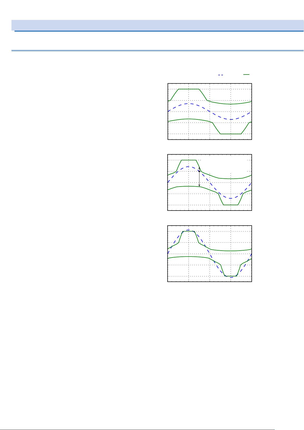
About the output and the load (Cont.)
0
1/4T 2/4 T 3/4 T
Instantaneous output voltage (V)Instantaneous output voltage (V)Instantaneous output voltage (V)
Rated output current in AC mod (Cont.)
How peak current that can be supplied is deter-
mined (for single-phase output)
As shown in figs. 10 and 11, “Instantaneous output voltage
versus instantaneous peak current ratio,” the peak current supply performance depends on the output range, voltage setting,
and instantaneous output voltage.
Figs. 12 and 13 show the range in which peak current can be
supplied (range between two solid lines) for the voltage waveforms (broken lines) at the representative voltage settings of
each range.
The instantaneous peak current near the peak value of the
instantaneous output voltage is four times the rated maximum
output current (maximum peak current), but it decreases in
accordance with the reduction in the absolute value of the instantaneous output voltage. If this range is exceeded, the protection functions of this product may be activated, which may
distort the output voltage waveform or turn off the output.
For loads through which inrush current flows, such as transformers, motors, lamps, and capacitor-input rectifier circuits,
check the current waveform, and provide adequate margin so
that the peak current supply range is not exceeded. In addition, keep the rms value of the output current from exceeding
the rated output current or in the case of reverse power flow, 30
% of the rated output current.
• Fig.12 Voltage waveform versus peak current supply range
(AC mode L range)
Voltage
Setting voltage: 50 V
200
100
0
-100
-200
0 T
Setting voltage: 100 V
200
100
0
-100
-200
0
1/4T 2/4 T 3/4 T
Peak current supply range
Peak current supply range
when the instantaneous
when the instantaneous
output voltage is 100 V
output voltage is 100 V
1/4T 2/4 T 3/4 T
50 Hz/60 Hz Typical value
Current
400
200
0
-200
-400
Instantaneous peak current ratio (%)Instantaneous peak current ratio (%)Instantaneous peak current ratio (%)
400
200
0
-200
-400
T
Setting voltage: 150 V
200
100
0
-100
-200
400
200
0
-200
-400
T
98 PCR-LE series
Page 99
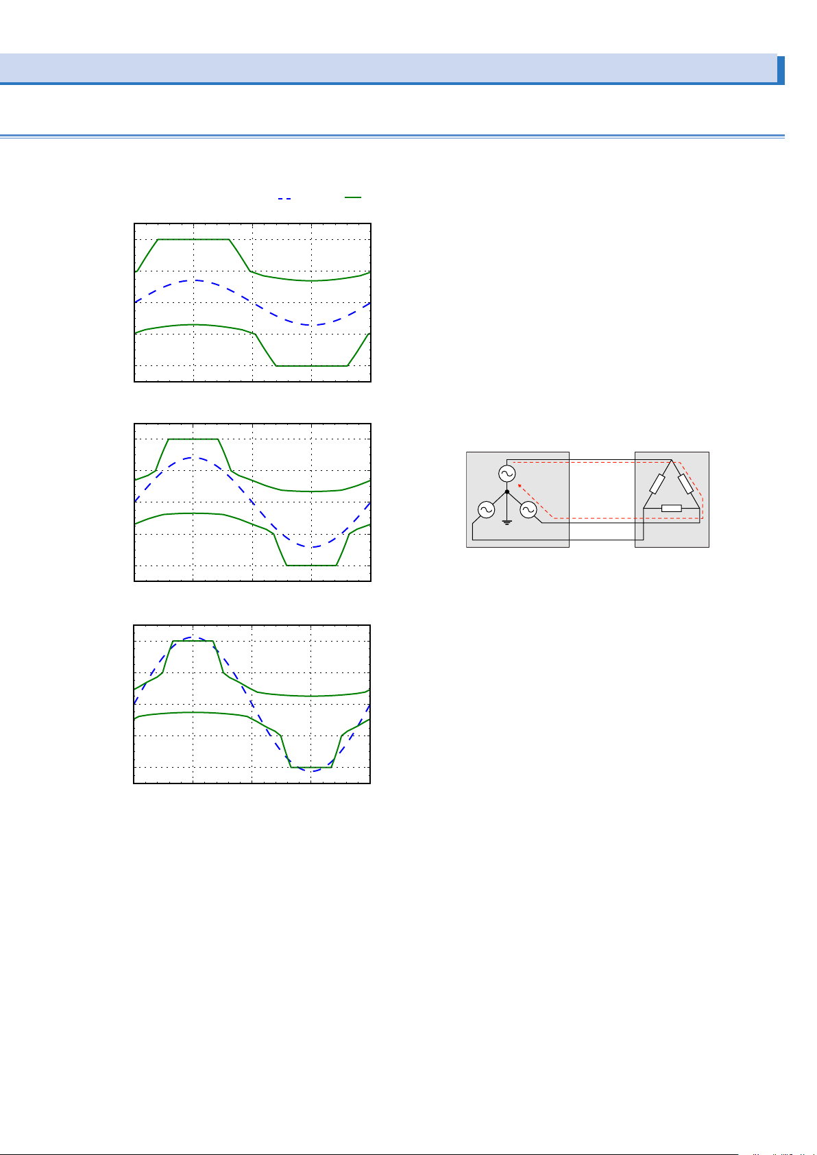
• Fig.13 Voltage waveform versus peak current supply range
T
1/4T 2/4T 3/4 T
Voltage
Current
Instantaneous peak current ratio (%)Instantaneous peak current ratio (%)Instantaneous peak current ratio (%)
PCR-LE/LE2 Load
(AC mode H range)
Setting voltage
400
200
0
-200
-400
Instantaneous output voltage (V)Instantaneous output voltage (V)Instantaneous output voltage (V)
0 T
Setting voltage
400
: 100 V
1/4T 2/4T 3/4 T
: 200 V
50 Hz/60 Hz Typical value
400
200
0
-200
-400
400
How peak current that can be supplied is deter-
mined (for three-phase output)
Also for three-phase output, the peak current supply performance depends on the output range, voltage setting, and
instantaneous output voltage as shown in fig. 10 and fig. 11,
“Instantaneous output voltage versus instantaneous peak
current ratio.”
If you are using three-phase four-wire output, read “setting
voltage” as “setting phase voltage” and “instantaneous output voltage” as “instantaneous value of phase voltage” in fig.
10 and fig. 11.
If you are using three-phase three-wire output, because the
phase voltages of the two phases are connected in series as
shown in the following figure, the instantaneous peak current
ratio is limited also by the instantaneous output voltage of the
other phase. As such, the instantaneous peak current ratio
when the instantaneous output voltage of the other phase is
near 0 V may be lower than the rating.
200
0
-200
-400
0 T
Setting voltage
400
200
0
-200
1/4T 2/4T 3/4 T
: 300 V
-400
0
200
0
-200
-400
400
200
0
-200
-400
U
N
W
V
PCR-LE series 99
Page 100

Output voltage
Rated output capacity [VA]
Rated maximum output current =
Voltage at 100 % of the output voltage ratio [V]*
About the output and the load (Cont.)
Rated output current in AC mod (Cont.)
Capacitor-input rectier loads
For electronic devices that have capacitor-input rectifier circuits
in their input, when the output voltage approaches the peak
output voltage, a peak current several times greater than the
output current rms value flows as the output current.
Output current
As shown in figs. 10 to 13, keep the maximum peak current
near the peak value of the instantaneous output voltage from
exceeding four times the rated maximum output current.
*: Output L range is 100 V, and output H range 200 V.
The output current rms should not exceed the rated output
current value calculated with the load power factor set to 1, as
explained in "Linear load".
If you use the PCR-LE Series with an output current that exceeds the rated output current (peak or rms value) specified
above, the protection functions may be activated, which may
distort the output voltage waveform or turn off the output.
You can only supply the maximum peak current described
above without any distortions when the output voltage (the setting) is fixed. If the output voltage setting is changed suddenly
(increased), the voltage and current waveforms may be distorted. Even if you are executing power line abnormality simulations or sequences, distortions may occur in the same manner
if the output voltage is changed suddenly. To supply the maximum peak current without distortions, fix the output voltage setting and then turn the output on.
Loads that generate surges
Some loads (for example, fluorescent lights) generate surges
when the voltage is applied to the load or when the voltage is
changed suddenly. When a surge occurs, the PCR-LE Series
may malfunction. For this type of load, connect a noise filter to
the output cable.
Special loads
If you connect a capacitor directly to the OUTPUT terminal
block or the OUTPUT outlets, the output waveform may be distorted. In this situation, connect the capacitor to the load side
of the output wiring.
Loads that draw an inrush current
For loads such as those listed below, when the voltage is applied to the load or when the voltage changes suddenly, an
inrush current (several times to several tens of times the normal
current) flows for several cycles to several tens of cycles of the
output frequency.
•
Transformer and slide transformer (SLIDAC) loads
When a voltage is applied to a transformer or a slide transformer, an inrush current of up to several hundreds of times
the normal current will flow for several cycles depending on
the timing that the voltage is applied or the residual magnetization in the transformer.
•
Motor and lamp loads
When a voltage is applied to a motor or a lamp, an inrush
current of several times to several tens of times the normal
current flows for several tens of cycles to several hundreds of
cycles.
•
Capacitor-input rectier loads
For electronic devices that have capacitor-input rectifier circuits in their input, if the device does not have an inrush current protection (limitation) circuit, an inrush current of several
tens to several hundreds of times the normal current flows for
several cycles.
As shown in figs. 10 to 13, for capacitor-input rectifier loads,
this product can supply maximum peak current up to four times
the rated maximum output current near the peak value of the
instantaneous output voltage.
For other loads, this product can supply maximum peak current up to 200 % of the instantaneous peak current ratio for the
specified trip time (TRIP TIM) even if the rms value of the output
current exceeds the rated output current (varies depending on
the current waveform, output voltage, output frequency, and the
like).
Examples of the instantaneous peak currents that can be supplied when TRIP is set to ENABLE, the output voltage is set to
100 V, and the output frequency is set to 50 Hz are shown in
the following table.
Load power factor
1.0 200
0.9 160
0.8 150
0.6 140
0.4 120
0.2 110
*1. The output current ratio as a percentage where 100 % represents the maxi-
mum output current of the PCR-LE Series
Instantaneous peak current ratio
(%)*1 [%]
If an inrush current that exceeds the peak currents listed above
flows, the protection circuits of the PCR-LE Series will be activated, which may distort the output voltage waveform or turn
off the output.
Particularly for inductive loads such as transformers and motors, if the protection circuit is activated and the output is
turned off, a reverse voltage exceeding the voltage setting may
be generated and appear at the output terminals.
100 PCR-LE series
 Loading...