

Page 1

Communication Interface Manual AC Power Supply PCR-MA Series
PART NO. IA005402
Apr. 2018
Communication Interface Manual
AC Power Supply PCR-MA Series
PCR500MA
PCR1000MA
PCR2000MA
PCR4000MA
KIKUSUI ELECTRONICS CORP.
1-1-3 Higashiyamata, Tsuzuki-ku, Yokohama,
224-0023, Japan
Tel: +81-45-482-6353 Fax: +81-45-482-6261
Website
http://www.kikusui.co.jp/en
Page 2

Command List
Command List
*CLS
Clears all event registers including the status byte, event status, and error queue.
*ESE
Sets the event status enable register that is counted by the event summary bit (ESB) of the
status byte.
*ESR
Queries the event status register.
*IDN
Queries the model name, serial number, and rmware version of the PCR-MA.
*LRN
Queries the command that can restore the current panel settings.
*OPC
Sets the OPC bit (bit 0) of the event status register when all the commands in standby have
been completed.
*OPT
Queries the optional interface board that are installed in the PCR-MA.
*STB
Queries the contents of the status byte register and the MSS (master summary status)
message.
*TRG
Trigger command.
*TST
Executes a self-test.
*WAI
Prevents the PCR-MA from executing subsequent commands until all operations in standby
are complete.
ABOR
Aborts operations such as change and measurement in all trigger subsystem (TRANSient/
ACQuire).
ABOR:ACQ
Aborts operations such as execute in ACQuire trigger subsystem.
ABOR:TRAN
Aborts the setting change trigger function.
DISP:AMM
Sets the measured value displayed on the lower numeric display.
*PSC
Sets whether to clear the event status enable register and the service request enable
register when the POWER switch is turned on (power-on status).
INIT:ACQ
Clears the present valid measurement data and starts a new measurement.
INIT:CONT:ACQ
*RCL
Reads the contents stored in memory.
Sets the auto continue mode of the ACQuire subsystem.
INIT:TRAN
*RST
Resets a portion of the product settings.
Starts the setting change (TRANsient) trigger function.
LXI:IDEN
*SAV
Stores the current panel settings to memory
Turns the identify display on or off.
FETC:<meas-item>/ MEAS:<meas-item>
*SRE
Sets the service request enable register.
Queries the scalar measurement data specied with <meas-item>.
OUTP
Turns the output on and off.
KIKUSUI Electronics Corp. PCR-MA Interface Manual
Page 3

Command List
OUTP:COUP
Sets the output mode.
OUTP:PON:STAT
Sets the panel settings at power-on.
OUTP:PROT:CLE
Clears alarms.
SENS:AVER
Sets the averaging period of the measured values (excluding the peak current).
SENS:CURR:HOLD
Sets the hold time of the peak current.
SENS:CURR:HOLD:CLE
Clears the peak hold of the current measurement
CURR
Sets the AC current upper limit.
CURR:OFFS
Sets the DC current upper limit.
CURR:PROT:STAT
Sets the PCR-MA acts when the current limit is exceeded.
FREQ
Set the AC output frequency.
FREQ:LIM:LOW
Sets the lower limit value of frequency.
FREQ:LIM:UPP
Sets the upper limit value of frequency.
FREQ:MODE
Sets the trigger function control of the frequency setting when INIT/INIT:TRAN and a
software trigger are sent.
FREQ:TRIG
Sets the target frequency when INIT/INIT:TRAN and a software trigger are sent.
VOLT
Sets the AC voltage.
VOLT:LIM:LOW
Sets the lower limit value of AC voltage.
VOLT:LIM:UPP
Sets the upper limit value of AC voltage.
VOLT:MODE
Sets the trigger function control of the AC voltage setting when INIT/INIT:TRAN and a
software trigger are sent.
VOLT:OFFS
Sets the DC voltage.
VOLT:OFFS:LIM:LOW
Sets the lower limit value of DC voltage.
VOLT:OFFS:LIM:UPP
Sets the upper limit value of DC voltage.
VOLT:OFFS:MODE
Sets the trigger function control of the DC voltage setting when INIT/INIT:TRAN and a
software trigger are sent.
VOLT:OFFS:TRIG
Sets the target DC voltage when INIT/INIT:TRAN and a software trigger are sent.
VOLT:RANG
Sets the voltage range.
VOLT:RANG:AUTO
Sets AUTO function of the voltage range.
VOLT:TRIG
Sets the target AC voltage when INIT/INIT:TRAN and a software trigger are sent.
STAT:OPER
Queries the event of the OPERation status register.
STAT:OPER:COND
Queries the condition of the OPERation status register.
STAT:OPER:ENAB
Sets the enable register of the OPERation status register.
KIKUSUI Electronics Corp. PCR-MA Interface Manual
Page 4

Command List
STAT:OPER:NTR
Sets the negative transition of the OPERation status register.
STAT:OPER:PTR
Sets the positive transition of the OPERation status register.
STAT:QUES
Queries the event of the QUEStionable status register.
STAT:QUES:COND
Queries the condition of the QUEStionable status register.
STAT:QUES:ENAB
Sets the enable register of the QUEStionable status register.
STAT:QUES:NTR
Sets the negative transition of the QUEStionable status register.
STAT:QUES:PTR
Sets the positive transition of the QUEStionable status register.
STAT:PRES
Resets the ENABle, PTRansition, and NTRansition filter registers of all status registers
(including sub registers) to their default values
SYST:COMM:GPIB:ADDR
Sets the GPIB address.
SYST:COMM:LAN:CONT
Queries the TCP port number used by SCPI-RAW.
SYST:COMM:RLST
Sets the operation of the PCR-MA to local or remote.
SYST:COMM:TCP:CONT
Queries the TCP port number used by SCPI-RAW.
SYST:ERR:COUN
Queries the number of unread errors in the error queue.
SYST:KLOC
Sets and releases the panel operation lock (keylock).
SYST:LOC/ SYST:REM/ SYST:RWL
This is an old style command.
SYST:OPT
Queries the option that are installed in the PCR-MA.
SYST:VERS
Queries the version of the SCPI specications to which the PCR-MA conforms.
TRIG:ACQ
Executes a software trigger for a ACQuire trigger subsystem.
TRIG:ACQ:SOUR
Sets the condition (trigger source) that determines when the ACQuire trigger subsystem
actually starting the measuremen after the PCR-MA receives the INIT:ACQ command.
TRIG:TRAN
Executes a software trigger for the TRANsient trigger subsystem.
TRIG:TRAN:SOUR
Sets the condition (trigger source) that determines when the TRANsient trigger subsystem
actually changing the setting after the PCR-MA receives the INIT:TRAN command.
TRIG:SYNC:PHAS
Sets the phase angle of the OUTPUT on.
TRIG:SYNC:SOUR
Sets the OUTPUT on phase control when OUTP ON is sent.
SYST:COMM:USB:ADDR
Queries the address information of the USB interface.
SYST:CONF:TRAC
Sets whether to display communication errors by performing a debug trace.
SYST:ERR
Reads the oldest error information or event information from the error queue.
KIKUSUI Electronics Corp. PCR-MA Interface Manual
Page 5

Introduction
Introduction
The PCR-MA series Communication Interface Manual explains the settings and commands for remotely controlling the PCR-MA series.
• USB interface (standard equipped)
• LAN interface (standard equipped)
• GPIB interface (Optional)
When the PCR-MA series is operating under remote control,the REMOTE LED on the
display on the front panel lights. To switch from remote mode to local mode from the
panel, press LOCAL.
■ Reading environment
This manual can be viewed by the following environment.
PDF Reader: Adobe Reader
■ Intended readers
This manual is written for readers with sufcient basic knowledge of how to control
instruments using a PC.
Familiarize yourself with the syntax of the SCPI commands that are used with the
product before you use them.
■ Trademarks
Microsoft and Windows are registered trademarks of Microsoft Corporation in the
United States and/or other countries.
All other company names and product names used in this manual are trademarks or
registered trademarks of the respective company.
■ Instrument Interface Standards
The PCR-MA conforms to the following standards.
• IEEE Std 488.2-1992 IEEE Standard Codes, Formats, Protocols, and Common
Commands For Use With IEEE Std 488.1-1987
• IEEE Std 488.1-1987 IEEE Standard Digital Interface for Programmable Instrumen-
tation
• Standard Commands for Programmable Instruments (SCPI) version 1999.0
• Universal Serial Bus Specication Rev 2.0
• Universal Serial Bus Test and Measurement Class Specication (USBTMC) Rev 1.0
• Universal Serial Bus Test and Measurement Class, Subclass USB488 Specication
(USBTMC-USB488) Rev 1.0
• TCP/IP Instrument Protcol Specication VXI-11
• TCP/IP-IEEE488.2 Interface Specication VXI-11.3
• 1.5 LXI Device Specication 2016
• IVI-6.1 IVI High-Speed LAN Instrument Protocol (HiSLIP) Rev 1.0
• VPP-4.3 The VISA Library 2010 Rev 5.0
■ Copyright and publication
The contents of this manual may not be reproduced, in whole or in part, without the
prior consent of the copyright holder.
The specications of this product and the contents of this manual are subject to
change without prior notice.
Copyright 2018 Kikusui Electronics Corp.
■ Firmware version of the product to which this manual applies
This manual applies to products with the following rmware version:
Ver.1.0x
KIKUSUI Electronics Corp. PCR-MA Interface Manual
Page 6
Interface Setup
Installing the VISA Library
VISA (Virtual Instrument Software Architecture) is a specication for standard software that is used to connect instruments. VISA was dened by the IVI Foundation.
A VISA library is required to use the software application. The VISA library (NI-VISA,
Keysight VISA, or KI-VISA) must be installed on the controller (Windows).
One of the VISA libraries (driver software implemented in compliance with the VISA
specications) below is necessary.
• NI-VISA by National Instruments (Ver. 5.1.1 or later)
• Keysight VISA by Keysight Technologies (Keysight IO Libraries Suite16.0 or later)
• KI-VISA Ver. 5.0.4 or later
- Note If your VISA library is an older version than that specied, you may not be able to
use it depending on the interface.
Interface Setup
The PCR-MA is equipped with USB and LAN interfaces as standard.
There is no need to switch interfaces. All interfaces can be used simultaneously.
Each interface can be set to OFF in CONFIG settings.
USB
LAN
Accessing and Operating the PCR-MA from a Web Browser (LAN interface)
GPIB (Optional)
KIKUSUI Electronics Corp. PCR-MA Interface Manual
Page 7

Interface Setup
USB
A device driver supporting USB T&M Class (USBTMC) is required to control the PCRMA through the USB interface. The USBTMC driver is automatically installed by the
VISA library.
■ USB connection
Use a standard USB cable to connect the PCR to the computer.
■ USB setting
The factory default USB setting is “USB enabled.”
For datails of CONFIG settings, see the PCR-MA user's manual.
Press CONFIG several times until interface”IntF” is displayed.
1
Turn the rotary knob to select USB"USb", and then press the CONFIG.
2
Trun the rotary knob to select ON.
3
Pressing CONFIG displays the vendor ID and product ID.
Wait at least 5 seconds, and then turn the POWER switch off and on.
4
■ USB function
Complies with USB Specication 2.0
Complies with USBTMC Specication 1.0 and USBTMC-USB488 Specication 1.0
Data rate: 480 Mbps maximum (High speed)
VID (Vender ID)
0x0B3E
PID (Product ID)
PCR500MA: 0x1050
PCR1000MA: 0x1051
PCR2000MA: 0x1052
PCR4000MA: 0x1053
■ Service request
The PCR-MA is equipped with service request and serial polling functions.
KIKUSUI Electronics Corp. PCR-MA Interface Manual
Page 8
Interface Setup
LAN
WARNING
If a network problem occurs, an unexpected dangerous voltage may oc-
cur that may cause electric shock, re, physical damage to the DUT, and
so on. If you are going to remotely control the PCR-MA from a distance,
install a Web camera or take other measures to monitor the status.
To use the LAN interface to control the PCR-MA, middleware that supports the VXI11/ HiSLIP/ SCPI-RAW protocol must be installed on the controller. The middleware
is installed automatically by the VISA library.
There is a Web browser interface to the PCR-MA embedded in the LAN interface
board. You can congure the LAN interface settings from your PC's Web browser.
For information on topics such as connecting to your corporate LAN, your IP address,
your host name, and security, contact your network administrator.
If you are using a host name (a Bonjour host name), you have to install Apple Bonjour.
■ LAN connection
Use a standard LAN cable (category 5 and straight) to connect the PCR-MA to a
network hub or router. Use a crossover cable when making a direct connection.
■ LAN setting
The factory default LAN setting is “LAN enabled, IP address assignment method:
AUTO.”
Normally set the IP address assignment method to AUTO to assign the IP address
automatically.
For datails of CONFIG settings, see the PCR-MA user’s manual.
Press CONFIG several times until interface”IntF” is displayed.
1
Turn the rotary knob to select LAN”LAn”, and then press the CONFIG.
2
Trun the rotary knob to select ON.
3
Press CONFIG several times until IP address assignment method”Adr”
4
is displayed.
The assigned IP address is displayed first and then the IP address assignment
method.
Trun the rotary knob to select AUTO.
5
Select MANUAL"MAnL" to set IP address.
Press CONFIG to select LAN reset “boot”.
6
The LAN settings are also applied by turning the power off and then back on.
Trun the rotary knob to select APPL.
7
Press ENTER.
8
WARNING
Possible damage to the equipment and electric shock. The LAN interface
can be accessed from any place on the network. If necessary, congure
the security settings. You can apply password protection for security, and
you can restrict the IP addresses to limit the hosts.
- Note The LAN interface should be shifted remotely by the command ( SYST:COM-
M:RLST). Be sure to include this command at the start of the program when you
are performing remote programming.
KIKUSUI Electronics Corp. PCR-MA Interface Manual
Page 9

Interface Setup
■ Service request
The PCR-MA is equipped with service request and serial polling functions.
■ LAN function
The PCR-MA may require an Internet connection depending on the how the PCR-MA
is accessed through a Web browser.
Complies with the LXI 1.4 Core 2011
Complies with the VXI-11/ HiSLIP/ SCPI-RAW protocol
Communication speed: Maximum 100 Mbps (Auto negotiation)
NON AUTO MDIX function
Web browser access
Instrument information, network information, display of VISA resource information,
changing network settings, security setting, Use of temporary control application
■ Resetting the LAN interface
You can use the CONFIG settings to reset the LAN interface (boot: LCI).
When reset, network settings are changed as follows.
Item Default Value
Assignment Method DHCP:ON, Auto-IP:ON, Static:OFF
DNS Server Assignment 0.0.0.0
WINS Server Assignment 0.0.0.0
Enable Dynamic DNS Enable
Enable mDNS Enable
Enable NetBIOS Over TCP/IP Enable
Accessing and Operating the PCR-MA from a Web Browser (LAN interface)
You can use the LAN interface to congure detailed settings from a Web browser on
your PC. Use latest version of browser.
The Web site's URL is dened by adding "http://" in front of the PCR-MA's IP address.
When you are using a VISA library, a function is available that enables the application
program (such as National Instruments NI-MAX, Keysight Connection Expert, and Kikusui KI-VISA Instrument Explorer) to retrieve the VXI-11 measuring instrument. This
function is provided by VISA vendors. You can access the PCR-MA by clicking on the
hyperlink that is provided in the retrieval results.
You can also check the IP address with CONFIG and then directly enter the URL in
the browser’s address bar.
(Example) When the IP address is 169.254.7.8
http://169.254.7.8
To also reset the Hostname and Description, use the Web browser interface.
KIKUSUI Electronics Corp. PCR-MA Interface Manual
Page 10
Interface Setup
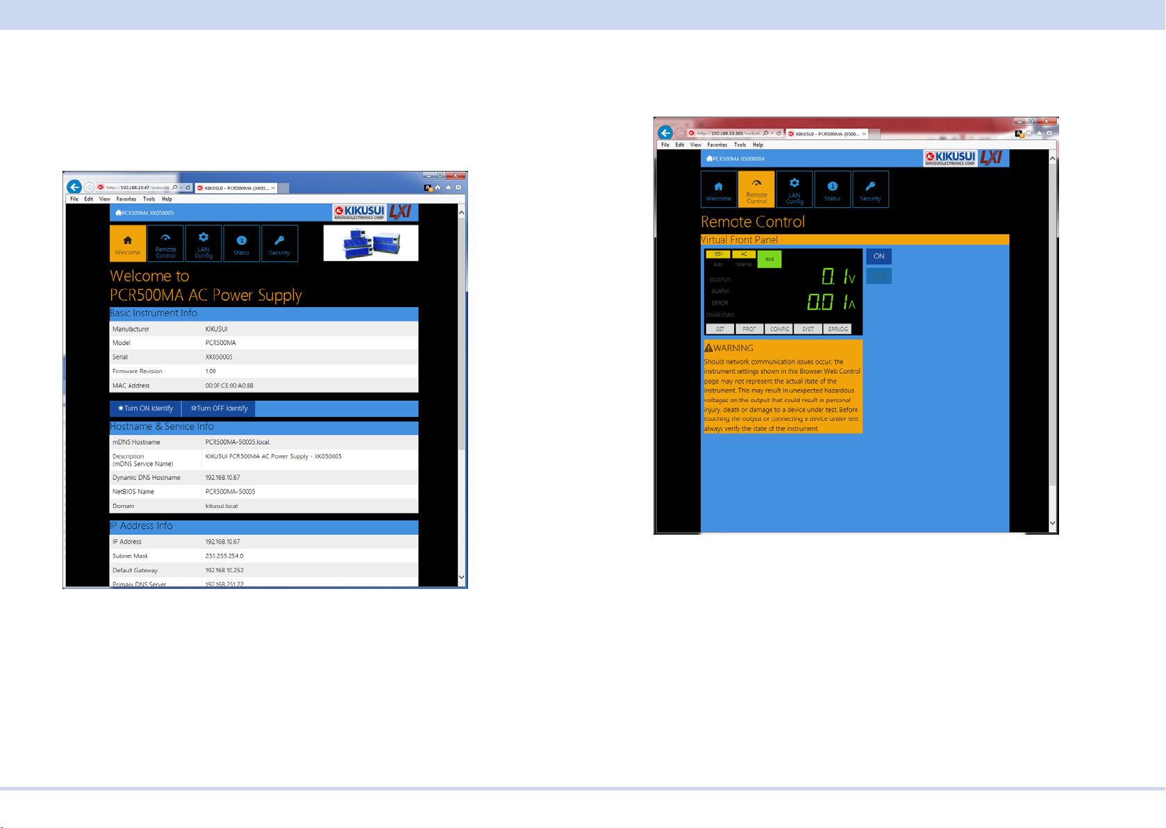
■ WELCOME page
When you access the PCR-MA from a Web browser, the WELCOME page is displayed rst.
The instrument information, network information, and VISA resource (I/O resource)
information appear on the display. Click items in the navigation menu to move to the
other pages.
■ Remote Control page
You can remotely control the PCR-MA from a browser. The various buttons have the
same functions as those on the front panel of the PCR-MA.
KIKUSUI Electronics Corp. PCR-MA Interface Manual
Page 11
Interface Setup
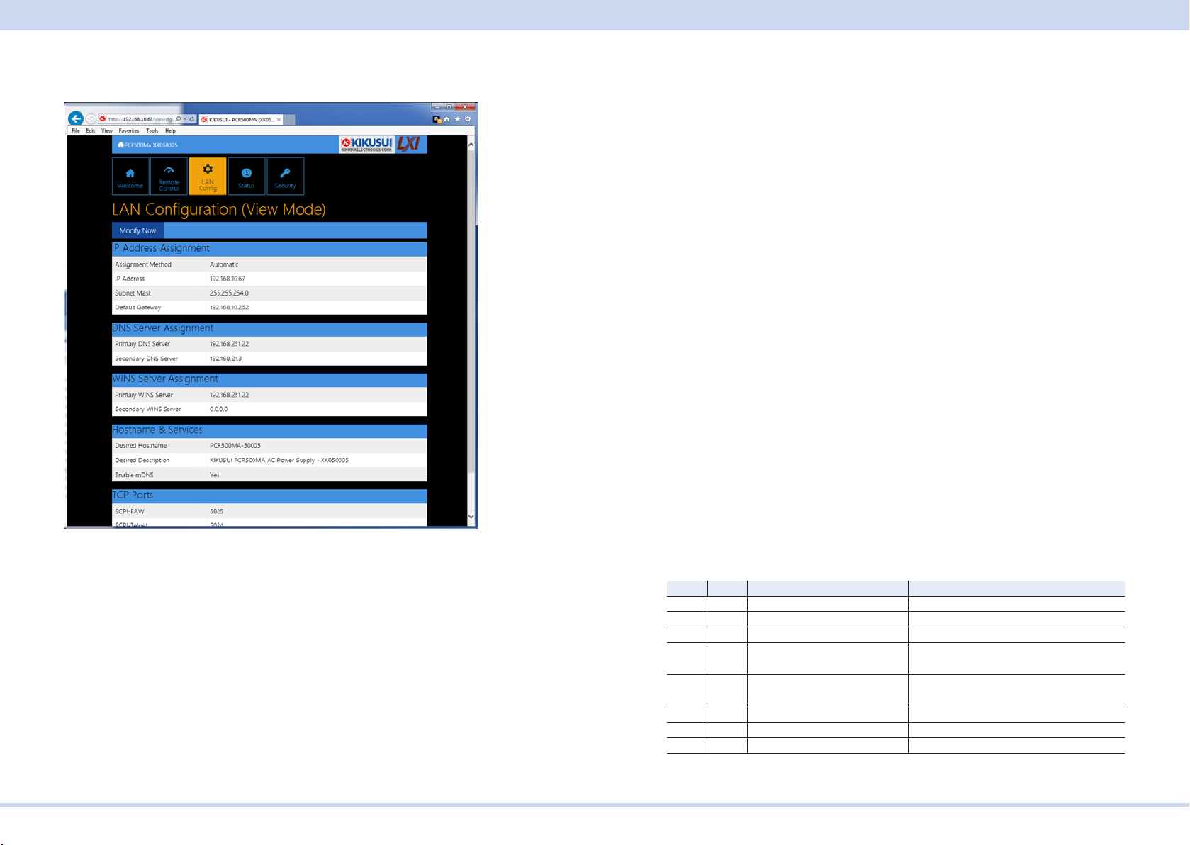
■ LAN Cong page
You can display (View Mode) and change (Modify Mode) the network settings.
IP Address Assignment
You can set the IP address. You can choose between automatic assignment and
assignment of a xed address.
In the case of automatic assignment of IP address, we recommend using the DHCP
server function using a router as far as possible.
If the DHCP server function is not used, it takes about 60 seconds until determination that address assignment with DHCP has failed. Then, an address between
169.254.0.0 to 169.254.255.255 is assigned by link local address (Auto-IP).
DNS Server Assignment
Sets the address of the DNS server.
WINS Server Assignment
Sets the address of the WINS server.
Hostname & Services
You can set the host name and so on. If you set the host name, you can use it in
place of the IP address to access the LAN interface. Normally, we recommend that
you select “Enable Dynamic DNS”, “Enable mDNS”, and “Enable NetBIOS Over TCP/
IP”.
If you leave the Hostname and Description boxes empty and click “Apply,” the host
name will be created from the model name and serial number.
TCP Ports (View Mode)
The number of the TCP port in use is displayed. You cannot change the port number.
Reset and factory default settings
Clicking Reset and Default changes the network settings change as follows.
Navigation (View Mode)
Modify Now: Goes to the network setting item editing screen (Modify Mode).
Navigation (Modify Mode)
Undo: Returns the edited contents to the state before editing.
Apply: Applies the edited contents.
Reset: Resets the network settings.
Default: Returns the network settings to the factory default settings.
Back to View Mode: Goes to the network setting item viewing screen (View Mode).
KIKUSUI Electronics Corp. PCR-MA Interface Manual
The items with an X mark are returned to their default values.
Reset Default Item Default Value
X X Assignment Method DHCP:ON, Auto-IP:ON, Static:OFF
X X DNS Server Assignment 0.0.0.0
X X WINS Server Assignment 0.0.0.0
X Desired Hostname <Model name> - <Last 5 digits of serial
number>
X Desired Description KIKUSUI <Model name> AC power supply
- <Serial number>
X X Enable Dynamic DNS Enable
X X Enable mDNS Enable
X X Enable NetBIOS Over TCP/IP Enable
Page 12
Interface Setup
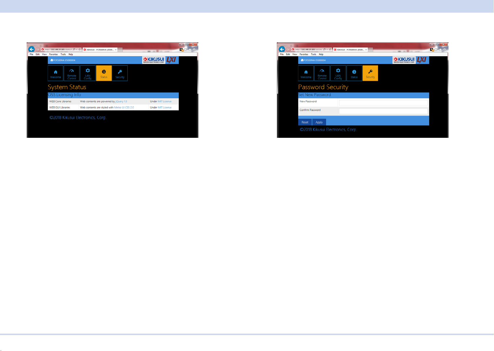
■ Status page
Displays the license information of the open-source software.
■ Security page
You can set and change the password for the Web browser interface here.
When a password has been set, that password is required in order to use the follow-
ing functions.
Remote control from Remote Control page
Editing of LAN Conguration page
Changing/deleting the password
Set New Password
Enter the password.
You can use alphanumeric characters, hyphens, and underscores for the password.
15 characters maximum. The rst character should be an alphabetical character. The
maximum password length is 15 characters.
Changing/deleting the password
After the password has been set, the screen for changing the password appears
when you enter the password.
To change the password, enter the present password in “Current Password”, enter
the new password in “New Password”and “Conrm Password”, and then click “Apply”.
To disable password protection, enter the present password in “Current Password”,
leave “New Password”and “Conrm Password” blank, and click “Apply”.
If you forget the password
If you forget the password, reset the LAN interface setting in the CONFIG settings or
initialize the PCR-MA to its factory default settings.
For datails of CONFIG settings, see the PCR-MA user's manual.
KIKUSUI Electronics Corp. PCR-MA Interface Manual
Page 13

Overview of Command
GPIB (optional)
This interface is valid only when the optional GPIB interface board is installed.
■ GPIB connection
Use a standard IEEE488 cable to connect the PCR-M to the computer.
■ GPIB conguration
Press CONFIG several times until interface”IntF” is displayed.
1
Turn the rotary knob to select GPIB”488”, and then press the CONFIG.
2
Trun the rotary knob to select ON.
3
Press CONFIG to select the GPIB address setting “Adr”.
4
Turn the rotary knob to set the GPIB address.
5
Wait at least 5 seconds, and then turn the POWER switch off and on.
6
■ Service request
Service request and serial polling functions are implemented.
Overview of Command
The information that is exchanged between the controller (PC) and the device (PCRMA series) is called a message.
The PCR-MA uses the SCPI language for the messages.
There are two types of messages, commands that are sent from the PC to the PCRMA and responses that are sent from the PCR-MA to the PC.
Command Hierarchy
SCPI commands are ASCII-based commands designed for test and measurement
devices. The command hierarchy is structured around the common root or node,
which is the construction block of the SCPI subsystem. A command consists of a
program header, parameters, and punctuation.
The hierarchy is explained using the SOURce subsystem as an example.
Program header Parameter Hierarchy of node
SOUR: Root node
FREQ Second level
:LIM Third level
:UPP <numeric> Fourth level
:LOW <numeric> Fourth level
VOLT Second level
:RANGE Third level
:UPP <numeric> Fourth level
:AUTO <boolean> Fourth level
A higher node is separated from a lower node using a colon (:).
■ GPIB function
Function Subset Description
Source handshaking SH1 Full capability
Acceptor handshaking AH1 Full capability
Talker T6 Function available
Listener L4 Function available
Service request SR1 Full capability
Remote local RL1 Full capability
Parallel polling PP0 No capability
Device clear DC1 Full capability
Device trigger DT1 Full capability
Controller C0 No capability
Electrical interface E1 Open collector driver
KIKUSUI Electronics Corp. PCR-MA Interface Manual
Page 14
Overview of Command
Command Syntax
This manual denotes SCPI commands using the following format.
MEASure[:SCALar]:CURRent:DC? {<numeric>|MINimum|MAXimum}
SCPI commands can be issued using the short form. The short form of a SCPI command is the section of the command written in uppercase.
SCPI commands can be sent in the long form or short form. Since SCPI commands
are not case-sensitive, CURR, Curr, and curr are all accepted as the short form of
CURRent. In the long form, CURRENT, Current, and current are all acceptable.
• A space is required between the program header section and the parameter sec-
tion.
• Multiple parameters, when available, are concatenated using commas.
• Commands are concatenated using semicolons (compound command).
VOLTage:OFFSet:MODE STEP;TRIGgered 48
In the second command, VOLTage:OFFSet is omitted. This is because the path is set
to VOLTage:OFFSet by the rst command VOLTage:OFFSet:MODE.
This compound command is the same as entering the following commands.
VOLTage:OFFSet:MODE STEP
VOLTage:OFFSet:TRIGgered 48
An error occurs if a node that is not dened in the current path is designated.
Commands of different subsystems can be concatenated using a colon and a semicolon together.
SOURce:CURRent MINimum;:MEASure:CURRent:AC?
This compound command contains two root nodes, SOUTce and MEASure.
When the second or subsequent command starts with a colon, the path specied by
the previous command is cleared.
• The maximum number of characters that can be transmitted in a single line is 128.
■ Special symbols
Special symbols used in this manual to describe SCPI commands are dened below.
• Characters and numbers delimited by "|" in braces indicate that one of the items is
to be selected.
Do not include the braces in the actual program.
• The characters <> indicate program data.
Do not write <> in the actual program.
• Brackets indicate option data.
When option data is not sent with the program, the default value is applied.
Do not write [ ] in the actual program.
■ Queries
The device settings or status can be queried.
To make a query, add a question mark at the end of the program header section.
If a query has parameters, enter a space after the question mark followed by the
parameters.
CURRent? MIN
Response
A response returned as an answer to a query. It is a message that is always sent from
the device to the PC. The status of the device or measured values are transmitted to
the PC.
- Note When transmitting two queries in separate lines, read the response to the rst
query before transmitting the second line.
■ Program terminator
All commands must be terminated using a valid terminator.
The available terminators (reception and transmission) is LF (line feed, ASCII 0x0A).
Either one can be used as a terminator.
When a command string is terminated, the path is reset to the root level.
- Note CR (ASCII 0x0D) is not a terminator.
KIKUSUI Electronics Corp. PCR-MA Interface Manual
Page 15

Overview of Command
■ Common commands
The IEEE-488.2 and SCPI standards contain a set of common commands for reset,
self-test, and other functions. These common commands always start with an aster-
isk. The commands may have one or multiple parameters.
Parameters
The parameter format of SCPI is derived from the program parameter format dened
in IEEE 488.2.
The representation system of the program data that is used on the PCR-MA is indicated below.
■ Non-numeric parameters
Character string data (String)
Used when a series of ASCII characters are requested.
Be sure to enclose a string in single or double quotation marks. The start and end
quotation marks must match.
DISPlay:AMMeter "AVG"
If you wish to use a quotation mark as a part of the string, enter two quotation marks
consecutively (with no characters in between).
Character data
Character data is used when only a limited number of values are available for the
program setting. Responses are returned in the short form.
TRIGger:SOURce {BUS|IMMediate}
Boolean data
Boolean data expresses a 1 or 0 condition or an ON or OFF condition. Responses
are returned as 1 or 0
OUTPut {ON|OFF|1|0}
■ Numeric parameters
NR1
Represents an integer.
Details are given in the IEEE 488.2 Standard Digital Interface for Programmable
Instrumentation.
If a 0 is returned in the response data, it is returned as +0.
NR2
Represents a real number (oating point).
Details are given in the IEEE 488.2 Standard Digital Interface for Programmable
Instrumentation.
NR3
Represents a real number (exponential).
Details are given in the IEEE 488.2 Standard Digital Interface for Programmable
Instrumentation.
The value +3.80000E+02 is returned for the response data 380. The number of digits
to the right of the decimal is 5.
NRf
NRf is a generic term that includes NR1, NR2, and NR3.
Numeric
A numeric parameter such as a decimal point, optional prex, or measurement unit.
The syntax as a numeric representation is the same as NRf.
MINimum and MAXimum are available as substitutes for declaring certain values.
Units such as V, A, and W can also be used in a numeric parameter.
■ Special form numeric parameters
The special form numeric parameters MINimum and MAXimum can be used as
substitutes for limit values when the parameter is numeric. In the example below, the
current limit is set to the minimum value.
SOURce:CURRent MINimum
Queries can be used to inquire the minimum and maximum values for most parameters.
SOURce:CURRent? MAX
SOURce:CURRent? MIN
KIKUSUI Electronics Corp. PCR-MA Interface Manual
Page 16

IEEE488.2 Common Commands
■ Measurement units
The default measurement units are listed below. Commands are accepted even if
measurement units are not specied.
•V (voltage) •A (current) •W (wattage) •VA (apparent power)
•VAR (reactive power) •DEG (degree) •HZ (frequency)
The following optional prexes are supported. If you use optional prexes, specify the
measurement unit.
•M (milli) •K (kilo) •U (micro)
- Note -
• The unit symbols in the International System of Units contain lowercase characters. The IEEE standard uses uppercase characters. SCPI commands are not
case sensitive.
• Commands are accepted whether or not measurement units are specied.
• To enter “µ” in the data, use “U” instead.
IEEE488.2 Common Commands
*CLS
Clears all event registers including the status byte, event status, and error queue.
Clears the operation complete standby that was created by the *OPC or *OPC? com-
mand.
Command
*CLS
KIKUSUI Electronics Corp. PCR-MA Interface Manual
Page 17

IEEE488.2 Common Commands
*ESE
Sets the event status enable register that is counted by the event summary bit (ESB)
of the status byte.
Command
*ESE <NRf>
*ESE?
Parameter
Value: 0 to 255
Response: NR1
(Example) When *ESE 16 is transmitted, bit 4 of the event status enable register is
set. Each time the execution error bit (bit 4) of the event status register is set, the
summary bit (ESB) of the status byte is set.
*ESR
Queries the event status register.
Registers that are read are cleared.
Command
*ESR?
Response: NR1
KIKUSUI Electronics Corp. PCR-MA Interface Manual
Page 18

IEEE488.2 Common Commands
*IDN
Queries the model name, serial number, and rmware version of the PCR-MA.
Command
*IDN?
Response
The response to *IDN? is indicated below.
(Example) For a PCR1000MA with serial number AB123456 and rmware version
VER1.00, this returns:
KIKUSUI,PCR1000MA,AB123456,1.00
*LRN
Queries the command that can restore the current panel settings.
Command
*LRN?
Response
Returns the command for reproducing the panel settings as an ASCII character
string (500 bytes max.). Commands are separated by a semicolon (;).
KIKUSUI Electronics Corp. PCR-MA Interface Manual
Page 19

IEEE488.2 Common Commands
*OPC
Sets the OPC bit (bit 0) of the event status register when all the commands in stand-
by have been completed.
See section 12.5.3 in IEEE 488.2-1992.
Command
*OPC
*OPC?
Response
Returns 1 when all the commands in standby have been completed.
*OPT
Queries the optional interface board that are installed in the PCR-MA.
Command
*OPT?
Response
Returns the optional interface board that is installed in the PCR-MA in comma-separated string format. Returns 0 if there is no option installed.
"IB22" IB22 GPIB interface board
"EX08" EX08-PCR-MA External signal interface board
KIKUSUI Electronics Corp. PCR-MA Interface Manual
Page 20

IEEE488.2 Common Commands
*PSC
Sets whether to clear the event status enable register and the service request enable
register when the POWER switch is turned on (power-on status).
Command
*PSC <boolean>
*PSC?
Parameter
Value: ON(1) The *ESE and *SRE settings are cleared when the POWER
switch is turned on.
OFF(0) The *ESE and *SRE settings are not cleared when the POW-
ER switch is turned on.
(Example)
*PSC 0
Response: NR1
*RCL
Reads the contents stored in memory.
Clears alarms.
Aborts the trigger subsystem operation.
Command
*RCL <NRf>
Parameter
Value: 0 Memory A
1 Memory B
2 Memory C
3 to 10 Memory No.
(Example)
*RCL 1
KIKUSUI Electronics Corp. PCR-MA Interface Manual
Page 21

IEEE488.2 Common Commands
*RST
Resets a portion of the product settings.
Clears alarms.
Aborts the trigger subsystem operation.
Clears the OPC bit (bit 0) of the status event register.
Setting Items When *RST performed
OUTPut OFF
OUTPut:COUPling AC
[SOURce:]CURRent MAXimum
[SOURce:]CURRent:OFFSet MAXimum
[SOURce:]CURRent:PROTection:STATe 1
[SOURce:]FREQuency 60.0[Hz]
[SOURce:]FREQuency:LIMit:LOWer 40
[SOURce:]FREQuency:LIMit:UPPer 500
[SOURce:]FREQuency:MODE FIXed
[SOURce:]FREQuency:TRIGgered 60.0[Hz]
[SOURce:]VOLTage 0.0[V]
[SOURce:]VOLTage:LIMit:LOWer 0
[SOURce:]VOLTage:LIMit:UPPer 315.0
[SOURce:]VOLTage:MODE FIXed
[SOURce:]VOLTage:TRIGgered 0.0[V]
[SOURce:]VOLTage:OFFSet 0.0[V]
[SOURce:]VOLTage:OFFSet:LIMit:LOWer 0
[SOURce:]VOLTage:OFFSet:LIMit:UPPer 445.0
[SOURce:]VOLTage:OFFSet:MODE FIXed
[SOURce:]VOLTage:OFFSet:TRIGgered 0.0[V]
[SOURce:]VOLTage:RANGe 155
[SOURce:]VOLTage:RANGe:AUTO OFF
INITiate:CONTinuous:ACQuire OFF
TRIGger :TRANsient:SOURce BUS
TRIGger :SYNChronize:SOURce IMMediate
TRIGger :SYNChronize:PHASe:ON 0[deg]
TRIGger :ACQuire:SOURce BUS
DISPlay:AMMeter RMS
SENSe:AVERage 1
SENSe:VOLTage:EQUalizer OFF
*SAV
Stores the current panel settings to memory
Command
*SAV <NR1>
Parameter
Value: 0 Memory A
1 Memory B
2 Memory C
3 to 10 Memory No.
(Example)
*SAV 1
Command
*RST
KIKUSUI Electronics Corp. PCR-MA Interface Manual
Page 22

IEEE488.2 Common Commands
*SRE
Sets the service request enable register.
The service request enable register is used to select the summary messages in the
status byte register that will be able to perform service requests.
To clear the service request enable register, send *SRE 0. If the register is cleared,
service requests cannot be generated by status information.
Command
*SRE <NRf>
*SRE?
Parameter
Value: 0 to 255
(Example)
Sending *SRE 8 sets bit 3 of the service request enable register. Each time the
summary bit (bit 3) of the QUEStionable status register in the status byte is set, a
service request message is generated.
Response: NR1
*STB
Queries the contents of the status byte register and the MSS (master summary sta-
tus) message.
The response is the same as serial polling only with the exception that the MSS message appears in place of the RQS message in bit 6.
Command
*STB?
Response: NR1
KIKUSUI Electronics Corp. PCR-MA Interface Manual
Page 23

IEEE488.2 Common Commands
*TRG
Trigger command.
Executes triggers on the TRANsient trigger group and ACQuire trigger group.
This is a substitute command for the IEEE488.1 get (Group Execute T
rigger) com-
mand.
If the PCR-MA
is not in a condition to accept triggers, an SCPI error (-211,"Trigger
ignored") occurs.
See section 10.37 in IEEE 488.2-1992.
Command
*TRG
*TST
Executes a self-test.
Use SYST:ERR? to query the errors that occurred. See section 10.38 in IEEE 488.2-
1992.
Command
*TST?
Response
Returns 0 if there are no errors. Returns the error code, if there are errors.
KIKUSUI Electronics Corp. PCR-MA Interface Manual
Page 24

ABORt Command
*WAI
Prevents the PCR-MA from executing subsequent commands until all operations in
standby are complete.
Command
*WAI
ABORt Command
PCR-MA has two different trigger subsystems -TRANsient, and ACQuire.
The TRANsient subsystem is a trigger subsystem that changes the settings.
The ACQuire subsystem is the measurement trigger subsystem. This subsystem is
used to measure values such as voltage, current, and power.
ABOR
Aborts operations such as change and measurement in all trigger subsystem (TRANSient/ ACQuire).
The trigger status immediately after the power is turned on is the same as the trigger
status when the ABOR command is received.
If the ABOR command is sent when the measurement is already started, the mea-
sured data remains invalid.
If the ABOR command is sent when the ACQuire subsystem is not initiated and the
measured data that is held is valid, the measured data is not discarded.
A specic trigger subsystem cannot be specied with the ABOR command. It is always interpreted as ALL.
Command
ABORt[:ALL]
KIKUSUI Electronics Corp. PCR-MA Interface Manual
Page 25

ABORt Command
ABOR:ACQ
Aborts operations such as execute in ACQuire trigger subsystem.
If the ABOR:ACQ command is sent when the measurement is already started, the
measured data remains invalid.
If the ABOR:ACQ command is sent when the ACQuire subsystem is not initiated and
the measured data that is held is valid, the measured data is not discarded.
Command
ABORt:ACQuire
ABOR:TRAN
Aborts the setting change trigger function.
Command
ABORt:TRANsient
KIKUSUI Electronics Corp. PCR-MA Interface Manual
Page 26

INITiate Command
DISPlay Command
DISP:AMM
Sets the measured value displayed on the lower numeric display.
Command
DISPlay:AMMeter <character>
DISPlay:AMMeter?
Parameter
Value: RMS Current (default)
AVG Moving average of the current
PEAK Peak current
WATTage Wattage
Settings are reset to default when the *RST command is sent.
(Example)
DISP:AMM WATT
Response: character
INITiate Command
INIT:ACQ
Clears the present valid measurement data and starts a new measurement.
If the trigger source parameter is IMM, the measurement starts immediately. If set to
BUS, the measurement starts after waiting for a software trigger.
Command
INITiate[:IMMediate]:ACQuire
Related Command
INIT:CONT:ACQ
TRIG:ACQ
TRIG:ACQ:SOUR
KIKUSUI Electronics Corp. PCR-MA Interface Manual
Page 27

INITiate Command
INIT:CONT:ACQ
Sets the auto continue mode of the ACQuire subsystem.
When the auto continue mode is turned on
If the trigger source parameter is set to IMM, the measurement starts immediately.
When the operation is complete, a new measurement automatically starts.
If the parameter is set to BUS, the measurement starts after receiving a software
trigger. When the operation is complete, the PCR-MA waits for the next trigger.
When the auto continue mode is turned off
The measurement currently in progress continues unless ABOR is sent. The operation does not automatically continue to the new measurement.
Command
INITiate:CONTinuous:ACQuire <boolean>
INITiate:CONTinuous:ACQuire?
Parameter
Value: ON(1) Auto continue mode on
OFF(0) Auto continue mode off (default)
(Example)
INIT:CONT:ACQ ON
Response: NR1
INIT:TRAN
Starts the setting change (TRANsient) trigger function.
If trigger source is set to IMM, the change starts immediately. If set to BUS, the
change starts after waiting for a software trigger.
Command
INITiate[:IMMediate]:TRANsient
Related Command
TRIG:TRAN
TRIG:TRAN:SOUR
Related Command
INIT:ACQ
TRIG:ACQ
TRIG:ACQ:SOUR
KIKUSUI Electronics Corp. PCR-MA Interface Manual
Page 28

MEASure/FETCh Command
LXI Command
LXI:IDEN
Turns the identify display on or off.
When turned on, the LAN LED on the front panel of the PCR-MA series that is being
controlled through the LAN interface blinks so that you can identify it.
Command
LXI:IDENtify [:STATe] <boolean>
LXI:IDENtify [:STATe]?
Parameter
Value: ON(1) Identify display on
OFF(0) Identify display off (default)
(Example)
LXI:IDEN ON
Response: NR1
MEASure/FETCh Command
The measurement function is mapped to the ACQuire trigger subsystem.
If you use the root node MEASure, the measurement is performed, and then the
measured value is queried. If you use FETC, the measured value is queried without a
measurement being performed.
<meas-item> is the last node of the command header.
-> Tutorial “Measurement (ACQuire)”
KIKUSUI Electronics Corp. PCR-MA Interface Manual
Page 29

OUTPut Command
FETC:<meas-item>/ MEAS:<meas-item>
Queries the scalar measurement data specied with <meas-item>.
Command
FETCh[:SCALar]:<meas-item>?
MEASure[:SCALar]:<meas-item>?
<meas-item> list
<meas-item> Description Unit
ALL All (the 18 items below)
CURRent[:DC] DC current A
CURRent:AC AC current Arms
CURRent:ACDC AC+DC current Arms
CURRent:AMPLitude:MAXimum[:INSTant] Current peak value A
CURRent:AMPLitude:MAXimum:HOLD Hold value of peak current A
CURRent:CREStfactor Current crest factor -POWer[:DC] DC power W
POWer:AC[:REAL] AC power W
POWer:AC:APParent AC power (apparent power) VA
POWer:AC:REACtive AC power (reactive power) VA R
POWer:AC:PFACtor Power factor of the AC power -POWer:ACDC[:REAL] AC+DC power W
POWer:ACDC:APParent AC+DC power (apparent power) VA
POWer:ACDC:REACtive AC+DC power (reactive power) VAR
POWer:ACDC:PFACtor Power factor of the AC+DC power -VOLTage[:DC] DC voltage V
VOLTage:AC AC voltage Vrms
VOLTage:ACDC AC+DC voltage Vrms
OUTPut Command
OUTP
Turns the output on and off.
Command
OUTPut[:STATe] <boolean>
OUTPut[:STATe]?
Parameter
Value: ON(1) Output on
OFF(0) Output off (default)
Settings are reset to default when the *RST command is sent.
(Example)
OUTP 1
Response: NR1
Response
Returns the measured value in NR3 format in response to FETC:<meas-item>?/
MEAS:<meas-item>?.
Returns the measured values in the <measitem> list order in comma-separated
NR3 format in response to FETC:ALL?/MEAS:ALL?.
KIKUSUI Electronics Corp. PCR-MA Interface Manual
Page 30

OUTPut Command
OUTP:COUP
Sets the output mode.
This command is not valid when the output is on (OUTP ON).
Command
OUTPut:COUPling <character>
OUTPut:COUPling?
Parameter
Value: AC AC mode (default)
DC DC mode
ACDC AC+DC mode
EAC EXT-AC (when the analog interface board is installed only)
EDC EXT-DC (when the analog interface board is installed only)
(Example)
OUTP:COUP DC
Response: character
OUTP:PON:STAT
Sets the panel settings at power-on.
Command
OUTPut:PON:STATe <character>
OUTPut:PON:STATe?
Parameter
Value: RST Reset the panel settings
RCL0 Settings stored in memory 0
AUTO The previous state before the POWER switch was turned off
(default)
The output is set to off.
(Example)
OUTP:PON:STAT RCL0
Response: character
KIKUSUI Electronics Corp. PCR-MA Interface Manual
Page 31

SENSe Command
OUTP:PROT:CLE
Clears alarms.
Command
OUTPut:PROTection:CLEar
SENSe Command
SENS:AVER
Sets the averaging period of the measured values (excluding the peak current).
Command
SENSe:AVERage <NRf>
SENSe:AVERage?
Parameter
Value: 1, 2, 4, 8, 16 (1 by default)
Settings are reset to default when the *RST command is sent.
(Example)
SENSe:AVER 16
Response: NR1
KIKUSUI Electronics Corp. PCR-MA Interface Manual
Page 32

SENSe Command
SENS:CURR:HOLD
Sets the hold time of the peak current.
Command
SENSe:CURRent[:PEAK]:HOLD <character>
SENSe:CURRent[:PEAK]:HOLD?
Parameter
Value: SHORt Update every approximately 0.3 seconds (default)
LONG Hold the peak value for approximately 5 seconds
Settings are reset to default when the *RST command is sent.
(Example)
SENS:CURR:HOLD LONG
Response: character
SENS:CURR:HOLD:CLE
Clears the peak hold of the current measurement
Command
SENSe:CURRent[:PEAK]:HOLD:CLEar
KIKUSUI Electronics Corp. PCR-MA Interface Manual
Page 33

[SOURce:]CURRent Command
[SOURce:]CURRent Command
CURR
Sets the AC current upper limit.
This command is valid in AC mode, AC+DC mode, or EXT-AC mode (OUTP:COUP
AC|ACDC|EXTAC).
Command
[SOURce:]CURRent[:LEVel][:IMMediate][:AMPLitude] <numeric>
[SOURce:]CURRent[:LEVel][:IMMediate][:AMPLitude]?
Parameter
Value: PCR500MA 0.1 to 5.25 (5.25 by default)
PCR1000MA 0.2 to 10.5 (10.5 by default)
PCR2000MA 0.4 to 21.0 (21.0 by default)
PCR4000MA 0.8 to 42.0 (42.0 by default)
Unit: A
Settings are reset to default when the *RST command is sent.
(Example)
CURR 2.5
CURR:OFFS
Sets the DC current upper limit.
This command is valid in DC mode, AC+DC mode, or EXT-DC mode (OUTP:COUP
DC|ACDC|EXTDC).
Command
[SOURce:]CURRent:OFFSet[:IMMediate] <numeric>
[SOURce:]CURRent:OFFSet[:IMMediate]?
Parameter
Value: PCR500MA 0.1 to 4.2 (4.2 by default)
PCR1000MA 0.2 to 8.4 (8.4 by default)
PCR2000MA 0.4 to 16.8 (16.8 by default)
PCR4000MA 0.8 to 33.6 (33.6 by default)
Unit: A
Settings are reset to default when the *RST command is sent.
(Example)
CURR:OFFS 3.5
Response: NR3
Response: NR3
KIKUSUI Electronics Corp. PCR-MA Interface Manual
Page 34

[SOURce:]FREQuency Command
CURR:PROT:STAT
Sets the PCR-MA acts when the current limit is exceeded.
Command
[SOURce:]CURRent:PROTection:STATe <boolean>
[SOURce:]CURRent:PROTection:STATe?
Parameter
Value: ON(1) TRIP (when an overload occurs for longer than 3 s, the output
is turned off, and an alarm is generated; default).
OFF(0) CC (when an overload occurs, the output is lowered so that the
current limit is not exceeded).
Settings are reset to default when the *RST command is sent.
(Example)
CURR:PROT:STAT 1
Response: NR1
[SOURce:]FREQuency Command
FREQ
Set the AC output frequency.
The upper limit and lower limit of frequency can also be set at the same time.
This command is valid in AC mode, AC+DC mode, EXT-AC mode or EXT-DC mode
(OUTP:COUP AC|ACDC|EXTAC|EXTDC).
Command
[SOURce:]FREQuency[:CW|IMMediate] <freq_numeric>[,<lim_lower_numer-
ic>,<lim_upper_numeric>]
[SOURce:]FREQuency[:CW|IMMediate]?
Parameter <freq_numerc> Frequency
Value: 40.0 to 500.0 (60 by default)
Parameter <lim_lower_numerc> Lower limit value of frequency
Value: 40.0 to 500.0 (40 by default)
Parameter <lim_upper_numerc> Upper limit value of frequency
Value: 40.0 to 500.0 (500 by default)
Unit: Hz (all parameters)
Settings are reset to default when the *RST command is sent.
(Example)
FREQ 400
FREQ 60,55,65
Response: NR3
KIKUSUI Electronics Corp. PCR-MA Interface Manual
Page 35

[SOURce:]FREQuency Command
FREQ:LIM:LOW
Sets the lower limit value of frequency.
This command is valid in AC mode, AC+DC mode, EXT-AC mode or EXT-DC mode
(OUTP:COUP AC|ACDC|EXTAC|EXTDC).
Command
[SOURce:]FREQuency:LIMit:LOWer <numeric>
[SOURce:]FREQuency:LIMit:LOWer?
Parameter
Value: 40.0 to 500.0 Frequency (40 by default)
Unit: Hz
Settings are reset to default when the *RST command is sent.
(Example)
FREQ:LIM:LOW 55
Response: NR3
FREQ:LIM:UPP
Sets the upper limit value of frequency.
This command is valid in AC mode, AC+DC mode, EXT-AC mode or EXT-DC mode
(OUTP:COUP AC|ACDC|EXTAC|EXTDC).
Command
[SOURce:]FREQuency:LIMit:UPPer <numeric>
[SOURce:]FREQuency:LIMit:UPPer?
Parameter
Value: 40.0 to 500.0 Frequency (500 by default)
Unit: Hz
Settings are reset to default when the *RST command is sent.
(Example)
FREQ:LIM:UPP 65
Response: NR3
KIKUSUI Electronics Corp. PCR-MA Interface Manual
Page 36

[SOURce:]FREQuency Command
FREQ:MODE
Sets the trigger function control of the frequency setting when INIT/INIT:TRAN and a
software trigger are sent.
Command
[SOURce:]FREQuency:MODE <character>
[SOURce:]FREQuency:MODE?
Parameter
Value: FIXed Disables the trigger function (default)
STEP Enables the trigger function
Settings are reset to default when the *RST command is sent.
(Example)
FREQ:MODE STEP
Response: character
FREQ:TRIG
Sets the target frequency when INIT/INIT:TRAN and a software trigger are sent.
This command is valid in AC mode, AC+DC mode, EXT-AC mode or EXT-DC mode
(OUTP:COUP AC|ACDC|EXTAC|EXTDC).
Command
[SOURce:]FREQuency:TRIGgered <numeric>
[SOURce:]FREQuency:TRIGgered?
Parameter
Value: 40.0 to 500.0 Frequency (60 by default)
Unit: Hz
Settings are reset to default when the *RST command is sent.
When you send the FREQ command, this setting is set to the FREQ value.
(Example)
FREQ:TRIG 400
Response: NR3
KIKUSUI Electronics Corp. PCR-MA Interface Manual
Page 37

[SOURce:]VOLTage Command
[SOURce:]VOLTage Command
VOLT
Sets the AC voltage.
The upper limit and lower limit of AC voltage can also be set at the same time.
This command is valid in AC mode or AC+DC mode (OUTP:COUP AC|ACDC).
Command
[SOURce:]VOLTage[:LEVel][:IMMediate][:AMPLitude] <volt_numer-
ic>[,<lim_lower_numeric>,<lim_upper_numeric>]
[SOURce:]VOLTage[:LEVel][:IMMediate][:AMPLitude]?
Parameter <volt_numeric> AC voltage (0 by default)
Value: AC mode, 155V range 0 to 157.5
AC mode, 310V range 0 to 315.0
AC+DC mode, 155V range -222.5 V to 222.5 V
AC+DC mode, 310V range -445 V to 445 V
*1. This can only be set when the AC and DC voltages are within the settable ranges dened by
the voltage limits and the AC+DC waveform peak is within the settable range.
Parameter <lim_lower_numeric> Lower limit value of AC value
Value: 155V range 0 to 157.5 (0 by default)
310V range 0 to 315.0 (0 by default)
*1
*1
VOLT:LIM:LOW
Sets the lower limit value of AC voltage.
This command is valid in AC mode and AC+DC mode (OUTP:COUP AC|ACDC).
Command
[SOURce:]VOLTage[:LEVel]:LIMit:LOWer <numeric>
[SOURce:]VOLTage[:LEVel]:LIMit:LOWer?
Parameter
Value: 155V range 0 to 157.5 (0 by default)
310V range 0 to 315.0 (0 by default)
Unit: V
Settings are reset to default when the *RST command is sent.
(Example)
VOLT:LIM:LOW 90
Response: NR3
Parameter <lim_upper_numeric> Upper limit value of AC value
Value: 0 to 315.0 (315 by default)
Unit: V (all parameters)
Settings are reset to default when the *RST command is sent.
(Example)
VOLT 120
VOLT 100,90,110
Response: NR3
KIKUSUI Electronics Corp. PCR-MA Interface Manual
Page 38

[SOURce:]VOLTage Command
VOLT:LIM:UPP
Sets the upper limit value of AC voltage.
This command is valid in AC mode and AC+DC mode (OUTP:COUP AC|ACDC).
Command
[SOURce:]VOLTage[:LEVel]:LIMit:UPPer <numeric>
[SOURce:]VOLTage[:LEVel]:LIMit:UPPer?
Parameter
Value: 0 to 315.0 (315.0 by default)
Unit: V
Settings are reset to default when the *RST command is sent.
(Example)
VOLT:LIM:UPP 110
Response: NR3
VOLT:MODE
Sets the trigger function control of the AC voltage setting when INIT/INIT:TRAN and a
software trigger are sent.
Command
[SOURce:]VOLTage[:LEVel]:MODE <character>
[SOURce:]VOLTage[:LEVel]:MODE?
Parameter
Value: FIXed Disables the trigger function (default)
STEP Enables the trigger function
Settings are reset to default when the *RST command is sent.
(Example)
VOLT:MODE STEP
Response: character
KIKUSUI Electronics Corp. PCR-MA Interface Manual
Page 39

[SOURce:]VOLTage Command
VOLT:OFFS
Sets the DC voltage.
The upper limit and lower limit of DC voltage can also be set at the same time.
This command is valid in DC mode or AC+DC mode (OUTP:COUP DC|ACDC).
Command
[SOURce:]VOLTage:OFFSet[:IMMediate] <volt_numeric>[,<lim_lower_nu-
meric>,<lim_upper_numeric>]
[SOURce:]VOLTage:OFFSet[:IMMediate]?
Parameter <volt_numeric> DC voltage (0 by default)
Value: DC mode, 155V range -222.5 to 222.5
DC mode, 310V range -445.0 to 445.0
AC+DC mode, 155V range -222.5 to 222.5
AC+DC mode, 310V range -445.0 to 445.0
*1. This can only be set when the AC and DC voltages are within the settable ranges dened by
the voltage limits and the AC+DC waveform peak is within the settable range.
*1
*1
Parameter <lim_lower_numeric> Lower limit value of DC value
Value: 155V range -445.0 to 222.5 (0 by default)
310V range -445.0 to 445.0 (0 by default)
Parameter <lim_upper_numeric> Upper limit value of AC value
Value: 155V range -222.5 to 445.0 (0 by default)
310V range -445.0 to 445.0 (0 by default)
VOLT:OFFS:LIM:LOW
Sets the lower limit value of DC voltage.
This command is valid in DC mode and AC+DC mode (OUTP:COUP DC|ACDC).
Command
[SOURce:]VOLTage:OFFSet:LIMit:LOWer <numeric>
[SOURce:]VOLTage:OFFSet:LIMit:LOWer?
Parameter
Value: 155V range -445.0 to 222.5 (0 by default)
310V range -445.0 to 445.0 (0 by default)
Unit: V
Settings are reset to default when the *RST command is sent.
(Example)
VOLT:OFFS:LIM:LOW 170
Response: NR3
Unit: V (all parameters)
Settings are reset to default when the *RST command is sent.
(Example)
VOLT:OFFS -10.5
VOLT:OFFS 48.0, 45.0, 51.0
Response: NR3
KIKUSUI Electronics Corp. PCR-MA Interface Manual
Page 40

[SOURce:]VOLTage Command
VOLT:OFFS:LIM:UPP
Sets the upper limit value of DC voltage.
This command is valid in DC mode and AC+DC mode (OUTP:COUP DC|ACDC).
Command
[SOURce:]VOLTage:OFFSet:LIMit:UPPer <numeric>
[SOURce:]VOLTage:OFFSet:LIMit:UPPer?
Parameter
Value: 155V range -222.5 to 445.0 (445.0 by default)
310V range -445.0 to 445.0 (445.0 by default)
Unit: V
Settings are reset to default when the *RST command is sent.
(Example)
VOLT:OFFS:LIM:UPP 190
Response: NR3
VOLT:OFFS:MODE
Sets the trigger function control of the DC voltage setting when INIT/INIT:TRAN and a
software trigger are sent.
Command
[SOURce:]VOLTage:OFFSet:MODE <character>
[SOURce:]VOLTage:OFFSet:MODE?
Parameter
Value: FIXed Disables the trigger function (default)
STEP Enables the trigger function
Settings are reset to default when the *RST command is sent.
(Example)
VOLT:OFFS:MODE STEP
Response: character
KIKUSUI Electronics Corp. PCR-MA Interface Manual
Page 41

[SOURce:]VOLTage Command
VOLT:OFFS:TRIG
Sets the target DC voltage when INIT/INIT:TRAN and a software trigger are sent.
This command is valid in DC mode and AC+DC mode (OUTP:COUP DC|ACDC).
Command
[SOURce:]VOLTage:OFFSet:TRIGgered <numeric>
[SOURce:]VOLTage:OFFSet:TRIGgered?
Parameter (0 by default)
Value: DC mode, 155V range -222.5 to 222.5
DC mode, 310V range -445.0 to 445.0
AC+DC mode, 155V range -222.5 to 222.5
AC+DC mode, 310V range -445.0 to 445.0
*1
*1
Unit: V
*1. This can only be set when the AC and DC voltages are within the settable ranges dened by
the voltage limits and the AC+DC waveform peak is within the settable range.
Settings are reset to default when the *RST command is sent.
When you send the VOLT:OFFS command, this setting is set to the VOLT:OFFS val-
ue.
(Example)
VOLT:OFFS:TRIG -10.5
VOLT:RANG
Sets the voltage range.
If the voltage range is switched, the VOLT:TRIG and VOLT:OFFS:TRIG settings are
cleared, and ABOR is applied to all trigger subsystem.
This command is not valid when the output is on (OUTP ON).
Command
[SOURce:]VOLTage:RANGe[:UPPer] <numeric>
[SOURce:]VOLTage:RANGe[:UPPer]?
Parameter
Value 155 155V range (default)
310 310V range
Settings are reset to default when the *RST command is sent.
(Example)
VOLT:RANG 310
Response: NR3
Response: NR3
KIKUSUI Electronics Corp. PCR-MA Interface Manual
Page 42

[SOURce:]VOLTage Command
VOLT:RANG:AUTO
Sets AUTO function of the voltage range.
If the AUTO function is switched, the VOLT:TRIG and VOLT:OFFS:TRIG settings are
cleared, and ABOR is applied to all SEQuence groups.
Command
[SOURce:]VOLTage:RANGe:AUTO <boolean>
[SOURce:]VOLTage:RANGe:AUTO?
Parameter
Value: ON(1) Enable the AUTO function
OFF(0) Disable the AUTO function (default)
Settings are reset to default when the *RST command is sent.
(Example)
VOLT:RANG:AUTO ON
Response: NR1
VOLT:TRIG
Sets the target AC voltage when INIT/INIT:TRAN and a software trigger are sent.
This command is valid in AC mode and AC+DC mode (OUTP:COUP AC|ACDC).
Command
[SOURce:]VOLTage[:LEVel]:TRIGgered[:AMPLitude] <numeric>
[SOURce:]VOLTage[:LEVel]:TRIGgered[:AMPLitude]?
Parameter (0 by default)
Value: AC mode, 155V range 0 to 157.5
AC mode, 310V range 0 to 315.0
AC+DC mode, 155V range -222.5 V to 222.5 V
AC+DC mode, 310V range -445 V to 445 V
*1. This can only be set when the AC and DC voltages are within the settable ranges dened by
the voltage limits and the AC+DC waveform peak is within the settable range.
*1
*1
Settings are reset to default when the *RST command is sent.
When you send the VOLT command, this setting is set to the VOLT value.
(Example)
VOLT:TRIG 120
Response: NR3
KIKUSUI Electronics Corp. PCR-MA Interface Manual
Page 43
STATus Command
1999 SCPI Syntax & Style
STATus Command
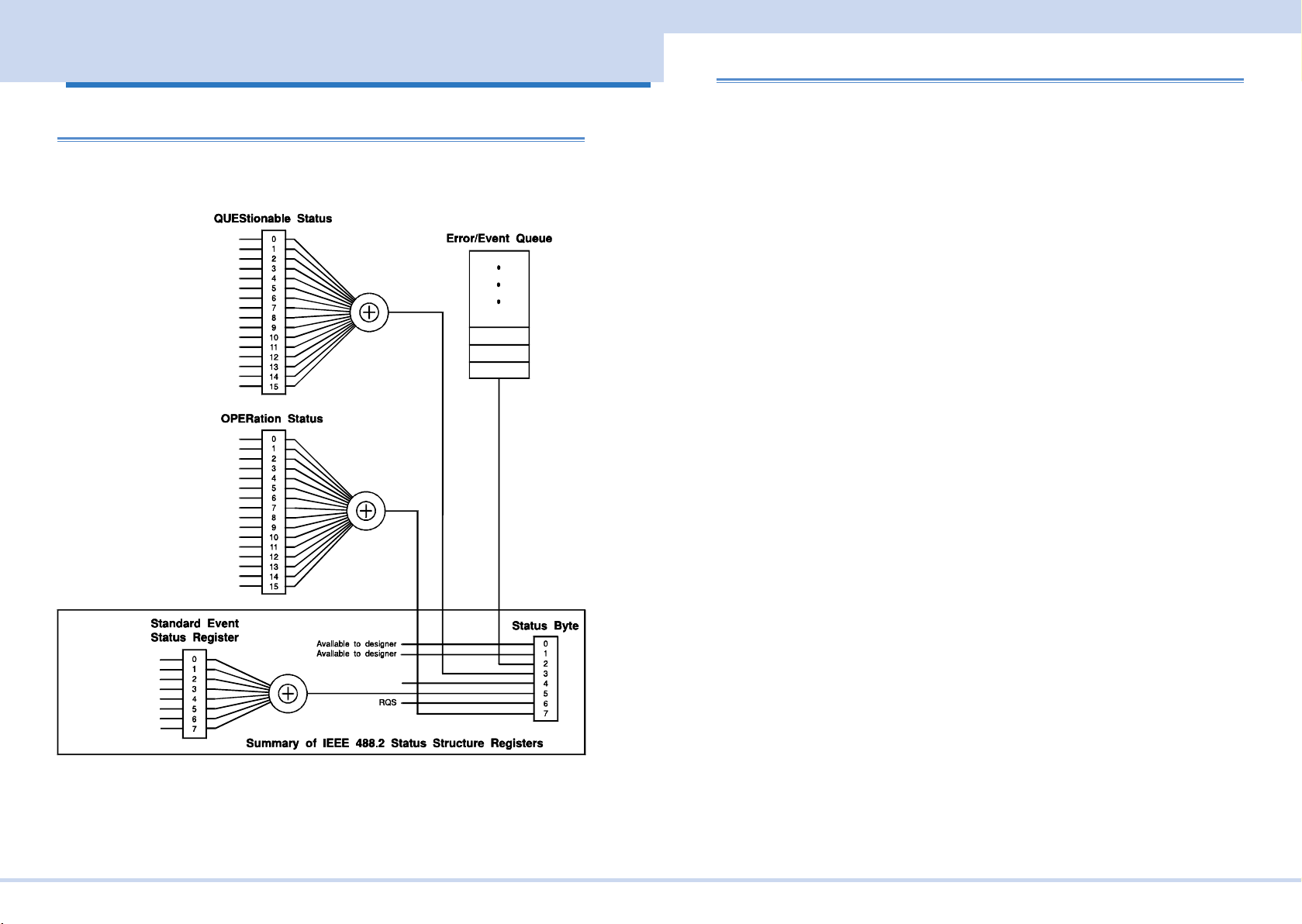
Register Structure
The character "+" represents the logical sum of the register bits.
OV
OC
HWF
LV
OT
NOT USED
NOT USED
NOT USED
CAL
OP
CL-PEAK
PL
CL-RMS
SF
MEAS-OVLD
NOT USED
NOT USED
NOT USED
NOT USED
NOT USED
MEAS_activ
WTG_meas
STG_tran
NOT USED
CV
NOT USED
NOT USED
NOT USED
NOT USED
NOT USED
NOT USED
NOT USED
Architecture
IEEE488.2 and SCPI registers are used for the status reports.
In each SCPI status register, there are the following sub registers: CONDition register, EVENt register, ENABle register, PTRansition lter, and NTRansition lter.
CONDition register
The transition of the CONDition register is automatic and reects the condition of the
PCR-MA in real-time. Reading this register does not affect the contents.
EVENt register
The EVENt register bits are automatically set according to the changes in the CONDition register. The rule varies depending on the positive and negative transition lters
(PTRansition and NTRansition). The EVENt register is reset when it is read.
ENABle register
The ENABle register enables the reports to the summary bit or status bit of the event
bit.
Transition lter
The PTRansition (positive transition) lter is used to report events when the condition
changes from false to true.
The NTRansition (negative transition) lter is used to report events when the condi-
tion changes from true to false.
If both the positive lter and the negative lter are set to true, events can be reported
each time the status changes.
If both lters are cleared, event reporting is disabled.
Operation Complete
Request Control
Device Dependent Error
Query Error
Execution Error
Command Error
Reserved
Power On
RQS/MSS
KIKUSUI Electronics Corp. PCR-MA Interface Manual
Page 44
STATus Command
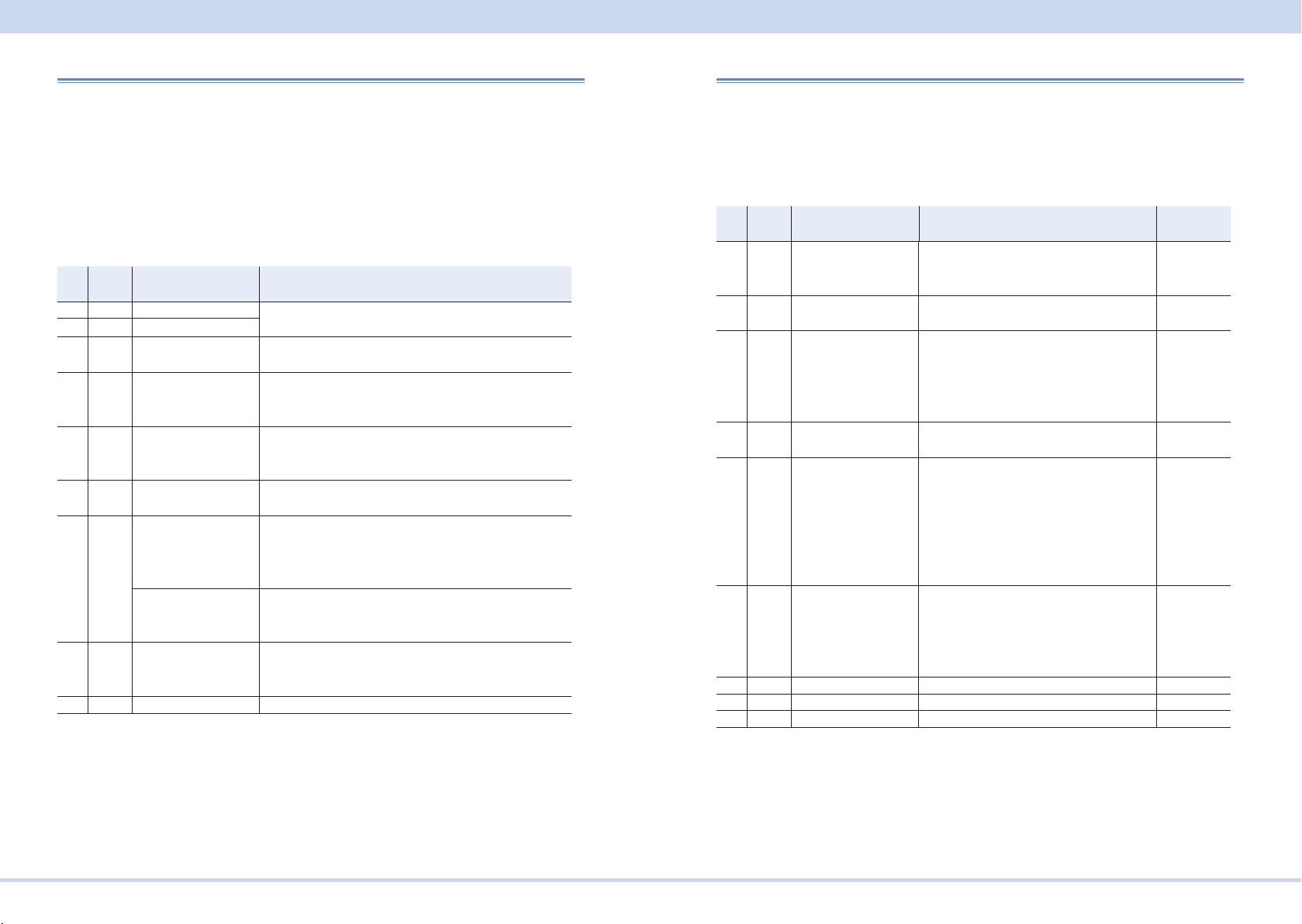
Status byte register
The status byte register stores STB and RQS (MSS) messages as dened by the
IEEE488.1 standard. The status byte register can be read using IEEE488.1 serial
polling or the IEEE488.2 common command *STB?.
When serial polling is carried out, bit 6 responds with the request service (RQS). The
status byte value is not changed by serial polling.
*STB? makes the device transmit the contents of the status byte register and the
master status summary (MSS) message.
*STB? does not change the status byte, MSS, or RQS.
Bit Bit
0 1 Reserved Reserved for future use by the IEEE488. The bit value
1 2 Reserved
2 4 Error/Event Queue If data exists in the error or event queue, this bit is set to
3 8 Questionable Status
4 16 Message Available
5 32 Standard Event Status
6 64 Request Service
7 128 Operation Status Reg-
8-15 Not Used --
Bit name Description
weight
Register (QUES)
(MAV)
Bit Summary (ESB)
(RQS)
Master Status Sum-
mary (MSS)
ister (OPER)
is notied as zero.
true.
This bit is set to true when a bit is set in the QUEStion-
able event status register and the corresponding bit in
the QUEStionable status enable register is true.
This bit is set to true when a request is received from
the digital programming interface and the PCR-MA is
ready to output the data byte.
This bit is set to true when a bit is set in the event status
register.
This bit is set to true when a bit is set in the service
request enable register, and the corresponding bit exists
in the status byte.
The SRQ line of the GPIB is set.
This bit is set to true when a bit in the status byte reg-
ister is set to 1 and the corresponding bit in the service
request enable register is set to 1.
This bit is set to true when a bit is set in the OPERation
event status register and the corresponding bit in the
OPERation status enable register is set.
Event status register
The event status register bits are set when certain events occur during PCR-MA operation. All bits of the event status register are set by the error event queue.
The register is dened by the IEEE488.2 standard and is controlled by the IEEE488.2
common commands *ESE, *ESE?, and *ESR?.
See SYST:ERR? for the descriptions of the errors.
Bit Bit
0 1 Operation Com-
1 2 Request Control
2 4 Query Error(QYE) Set when an attempt is made to read data
3 8 Device Dependent
4 16 Execution Error(EXE) Set when the PCR-MA evaluates that
5 32 Command Error(C-
6 64 User Request(URQ) Not used -7 128 Power On(PON) Set when the power is turned on. -8-15 Reserved Not used --
Bit name Description Error code
weight
Set when an *OPC command is received
plete(OPC)
(RQC)
Error(DDE)
ME)
and all operations in standby are com-
plete.
Not used --
from the output queue when there is no
output or the error queue is in wait status.
Indicates that there is no data in the error
queue.
Set when there is a device-specic error. -300 to -399
the program data following the header is
outside the formal input range or does not
match the performance of the PCR-MA.
This indicates that a valid SCPI command
may not be executed correctly depending
on the conditions of the PCR-MA.
ISet when an IEEE 488.2 syntax error is
detected, when an unidentiable header is
received, or when a group execution trig-
ger enters the internal IEEE 488.2 SCPI
command input buffer.
-800 to -899
-400 to -499
100 to 999
-200 to -299
-100 to -199
KIKUSUI Electronics Corp. PCR-MA Interface Manual
Page 45
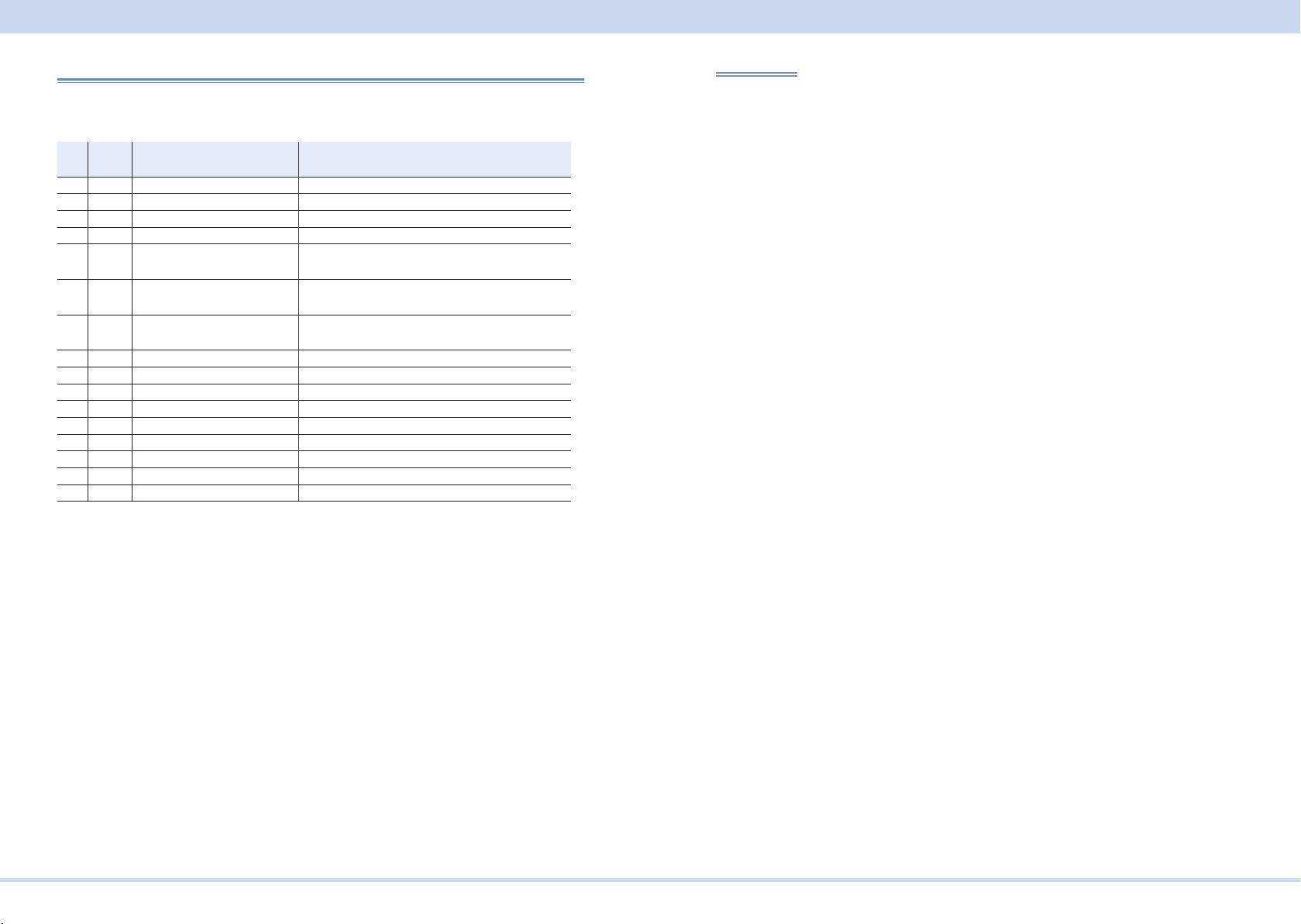
STATus Command
OPERation status register
The OPERation status register is a 16-bit register that contains conditions that are
part of the PCR-MA normal operations.
Bit Bit
0 1 NOT USED -1 2 NOT USED --
2 4 NOT USED -3 8 NOT USED -4 16 MEAS_activ Indicates whether measurement is in progress
5 32 WTG_meas Indicates whether the PCR-MA is waiting for a
6 64 WTG_tran Indicates whether the PCR-MA is waiting for a
7 128 NOT USED -8 256 CV CV output
9 512 NOT USED -10 1024 NOT USED -11 2048 NOT USED -12 4096 NOT USED -13 8192 NOT USED -14 16384 NOT USED --
15 32768 NOT USED Always zero
Bit name Description
weight
on the PCR.-MA
measurement trigger (*TRG/TRIG:ACQ).
setting change trigger (*TRG/TRIG:TRAN).
STAT:OPER
Queries the event of the OPERation status register.
A query clears the contents of the register.
Command
STATus:OPERation[:EVENt]?
Response: NR1
KIKUSUI Electronics Corp. PCR-MA Interface Manual
Page 46

STATus Command
STAT:OPER:COND
Queries the condition of the OPERation status register.
A query does not clear the contents of the register.
Command
STATus:OPERation:CONDition?
Response: NR1
STAT:OPER:ENAB
Sets the enable register of the OPERation status register.
Command
STATus:OPERation:ENABle <NRf>
STATus:OPERation:ENABle?
Parameter
Value: 0 to 65535 (0 by default)
Response: NR1
KIKUSUI Electronics Corp. PCR-MA Interface Manual
Page 47

STATus Command
STAT:OPER:NTR
Sets the negative transition of the OPERation status register.
Command
STATus:OPERation:NTRansition <NRf>
STATus:OPERation:NTRansition?
Parameter
Value: 0 to 65535 (0 by default)
Response: NR1
STAT:OPER:PTR
Sets the positive transition of the OPERation status register.
Command
STATus:OPERation:PTRansition <NRf>
STATus:OPERation:PTRansition?
Parameter
Value: 0 to 65535 (0 by default)
Response: NR1
KIKUSUI Electronics Corp. PCR-MA Interface Manual
Page 48
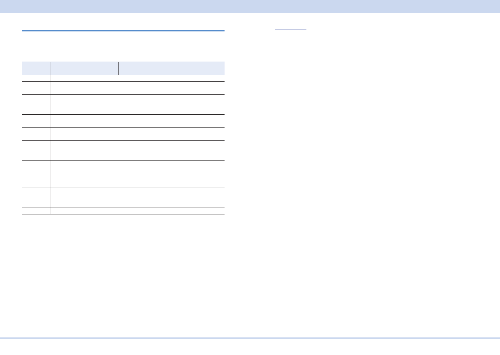
STATus Command
QUEStionable status register
The QUEStionable status register is a 16-bit register that stores information related to
the questionable events and status during PCR-MA operation.These register bits may
indicate problems with the measured data of the PCR-MA.
Bit Bit
0 1 OV (Over Voltage Protection) Over voltage protection has been activated
1 2 OC (Over Current Protection) Over current protection has been activated
2 4 HWF (Hardware Failure) Device error has occurred.
3 8 LV (Low Voltage Protection) Low voltage protection has been activated
4 16 OT (Over Temperature Protec-
5 32 Not Used -6 64 Not Used -7 128 Not Used -8 256 CAL(CALibration) Calibration data is invalid
9 512 OP (Over Power protection) Overpower protection has been activated
10 1024 CL-PEAK (Current Limit on
11 2048 PL(Power Limit) Overpower overload has been activated
12 4096 CL-RMS(Current Limit on
13 8192 SF(Remote sensing failer) Sensing error has occurred.
14 16384 MEAS-OVLD(Measurement
15 32768 Not Used Always zero
Bit name Description
weight
Over temperature protection has been activated
tion)
Current limit control has been activated
PEAK)
Overcurrent (peak) overload has been activated
RMS)
Overload has been detected.
overload detected)
STAT:QUES
Queries the event of the QUEStionable status register.
A query clears the contents of the register.
Command
STATus:QUEStionable[:EVENt]?
Response: NR1
KIKUSUI Electronics Corp. PCR-MA Interface Manual
Page 49

STATus Command
STAT:QUES:COND
Queries the condition of the QUEStionable status register.
A query does not clear the contents of the register.
Command
STATus:QUEStionable:CONDition?
Response: NR1
STAT:QUES:ENAB
Sets the enable register of the QUEStionable status register.
Command
STATus:QUEStionable:ENABle <NRf>
STATus:QUEStionable:ENABle?
Parameter
Value:0 to 65535 (0 by default)
Response: NR1
KIKUSUI Electronics Corp. PCR-MA Interface Manual
Page 50

STATus Command
STAT:QUES:NTR
Sets the negative transition of the QUEStionable status register.
Command
STATus:QUEStionable:NTRansition <NRf>
STATus:QUEStionable:NTRansition?
Parameter
Value:0 to 65535 (0 by default)
Response: NR1
STAT:QUES:PTR
Sets the positive transition of the QUEStionable status register.
Command
STATus:QUEStionable:PTRansition <NRf>
STATus:QUEStionable:PTRansition?
Parameter
Value:0 to 65535 (0 by default)
Response: NR1
KIKUSUI Electronics Corp. PCR-MA Interface Manual
Page 51

SYSTem Command
Preset status
STAT:PRES
Resets the ENABle, PTRansition, and NTRansition lter registers of all status regis-
ters (including sub registers) to their default values
Default values:
STATus:ENABle = 0x0000
STATus:PTRansition = 0x7FFF
STATus:NTRansition = 0x0000
Command
STATus:PRESet
SYSTem Command
SYST:COMM:GPIB:ADDR
Sets the GPIB address.
Command
SYSTem:COMMunicate:GPIB:ADDRess <NR1>
SYSTem:COMMunicate:GPIB:ADDRess?
Parameter
Value: 1 to 30
(Example)
SYST:COMM:GPIB:ADDR 23
Response: NR1
KIKUSUI Electronics Corp. PCR-MA Interface Manual
Page 52

SYSTem Command
SYST:COMM:LAN:CONT
Queries the TCP port number used by SCPI-RAW.
SYST:COMM:LAN:CONT and SYST:COMM:TCP:CONT are aliases.
Command
SYSTem:COMMunicate:LAN:CONTrol?
Response
Returns +5025.
SYST:COMM:RLST
Sets the operation of the PCR-MA to local or remote.
Command
SYSTem:COMMunicate:RLSTate <character>
SYSTem:COMMunicate:RLSTate?
Parameter
Value: LOCal Sets the PCR-MA to local mode (Remote Disable; the RMT
LED turns off).
Disable state enables both panel operations and commands.
This is a substitute command for IEEE488.1 ren FALSE (Re-
mote Disable).
REMote Sets the PCR-MA operation to remote mode.
All panel keys except the LOCAL key are locked.
This is a substitute command for the IEEE488.1 REN (Remote
Enable) command and address designation.
RWLock Sets the PCR-MA operation to remote mode.
All panel keys are locked (the LOCAL key is also locked). This
is a substitute command for the IEEE488.1 llo (Local Lock
Out) command.
(Example)
SYST:COMM:RLST REM
Response: character
KIKUSUI Electronics Corp. PCR-MA Interface Manual
Page 53

SYSTem Command
SYST:COMM:TCP:CONT
Queries the TCP port number used by SCPI-RAW.
SYST:COMM:LAN:CONT and SYST:COMM:TCP:CONT are aliases.
Command
SYSTem:COMMunicate:TCPip:CONTrol?
Response
Returns +5025.
SYST:COMM:USB:ADDR
Queries the address information of the USB interface.
Command
SYSTem:COMMunicate:USB:ADDRess?
Response
Returns the address information in the following order in a comma-separated for-
mat.
VID (vendor ID) <NR1>, vendor name <character>, PID (product ID)<NR1>, product name <character>, serial number <character>
Response example: For a PCR500MA with a serial number AB123456
2878,KIKUSUI,4176,PCR500MA,AB123456
is returned.
KIKUSUI Electronics Corp. PCR-MA Interface Manual
Page 54

SYSTem Command
SYST:CONF:TRAC
Sets whether to display communication errors by performing a debug trace.
If the debug trace function is turned on, error codes (example: Err-100) are shown on
the PCR-MA display.
Command
SYSTem:CONFigure:TRACe <boolean>
SYSTem:CONFigure:TRACe?
Parameter
Value: ON(1) Display communication errors
OFF(0) Not display communication errors (default)
(Example)
SYST:CONF:TRAC ON
Response: NR1
SYST:ERR
Reads the oldest error information or event information from the error queue.
The error queue can store up to 255 errors. -> Tutorial “Error Checking”
Use the *CLS command to clear the error queue.
Command
SYSTem:ERRor[:NEXT]?
Response
Returns the oldest error or event information in the error/event queue as follows:
(Example) When there are no errors or events
+0"No error"
(Example) When a command that cannot be executed under the current operating
conditions has been received
-221,"Settings conict"
KIKUSUI Electronics Corp. PCR-MA Interface Manual
Page 55

SYSTem Command
SYST:ERR:COUN
Queries the number of unread errors in the error queue.
Command
SYSTem:ERRor:COUNt?
Response
NR1
Returns +0 if there are no errors.
SYST:KLOC
Sets and releases the panel operation lock (keylock).
Command
SYSTem:KLOCk <boolean>
SYSTem:KLOCk?
Parameter
Value: ON(1) Key lock is set.
OFF(0) Key lock is released.
(Example)
SYSTem:KLOC ON
Response: NR1
KIKUSUI Electronics Corp. PCR-MA Interface Manual
Page 56

SYSTem Command
SYST:LOC/ SYST:REM/ SYST:RWL
This is an old style command.
When creating new programs, use SYST:COMM:RLST.
Command
SYSTem:LOCal
SYSTem:REMote
SYSTem:RWLock
SYST:OPT
Queries the option that are installed in the PCR-MA.
This is an alias for *OPT.
Command
SYSTem:OPTion?
Response
Returns the optional interface board that is installed in the PCR-MA in comma-separated string format. Returns 0 if there is no option installed.
“IB22” IB22 GPIB interface board
“EX08” EX08-PCR-MA External signal interface board
KIKUSUI Electronics Corp. PCR-MA Interface Manual
Page 57

TRIGger Command
SYST:VERS
Queries the version of the SCPI specications to which the PCR-MA conforms.
Command
SYSTem:VERSion?
Response
Returns 1999.0.
TRIGger Command
TRIG:ACQ
Executes a software trigger for a ACQuire trigger subsystem.
Command
TRIGger:ACQuire[:IMMediate]
KIKUSUI Electronics Corp. PCR-MA Interface Manual
Page 58

TRIGger Command
TRIG:ACQ:SOUR
Sets the condition (trigger source) that determines when the ACQuire trigger subsystem actually starting the measuremen after the PCR-MA receives the INIT:ACQ
command.
Command
TRIGger:ACQuire:SOURce <character>
TRIGger:ACQuire:SOURce?
Parameter
Value: IMMediate Start the measurement immediately (default)
BUS Wait for a software trigger (*TRG, TRIG:ACQ, or IEEE488.1
get (Group Execute Trigger)) to start the measurement
Settings are reset to default when the *RST command is sent.
(Example)
TRIG:ACQ:SOUR BUS
Response: character
TRIG:TRAN
Executes a software trigger for the TRANsient trigger subsystem.
Command
TRIGger:TRANsient[:IMMediate]
KIKUSUI Electronics Corp. PCR-MA Interface Manual
Page 59

TRIGger Command
TRIG:TRAN:SOUR
Sets the condition (trigger source) that determines when the TRANsient trigger
subsystem actually changing the setting after the PCR-MA receives the INIT:TRAN
command.
Command
TRIGger:TRANsient:SOURce <character>
TRIGger:TRANsient:SOURce?
Parameter
Value: IMMediate The setting is changed immediately (default).
BUS The setting is changed when a software trigger is received
(use the *TRG, TRIG:TRAN, or IEEE488.1 get (Group Execute Trigger) command to change the setting; default).
Settings are reset to default when the *RST command is sent.
(Example)
TRIG:TRAN:SOUR BUS
Response: character
TRIG:SYNC:PHAS
Sets the phase angle of the OUTPUT on.
This is valid when the output-on phase control is on (TRIG:SYNC:SOUR PHAS).
Command
TRIGger:SYNChronize:PHASe[:ON] <numeric>
TRIGger:SYNChronize:PHASe[:ON]?
Parameter
Value: 0 to 359 phase angle of the output on (0 by default)
Unit: DEG
Settings are reset to default when the *RST command is sent.
(Example)
TRIG:SYNC:PHAS 270
Response: NR3
KIKUSUI Electronics Corp. PCR-MA Interface Manual
Page 60
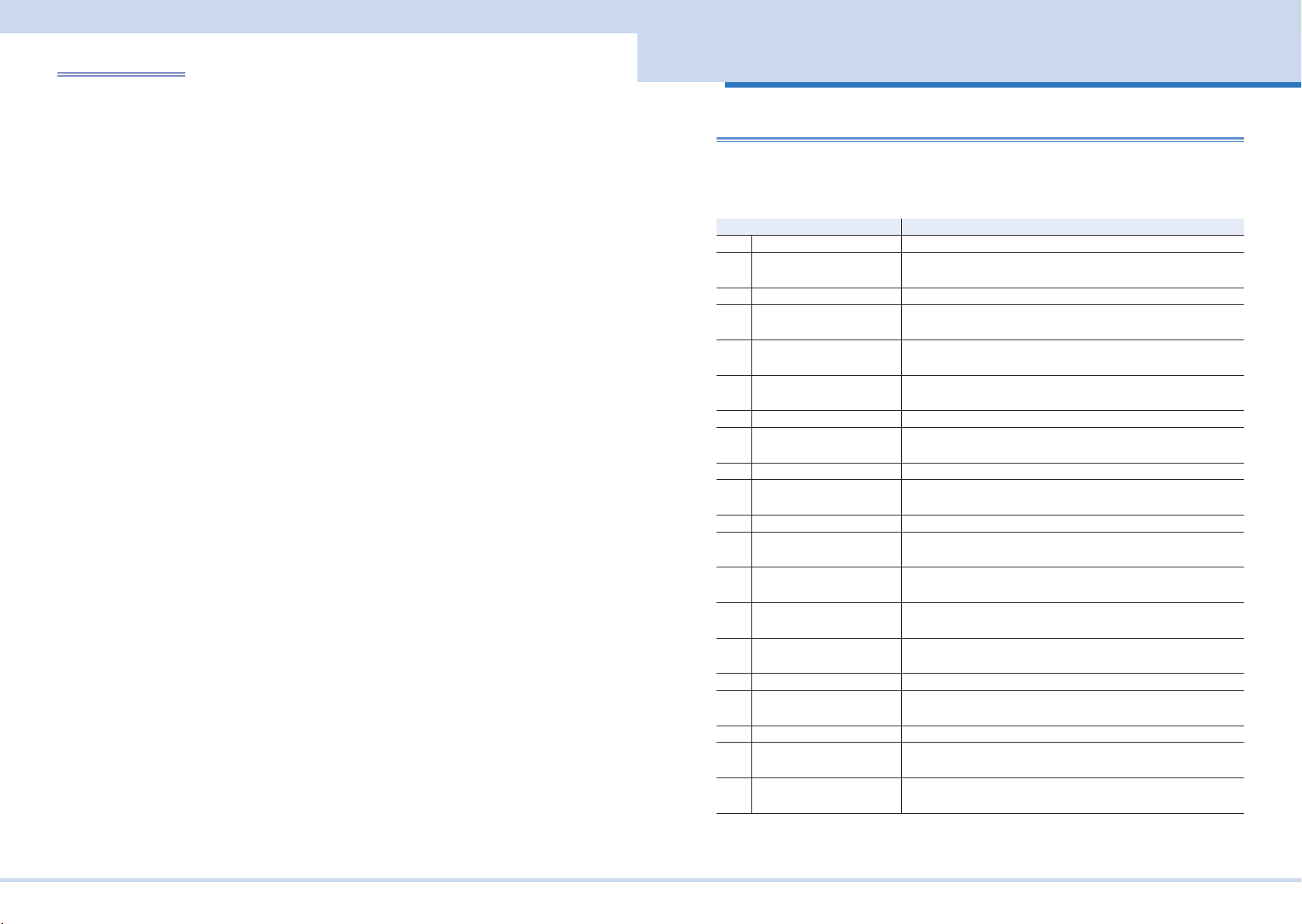
A List of Errors
TRIG:SYNC:SOUR
Sets the OUTPUT on phase control when OUTP ON is sent.
Use TRIG:SYNC:PHAS to set the output-on phase angle.
Command
TRIGger:SYNChronize:SOURce <character>
TRIGger:SYNChronize:SOURce?
Parameter
Value: IMMediate Disables OUTPUT on phase control (default)
PHAse Enables OUTPUT on phase control
Settings are reset to default when the *RST command is sent.
(Example)
TRIG:SYNC:SOUR PHAS
Response: character
A List of Errors
Command errors
An error in the range [ -199, -100 ] indicates that an IEEE 488.2 syntax error has
been detected by the instrument’s parser. The occurrence of any error in this class
shall cause the Command Error (bit 5) in the event status register to be set.
Error code Error message description
-100 Command error This is the generic syntax error.
-101 Invalid character A syntactic element contains a character that is invalid for that
type.
-102 Syntax error An unrecognized command or data type was encountered.
-103 Invalid separator The parser was expecting a separator and encountered an
illegal character.
-104 Data type error The parser recognized a data element different than one
allowed.
-105 GET not allowed A Group Execute Trigger was received within a program mes-
sage.
-108 Parameter not allowed More parameters were received than expected for the header.
-109 Missing parameter Fewer parameters were recieved than required for the head-
er.
-110 Command header error An error was detected in the header.
-112 Program mnemonic too
long
-113 Undened header The header is undened for this device.
-114 Header sufx out of range The value of a numeric sufx attached to a program mnemon-
-115 Unexpected number of
parameters
-120 Numeric data error This error is generated when parsing a data element that ap-
-128 Numeric data not allowed A legal numeric data element was received, but the device
-130 Sufx error This error is generated when parsing a sufx.
-131 Invalid sufx The sufx does not follow the syntax or the sufx is inappro-
-134 Sufx too long The sufx contained more than 12 characters.
-138 Sufx not allowed A sufx was encountered after a numeric element which does
-140 Character data error This error is generated when parsing a character data ele-
The header contains more that twelve characters.
ic.
The number of parameters received does not correspond to
the number of parameters expected.
pears to be numeric, including the nondecimal numeric types.
does not accept one in this position for the header.
priate for this device.
not allow sufxes.
ment.
KIKUSUI Electronics Corp. PCR-MA Interface Manual
Page 61
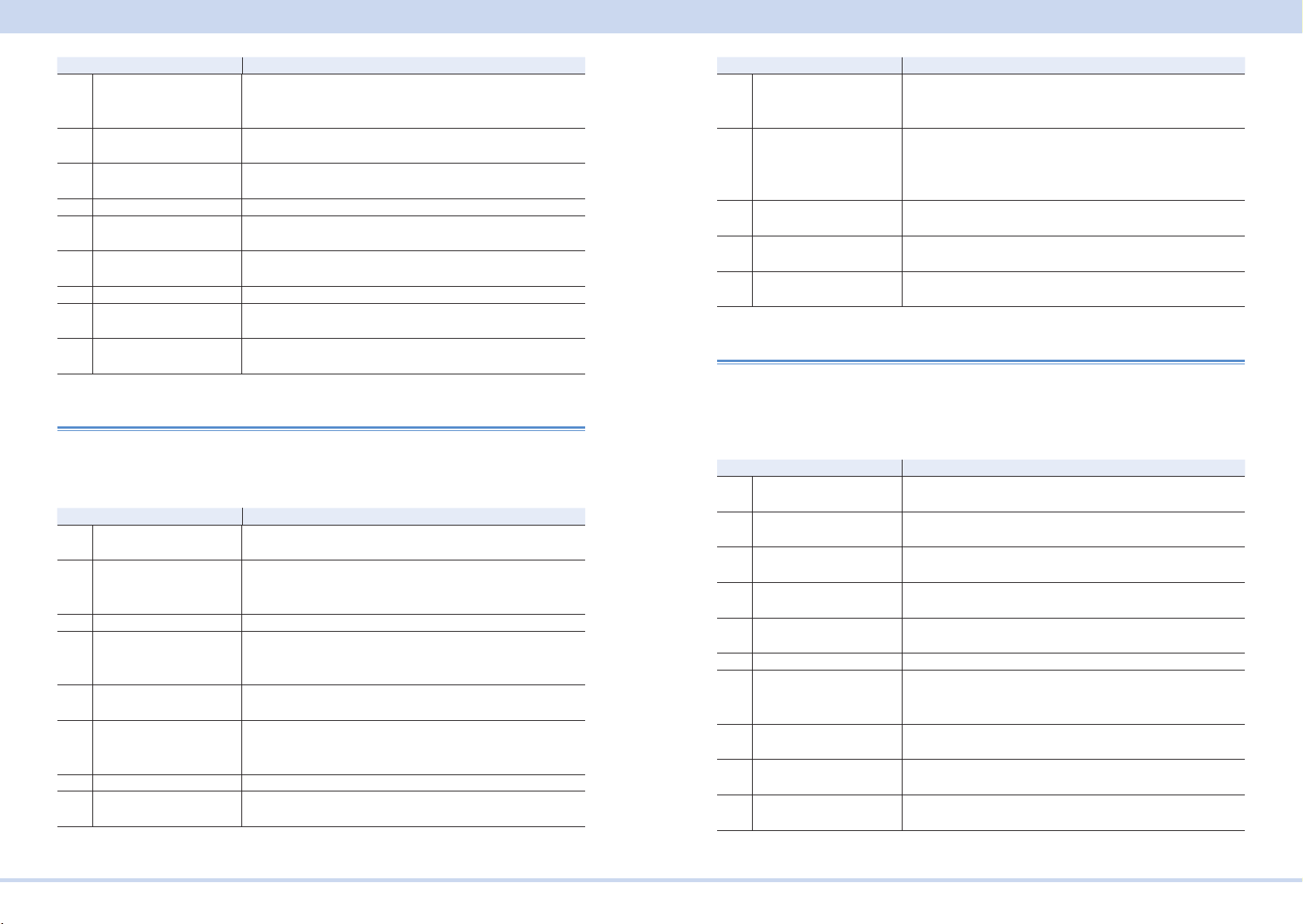
A List of Errors
Error code Error message description
-141 Invalid character data Either the character data element contains an invalid char-
acter or the particular element received is not valid for the
header.
-144 Character data too Long The character data element contains more than twelve char-
acters.
-148 Character data not al-
lowed
-150 String data error This error is generated when parsing a string data element.
-151 Invalid string data A string data element was expected, but was invalid for some
-158 String data not allowed A string data element was encountered but was not allowed
-160 Block data error This error is generated when parsing a block data element.
-170 Expression error This error is generated when parsing an expression data
-180 Macro error This error is generated when dening a macro or executing a
A legal character data element was encountered where pro-
hibited by the device.
reason.
by the device at this point in parsing.
element.
macro.
Execution errors
An error in the range [-299, -200] indicates that an error has been detected by the
instrument’s execution control block. The occurrence of any error in this class shall
cause the Execution Error (bit 4) in the event status register to be set.
Error code Error message description
-200 Execution error (generic) This is the generic syntax error for devices that cannot detect
more specic errors.
-203 Command protected Indicates that a legal password-protected program command
or query could not be executed because the command was
disabled.
-210 Trigger error Trigger error.
-211 Trigger ignored Indicates that a GET, *TRG, or triggering signal was received
and recognized by the device but was ignored because of
device timing considerations.
-213 Init ignored Indicates that a request for a measurement initiation was
ignored as another measurement was already in progress.
-214 Trigger deadlock Indicates that the trigger source for the initiation of a mea-
surement is set to GET and a subsequent measurement
query was received.
-220 Parameter error Indicates that a program data element related error occurred.
-221 Settings conict Indicates that a legal program data element was parsed but
could not be executed due to the current device state.
Error code Error message description
-222 Data out of range Indicates that a legal program data element was parsed but
could not be executed because the interpreted value was out-
side the legal range as dened by the device.
-223 Too much data Indicates that a legal program data element of block, ex-
pression, or string type was received that contained more
data than the device could handle due to memory or related
device-specic requirements.
-224 Illegal parameter value Used where an exact value, from a list of possible values,
was expected.
-230 Data corrupt or stale Possibly invalid data; new reading started but not completed
since last access.
-241 Hardware missing Indicates that a legal program command or query could not
be executed because of missing device hardware.
Device-specic errors
An error in the range [-399, -300] indicates that the instrument has detected an error
which is not a command error, a query error, or an execution error. The occurrence
of any error in this class should cause the device-specic error bit (bit 3) in the event
status register to be set.
Error code Error message description
-310 System error Indicates that some error, termed “system error” by the de-
vice, has occurred.
-311 Memory error Indicates some physical fault in the device’s memory, such as
parity error.
-313 Calibration memory lost Indicates that nonvolatile calibration data used by the *CAL?
command has been lost.
-314 Save/recall memory lost Indicates that the nonvolatile data saved by the *SAV? com-
mand has been lost.
-315 Conguration memory lost Indicates that nonvolatile conguration data saved by the
device has been lost.
-330 Self-test failed Self-test failed
-350 Queue overow A specic code entered into the queue in lieu of the code that
caused the error. This code indicates that there is no room in
the queue and an error occurred but was not recorded.
-360 Communication error Communication error when the ow control is turned off. This
error applies when the RS232C interface is used.
-362 Framing error in program
message
-363 Input buffer overrun Buffer overrun error. This error applies when the RS232C
Framing error. This error applies when the RS232C interface
is used.
interface is used.
KIKUSUI Electronics Corp. PCR-MA Interface Manual
Page 62
A List of Errors
Error code Error message description
-365 Time out error Time out error. This error applies when the RS232C interface
is used.
Query errors
An error in the range [-499, -400] indicates that the output queue control of the instrument has
detected a problem with the message exchange protocol described in IEEE 488.2, chapter 6.
The occurrence of any error in this class shall cause the Query Error (bit 2) in the event status
register to be set.
Error code Error message description
-400 Query error (generic) This is the generic query error for devices that cannot detect
more specic errors.
-410 Query INTERRUPTED Received a new command before the response was read.
-420 Query UNTERMINATED The controller attempted to read the response after the device
received an unsupported query or has not received a query.
The -100 "COMMAND ERROR" error and this error are
stored in the error queue. The controller will time out.
-430 Query DEADLOCKED The error queue, input buffer, and output buffer are full when
sending large binary data as a response, and the transmis-
sion timing is off.
-440 Query UNTERMINATED
after indenite response
Received a separate query in semicolon-delimited format
after a query that returns a response in an indenite form.
(Example: A command such as the following. *IDN?;SYS-
T:ERR?)
Operation Complete Event
An error in the range [-899: -800] is used when the instrument wishes to report a
488.2 operation complete event to the error/event queue. This event occurs when
instrument’s synchronization protocol, having been enabled by an *OPC command,
completes all selected pending operations. This protocol is described in IEEE 488.2,
section 12.5.2. This event also sets the operation complete bit (bit 0) of the Standard
Event Status Register.
Device-dependent errors
The occurrence of any error in this class shall cause the Device Dependent Error (bit 3)
in the event status register to be set.
Errors that have a number of +900 or greater are generated as a result of the self test
that is run when the *TST? query is received.
Error code
+131 Operation conicts with OUTPUT ON state
+132 Operation conicts with PROTECTION state
+133 Operation conicts with OUTPUT COUPLE setting
+134 Operation conicts with AUTO RANGE
+135 Operation conicts with EXT-AC or EXT-DC program source
+140 LOW RANGE conicts with existing VOLT[:IMM] setting
+141 LOW RANGE conicts with existing VOLT:TRIG setting
+142 LOW RANGE conicts with existing VOLT:OFFS[:IMM] setting
+143 LOW RANGE conicts with existing VOLT:OFFS:TRIG setting
+150 Overlaid peak value of AC (IMM) and DC (IMM) components is too large
+151 Overlaid peak value of AC (IMM) and DC (TRIG) components is too large
+152 Overlaid peak value of AC (TRIG) and DC (IMM) components is too large
+153 Overlaid peak value of AC (TRIG) and DC (TRIG) components is too large
+160 IMM setting is out of range
+161 TRIG setting is out of range
+162 Overlaid peak value with existing AC (IMM) component is too large
+163 Overlaid peak value with existing AC (TRIG) component is too large
+164 Overlaid peak value with existing DC (IMM) component is too large
+165 Overlaid peak value with existing DC (TRIG) component is too large
+166 LIM:LOW setting is out of range
+167 LIM:UPP setting is out of range
+168 IMM setting value and soft-limits conict with LOWER<=VALUE<=UPPER condition
+169 TRIG setting value and soft-limits conict with LOWER<=VALUE<=UPPER condition
+302 Option not installed
+309 Cannot initiate, voltage and frequency in xed mode
+901 HW failure (DSP DETECT state)
+902 HW failure (DSP VCC state)
+903 HW failure (DSP INPUT state)
+904 HW failure (DSP Communication Failure)
Error code Error message description
-800 Operation complete The instrument has completed all selected pending opera-
tions in accordance with the IEEE 488.2, 12.5.2 synchroniza-
tion protocol.
KIKUSUI Electronics Corp. PCR-MA Interface Manual
Page 63
Tutorial
Processing Time of Commands
The command processing time is the time until the next command is accepted.
The processing times indicated here are typical values. They are not guaranteed.
The processing times vary depending on the settings and the measurement conditions.
It does not include the response time of the hardware.
Command Processing time (ms) Description
VOLT 1.997 1.809 1.809 1.123 0.05 Sets the voltage
MEAS:VOLT:AC? 665.531 665.640 665.578 665.516 665.571 Queries the
FREQ 1.997 1.825 1.825 1.170 0.05 Sets the frequen-
MEAS:CURR:AC? 665.435 665.435 665.734 666.249 665.431 Queries the
*RST 163.645 163.645 163.988 88.827 0.06 Performs a device
*1
: Using USB-GPIB by National Instruments
*2
: 100BASE-TX Ethernet
GPIB
*1
USB LAN
*2
VXI-11 HiSlip SCPI-RAW
measured voltage
output
cy
measured current
output
reset.
Tutorial
Programming AC Output
■ Setting the AC voltage and frequency
The AC output voltage and frequency are controlled with the VOLTage and FREQuency commands. Prior to programming the output, it is recommended that the
appropriate output mode and voltage range be selected.
OUTPut:COUPling AC ‘Sets the output mode to AC mode
VOLTage:RANGe 155 ‘Sets the voltage range to the 155V range
VOLTage 110 'Set the AC voltage to 110 V
FREQuency 55 'Sets the frequency to 55 Hz
OUTPut ON 'Turn the output on
■ Setting the AC voltage limit and frequency limit
The maximum allowable value for VOLTage varies depending on the VOLTage:RANGe setting.
The minimum and maximum allowable values for VOLTage and FREQuency commands may vary depending on the VOLTage:LIMit and FREQuency:LIMit settings.
The VOLTage and FREQuency settings must be specied within the upper and lower
limits.
The voltage limit and frequency limit settings are safety interlock functions that pre-
vent unexpected miss-operation or miss-programming. They are not output limiting
functions.
VOLTage:RANGe 155 ‘Sets the voltage range to the 155V range
VOLTage:LIMit:UPPer MAX ‘Sets the voltage upper limit to maximum
VOLTage:LIMit:LOWer MIN ‘Sets the voltage lower limit to minimum
VOLTage 110 ‘Sets the AC voltage to 110 V
FREQuency:LIMit:UPPer MAX ‘Sets the frequency upper limit to 500 Hz
FREQuency:LIMit:LOWer MIN ‘Sets the frequency lower limit to 40 Hz
FREQuency 55 ‘Sets the frequency to 55 Hz
Above example expands the upper/lower limits to the widest span allowing the VOLTage and FREQuency to be set to any value within the given range.
When the VOLTage:RANGe is set to 155 V, VOLTage setting cannot exceed 157.5 V.
■ Query
To query the maximum and minimum allowed values for the VOLTage and FREQuency commands, use the query with the MINimum and/or MAXimum parameters.
VOLTage? MINimum
KIKUSUI Electronics Corp. PCR-MA Interface Manual
Page 64

Tutorial
VOLTage? MAXimum
FREQuency? MINimum
FREQuency? MAXimum
Programming DC Output
■ Setting the DC voltage
The DC output voltage is controlled with the VOLTage:OFFSet command. Prior to
programming the output, it is recommended that the appropriate output mode and
voltage range be selected.
OUTPut:COUPling DC ‘Sets the output mode to DC mode
VOLTage:RANGe 155 ‘Sets the voltage range to the 155V range
VOLTage:OFFSet 40 ‘Sets the DC voltage to 40 V
OUTPut ON ‘Turns the output on
Once the power supply output is enabled (turned on), voltage range settings cannot
be changed. On the other hand, the VOLTage:OFFSet setting can always be changed
while the output is on.
■ Setting the DC voltage limit
The maximum allowable value for VOLTage:OFFSet also varies depending on the
VOLTage:RANGe setting. The minimum and maximum allowable values for VOLTage:OFFSet command may vary depending on the VOLTage:OFFSet:LIMit settings.
VOLTage:RANGe 155 ‘Sets the voltage range to the 155V range
VOLTage:OFFSet:LIMit:UPPer MAX ‘Sets the voltage upper limit to maximum
VOLTage:OFFSet:LIMit:LOWer MIN ‘Sets the voltage lower limit to minimum
VOLTage:OFFSet 40 ‘Sets the DC voltage to 40 V
Above example expands the upper/lower limits to the widest span allowing the VOLTage:OFFSet to be set to any value within the given range.
When the VOLTage:RANGe is set to 155 V, VOLTage:OFFSet setting cannot exceed
+/-222.5.0 V. The VOLTage:RANGe species the voltage range using the AC voltage
expression. The allowable DC voltage range for the 155 V range is +/-222.5 V, and
that for the 310 V range is +/-445.0 V.
By *RST default, the :VOLTage:OFFSet:LIMit:LOWer setting is not set to its MINimum. It is set to 0 for operational safety.
■ Query
To query the maximum and minimum allowed values for the VOLTage:OFFSet command, use the query with the MINimum and/or MAXimum parameters.
VOLTage:OFFSet? MINimum
VOLTage:OFFSet? MAXimum
KIKUSUI Electronics Corp. PCR-MA Interface Manual
Page 65

Tutorial
State of Trigger subsystem
PCR-MA has three different trigger subsystems -TRANsient, ACQuire, and SYNChronize.
The TRANsient and ACQuire trigger subsystems have three states (IDLE state, INITiated state, WTG state).
The SYNChronize subsystem is always in the INITiated state.
■ IDLE state
When the PCR-MA is turned on, all the trigger subsystems are in the IDLE state. In
this state, the trigger subsystems ignore all triggers. Sending one of the following
commands at any time also returns the trigger subsystems to the IDLE state.
The sequence does not start in the IDLE state, even when TRG is sent.
ABORt (“:INIT:CONT:ACQ OFF;:ABOR” if the auto continue mode is turned on)
*RST
*RCL
IEEE488.1 sdc(Selected Device Clear) or dcl(Device Clear)
■ INITiated state
If INIT is sent in the IDLE state, the trigger function starts and the PCR-MA enters the
INITiated state.
If the trigger source is set to IMMediate, the settings are changed immediately, or the
measurement, power line abnormality simulation, or sequence starts immediately.
If the trigger source is set to BUS, the PCR-MA enters the WTG (Waiting for Trigger)
state.
■ WTG (Waiting for Trigger) state
If a trigger is received in the WTG state, the settings are changed, or the measure-
ment starts.
Using Triggers to Change Settings (TRANsient)
PCR-MA has three different trigger subsystems -TRANsient, ACQuire, and SYNChronize.
The TRANsient subsystem changes the PCR-MA settings.
■ State
The three states are available in the TRANsient subsystem. -> Tutorial “State of Trig-
ger subsystem”
■ Output Change Control
Using TRANsient subsystem allows you to synchronize the output changes with a
given trigger. This is convenient if you want to synchronize output changes with other
instrument actions such as external DC power supply or electronic loads.
To reserve triggered settings, use the VOLTage:TRIGgered and FREQuency:TRIGgered commands. Keep in mind that the MODE settings for each output item must be
set to STEP prior to using triggers.
VOLTage 110 ‘Sets the voltage to 110 V
FREQuency 60 ‘Sets the frequency to 60 Hz
VOLTage:MODE STEP ‘Sets the voltage trigger mode to STEP
FREQuency:MODE STEP ‘Sets the frequency trigger mode to STEP
VOLTage:TRIGgered 100 ‘Sets the voltage that will be set when a trigger is received to 100 V
FREQuency:TRIGgered 50 ‘Sets the frequency that will be set when a trigger is
received to 50 Hz
TRIGger:TRANsient:SOURce BUS ‘Sets the trigger source to BUS
INITiate:TRANsient ‘Initiates TRANsient subsystem (starts the trigger function)
TRIGger:TRANsient ‘Applies a software trigger to TRANsient subsystem
If you repeatedly change the output, a trigger error (-210) may occur. By using the
*OPC command, you can prevent this error. -> Tutorial “Waiting for Operation Com-
plete”
TRIGger;*OPC ‘Apply a trigger and wait until the output change is complete.
KIKUSUI Electronics Corp. PCR-MA Interface Manual
Page 66
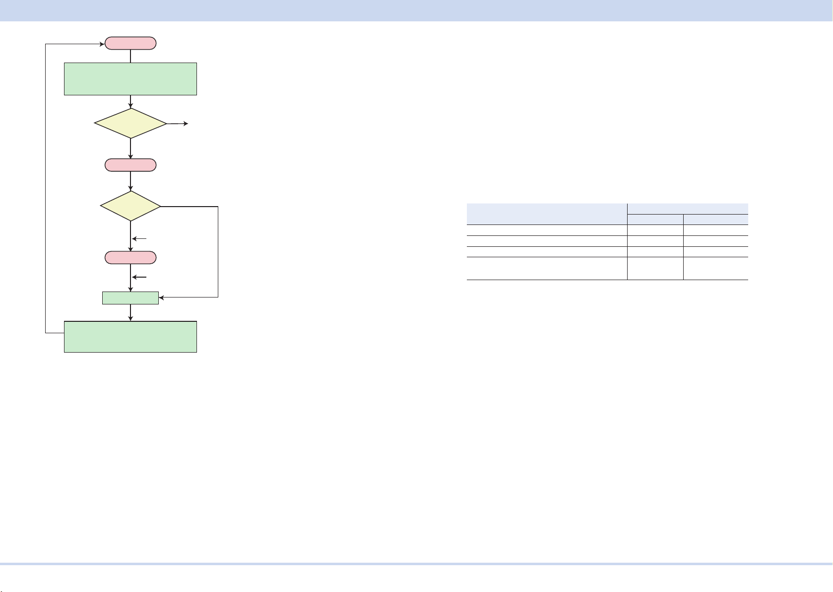
Voltage: 110 V, Frequency: 60 Hz
Reserved frequency: 50 Hz
the sequence 1 trigger function
IDLE
Reserved voltage100 V
Reserved frequency: 50 Hz
FIX
IMM
Send the
INIT:TRAN
Send the
TRIG:TRAN
VOLT:MODE?
FREQ:MODE?
STEP
INITiated
TRIG:SOURce?
BUS
WTG
Output change
When mode of trigger is FIX,
is disabled even if you send
INIT or TRIG.
Tutorial
TRANsient subsystem.
You can also use the *TRG command or the IEEE488.1 get (Group Execute Trigger)
command for the same purpose. This command applies a software trigger to the
TRANsient subsystem and ACQuire subsystem, so if there are other trigger subsystem that are in the INITiated state, their sequences will also be executed at the same
time.
Operation using a software trigger
When ABOR is sent, INIT:TRAN is cancelled. The VOLT:TRIG setting does not
change.
The following table shows the responses when the voltage is set to 20 V (VOLT
20)
and when the target value to which the voltage will change when a trigger is received
is set to 10 V (VOLT
Immediately after the setting is made. 20 V 10 V
After a trigger is sent. 10 V 10 V
After *RST is sent. 0 V 0 V
When "VOLT 30" (to change the voltage) is
sent before sending a trigger
:TRIG 10).
Response
VOLT? VOLT:TRIG?
30 V 30 V (cancel)
Voltage: 100 V, Frequency: 50 Hz
Reserved voltage: 100 V
The TRIGger:TRANsient:SOURce command sets the trigger source to BUS or IMMe-
diate.
When the Trigger Source is set to IMMediate, the change is executed immediately
causing the voltage and/or frequency to change to a new setting. When the T
Source is set to BUS, the trigger subsystem goes to the WTG (Waiting For
rigger
Trigger)
state. When a software trigger is applied with the TRIGger:TRANsient:IMMediate or
*TRG command, the change is executed.
When the operation is completed, the trigger subsystem returns to the IDLE state
again. When an ABORt or an equivalent command is sent without executing the
trigger, the change is cancelled, and then the trigger subsystem returns to the IDLE
state.
Setting items that are programmable in the TRANsient subsystem are VOLTage,
VOLTage:OFFSet, and FREQuency. CURRent limit settings are not associated with
the trigger subsystem.
The TRIGger:TRANsient:IMMediate command applies a software trigger to the
KIKUSUI Electronics Corp. PCR-MA Interface Manual
Page 67

Tutorial
Measurement (ACQuire)
PCR-MA has three different trigger subsystems -TRANsient, ACQuire, and SYNChronize.
The ACQuire subsystem is the measurement trigger subsystem. This subsystem is
used to measure values such as voltage, current, and power.
There are easy measurements and advanced measurements.
■ Easy Measurement
The PCR-MA has the capability to return voltage, current, and power measurement
values. The easiest way is use the MEASure commands.
The MEASure commands immediately start a new measurement. This is the easiest
way to make measurements, however simultaneity for multi-item measurements are
lost, because each MEASure command starts a new measurement. To avoid this,
consider the advanced measurement approach that is described later in this manual,
allowing separate control for measurement initiation and data query.
Voltage/Current Measurement
In AC mode, use the AC measurement queries.
MEASure:VOLTage:AC? ‘Queries AC voltage in volts-rms
MEASure:CURRent:AC? ‘Queries AC current in amps-rms
In DC mode, use the DC measurement queries.
MEASure:VOLTage:DC? ‘Queries DC voltage in volts
MEASure:CURRent:DC? ‘Queries DC current in amps
AC or DC output mode.
Normally, it takes approximately 330 ms to complete a single measurement. This
means that sending MEASure queries multiple times requires long data acquisition
time. If you want to acquire multiple items, it is recommended that you use the ad-
vanced approach described later.
The PCR-MA supports READ commands that also initiate a new measurement and
data query, however, READ and MEASure operate exactly the same, as they are
aliases.
Power Measurement
In AC mode, use the AC measurement queries.
MEASure:POWer:AC? ‘Queries AC real power in watts
MEASure:POWer:AC:APParent? ‘Queries AC apparent power in volt-amps
MEASure:POWer:AC:REACtive? ‘Queries AC reactive power in volt-amps-reac-
tive
MEASure:POWer:AC:PFACtor? ‘Queries AC power factor
In DC mode, use the DC measurement queries.
MEASure:POWer:DC? ‘Queries DC power in watts
The current measurement function also has the following additional items:
MEASure:CURRent:AMPLitude:MAXimum? ‘Queries peak current in amps
MEASure:CURRent:AMPLitude:MAXimum:HOLD? ‘Queries peak current (the held
value)
MEASure:CURRent:CREStfactor? ‘Queries crest factor
The MEASure:CURRent:AMPLitude:MAXimum:HOLD command queries the maximum peak current since the PCR-MA was turned on or since it was explicitly cleared.
To clear the peak current (held value), use the SENSe:CURRent:PEAK:CLEar com-
mand.
SENSe:CURRent:PEAK:CLEar
By *RST and *RCL default, the peak current (held value) is not cleared.
Available measurement items vary depending on the selected output mode. For example, DC measurement cannot be performed while AC mode is selected.
Peak current measurement and peak hold measurement can be performed in either
KIKUSUI Electronics Corp. PCR-MA Interface Manual
Page 68
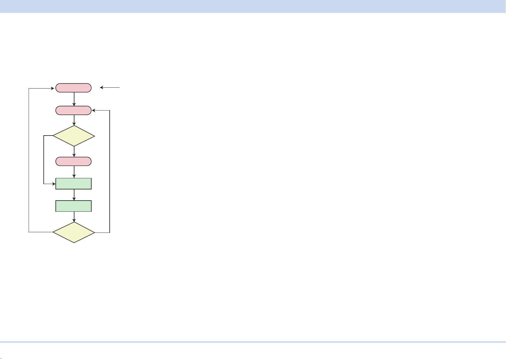
Tutorial
■ Advanced Measurement
In advanced measurement, you can separate and control the starting of measure-
ment and the referencing of data.
State
The three states are available in the sequence operation.-> Tutorial “State of Trigger
subsystem”
Send the ABOR/*RST/*RCL
When :INIT:CONT is ON, send the
:INIT:CONT OFF; :ABOR insted of the
ABOR
IMM
TRIG:SOURce?
Measurement
Measurement
is completed
CONTinuous?
IDLE
Send the INIIT
INITiated
BUS
WTG
Gives a software
trigger
is started
ONOFF
Voltage/Current/Power Measurement
To start a new measurement, set the trigger source to IMMediate and use the INITiate
command.
TRIGger:ACQuire:SOURce IMMediate ‘Selects trigger source to IMMediate
INITiate:ACQuire ‘Initiates ACQuire subsystem
When the measurement is completed, measurement data can be queried with the
FETCh query commands.
FETCh:VOLTage:AC? ‘Queries AC voltage in volts, without new measure
FETCh:CURRent:AC? ‘Queries AC current in amps, without new measure
FETCh:POWer:AC? ‘Queries AC real power in watts, without new measure
FETCh:POWer:AC:APParent? ‘Queries AC apparent power in volt-amps, without
new measure
If you send a FETCh command before the measurement is complete, correct measurement data will not be obtained. By using the *OPC command, you can obtain
correct measurement data. -> Tutorial “Waiting for Operation Complete”
:INITiate:ACQuire;*OPC ‘Initiate ACQuire subsystem and wait for the measure-
ment to complete.
The TRIGger:ACQuire:SOURce command sets the trigger source to BUS or IMMediate. The INITiate:ACQuire command makes the ACQuire subsystem leave the IDLE
state and go the initiated state.
When the Trigger Source is set to IMMediate, the action is executed immediately
causing a new measurement to start. When the Trigger Source is set to BUS, the
ACQuire subsystem goes to the WTG (Waiting For Trigger) state. When a software
trigger is applied with the TRIGger:ACQuire or *TRG command, the measurement
action is executed. When the operation is completed, the ACQuire subsystem returns
to the IDLE state again. When an ABORt or an equivalent command is sent without
executing the trigger, the measurement action is cancelled, and then the ACQuire
subsystem returns to the IDLE state.
The ABORt command and IEEE488.1 sdc/dcl commands simply abort the measurement task that is in progress. It does not have a feature to invalidate any measurement data that has been acquired. On the other hand, the *RST and *RCL commands
not only abort the measurement task, but also invalidate the acquired measurement
data. This means that the “*RST;:FETC:VOLT:AC?” command line will generate an error, because no measurement data can be fetched and there is no new measurement
is scheduled.
The only difference between MEASure and FETCh commands is that the MEASure
command starts a new measurement while the FETCh command does not. A
vailabil-
ity for measurement items varies depending on the output mode, but it is exactly the
same for MEASure and FETCh.
If you want the ACQuire subsystem to start the measurement on a software trigger,
change the trigger source to BUS.
TRIGger:ACQuire:SOURce BUS ‘Selects trigger source to BUS
INITiate:ACQuire ‘Initiates ACQuire subsystem
TRIGger:ACQuire ‘Applies a software trigger to ACQuire subsystem
KIKUSUI Electronics Corp. PCR-MA Interface Manual
Page 69

Tutorial
■ Auto continue mode
If auto continue mode is turned on, measured data is automatically refreshed without
having to send the INIT command each time. In normal cases, turn auto continue
mode off (default).
When the sequence operation auto continue mode is turned on
When the trigger source is set to IMMediate, the measurement starts immediately.
When the operation completes, the measurement starts automatically. However
auto continue mode is on, the MEASure, READ, and FETCh queries operate in the
same manner.
measurement results, and simultaneity is lost.
When the trigger source is set to BUS, the PCR-MA waits for a software trigger
before making the measurement. When the operation has completed, the PCR-MA
waits for the next trigger.
The ABORt command to the measurement function is invalid, because the trigger
subsystem automatically exits the IDLE state even if aborted. The *RST/*RCL com-
mand resets the continuous operation to off.
When the sequence operation auto continue mode is turned off
The measurement currently in progress continues unless ABOR is sent. The operation does not automatically continue to the new change or measurement.
This means that sending multiple FETCh queries results in different
, if
Output-on Phase Control (SYNChronize)
PCR-MA has three different trigger subsystems -TRANsient, ACQuire, and SYNChronize.
The SYNChronize subsystem is the output ON phase control trigger subsystem.
Using SYNChronize subsystem allows you to synchronize the output ON changes
with a specic AC output phase angle.
TRIGger:SYNChronize:SOURce PHASe ‘Congures the PCR-MA so that the
phase will be controlled when the output is turned on
TRIGger:SYNChronize:PHASe 270 ‘Sets the phase angle at 270 deg
OUTPut ON ‘Turns the output on
When the power supply output is changed from OFF to ON state, the changing action
is synchronized to the specied phase angle.
To disable the output-on phase control, set the trigger source to IMMediate.
TRIGger:SYNChronize:SOURce IMMediate
The output-on phase control is applied only when the output is changed from OFF to
ON. It is not applied when the output changes from ON to OFF or when other settings
such as the AC voltage setting, DC voltage setting, and frequency setting change.
The output-on phase control is not a function that synchronizes the output frequency
to the input commercial AC line.
The SYNChronize subsystem does not have INITiate commands. It is always initiated
and cannot be aborted.
KIKUSUI Electronics Corp. PCR-MA Interface Manual
Page 70

Tutorial
Waiting for Operation Complete
The *OPC command has a capability to wait for an operation to complete. Operation
complete means that there is no pending operation that is still in progress. It takes
approximately 110 ms for a measurement to be completed. The PCR-MA is not in the
operation complete state while a measurement is ongoing. When the measurement
completes, if there are no other operations waiting to be completed, the PCR-MA
enters the operation complete state.
When the *OPC command is sent, the PCR-MA enters the Operation Complete
Command Active State (OCAS). When the measurement is completed and there is
no other operation pending, the PCR-MA returns to Operation Complete Command
Idle State (OCIS) and sets the OPC bit (bit 0) to TRUE (1) in the Standard Event
Status Register. This information can be conrmed with the *ESR? query command
by checking the OPC bit (bit 0).
The following example makes a new measurement and sends the *OPC. When the
measurement is completed, an SRQ (Service Request) is generated, as the Standard
Event Status Enable Register and the Service Request Enable Register are unmasked so that an SRQ can be signaled by the Operation Complete event.
*ESE 1;*SRE 32;*CLS;:INITiate:IMMediate:ACQuire;*OPC
<Wait for the SRQ to be generated.>
Using the *OPC? query command instead of the *OPC command makes the PCRMA enter the Operation Complete Query Active State (OQAS). When the measurement is completed and there is no other operation pending, the PCR-MA returns to
the Operation Complete Query Idle State (OQIS) and sets the response data to “1” (in
NR1 format ) in the output queue.
INITiate:IMMediate:ACQuire;*OPC?
<Read the response>
At power-on or after the IEEE488 sdc/dcl, *RST command is sent, the PCR-MA is in
the OCIS and OQIS state
Status Monitoring
The PCR-MA has two mandatory SCPI standard registers, STATus:OPERation and
STATus:QUEStionable, in addition to the IEEE488.2 standard registers.
■ Register basics
All SCPI registers have standard event/lter architecture, employing CONDition,
EVENt, ENABle, and optionally PTRansition and NTRansition. CONDition and EVENt
are read-only registers working as status indicators, and ENABle, PTRansition and
NTRansition are read-write registers working as event and summary lters.
■ STATus:OPERation
The STATus:OPERation register records events or signals that occur during normal
operation.
For example, to check if the PCR-MA is being regulated in CV state, check the CV bit
(bit 8) on the STATus:OPERation register.
STATus:OPERation?
■ STATus:QUEStionable
The STATus:QUEStionable register records events or signals that indicate abnormal
operation.
To check if the protection function is working, check the OV bit (bit 0) on the STATus:
QUEStionable register.
STATus:QUEStionable?
'Check whether the CV bit is set
'Check whether the OV bit is set
KIKUSUI Electronics Corp. PCR-MA Interface Manual
Page 71

Tutorial
■ PON (Power ON) bit
The PON bit (bit 7) in the event status register is set whenever the PCR-MA is turned
on. The most common use for the PON bit is to generate an SRQ at power-on to
keep track of unexpected loss of power or power line failure. To do this, follow the
steps shown below.
Set *PSC (Power-on Status Clear) to 0 (or OFF).
1
Enable the backup function of the event status enable register and service request enable register (*PSC 0).
Set the PON bit (bit 7) of the event status enable register.
2
Permit the transmission of a power-on event to the upper layer (*ESE 128).
Set the ESB bit (bit 5) of the status byte enable register.
3
Permit the generation of an SRQ caused by a standard event (*SRE 32).
*PSC 0;*ESE 128;*SRE 32
Though the SRQ feature itself is provided by communication protocol on the USB
interface or LAN (VXI-11/ HiSLIP) interface, a Connection Lost error in the VISA I/O
session occurs immediately before the power-on event. It may be difcult to handle
PON events when using the USB/LAN interface.
Error Checking
■ Error/event queue
The SCPI specications dene a standard error reporting scheme, Error/Event
Queue. This is a FIFO (First In First Out) queue, which records errors and events.
The maximum number of errors/events that the PCR-MA can record is 255. Each
error/event can be read with the SYSTem:ERRor query.
SYSTem:ERRor?
The response to this query contains a numeric part (error/event number) and a textual description, such as:
-222,"Data out of range"
The error/event queue is empty when the *CLS common command is sent, when the
last item in the queue is read, and when the PCR-MA is turned on. When the error/
event queue is empty, the query returns the following:
0,"No error"
■ Displaying communication errors
The PCR-MA has a debug trace function. The oldest item among the errors and
events (if they are present) can be displayed on the PCR-MA. This function is convenient when you debug your remote applications.
While an error/event item is displayed on the panel, the normal voltmeter and amme-
ter are disabled.
If the error/event queue is empty, the debug trace function does not display any errors. Sending the *CLS command clears the communication error display.
If in local mode, the debug trace function is temporarily disabled.
The communication error display can be enabled or disabled with the SYSTem:CONFigure:TRACe command.
SYSTem:CONFigure:TRACe {ON|OFF}
KIKUSUI Electronics Corp. PCR-MA Interface Manual
Page 72
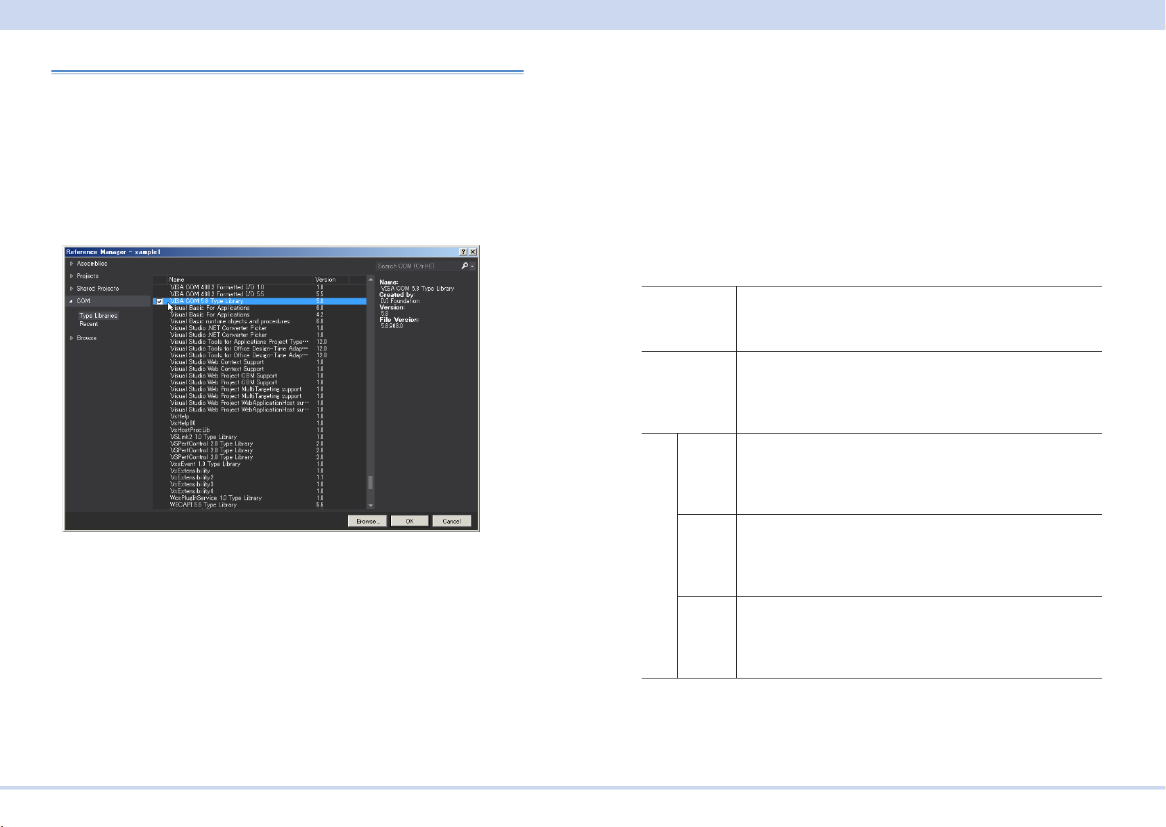
Tutorial
Visual Basic 2017
■ Setting the "Project"
First, add the communication middleware (VISA library) to the project.
Click References on the Project menu to open the Reference Manager window.
On the navigation pane, click COM and then Type Libraries.
From the list in the center of the window, select “VISA COM *.* Type Library” (where *.*
is the VISA library version number), and select the check box.
Click OK to close the dialog box.
■ Communication through GPIB, USB, or LAN
Open the VISA
To communicate with an GPIB, USB, or LAN device using VISA, you have to rst
open VISA. When you open VISA, specify the I/O resource.
Example : To open VISA by using USB
Set rm = CreateObject("VISA.GlobalRM")
Set msg = rm.Open("USB::0x0B3E::0x1050::00000001::INSTR", NO_LOCK, 0, "")
"USB::0x0B3E::0x1050::00000001::INSTR" is the I/O resource.
The I/O resource is specied by the following constructions. The part indicated with [ ]
can be omitted. Enter the appropriate values in the parts specied in oblique charac-
ters.
GPIB GPIB[board]::PrimaryAddress[::SecondaryAddress][::INSTR]
Example: The primary address 3 of the measuring instrument connected
to GPIB0.
GPIB0::3::INSTR
USB USB[board]::VendorID::ProductID::SerialNumber[::InterfaceNumber]
[::INSTR]
Example: The USNTMC measuring instrument having vendor ID (VID)
2878, Product ID (PID) 4176 and serial number "00000001."
*1
LAN
VXI-11 TCPIP[board]::hostname[::inst0][::INSTR]
HiSLIP TCPIP[board]::hostname::hislip0[::INSTR]
SCPI-RAW TCPIP[board]::hostname::portno::SOCKET
*1
: The hostname must be a valid mDNS hostname (a Bonjour hostname that ends in ".local") or
a DNS hostname that is managed by an external DNS server (a full-qualied domain name—
FQDN). If you are using an mDNS hostname, Apple Bonjour (alternatively, iTunes or Safari)
must be installed on your PC.
USB0::0x0B3E::0x1050::00000001::INSTR
Example :The measuring instrument whose IP address (hostname) is
169.254.7.8.
TCPIP::169.254.7.8::INSTR
You can also set the LAN device name using the host name.
Example :The measuring instrument whose IP address (hostname) is
169.254.7.8.
TCPIP::169.254.7.8::hislip0::INSTR
You can also set the LAN device name using the host name.
Example :The measuring instrument whose IP address (hostname) is
169.254.7.8. (The "portno" setting of the PCR-MA is always 5025.)
TCPIP::169.254.7.8::5025::SOCKET
You can also set the LAN device name using the host name.
For VISA, the alias can be used for the I/O resource.
KIKUSUI Electronics Corp. PCR-MA Interface Manual
Page 73

Tutorial
When using the alias for the I/O resource, even if the alias name is hard-coded directly in the application, the alias name can be easily converted to the appropriate I/O
resource name.
Example : When using the alias (MYDEV1) for the I/O resource.
Set msg = rm.Open("MYDEV1", NO_LOCK, 0, "")
When the alias is used, the actual I/O resource is specied by an external conguration table. When using USB (example for KI-VISA):
Please refer to the applicable VISA manual.
Controlling the devices
Next, use "Read" and "Write" commands to control devices. You must include line-
feed codes in the command strings.
Example:
msg.WriteString (“VOLT 110” & vbLF) ‘Set the AC voltage to 110 V
msg.WriteString (“FREQ 60” & vbLF) ‘Set the frequency to 60.0 Hz
msg.WriteString (“OUTP 1” & vbLF) ‘Turn the output on
Closing the VISA
Close the VISA at the end.
You only need to include one "open" VISA command and one "close" VISA command
in the program.
msg.Close
■ Sample program
Imports Ivi.Visa.Interop
Public Class Form1
Dim rm As ResourceManager
Dim msg As IMessage
Sub Form1_Load(ByVal sender As System.Object, ByVal e As System.EventArgs) Handles MyBase.Load
rm = CreateObject("VISA.GlobalRM")
msg = rm.Open("USB0::0x0B3E::0x1050::00000001::INSTR", AccessMode.NO_LOCK, 0, "")
'Example: GPIB
'msg = rm.Open("GPIB0::1::INSTR", AccessMode.NO_LOCK, 0, "")
'Example: Using an VISA alias
'msg = rm.Open("MYDEV1", AccessMode.NO_LOCK, 0, "")
'Example: LAN(SCPI-RAW)
'msg = rm.Open("TCPIP::169.254.7.8::5025::SOCKET", AccessMode.NO_LOCK, 0, "")
msg.TerminationCharacterEnabled = True
End Sub
'Query the instrument identity
Private Sub Button1_Click(ByVal sender As System.Object, ByVal e As System.EventArgs) Handles Button1.Click
msg.WriteString("*IDN?" & vbLf)
TextBox1.Text = msg.ReadString(256)
End Sub
'Set the voltage and frequency
Private Sub Button2_Click(ByVal sender As System.Object, ByVal e As System.EventArgs) Handles Button2.Click
msg.WriteString("OUTP 0" & vbLf)
msg.WriteString("VOLT 110" & vbLf)
msg.WriteString("FREQ 60" & vbLf)
msg.WriteString("OUTP 1" & vbLf)
End Sub
KIKUSUI Electronics Corp. PCR-MA Interface Manual
Page 74

'Querys measurement DC voltage
Private Sub Button3_Click(ByVal sender As System.Object, ByVal e As System.EventArgs) Handles Button3.Click
msg.WriteString("MEAS:VOLT:DC?" & vbLf)
TextBox1.Text = msg.ReadString(256)
End Sub
Private Sub Form1_Disposed(ByVal sender As Object, ByVal e As System.EventArgs) Handles Me.Disposed
msg.Close()
End Sub
End Class
Tutorial
KIKUSUI Electronics Corp. PCR-MA Interface Manual
 Loading...