

Page 1
PART NO. Z1-005-860, IB026165
Jan. 2016
1.2 kW model
PBZ20-60 SR
PBZ40-30 SR
PBZ60-20.1 SR
PBZ80-15 SR
1.6 kW model
PBZ20-80 SR
PBZ40-40 SR
PBZ60-26.8 SR
PBZ80-20 SR
2 kW model
PBZ20-100 SR
PBZ40-50 SR
PBZ60-33.5 SR
PBZ80-25 SR
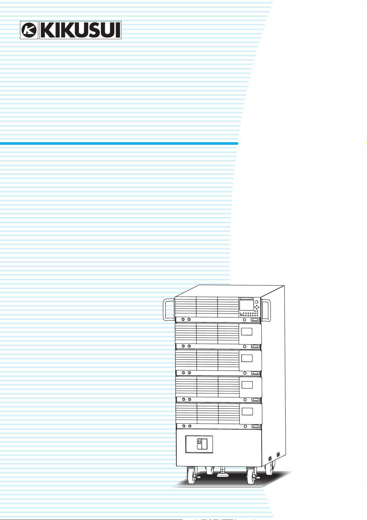
Setup Guide
Large-Capacity Bipolar Power Supply
Smart Rack System
PBZ-SR Series
Checking the Package Contents 3
Product Overview 3
Option 3
Part Names 5
Preparation 6
Connecting the Power Cable 6
Turning On 8
Turning Off 10
Connecting the Load 11
Connecting the Load Cable 11
Using Remote Sensing 15
Connecting External Devices 19
Connecting an External Controller 19
Connecting an Remote Controller 21
Connecting Devices to Synchronize 22
Connecting an External Signal Source 23
Using Current Monitor Output 23
Page 2
KIKUSUI ELECTRONICS CORP.
1-1-3, Higashiyamata, Tsuzuki-ku,
Yokohama, 224-0023, Japan
TEL: +81-45-593-7570 Fax: +81-45-593-7571
http://www.kikusui.co.jp/en
WEBSITE
The newest version of the PBZ-SR series manuals can be downloaded from
Download service of Kikusui website.
Thank you for purchasing the PBZ-SR Series Large-Capacity
About PBZ-SR Series Manuals
Paper
Paper
PDF
PDF
PDF
PDF
PDF
Bipolar Power Supply.
There are PBZ-SR series Manuals listed as follows.
Product firmware versions
This manual applies to products with firmware versions 2.2X.
When contacting us about the product, please provide us with:
The model (marked in the top section of the front panel)
The firmware version (see page 8)
The serial number (marked in the bottom section of the rear
panel)
• Setup Guide (this manual)
PDF
This manual is intended for users who are using the PBZSR Series for the first time. It includes covers topics related
to setting up the product such as installing the product,
wiring the power cables and load cables, and connecting
the connectors.
• Specifications
This document describes the specifications of the PBZ-SR
series.
• User's Manual of base model PBZ-SR series
This manual describes the base model PBZ-SR series. It
provides an overview of the base model and notes on
usage. It also gives various settings, operation procedures,
maintenance and so on.
Read first the setup guide to set up the PBZ-SR series, next
read the User's Manual to use the functions of the product
effectively.
• Quick Reference of base model PBZ-SR series
Paper
Paper
This manual explains Panel description and operation briefly.
• The communication interface manual
This manual contains details about remotely controlling the
tester using SCPI commands. The interface manual is
written for readers with sufficient basic knowledge of how to
control measuring instruments using a PC.
• Safety Information
Paper
Paper
This document contains general safety precautions for this
product. Keep them in mind and make sure to observe
them.
The PBZ-SR series Manuals are intended for users of the
product or persons teaching other users on how to operate the
product.
Explanations are given under the presumption that the reader
has knowledge about Power Supply.
PDF is provided on the included CD-ROM.
Adobe Reader 9.2 or later is required to view the PDF file.
If you find any incorrectly arranged or missing pages in the
manual, they will be replaced. If the manual gets lost or soiled,
a new copy can be provided for a fee. In either case, please
contact Kikusui distributor/agent, and provide the “Kikusui Part
No.” given on the cover.
The PBZ-SR series Manuals has been prepared with the
utmost care; however, if you have any questions, or note any
errors or omissions, please contact Kikusui distributor/agent.
After reading, always keep the manual nearby so that you may
refer to it as needed.
Page 3
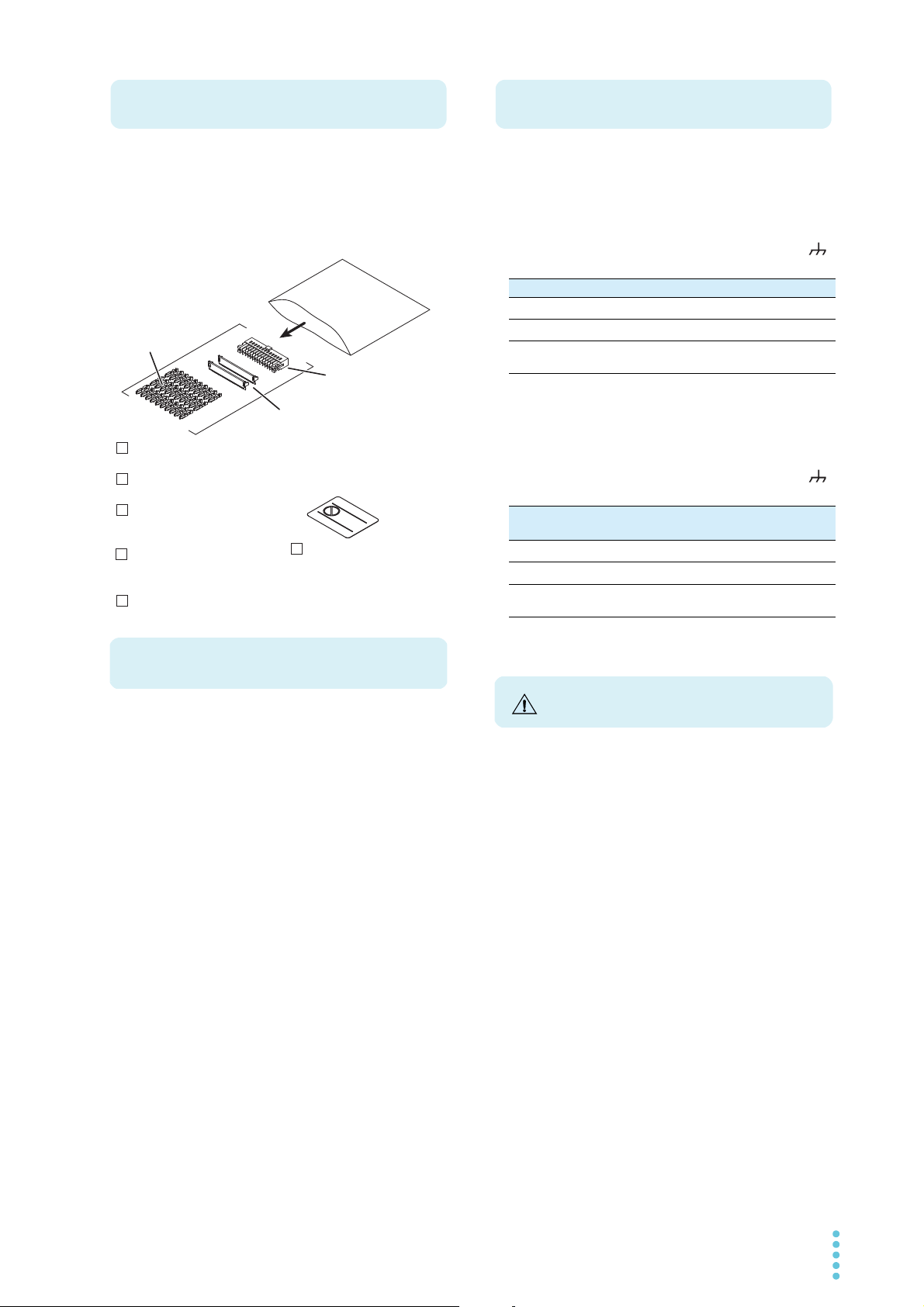
When you receive the product, check that all accessories are
Checking the Package Contents
Setup guide
(This manual, 1 pc.)
CD-ROM (1 pc.)
Quick Reference
English:1 pc., Japanese:1 pc.
Pins (30 pcs.)
[84-49-0100]
Socket (1 pc.)
[84-49-0160]
Protection cover (2 sets)
[84-49-0161]
J1 connector kit (1 set)
Safety information (1 pc.)
If necessary, attach
to the product.
Heavy object warning
label (1 pc.)
[A8-900-158]
Product Overview
Option
Precautions for Installation
included and that the accessories have not been damaged
during transportation.
If any of the accessories are damaged or missing, contact
your Kikusui agent or distributor.
We recommend that all packing materials be saved, in case
the product needs to be transported at a later date.
The PBZ-SR has the following options. For information about
options, contact your Kikusui agent or distributor.
• AC Input power cable (AC8-3P3M-M5C)
8sq Heavy PVC jacketed three-core cable 3 m
• Low Inductance Cable (TL02-PLZ, TL03-PLZ)
When you connect the cable to the output terminal block of
the PBZ-SR, be sure to provide grounding through the
terminal.
TL02-PLZ TL03-PLZ
Full length
Inductance value
Maximum allowable
current
*1. Between the insulation caps
*2. at 100 kHz
• Low Inductance Cable
(LIC40-2P1M-M6M6, LIC40-2P2M-M6M6)
When you connect the cable to the output terminal block of
the PBZ-SR, be sure to provide grounding through the
terminal.
Full length
Inductance value
Maximum allowable
current
*1. Between the insulation caps
*2. at 100 kHz
*1
*1
1000 mm 2000 mm
*2
150 nH 200 nH
100 A
LIC40-2P1MM6M6
1000 mm 2000 mm
*2
150 nH 200 nH
LIC40-2P2MM6M6
50 A
The PBZ-SR series is a large-capacity bipolar regulated DC
power supply. It is a large-current model consisting of PBZ
series bipolar power supplies that are mounted using
dedicated rack parts (smart rack).
• It supports four-quadrant output, which means that it can
source and sink both positive and negative voltages and
currents.
• The internal AC signal or an external signal can be superimposed on the DC output.
• You can use the sequence feature to generate test signals
for automotive and other electronic devices.
• Additionally, the PBZ-SR can be used with a variety of loads
to perform tests such as motor endurance tests, solenoid
operation tests, and capacitor ripple tests.
• You can control the PBZ-SR series externally using external
analog signals and control it remotely using RS232C, GPIB,
USB, and LAN communication features.
When installing this product, be sure to observe the
precautions provided in “Precautions Concerning Installation
Location” in the Safety information manual. Items specific to
this product are given below.
• Avoid locations where the product is exposed to high temperature or direct sunlight.
Do not install the product near a heater or in areas subject
to drastic temperature changes.
Operating temperature range: 0°C to +40°C (32°F to +104°F)
Storage temperature range: -25
• Avoid humid environments.
Do not install the product in high-humidity locations–near a
boiler, humidifier, or water supply.
Operating humidity range: 20 %rh to 85 %rh (no condensation)
Storage humidity range: 90 %rh or less (no condensation)
Condensation may occur even within the operating relative
humidity range. If this happens, do not use the product until
the condensation dries up completely.
• The PBZ-SR series does not allow individual PBZs to be
operated separately. Using them separately is outside the
scope of the warranty.
°
C to +70°C (-13°F to +158°F)
PBZ-SR 3
Page 4
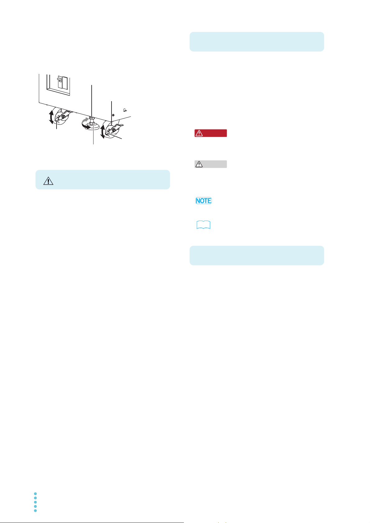
When fixing the power supply at the
Rock
Free
Caster lock
Stopper bolt's bottom nut (M12)
x Turn the nut clockwise to lower the stopper (lock).
x Turn the nut counterclockwise to raise the stopper (unlock)
Stopper bolt's top nut (M12)
x When the stopper bolt is locked, turn
the nut clockwise to fix the stopper
position in place.
Caster lock
Precautions for Moving
Notations Used in This Manual
WARNING
CAUTION
Contents of the Included CD-ROM
installation location
This product has casters on its bottom side, so it is easy to
move the product. To ensure that the product is not moved
accidentally while it is being operated, use the stopper to fix
the product in place, and lock the casters.
When installing this product, be sure to observe the
precautions provided in “Precautions to Be Taken When
Moving the Product” in the Safety information manual. Items
specific to this product are given below.
• The rear, side and top panel may become hot during operation. If you touch it, you may burn yourself.
• If the power supply is fixed in place with the stopper, release
the stopper. Otherwise, it may cause injuries due to the
power supply falling over.
• When using a forklift to move the power supply, place the
fork underneath the power supply and confirm all safety
conditions before lifting. When lifting the power supply with
a crane using lifting bands, always apply the bands at the
equipment bottom and confirm all safety conditions before
lifting.
• Do not lift the power supply using the handles. The handles
are used to grab the power supply when moving power supply on the casters. The handles are not strong enough to
support the weight of the power supply.
• Do not lay the power supply with its side up or place the
power supply upside-down.
• The large-capacity bipolar power supplies smart rack system PBZ20-60 SR, PBZ20-80 SR, PBZ20-100 SR, PBZ4030 SR, PBZ40-40 SR, PBZ40-50 SR, PBZ60-20.1 SR,
PBZ60-26.8 SR, PBZ60-33.5 SR, PBZ80-15 SR, PBZ80-20
SR, and PBZ80-25 SR are also referred to as the PBZ-SR
and PBZ-SR series respectively.
• The bipolar power supplies (the individual power supplies)
PBZ20-20, PBZ40-10, PBZ60-6.7 and PBZ80-5 are also
referred to as the PBZ series respectively.
• The following markings are used in this manual.
Indicates a potentially hazardous situation which, if
ignored, could result in death or serious injury.
.
Indicates a potentially hazardous situation which, if
ignored, may result in damage to the product or other
property.
Indicates information that you should know.
See
Indicates reference to detailed information.
Insert the program CD-ROM in the drive. The menu program
window will appear momentarily. If the menu program window
does not appear, open the CD-ROM folder in Windows
Explorer, and then double-click index.htm to start the menu
program.
Accompanying CD-ROM contains following the items.
•IVI-COM Driver
• KI-VISA Driver
• PBZ-SR series Setup Guide (PDF)
• PBZ-SR series Specifications (PDF)
• PBZ series User’s Manual (PDF)
• PBZ series Quick Reference (PDF)
• PBZ series Communication interface manual (PDF))
• Safety Information (PDF)
4 PBZ-SR
Page 5
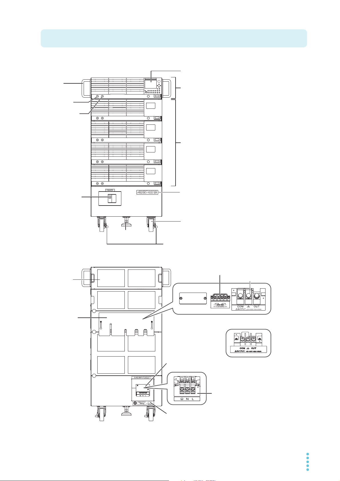
Front panel (example of PBZ20-100 SR)
Part Names
POWER switch
Caster
Caster lock
Stopper bolt
Slave unit
Model name
Master unit
Display
Handle
* The PBZ-SR series does not have the
OUTPUT terminals that are available on
the front panel of individual PBZ power
supplies.
EXT SIG IN
terminal
I MON terminal
*TheoutputterminalblockonthePBZ60-XXSR
seriesandPBZ80-XXSRseriesisfixedwith
screws.
Rear Panel
Output
terminal cover
(Cover opened)
(Cover opened)
Sensing terminals
AC input terminal cover
AC input terminals
Output terminals
Serial number
Rear panel (example of PBZ20-100 SR)
PBZ-SR 5
Page 6
1
WARNING
See
Preparation
This chapter describes how to connect the power cable and how to turn the power on and off.
Connecting the Power Cable
This product is designed as an equipment of IEC Overvoltage Category II (energy-consuming
equipment supplied from the fixed installation)
.
• Be sure to have a qualified engineer connect the power cable to the distribution
board.
• Install the AC power cord such that the distance between the power supply and the
switch on the switchboard is within 3 m. This procedure facilitates operation of the
switch on the switchboard in the event of emergency.
If the distance to the switch on the switchboard is to be 3 m or more, install the AC
power cord with a separate switch provided within 3 m from the power supply. For
such a switch, use one with two poles that can be disconnected simultaneously.
Possible electric shock.
• This product is an IEC Safety Class I equipment (equipment with a protective
conductor terminal). Be sure to ground the product to prevent electric shock.
• Connect the ground terminal to earth ground.
p. 3
A power cable is not supplied with the PBZ-SR series. Use the optional AC input power cable
(AC8-3P3M-M5C).
If you will not use the optional power cable, prepare an appropriate power cable with a
nominal cross-sectional area of at least AWG8 (8 mm
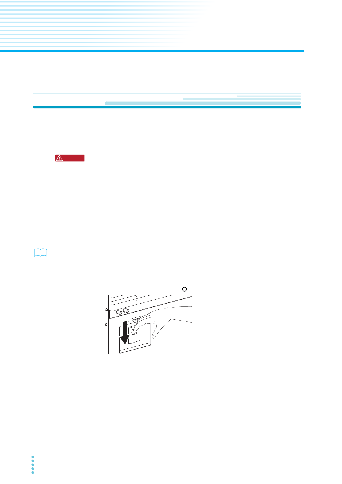
Turn the POWER switch off ( ).
1
Check that the AC power line complies with the input rating of the
2
product.
The voltage that can be applied is any of the nominal power supply voltages in the
range of 200 Vac to 240 Vac. The frequency is 50 Hz or 60 Hz (frequency range of
47 Hz to 63 Hz).
2
).
6 PBZ-SR
Page 7
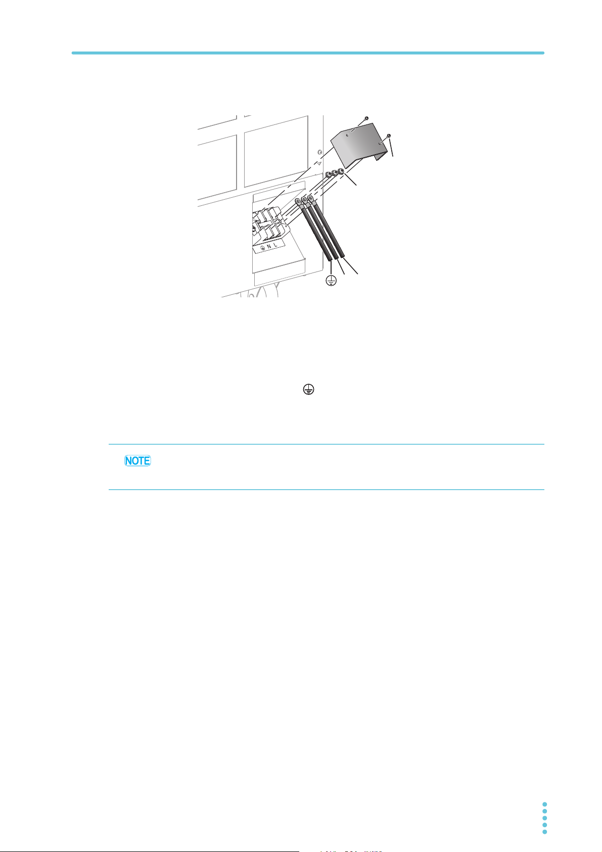
Connecting the Power Cable
LN
(GND)
Screw (M5)
Screw (M3)
Connect the power cable to the AC input terminal
3
The size of the terminal block screws is M5. Attach appropriate crimping terminals to
the power cable.
Attach crimping terminals to the switchboard end of the power cable.
4
Use crimping terminals that conform to the switchboard's terminal
screws.
Turn off the switchboard’s breaker.
5
Connect the N, L, and (GND) wires of the power cable to the matching
6
terminals on the switchboard.
Be sure to connect the GND terminal of the AC INPUT terminal block to the GND
terminal of the switchboard.
The POWER switch can be used to disconnect the product from the AC power line in an
emergency. Provide enough space around the POWER switch to ensure that it can be
turned off at any time.
PBZ-SR 7
Page 8
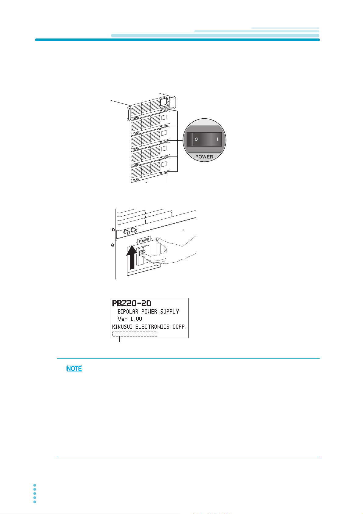
Turning On
SELF TEST . . .
PASS (When the test passes)
SELF TEST . . .
E101 (When an error is detected)
(Display example)
Check that the power cable is correctly connected.
1
Check that the POWER switches on the individual PBZ power supplies
2
are all turned on.
Turn the POWER switch on.
3
PBZ20-100 SR example
The display shows the model and firmware version, and a self test starts.
When the self test finishes, if no errors
were detected, “PASS” is displayed. If an
error was detected, the error number is
displayed.
• If you notice strange sounds, unusual odors, fire, or smoke around or from inside the PBZSR, lower the POWER switch lever to turn the power off.
• When you turn the POWER switch on for the first time after purchase, the PBZ-SR starts
with its default values. For details on the default values, See "Initial Settings" on page 10 .
• If you want to turn on the POWER switch of the PBZ-SR first and then the POWER
switches of the individual PBZ power supplies, turn on the slave units first.
• The circuit breaker used in the POWER switch of the PBZ-SR is indicated below.
EW32AAG-2P032BX (72-08-2800) Rated current: 32 A
Rated current sensitivity: 30 mA
• If the display shows “ALARM,” an OVP (overvoltage protection), OCP (overcurrent
protection), or OHP (overheat protection) is activated. Remove the root cause of the alarm.
For details on the OVP, OCP and OHP, refer to the “Protection Features and Alarms” in
PBZ series User’s Manual.
8 PBZ-SR
Page 9

When the PBZ-SR Does Not Start Properly
If an error number is displayed after the self test
Follow the remedy that corresponds to the appropriate error number shown in the following
table. If following the remedy shown here does not solve the problem, contact your Kikusui
agent or distributor.
Turning On
Error
number
E101 CALIBRATION DATA An error was detected in the calibration values.
E102 EEPROM DATA An error was detected in the backup data.
E901 INTERNAL ERROR An error was detected in the internal system.
If you initialize the PBZ-SR to its factory default settings, you need to set the number of
parallel operation units and the remote sensing on/off setting again. See "Initial Settings" on
page 10, and set the number of parallel operation units installed in the PBZ-SR and the
remote sensing on/off setting.
Message Cause and remedy
There is an error in the calibration values that are stored
in non-volatile memory. The PBZ-SR must be calibrated
properly. If this error number (E101) appears even after
you have calibrated the PBZ-SR, it may be
malfunctioning.
There is an error in the backup data that is stored in
nonvolatile memory. You can clear this error by starting
the PBZ-SR with the factory default settings. For details,
see “List of Factory Default Settings” in PBZ series
User’s Manual.
There is an execution error in the internal system.
Restart the PBZ-SR.
If “POWER OFF” is displayed
“POWER OFF” may be displayed on the screen while the PBZ-SR is running. If this occurs,
the input voltage is low, so the PBZ-SR can not function properly. Lower the POWER switch
lever to turn the power off, and then check the voltage of the input power supply.
PBZ-SR 9
Page 10
Turning Off
CAUTION
Initial Settings
PBZ 20-60 SR
PBZ 40-30 SR
PBZ 60-20.1 SR
PBZ 80-15 SR
PBZ20-80 SR
PBZ40-40 SR
PBZ60-26.8 SR
PBZ80-20 SR
PBZ20-100 SR
PBZ40-50 SR
PBZ60-33.5 SR
PBZ80-25 SR
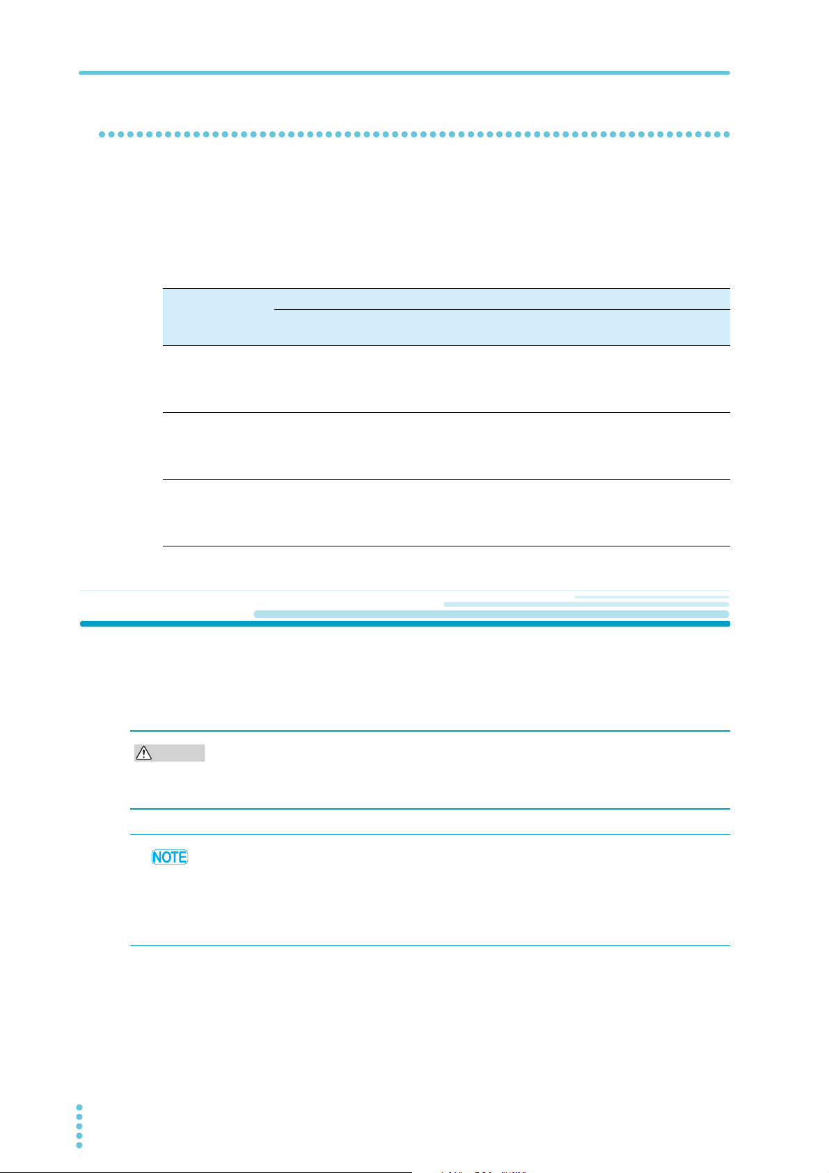
As shown in the following table, the initial settings of the PBZ-SR are different from the factory
default settings of individual PBZ power supplies. If you initialize the PBZ-SR to its factory
default settings, the factory default settings of individual PBZ power supplies will be applied,
so be sure to change the items in the following table.
For the factory default settings, see “List of Factory Default Settings” in the PBZ series User’s
Manual. For information on how to change the settings, see “Setting and Viewing Config
Settings” in the PBZ series User’s Manual.
Initial settings for the PBZ-SR series
Model
The number of parallel operation units
(UNIT)
3ON
4ON
5ON
Remote sensing on/off
(SENSING)
Turning Off
Lower the POWER switch lever to turn the power off.
“POWER OFF” is shown on the display for a few seconds and disappears.
After you turn the POWER switch off, wait at least 5 seconds after the fan stops before you
turn the POWER switch back on. Turning the PBZ-SR on too soon after you turn it off can
cause damage to the inrush current limiter circuit, as well as reduce the life of components
such as the POWER switch and the internal input fuses.
• The PBZ-SR series stores the panel settings (excluding output on/off condition)
immediately before the POWER switch is turned off. If you turn the power on, the PBZ-SR
starts in the same state as it was in the last time that it was turned off. If the POWER switch
is turned off immediately after changing the settings, the last settings may not be stored.
• If you want to turn off the POWER switches of the individual PBZ power supplies before the
POWER switch of the PBZ-SR, turn off the slave units first.
10 PBZ-SR
Page 11
2
WARNING
See
Connecting the Load
This chapter describes how to connect a load to the PBZ-SR.
Connecting the Load Cable
Selecting the Load Cable
To prevent the possibility of fire.
• Use a load cable with sufficient current capacity with respect to the rated output
current of the PBZ-SR series.
Possible electric shock.
• Use load cables whose rated voltage meets or exceeds the PBZ-SR’s isolation
voltage (500 Vdc).
p. 3
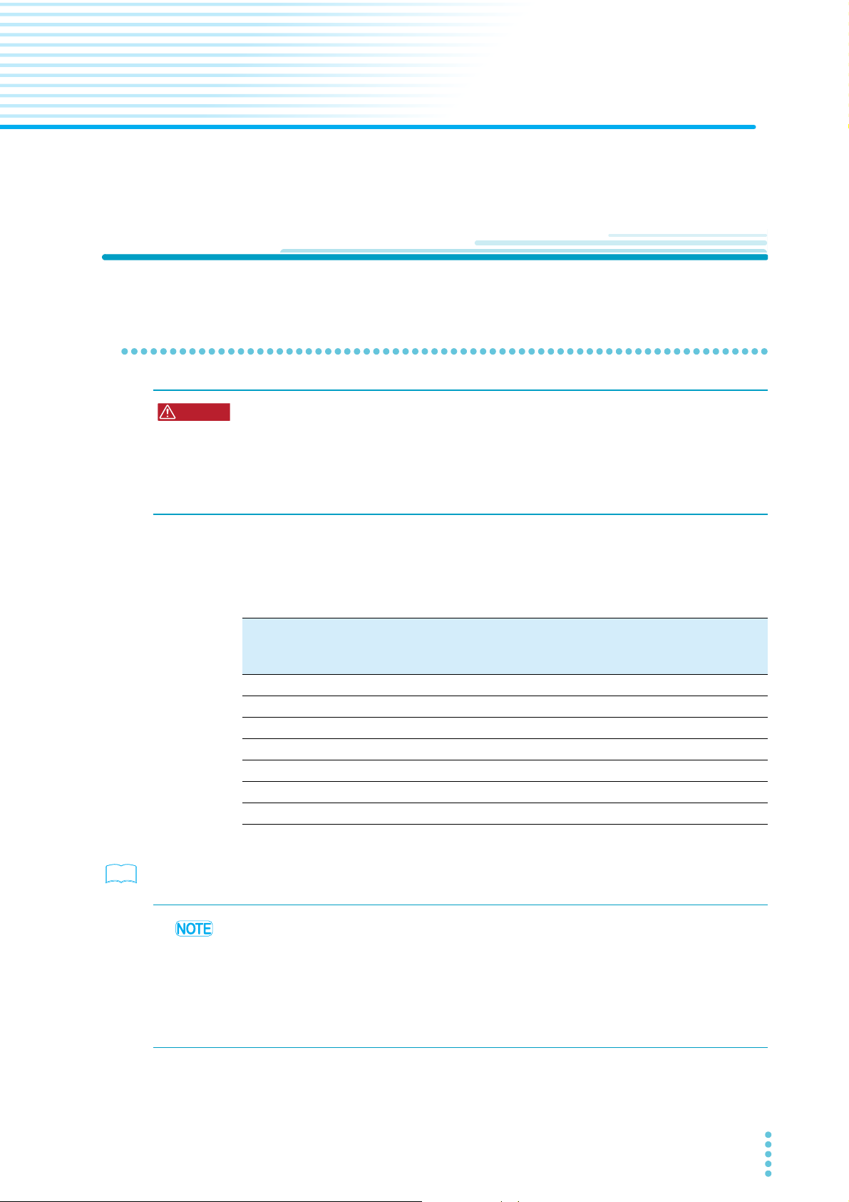
The load cables that you use must have a current capacity that allows the PBZ-SR’s rated
output current to flow. If you use load cables whose capacity meets or exceeds the rated
output current, even if the load is shorted, the cables will not be damaged. Use wires that
have diameters that correspond to the output current to connect to the load.
Nominal crosssections area
2
)
(mm
3.5 12 (3.31) 37 -
5.5 10 (5.26) 49 20
8 8 (8.37) 61 30
14 6 (13.3) 88 50
22 4 (21.15) 115 80
30 2 (33.62) 139 -
38 1 (42.41) 162 100
*1. Excerpt from Japanese laws related to electrical equipment.
You can also use the optional low inductance cable (TL02-PLZ, TL03-PLZ, LIC40-2P1MM6M6 or LIC40-2P2M-M6M6).
A cable’s temperature is determined by the resistive loss based on the current, the ambient
temperature, and the cable’s external thermal resistance. The above table shows the current
capacity of heat-resistant vinyl cables that have a maximum allowable temperature of 60 °C
when one of the cables is separated and stretched out horizontally in air in an ambient
temperature of 30 °C. The current capacity must be reduced under certain conditions, such
as when vinyl cables that have a low heat resistance are used, when the ambient
temperature is 30 °C or greater, or when cables are bundled together and little heat is
radiated.
AWG (reference
cross-section area;
2
)
mm
Allowable current
(A; Ta = 30 °C)
*1
Kikusui-recommended
current (A)
PBZ-SR 11
Page 12
Connecting the Load Cable
WARNING
CAUTION
Screw (M4)
Output terminal cover
Bolt (M8)
OUT
When using bolts
(PBZ20-100 SR example)
When using screws
(PBZ80-25 SR example)
Output
terminals
Crimping
terminals
Short bar
COM
Load Cable
Screw (M6)
See
See
Connecting the Load Cable
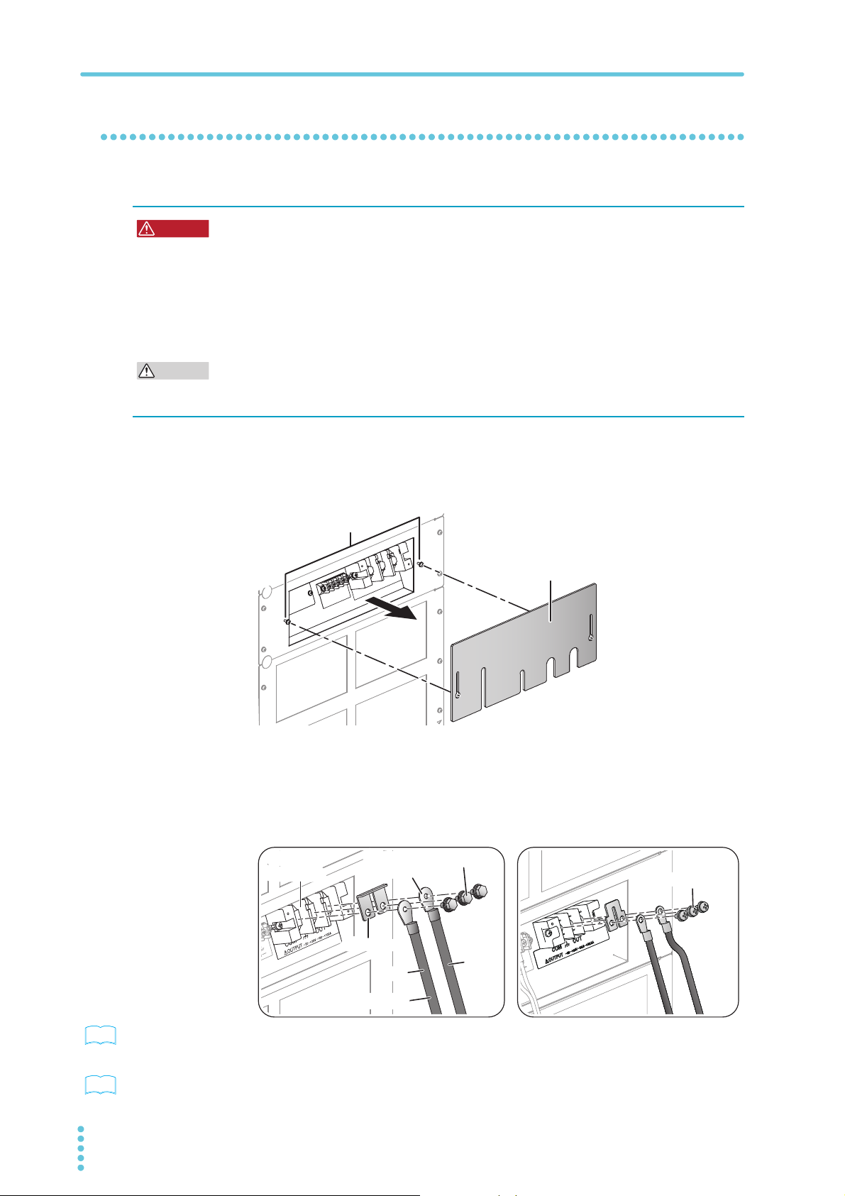
Using load cables, connect the load to the PBZ-SR through the output terminals on the rear
panel.
Possible electric shock.
• Turn the POWER switch off before you touch the OUTPUT terminals.
• Be sure to attach the OUTPUT terminal cover after you connect the load cables to
the OUTPUT terminals.
Risk of burns.
• The rear panel may become hot. Before you touch the rear panel, turn the POWER
switch off, and allow a sufficient amount of time for the rear panel to become cool.
Risk of overheating.
• Attach crimping terminal to the wire and use the set of screws that came with the package
for connection.
Lower the POWER switch lever of the PBZ-SR to turn the power off.
1
On the rear panel, loosen the screws holding the output terminal cover
2
in place, and remove the cover.
PBZ20-100 SR example
Connect the load cables to the OUTPUT terminals.
3
The size of the bolts used in the output terminal block is M8. Attach appropriate
crimping terminals to the load cable.
12 PBZ-SR
p. 3
p. 15
If want to use the optional low inductance cable (TL02-PLZ, TL03-PLZ, LIC40-2P1MM6M6 or LIC40-2P2M-M6M6), be sure to connect the cable to ground using the short
bar, as shown in the figure above.
To connect sensing cables, see “Using Remote Sensing.”
Page 13
Connecting the Load Cable
Load
OUTPUT
Chassis
terminal
OUT
COM
PBZ-SR
L
I
'I/'T
E = L × ('I/'T)
E: The induced voltage
E
L: The wiring inductance
'I: The change in current
'T: The duration of time over
which the current changes
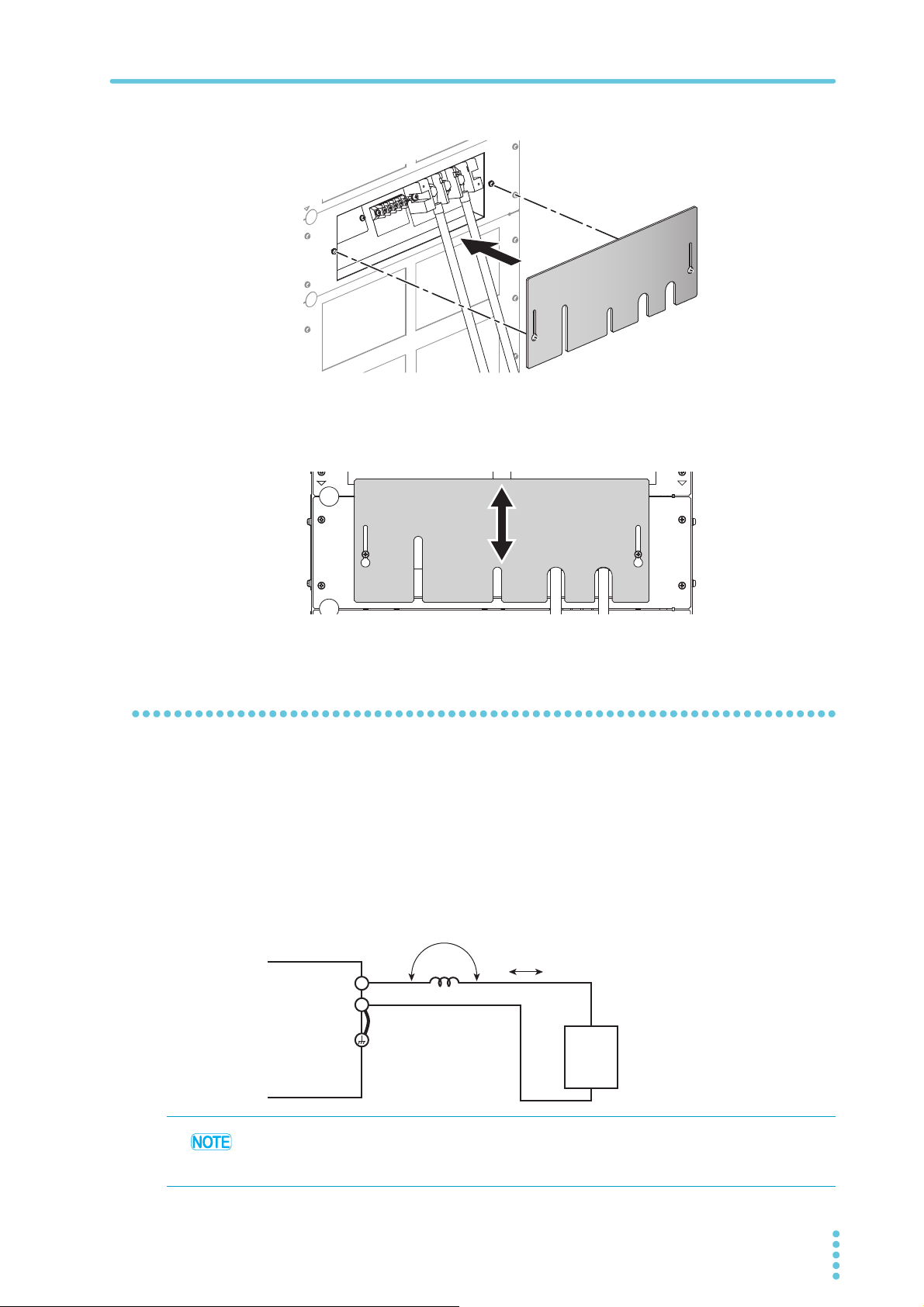
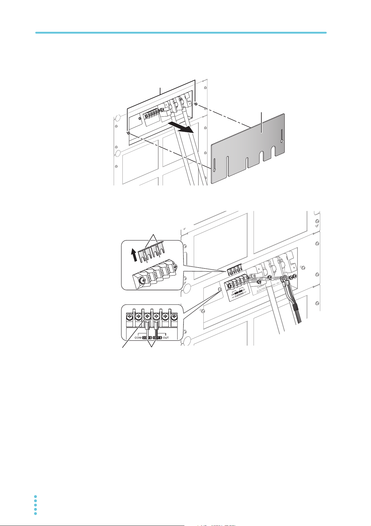
Attach the output terminal cover.
4
PBZ20-100 SR example
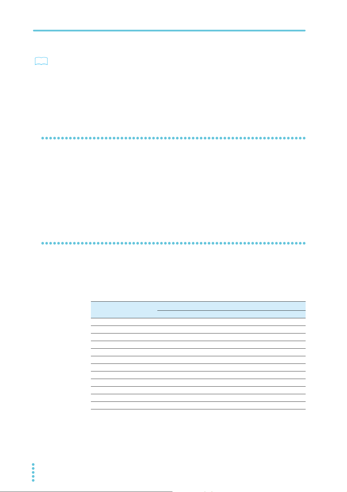
Adjust the output terminal cover to the appropriate position, and tighten
5
the screws.
Adjust the position so that the space between the cover and cables is small.
Influence of Cables
When you use the PBZ-SR, you must wire the load and configure the response setting
correctly and reduce the inductance. If these conditions are not met, the PBZ-SR may
oscillate or become unstable.
Load cables and inductance
Load cables have inductance L. If current I changes quickly, a large voltage is induced on
both ends of the cable. This voltage is applied to both the PBZ-SR and the load. The load
cable’s inductance L and voltage E that is induced according to the changes in current I
(hereafter referred to as the induced voltage) are expressed as follows:
PBZ-SR 13
Generally, a cable’s inductance is 1 μH per meter of cable. If 2 meters of cable are used to
wire the load (the total length of the cables that are connected to the OUT terminal and the
COM terminal) and the current change is 10 A/μs, the induced voltage is 20 V.
Page 14
Connecting the Load Cable
See
How to reduce the effect of wiring
p. 3
• You can reduce the inductance of load cables by using the optional low inductance
cables (TL02-PLZ, TL03-PLZ, LIC40-2P1M-M6M6 or LIC40-2P2M-M6M6).
• If fast transient response is not required, increase the response setting.
The value of I/T is reduced, so even if you can’t reduce the load cable’s inductance,
you can reduce the induced voltage. For details on the response setting, see “Response
Setting” in PBZ series User’s Manual.
• Use the shortest cables possible to wire the load, and twist them.
When Connecting Capacitive or Inductive Loads
Oscillation may occur when the PBZ-SR is connected to a capacitive load in CV mode or
when the PBZ-SR is connected to an inductive load in CC mode. To remedy this problem,
increase the response setting or use the soft start and soft stop features.
For details on each feature, see the following sections in the PBZ series User’s Manual.
• For CV mode and CC mode, see “CV/CC Mode.”
• For response settings, see “Response Setting.”
• For soft start and soft stop, see “The Output Soft Start and Soft Stop Features.”
When Connecting Battery Loads
If you connect a device to the OUTPUT terminals that can supply power, like a battery, the
PBZ-SR is a load to the device. In this situation, there is a limit to the amount of power that
the PBZ-SR can consume. When the PBZ-SR’s sink power becomes too large, it limits its
output current (the sink current to the PBZ-SR) so that the sink power reduces to a constant
value.
Model name
PBZ20-60 300 W 1200 W
PBZ20-80 400 W 1 600 W
PBZ20-100 500 W 2000 W
PBZ40-30 540 W 1200 W
PBZ40-40 720 W 1600 W
PBZ40-50 900 W 2000 W
PBZ60-20.1 600 W 1206 W
PBZ60-26.8 800 W 1608 W
PBZ60-33.5 1000 W 2010 W
PBZ80-15 600 W 1200 W
PBZ80-20 800 W 1600 W
PBZ80-25 1000 W 2000 W
*1. The sink power values are typical values at an ambient temperature of 23 °C.
Sink power
Bipolar mode Unipolar mode
*1
14 PBZ-SR
Page 15
Using Remote Sensing
WARNING
WARNING
CAUTION
Remote sensing is a feature that is used to switch the voltage measurement point of CV/CC
mode and the voltage feedback point of CV mode.
When remote sensing is enabled, the voltage measurement point of CV/CC mode and the
voltage feedback point of CV mode are switched from the rear panel OUTPUT terminals to
the contact points of the sensing terminals. Connecting the sensing terminals to the load (1)
reduces the influence of the voltage drop caused by the resistive component of the load wires
and by the load current and (2) allows measurement and compensation of the output voltage
across the load. The compensation of the output voltage is effective to the voltage drop that is
1.8 V or less for a single line.
Remote sensing of CV mode has a protection feature. Even if the remote sensing wires are
connected in reverse, shorted, or disconnected, the output voltage in CV mode is limited
within the specified voltage ± approximately 3.6 V. When the connection is fixed, the
protection feature automatically recovers.
To avoid electric shock and damage to the PBZ-SR’s internal circuits, observe the
following precautions.
• Never wire the sensing terminals while the POWER switch is turned on.
• For sensing cables, use cables whose rated voltage is higher than the PBZ-SR’s
isolation voltage (500 Vdc).
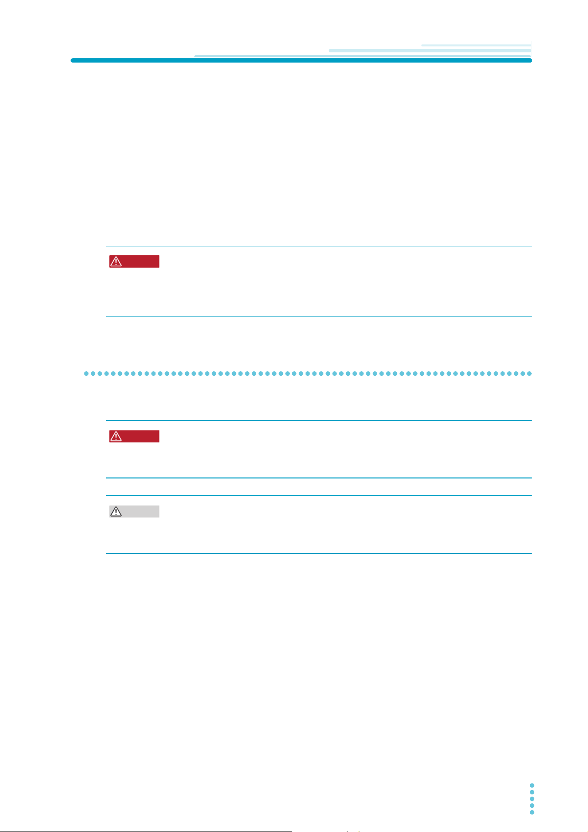
Connecting the Sensing Cables
To use remote sensing, connect sensing cables to the sensing terminals of the PBZ-SR.
Risk of burns.
• The rear panel may become hot during operation. Before you touch the rear panel,
turn the POWER switch off, and allow a sufficient amount of time for the rear panel
to become cool.
• If the remote sensing cables come loose while remote sensing is in use, the PBZ-SR and
load may break. Be sure to connect the cables securely.
• If you are not using remote sensing, be sure to attach the two short bars to the sensing
terminals.
PBZ-SR 15
Page 16
Using Remote Sensing
Screw (M4)
Output terminal cover
Sensing cables
Connect the sensing cables.
Screw (M4)
Use AWG24 to AWG16 (0.2 mm2 to 1.25 mm2) cables.
To avoid noise induction, use a two-wire shielded cable to connect the sensing
terminals. Connect the shield to the OUTPUT COM terminal. If you cannot use a
shielded cable, twist the sensing cables from the OUT terminal and the COM
terminal together.
Short bars
Remove the short bars that are
attached to the sensing terminals.
Lower the POWER switch lever of the PBZ-SR to turn the power off.
1
On the rear panel, loosen the screws holding the output terminal cover
2
in place, and remove the cover.
Connect the sensing cables to the sensing terminals.
3
Remove the two short bars from the sensing terminals before connecting the cables.
short bars must be connected to the sensing terminals when remote sensing is not in
use. Store the short bars in a safe place.
16 PBZ-SR
Page 17
Using Remote Sensing
Two-wire shielded cable
Load
OUTPUT
Chassis
tarminal
SENSING
OUT
COM
OUT
COM
Shield
Attach the OUTPUT terminal cover.
4
Adjust the output terminal cover to the appropriate position, and tighten
5
the screws.
Adjust the position so that the space between the cover and cables is small.
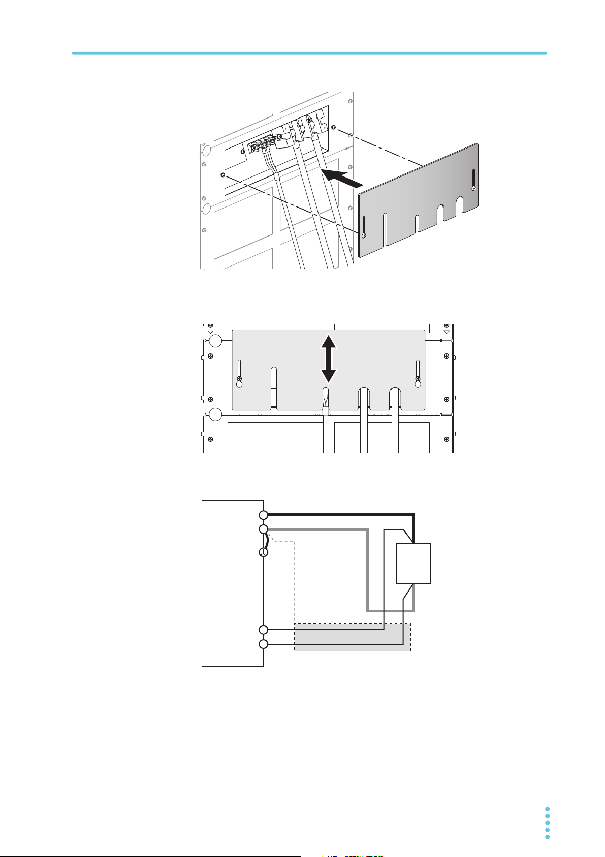
Connect the sensing cables to the load.
6
Connect by referring to the following information.
When remote sensing is enabled, if the sensing terminals are shorted, opened, or are
wired in reverse, the sensing protection is activated, and the output voltage in CV
mode is limited within the specified voltage ± approximately 3.6 V. When the
connection is fixed, the protection feature automatically recovers. Do not leave the
PBZ-SR while the sensing protection is activated.
PBZ-SR 17
Page 18
Using Remote Sensing
Load
OUTPUT
Chassis
terminal
SENSING
OUT
COM
OUT
COM
Switch
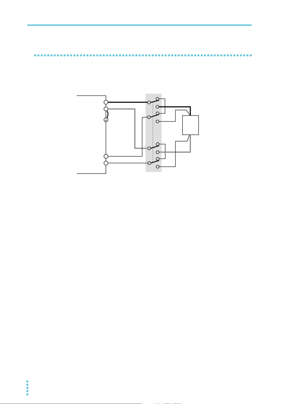
If You Are Inserting a Mechanical Switch between the OUTPUT Terminals and the Load
If you want to insert a mechanical switch between the OUTPUT terminals and the load, be
sure to include the sensing cables in the switch as shown in the figure below and turn on and
off the load and sensing cables simultaneously. Before you turn the mechanical switch on or
off, be sure to turn the output or the POWER switch off.
18 PBZ-SR
Page 19
Connecting External Devices
WARNING
Screw (M4)
J1 connector
3
This chapter describes how to connect an external controller when you want to control the
PBZ-SR externally or remotely.
Connecting an External Controller
By applying control signals to the rear panel J1 connector, you can control the following
aspects of the PBZ-SR. The J1 connector also generates status signals that indicate the
PBZ-SR’s operating state.
• Controlling DC signals (the DC settings)
• Turning the OUTPUT terminal’s output on and off
• Shutting down the PBZ-SR
For details on external control and how to perform it, see “External Control” in the PBZ series
User’s Manual.
.
Possible electric shock.
• Before removing the rear panel or connecting to the J1 connector, be sure to lower
the POWER switch lever of the PBZ-SR to turn the power off.
Risk of burns.
• The rear panel may become hot during operation. Before you touch the rear panel,
turn the POWER switch off, and allow a sufficient amount of time for the rear panel
to become cool.
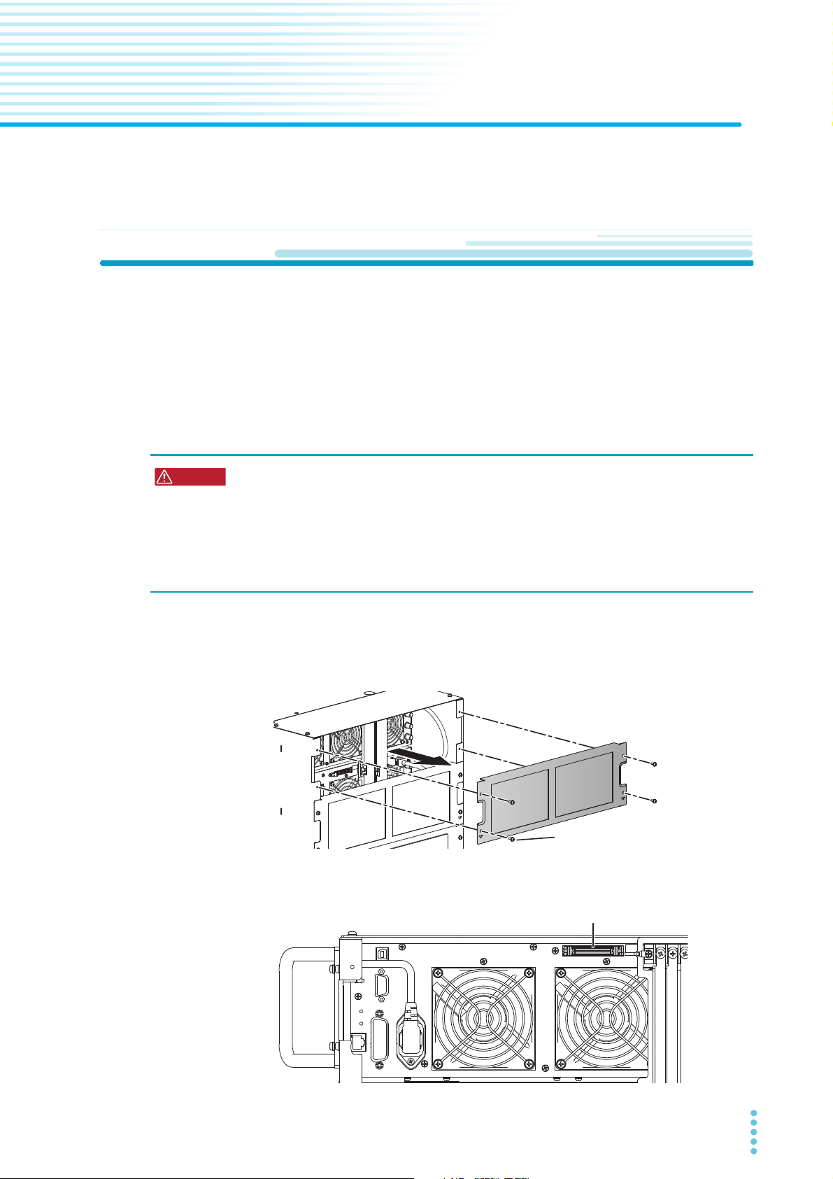
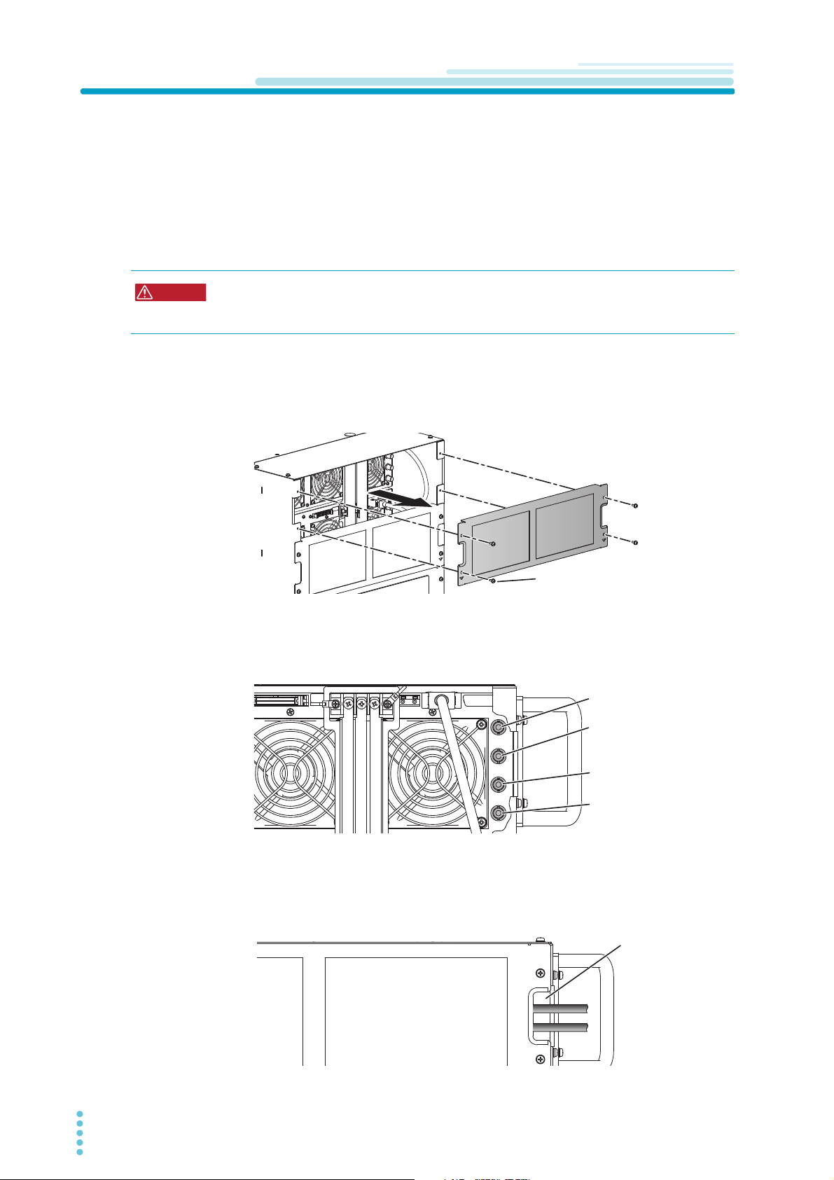
Lower the POWER switch lever of the PBZ-SR to turn the power off.
1
Remove the topmost rear panel.
2
You can now see the master unit rear panel.
Remove the dummy plug that is attached to the J1 connector of the
3
master unit.
PBZ-SR 19
Page 20
Connecting an External Controller
Wiring opening
(the opening on
the left edge of
the rear panel)
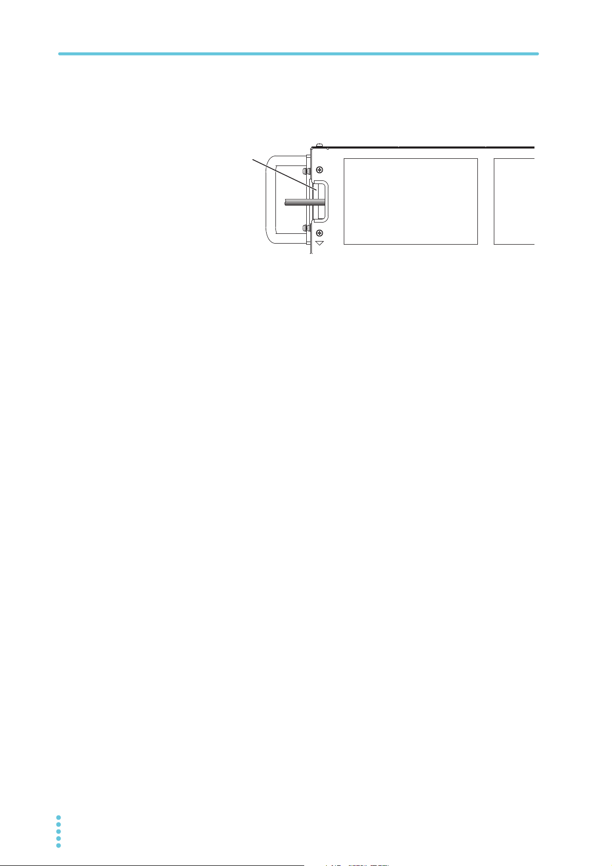
Connect a cable to the J1 connector of the master unit.
4
Attach the rear panel that you removed in step 2 .
5
When you attach the rear panel, pass the cables that you wired to the J1 connector
through the open space on the left edge of the panel.
20 PBZ-SR
Page 21
Connecting an Remote Controller
WARNING
Screw (M4)
GPIB
connector
LAN
connector
RS232C
connector
USB
connector
Wiring opening
(the opening on
the left edge of
the rear panel)
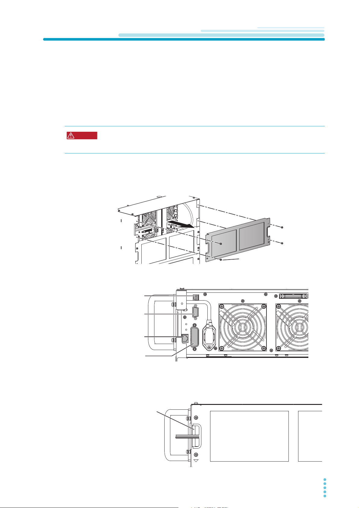
In addition to controlling the PBZ-SR from the front panel, you can control it remotely through
the following standard-equipped interfaces.
• RS232C interface
• GPIB interface
• USB interface
• LAN interface
You cannot control the PBZ-SR through RS232C, GPIB, USB, and LAN at the same time.
For details on remote control and how to perform it, see the PBZ Series Communication
Interface Manual.
Risk of electric shock. Before removing the rear panel or connecting to the interface
connector, be sure to lower the POWER switch lever of the PBZ-SR to turn the power
off.
Lower the POWER switch lever of the PBZ-SR to turn the power off.
1
Remove the topmost rear panel.
2
You can now see the master unit rear panel.
Connect a cable to the master unit's interface connector that you are
3
going to use.
.
Attach the rear panel that you removed in step 2 .
4
When you attach the rear panel, pass the cable that you connected to the interface
connector through the open space on the left edge of the panel.
.
PBZ-SR 21
Page 22
Connecting Devices to Synchronize
WARNING
Screw (M4)
TRIG IN terminal
10MHz OUT terminal
10MHz IN terminal
TRIG OUT terminal
Wiring opening
(the opening on
the right edge of
the rear panel)
You can use the following synchronization features by connecting multiple products
(individual PBZ power supplies or other PBZ-SR series) to the PBZ-SR.
• Turn the output of multiple units on and off at the same time.
• Synchronize sequence start timing across multiple units.
• Synchronize the clocks of multiple PBZ-SRs.
Output on/off synchronization and sequence start timing synchronization can be used at the
same time as clock synchronization. For details on the synchronization feature and how to
use it, see “Synchronization Feature” in the PBZ series User’s Manual.
Risk of electric shock. Before removing the rear panel or connecting to the interface
connector, be sure to lower the POWER switch lever of the PBZ-SR to turn the power
off.
Lower the POWER switch lever of the PBZ-SR to turn the power off.
1
Remove the topmost rear panel.
2
You can now see the master unit rear panel.
Connect a cable to the 10MHz or TRIG terminal of the master unit.
3
To perform output on/off synchronization and sequence start timing synchronization,
use the TRIG terminal.
To perform clock synchronization, use the 10MHz terminal.
Attach the rear panel that you removed in step 2 .
4
When you attach the rear panel, pass the cable that you connected to the interface
connector through the open space on the right edge of the panel.
.
22 PBZ-SR
Page 23
Connecting an External Signal Source
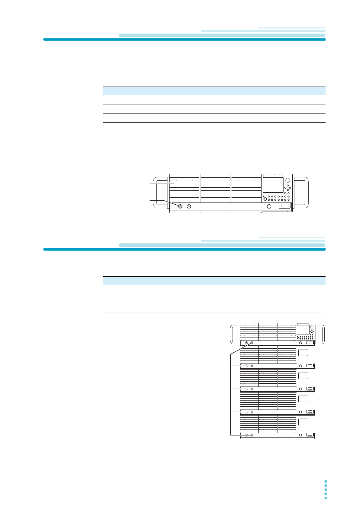
EXT SIG IN
terminal
Master unit
I MON
terminal
Example of PBZ20-100 SR
By using an external signal, you can create a bipolar amplifier that amplifies the input signal
that the PBZ-SR receives through EXT SIG IN (BNC terminal). You can set the gain, the
polarity (inverted or not inverted), and the offset of the amplifier. For details on how to use an
external signal source, see “Using the EXT SIG IN Signal (External Signal Source)” in the
PBZ series User’s Manual.
Item Input terminal specifications
Maximum allowable input voltage ±12 Vpeak
Input impedance Approx. 10 kΩ
Common terminal Connected to the OUTPUT COM terminal
Lower the POWER switch lever of the PBZ-SR to turn the power off.
1
Connect an external signal source to the EXT SIG IN terminal on the
2
front panel of the master unit.
Do not connect to the EXT SIG IN terminals of the slave units.
Using Current Monitor Output
The front panel I MON terminal (BNC terminal) generates a voltage that is proportional to the
output current.
Item I MON terminal specifications
Output voltage ± 2 V at the rated current
Frequency response DC to 20 kHz (-3 dB)
Common terminal Connected to the OUTPUT COM terminal
On the master unit, voltage output
proportional to the total output current
(total parallel current) of the PBZ-SR is
generated. On the slave units, voltage
output proportional to the output current
per slave unit is generated.
PBZ-SR 23
Page 24
Trademarks
10
环境保护使用期限
Environment-friendly Use Period
All company names and product names used in this manual are trademarks or registered trademarks of
their respective companies.
Copyrights
The contents of this manual may not be reproduced, in whole or in part, without the prior consent of the
copyright holder. The specifications of this product and the contents of this manual are subject to change
without prior notice.
© 2013
该标记为适用于在中华人民共和国销售的电子信息产品的环境保护使用期限。
只要遵守有关该产品的安全及使用注意事项,从制造年月起计算,在该年度内,就不会对环境污染、人身、财产产生重
大的影响。
产品的废弃请遵守有关规定。
产品的制造年月可以在以下网址中确认。
http://www.kikusui.co.jp/pi/
有毒有害物质或元素名称及含有標示
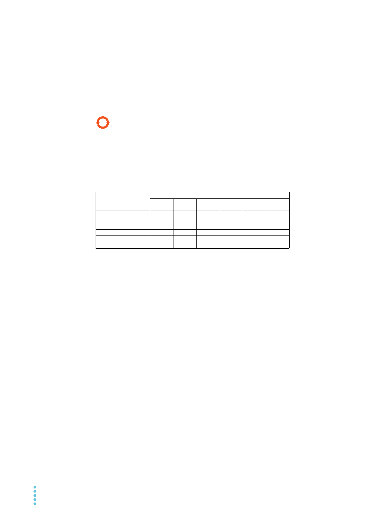
Name of hazardous materials and symbol of element in the equipment and quantity
部件名称
印刷电路板组装品
显示器
内部接线
外壳
底盘组装品 (含变压器)
辅助设备
铅
Pb
Hg
汞
有毒有害物质或元素
Cd
镉
六价铬
Cr(VI)
多溴联苯
PBB
多溴二苯醚
PBDE
本表格依据 SJ/T 11364 的规定编制。
:
该部件所有均质材料的有毒有害物质的含量不超过 GB/T 26572 标准所规定的极限值要求。
:
该部件至少有一种均质材料的有毒有害物质的含量超过 GB/T 26572 标准所规定的极限值要求。
24 PBZ-SR
 Loading...