

Page 1
Internet
/
http://www.kikusui.co.jp
Harmonic / Flicker Analyzer
Harmonic/Flicker Analyzer
MODEL KHA3000
Supports harmonic and fl icker compliance testing of single-phase and three-phase equipment
IEC61000-3-2 Ed3.0(Harmonics for 16A or less)
IEC61000-3-3 Ed1.2 (Flicker for 16A or less)
IEC61000-3-11 (Flicker for over 16A)
IEC61000-3-12 (Harmonics for 75A or less)
IEC61000-4-7 Ed2/Ed1 (Interharmonics ON/OFF)
Page 2
Harmonic /Flicker Analyzer
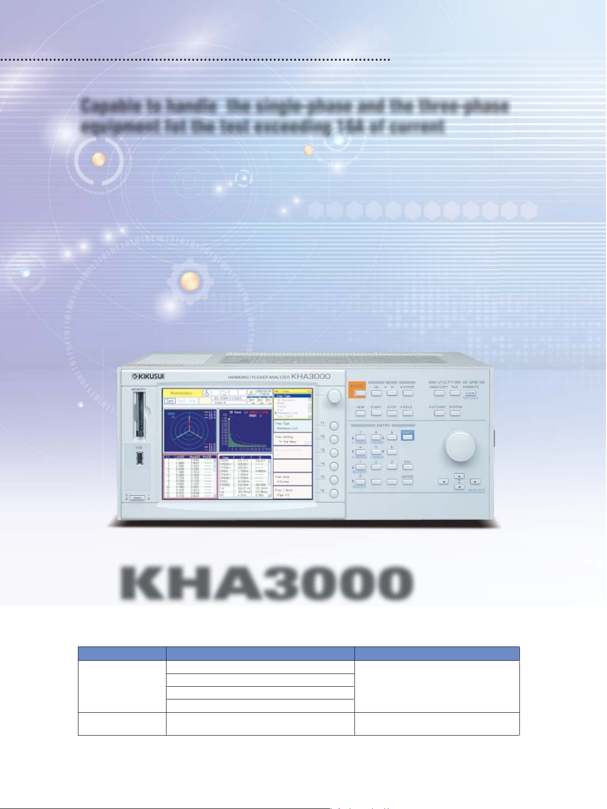
Capable to handle the single-phase and the three-phase
equipment for the test exceeding 16A of current
KHA3000, in addition to the complied standards and features of the KHA1000 (dedicated for single phase),
is equipped for the harmonic and fl icker compliance test exceeding 16A of the single-phase and the
three-phase equipment. With this unit alone, you can take highly accurate simultaneous three-phase
measurements up to 40A/phase*. Furthermore, the KHA series is compliant with two measurement
technique standards, the existing and the latest versions, so you can simply select to take measurements
for the latest standard including interharmonics and for the conventional integral multiple harmonics without
using any other device. In addition to the real-time display that can be used like an oscilloscope and FFT
analyzer, the unit offers the real-time judgment of compliance with standards. Using this unit alone, you
can judge test results and prepare result reports without the use of a PC. On top of that, you can easily set
up a standard compliance test system by combining KHA3000 with an AC power supply (PCR-LA Series)
and a line impedance network (LIN40MA-PCR-L).
*Support for measurement beyond 40A/phase is scheduled with an external current sensor (option) and an update of the
fi rmware.
Harmonic/Flicker Analyzer
KHA3000
[
Complied standards
Category Limit value standard Edition Measurement technique standard Edition
Harmonic current
Flicker/voltage fl uctuation
Note: The Chinese Standard GB17625.1-2003 conforms to IEC61000-3-2:2001, thus, tests can be carried out using this unit by specifying the nominal
voltage (220V/380V) for IEC61000-3-2 Ed2.2.
2
]
Compliance with the following standards can be tested.
IEC61000-3-2Ed3 [EN61000-3-2:2006
IEC61000-3-2Ed2.2 [EN61000-3-2A2:2005
JIS C61000-3-2:2005
IEC61000-3-12
IEC61000-3-3Ed1.2 [EN61000-3-3A2:2005
IEC61000-3-11
Initial version
Initial version
[EN61000-3-12:2005
[EN61000-3-11:2000
]
]
IEC61000-4-7
]
]
]
[EN61000-4-15A1:2003
IEC61000-4-7Ed2
[EN61000-4-7:2002
[EN61000-4-7:1993
IEC61000-4-15Ed1.1
Initial version
]
]
]
Page 3
Characteristics and Features
supply/reference impedance
s
C
card
Finishing the test
Applied to the single phase and the three-phases (40A/phase)
◆
16A/phase or less
IEC61000-3-2, -3-3 IEC61000-3-12, -3-11
Single
phase
3 phases
*1: The JIS specifi es 20A/ phase or less.
*2: For measurement of 40A or more phase current, an optional device (external
current sensor) is required.
*3: KHA1000 is dedicated for single phase (16A or less).
Installed with the latest standards of both
◆
KHA1000
*1
*3
KHA3000
Coversall.
16A to 75A/phase
harmonic and fl icker limits
Refer to the table
bottom of left page.
*The latest standard is referred to the DOP(Date of issue)of the
EN standard.
Comply with the old and new versions of harmonic
◆
[Complied standards]
specified on the
measuring instrument standards IEC61000-4-7
To select the standard, your desired combination can be arranged
by choosing from the limit value standarad and the testing
measurement standard.
*2
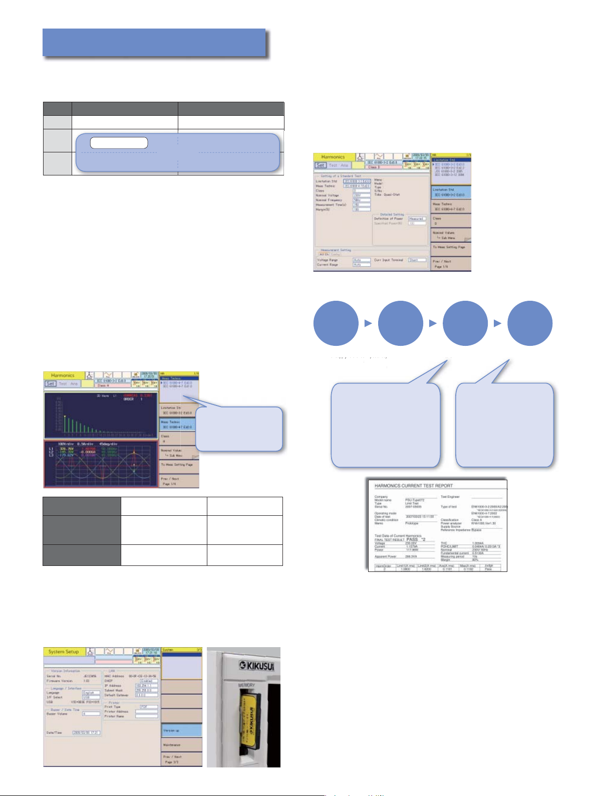
No need for a PC for compliance testing
◆
Using this device alone, you can perform a series of test
processes - from setting test conditions and running the test to
judging the test results and outputting result reports - without
the use of a PC. You can enter comments from the test condition
setting screen.
●
Operation fl ow using KHA3000 - from test condition setting to report printing
Test
preparations
• Setting the test system
(
AC power supply/reference impedance
• Setting test conditions
test condition
•
Selecting the measurement screen
ng the measurement screen
Start of test Test resultTest analysis
)
• Saving test data in
a CF card
a
• Printing test reports
• Finishing the test
You can switch between
the old and new
standards to view the
differences in real time.
Harmonic measuring
instrument standard
Window width
Interharmonics
Easy upgrade when standards are modifi ed
◆
IEC61000-4-7Ed2 IEC61000-4-7Ed1
200ms
10c ycle /5 0Hz
12cycle /60 Hz
Interharmonics grouping
(unit of 5 Hz)
16c ycle
None
Integer order harmonics only
(supports the latest standards)
The unit can be easily upgraded from the front panel using a CF
card.
*Users are requested to prepare CF cards.
*Support for USB memory is currently under development.
Link to a PC with a CF card
(external memory)
A Compact Flash (CF) memory
card is used to save test
conditions, reports, screen
hardcopies and data.
*Support for USB memory is
currently under development.
Example of test report (harmonic compliance test)
▲
Test reports can be output
to a CF card in either the
PDF or text format.
You can easily view and
print them using a PC.
The text format is useful
when you want to prepare a
report in your own format.
3
Page 4
Measurement for harmonic compliance test (16A to 75A/phase)
Is it balanced equipment?
YES
NO
YES
NO
NO
NO
YES
YES YES
NO
Is it hybrid equipment?
Is the maximum 3rd harmonic current
less than 5% of fundamental current?
Is condition a), b) or c) met?
Apply th e limit valu e table
(Standard table 4)
Apply th e limit valu e table
(Standard table 3)
For each p art of hybri d equipm ent,
apply the applicable table,
Apply th e limit valu e table
(Sta ndard ta ble 2, 3 or 4 .)
Limit val ues of “Ba lanced 3 -phase
equipment of specified conditions”
Limit values of
“Balanced three-phase equipment”
Limit values of “equipment other than
balanced three-phase equipment”
Is it a bala nced int erphas e part or a 3 -phase
part separate from the single phase?
Apply th e limit valu e table
(Standard table 2)
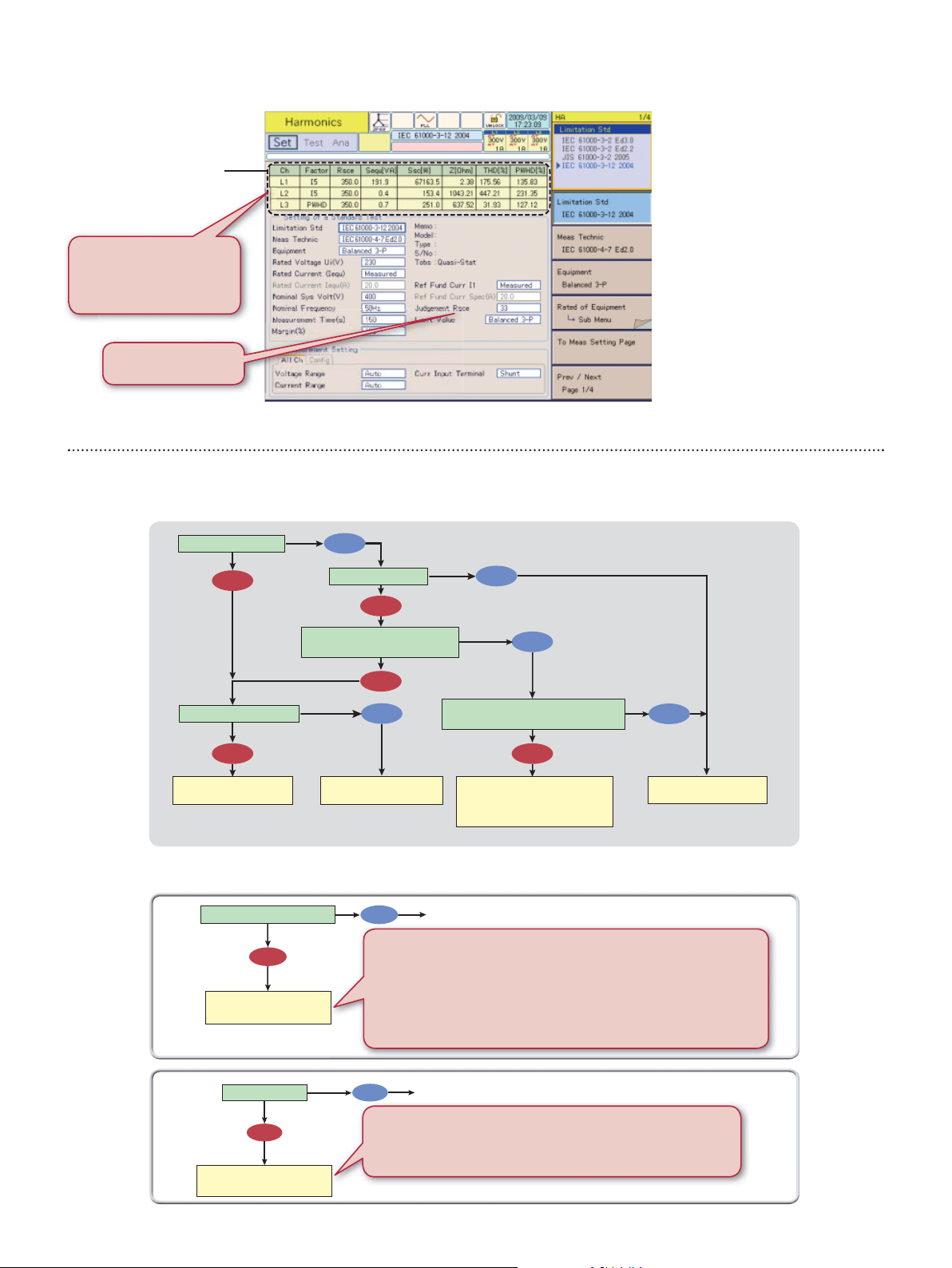
◆
IEC/EN61000-3-12
●
Measured values
You can check the minimum
Rsce values that clear the limit
values on the real-time monitor.
Set an estimated shortcircuit ratio(Rsce) value
[Reference] The test fl ow of IEC61000-3-12 limit value application procedure
You can set test conditions while
■
monitoring the measured values.
For the equipment not applied
within R (33), the minimum
short-circuit ratio (Rsce) value
that clears the limit values up to
R (350) needs to be calculated.
KHA3000 can automatically
calculate the short-circuit ratio
(Rsce) values from its the
short-circuit ratio (Rsce)
measured values, I
I
, THD and PWHD, and display
13
, I5, I7, I9, I11,
3
in real time the minimum
short-circuit ratio (Rsce) value of
each harmonic order.
4
Select a category of the equipment for IEC61000-3-12 (single phase, line, balanced three-phase and
unbalanced three-phase) and follow the fl owchart. You can select limit values for the category.
Is it balanced 3-phase equipment?
YES
Does it meet any of the specified
conditions a), b) and c)?
Is it hybrid equipment?
YES
Is the maximum 3rd harmonic current
less than 5% of fundamental current?
NO
You can measure the phase angle of the 5th harmonic current.
You can chec k the specifi ed cond itions.
Specifi ed condition a): You can check for e ach phase whether or not the phase of
the 5th har monic current is w ithin the range of 90° and 150°.
Specifi ed condition c): You can c heck for each phase whether or not the 5th and
7th harmonic current values are both within 5% of t he fundamental c urrent.
*Specifi ed condition b) is d etermin ed by the de sign engineer of ma nufacturers.
NO
You can check whether or not the 3rd harmonic current is less
than 5% of the fundamental current.
In addition, you can selec t a measured value or specifi ed value for the
fundamental current an d view it in either % or Arms.
Page 5
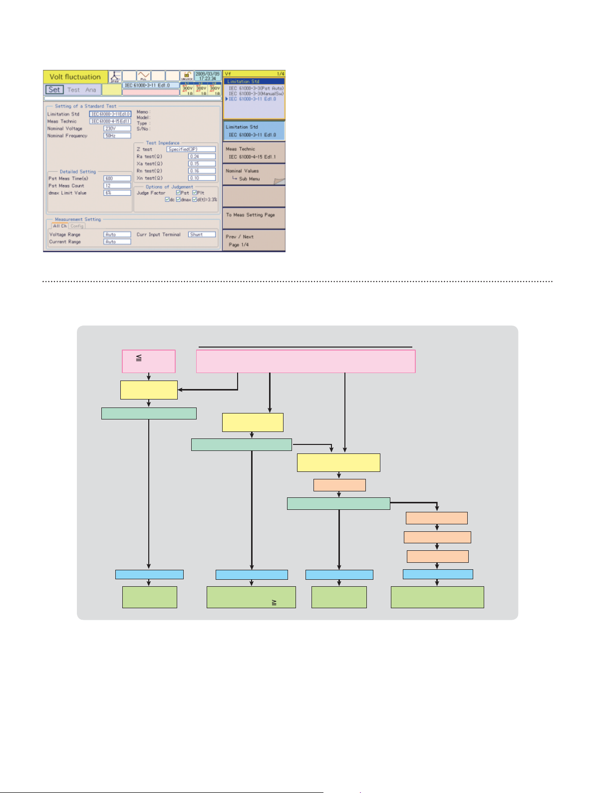
Measurement for fl icker compliance (voltagee fl uctuation) test (16A to 75A/phase)
◆
IEC/EN61000-3-11
●
You can enter the default Ztest prescribed in IEC61000-3-11.
■
It can be used when you declare the current of the connecting
power supply is 100A or more per phase or when declaring the
maximum allowed system impedance (Zmax).
Judgment of limit values is not required for some items depending
■
on the equipment. For this reason, KHA3000 is designed to let
you select desired items.
[Reference] Outline of IEC61000-3-11 test
All types of equipment with rated current of 75A or less
16A
3-3 standard
Test with Zref
Zrefで試験
0.4+j0.25(7)
3-3 limit values are cleared.
Pass
Fail
Test with Ztest
0.25+j0.25(7)
3-11 limit values are cleared.
Pass
> 16A
3-11 standard
Fail
Test with Ztest
random/conditioned
(7)
Convert to Zref.
3-11 limit values are cleared.
Fail
Pass
Calculate Zsys.
Determine Zmax.
Declare Zmax.
Compliant with 3-3 Compliant with 3-3
Connectable
to anywhere
You can specify test impedance.
◆
You can select the standard value (0.25Ω + j0.25Ω) or specifi ed values.
*You can enter specifi ed values for Z
In addition, you can enter specifi ed values for neutral line impedance Z
KHA3000 automatically calculates the measured values (dc, dmax, Pst and Plt) and makes a judgment
◆
whether or not they are below the limit values. When the converted values did not clear the limit values, the unit
automatically calculates the system impedance and displays the minimum value of the 4 Zsys values as Zmax.
This Zmax is declared for IEC61000-3-11.
In manual switching, KHA3000 can calculate Zsys1 and Zsys2 only and display the smaller of the two as Zmax.
(This is possible by switching the display items.)
When testing with randomly selected impedance, time measurement d (t) > 3.3% is not necessary. (You can
◆
remove it from judgment using the judgment option.)
Connectable to supply
current capacity of 100A
A
test and XA test (for reactance) in the range of 0.001Ω to 9.999Ω.
Zact ≤ Zmax
Connectable
to anywhere
N
and XN.
Compliant with 3-11Compliant with 3-11
Connectable to distribution
network of Zmax or less
5
Page 6

Real-time display & measurement that gives you a quick grasp of the EUT status
◆
●
List of view types
Harmonic current test Flicker/voltage fl uctuation test
●
●
●
Graph display
List display
●
●
●
●
●
●
●
V/I waveforms
2D harmonics
3D harmonics
THC
Current trend
Harmonic current trend
Vec tor phases
List (real-time measured values)
Harmonic list
Result list
●
rms waveform
●
St (shor t time fl icker value) waveform
●
CPF (cumulative prob abilit y) curve
●
dc waveform
●
dmax waveform
●
d (t) > 3.3% waveform
●
Flicker list
●
Result list
●
d measurement (manual switch)
V/I waveforms
▲
2D harmonics
▲
rms waveform
▲
dmax waveform
▲
Vectors
▲
Harmonic list
6
▲
Flicker list
▲
Result list
▲
Page 7

Allows changes in the test conditions while monitoring
◆
You can change the
test conditions with
the monitor screen
Capable of simultaneous measurement of the three-phases
◆
The long-time fl icker value in all segment time, “Plt” is specifi ed to be 2 hours for the fl icker monitoring period.
For three-phase equipment, measurement can be taken for each phase, but that will take 2 hours x 3 = 6 hours.
Simultaneous measurement of three-phases can shorten the measuring (testing) time to 2 hours.
VIEW key
unchanged.
AC power supply Impedance
In order to fully cover the EUT input methods, you can set the wiring method (single phase, single phase 3-wire, three-
◆
phase 3-wire and three-phase 4-wire). In addition, for the setting of L1, L2 and L3 (channels), you can select interlock or
independent. This allows appropriate measurement for equipment with largely different phase currents.
In order to support measurement of each channel for 3 phases, the voltage and current ranges were separated for each
◆
channel and AUTO range was established for each.
In addition, you can adjust the DC offset for each range with a single touch.
Supports “repeatability” check
◆
Comparison can be made
between the present
measurement data and
the past measurement
data to check whether or
not the error is within the
specifi ed allowable range.
This feature is helpful in
evaluating the
“repeatability” that is
required in harmonic
compliance testing.
U
network
V
W
N
G
SOURCE LOAD
KHA3000
L1
A
V
L2
A
L3
N
G
V
A
V
Equipped with a quality check function for the
◆
Equipment under test (EUT)
U
V
W
N
G
testing power supply
KHA3000 is equipped
with a function to
measure the voltage,
frequency, peak voltage
and distortion rate of the
AC power used for
harmonic compliance
testing in order to check
whether or not the power
supply is adequate for the
intended test.
The IEC requirements
The measurement repeatability shall be within ±5%.
IEC61000-3-12:
harmonic orders shall be within ±5%.
The repeatability of the harmonics beyond the 7th harmonic order shall
be within ±10% or ±1% of the reference fundamental current, whichever
is larger.
The repeatability of the fundamental and 7th and lower
The IEC requirements
IEC61000-3-2:
3rd (0.9%), 5th (0.4%), 7th (0.3%), 9th (0.2%), even harmonic order
between 2nd and 10th (0.2%), 11th to 40th (0.1%)
IEC61000-3-12:
5th (1.5%), 3rd and 7th (1.25%), 11th (0.7%), 9th and 13th (0.6%), even
harmonic orders between 2nd and 10th (0.4%), 12th and 14th to 40th (0.3%)
The voltage harmonics must be the following values or less.
Output voltage and harmonic inclusion rate under no load
7
Page 8

Providing all major basic measurements
◆
Rush current measurement
◆
KHA3000 is capable of
measuring all major basic
items including voltage,
current, power, power
factor, apparent power,
reactive power and
frequency.
It also provides other
measurement functions
such as waveform
monitoring and
measurements of rush
current and harmonic
current in low frequency
zones. These features
make KHA3000 a convenient routine work tool for development
and design processes.
The assist function provides guidance on
◆
standards and technical terms
KHA3000 is equipped
with the “Assist function”
that provides guidance
on the technical terms
used in the standards as
well as the equipment
class setting procedure.
This function can support
the users not familiar with
the standards to readily
get started with a test.
KHA3000 observes the
waveform of the rush
current exceeding the
trigger level. It can also
observe the voltage
waveform. It capable to
measure a rush current
up to 160A peak.
The measuring range
can be expanded to a
high current by using an
optional external current
sensor with updating the fi rmware.
A rush current can be measured while the EUT is connected. This saves
you from going through the trouble of preparing an oscilloscope and
current probe. Set the input phase angle of the AC power supply using
the application software (SD006-KHA), and turn on the unit. The rush
current can be measured with good reproducibility. The phase angle can
be set in the unit of 1°.
Generates test reports in both PDF and text formats
◆
Reports can be output to a
CF card in either PDF or text
format.
You can easily view and print
them using a PC.
The text format is useful to
convert into your own format.
User-friendly terminals and interfaces
◆
KHA3000 comes standard with GPIB, RS232C and USB.
SCPI commands make it possible to use the unit as a generalpurpose power analyzer by connecting it to your computer.
Easy connection
The terminals for power input and load output are separated. This arrangement
prevents connection errors, thereby eliminating the risk of short-circuiting.
Of course, voltage sensing at the load is supported as well.
KHA3000 offers both simplicity and expandability.
Example of regular connection
4
4
0
0
・Maximum of 40A can be measured.
Rear panel
▼
【
Voltage sensing
【
LOAD terminals】
【
MONITOR
Ⅰ
I → IHiLo
Ⅴ
Remote controller
】
SOURCE terminals
【
他
他
Reference impedance
back monitor terminal
[Voltage sensing wire]
Since current does not
flow,the wire equivalent to
UL1015 AWG20 is
sufficient. (Withstand
voltage is required.)
40
40
[Current sensing wire]
Select a wire that can
withstand 40A maximum.
2
2
1
1
(It affects a voltage drop.)
2
is recommended.
21 mm
GPIB
【
RS-232C
【
】
USB
【
】
】
】
】
・When replacing an other manufacturer’s power analyzer, connect as shown above. You can continue using the unit as before.
・ If the power value is negative, switch the polarity of either the voltage or current sensing wire to fix it.
8
Page 9

Specifi cations
Item Specifi cation
Maximum input voltage 600Vrms / 900Vpeak (CAT I),400Vrms (CAT II)
Common input specifi cations
Voltage measurement function
Current measurement function
Power measurement function
Frequency measurement
function
Phase measurement function
Harmonic current measurement
function
Harmonic voltage measurement
function (Measurement power
quality check function)
Flicker/voltage fl uctuation
analysis function
General measurement function Current/voltage waveform monitor, FFT analyzer and In-rush current measurement
Communication interface GPIB, RS232C, USB
Removal data storage Supported media Compact Flash memory card (CF card), maximum capacity: 512 MB
External equipment control
function
AC Input Nominal voltage range 100 to 240V AC50Hz to 60Hz
Environmental conditions
Withstanding voltage 1500V AC, 1 minute (AC input <--> chassis), 3550V AC, 1 minute (measuring terminal <--> chassis)
Insulation resistance
Dimensions (maximum) 430 (455) W×177 (195) H×270 (330) Dmm
Weight Approx. 10 kg
Safety Low voltage directive 2006 / 95 / EC EN 61010-1 Class I Pollution degree 2
EMC*1
Accessories
*1. Limited to products with a CE marking provided on the panel.
Maximum input current 40Arms / 100Apeak,
Number of input channels 3 channels for both voltage input and current input (L1, L2 and L3)
Voltage measurement input switching Single-phase 2-wire, single-phase 3-wire, three-phase 3-wire and three-phase 4-wire
Rated voltage for the range 150V / 300V / 600V
Allowable crest factor 2
Display item TrueRMS and ±peak
Accuracy ± (0.4% of rdng+0.04% of range)
Rated current for the range 0.5A / 1A / 2A / 5A / 10A / 20A / 40A
Allowable crest factor
Display item TrueRMS and ±peak
45Hz
65Hz
Accuracy
*n indicates frequency.
Display item Effective power, apparent power, reactive power and power factor
Effective power accuracy P ≥ 150W (±1% range) , P <150W (±1.5W)
Measurement input Independent measurement of frequencies for voltages of L1, L2 and L3
Measurement frequency range/
accuracy/resolution
Measurement item Voltage / current phases, line voltage phase and harmonic phase
Measuring range/resolution 0.00° to 359.99° / 0.01°
Conforming standard
Requirements for measuring instrument standard
Harmonic analysis order 40th (HA mode), 180th (OTHER mode)
Interharmonics processing
Window function Rectangular
Window width 10 cycles (50Hz) 12 cycles (60Hz) , 16 cycles (50Hz / 60Hz)
Anti-aliasing fi lter
Measurement item Voltage, frequency and voltage harmonic inclusion rate
Voltage harmonic analysis order 40th
Conforming standard IEC 61000-3-3 Ed1.2, IEC 61000-3-11 Ed1.0
Requirements for measuring instrument standard
Flicker
Voltage fl uctuation
dmax measurement of manual
switching equipment
PCR-LA control (RS232C) Voltage, frequency, range, ON phase, OUTPUT ON and OFF
Operating temperature and humidity
ranges
AC input <--> chassis
Test terminal <--> chassis
Conforming to the following instruction and standard requirements: EMC instruction 89/336/EEC
EN 61326
Application requirement
All cables and wires used to connect this product must be shorter than 3 m.
Power cord, voltage sensing terminal plug and short-circuit wire kit (with a dedicated screwdriver), spare fuse and operation
manual
to
66Hz
2.4kHz
to
Pst accuracy 1 ± 5%
Pst measurement time
Measurement method
0.5A to 20A range:4
40A range:2.5, 4 (up to 20 ms)
0.5A range: ± (0.5% of rdng+0.2% of range)
1A
40A range: ± (0.5% of rdng+0.1% of range)
to
0.5A range: ± ((0.5+0.417×n kHz) % of rdng+0.2% of range)
1A to 40A range: ± ((0.5+0.417×n kHz) % of rdng+0.1% of range)
45Hz to 65Hz / ± (0.15% rdng+2digits) / 0.001Hz
IEC 61000-3-2 Ed3.0、IEC 61000-3-2 Ed2.2、JIS C61000-3-2 (2005)
IEC 61000-3-12 Ed1.0
IEC 61000-4-7 Ed2.0 (2002) , IEC 61000-4-7 Ed1.0 (1991)
Processing ON : IEC 61000-4-7 Ed2.0 (2002)
Processing OFF : IEC 61000-4-7 Ed1.0 (1991)
Cutoff frequency: 6 kHz, 4th Butterworth type (HA mode), 15kHz 4th Butterworth type (Other mode)
IEC 61000-4-15 1997+Amd1 (2003)
30 to 900 seconds
Selectable between simultaneous measurement with Pst and independent measurement
3 to 24 times (Measuring time for each time: 30 to 180 seconds)
0℃ to 40
℃ ,
500 Vdc, 100 MΩ or higher
whichever is smaller
20%rh to 80%rh (no condensation)
160Apeak (within 20 ms)
9
Page 10

Options
KHA3000 Application software [SD006-KHA]
◆
Harmonics Analyzing Suite Ver 2.00
This dedicated application software consists of 3 programs. Using this software, you can set test conditions and control
the execution of tests. You can also control the AC power supply (PCR-LA) used for tests. Furthermore, you can print the
harmonic spectrum, and current and voltage waveforms on your reports.
■
Program confi guration of SD006-KHA Harmonics Analyzing Suite
Offers functions to set conditions for harmonic current tests and voltage
fl uctuation tests, read test conditions, execute tests and save and
display test resul t data.
HarmoCapture 3
HA File Analyzer 3
Vf File Analyzer 3
●
Test condition setting
●
Start/stop of test
●
Retrieval of test result fi les
●
Display of measure d values
Offers functions to analyze harmonic test data.
●
Display of test result list
●
Display of graphs
(V/I waveforms, 2D harmonic s, 3D harmonics, vectors, c urrent trend,
harmonic trend and THC trend )
●
Saving of test result fi les in text format and rep eatability check
● Reportp rinting
Offers functions to analyze voltage fl uctuation test data.
●
Display of test result list and display of fl ic ker list
●
Display of graphs (dc% , dmax%, d (t) >3.3%) (CPF)
●
Saving of test result fi les in text format
● Reportp rinting
●
Control of AC source PCR-LA
●
Entry of c omments
● Reportp rinting
[System requirements]
●
Microsoft Windows Vista (Hom ePremium, Business or Ultimate)
or XP Service Pack 2 or later
●
Microsoft.NET Framework 2.0
●
Minimum 256 MB memor y
●
Minimum XGA resolution
●
Minimum 100 MB of free hard disk space
●
CD-ROM drive
●
Mouse or other pointing dev ice
●
VISA library (NI-VISA 3.3.0 or later, Agilent I/O libraries Suite 14.1
or later, or KI-VISA 3.0.4 or later)
●
USB cable (only when using the USB inter face)
HarmoCapture 3
●
By remotely controlling KHA3000, you can edit the test
conditions, execute tests and print reports.
HarmoCapture 3
▲
Test condition setting screen for harmonic current test
[Workfl ow: Test fl ow]
Edit/create test condition file.
Start test.
Harmonic current test
Voltage fluctuation test
End test.
Save test result file.
■
Setting items for test conditions of harmonic current test
Common item
setting
Wiring m ethod se tting
Limitation standard
Measur ement technique
standard
Voltage range
Current range
Current input ter minal
Measurerment time
Equipment ty pe
Nominal frequency
Margin
Rated cu rrent (le qu)
Ref. fund current (I1)
Judgment Rsce
Limit val ue
■
Setting items of test conditions for fl icker and voltage
When IEC 61000 -3 -2 Ed 2. 2 (20 04) /Ed 3.0 (2 005 ) and
JIS C 6100 0- 3-2 ( 200 5) are s elect ed
Class
Nomina l voltage
Nominal frequency
Measurement time
Margin
Defi nition of power
IEC 61000-3-12 (2004)
Single-phase
equipment
Rated vol tage (Up ) Rated volta ge (Up)
Only whe n class C
is selected
Power fac tor and
fundamental current
Limit val ue
Unbalanced threephase e quipment
Nomina l system
voltage (Unom)
Only whe n class A of JISC
61000-3-2 (2005) is selected
600W air c onditi oner
Line and b alance d threephase e quipment
Rated vol tage (U i)
Nomina l system vol tage
(Unom)
fl uctuation test
Common item
setting
Wiring m ethod se tting
Limitation standard
Measurement
technique standard
Voltage range
Current range
Current input ter minal
When Pst Auto is
selected
Nominal voltage
Nominal frequency
Pst meas uring tim e
Pst meas urement count
dmax limit value
Flicker margin
d margin
Judgme nt limit value
When manual
switch is selected
Nominal voltage
Nominal frequency
d measur ing time
d measur ement co unt
d max limit value
d margin
Judgme nt limit value
IEC 6100 0-3-11
Ed1.0
Nominal voltage
Nominal frequency
Pst meas uring tim e
Pst meas urement c ount
d max limit Flicke r
margin d margin
Test impedance
Judgme nt limit value
10
Print report.
Page 11

HA File Analyzer 3
●
HA File Analyzer 3 is an application program that allows you to
analyze the data in the test result files (xxx.hr3) saved by
HarmoCapture 3. It is not necessary to connect with KHA3000 to
run, so, you can analyze test data anywhere you want.
VF File Analyzer 3
●
VF File Analyzer 3 is an application program that allows you to
analyze the data in the test result files (xxx.vr3) saved by
HarmoCapture 3. It is not necessary to connect with KHA3000 to
run, so, you can analyze test data anywhere you want.
■
Screen confi guration
Result list
Graphs and data
■
Repeatability check results
Lists the result fi les of harmonic c urrent tests.
Displays graphs of the harmonic current test result fi le.
HA File Analyzer displays the judgment results for the files
shown in the result list along with the judgment results for each
order. The fi le can be compared from 2 to 15 fi les.
■
Saving test result fi les in the text format
You can save the test result fi les in the text format and use them
in Microsoft Excel and other application programs.
■
Printing test result fi le reports
You can generate and print reports (PDF files) from the test
result fi les saved by KHA3000 or HarmoCapture 3.
■
Screen confi guration
Waveform over entire
measuring time
Result/setting
data list
Graphs and data
■
Saving test result fi les in text format
Display the waveforms of voltage fl uctuations in individual measuring time
periods, each concatenated with another along the time axis.
Display the list of the test results, fl icker and test
conditions.
Displays the graph of cumulative prob ability for each
phase.
You can save the test result fi les in text format and use them in
Microsoft Excel and other application programs.
■
Printing test result fi le reports
You can generate and print reports of the test result fi les saved
by KHA3000 or HarmoCapture 3 in PDF format.
Setting of harmonic test report
▲
Harmonic test report (example)
▲
Setting of fl icker test report
▲
Flicker test report (example)
▲
11
Page 12

System components required for test
PCR-LA control
AC power
PCR4000LA x 3 units
(Line voltage 400V*17.3A/phase)
Line impedance network
LIN40MA-PCR-L x 2 units
(Supports 3 phases.)
Harmonic/flicker
analyzer KHA3000
AC power line
◆
Equipment under test (EUT)
(PC, USB cable, printer, etc.)
PC
Printer
G
N W V U
Communication I/F
G N L3 L2 L1
KHA3000
Impedance
G N W V U
AC power
■
KHA3000 test system confi guration table [Example of single-phase/three-phase (12 kVA) system]
Data communication/control
GPIB,RS232C,USB
Memory slot
Remote
control
PCR-LA control
RS232C(9600bps)
CF card
Test results
Report printing
Hardcopies
of the screen
Model Quantity Necessity
Harmonic/fl icker analyzer main unit
1
External memory (CF card) max 512 MB
AC input cable (KHA - SOURCE terminal)
Application software
Personal computer
2
Communication cable (KHA main unit)
Printer (supplied with cable)
AC power (4kVA × 3)
Three-phase output driver (for three-phase output)
3
Parallel operation driver (for parallel operation)
Parallel terminal
Reference impedance (for 1Φ/3Φ)
4
Multi-outlet for single phase load
5
Calibration data (traceability certifi cate)
6
Harmonic/fl icker daily checker
7
KHA3000 1
Refer to the recommended part
listed under the optional items
SD006-KHA 1
USB cable 1
*As required 1
PCR4000LA 3
3P03-PCR-LA 1
PD03M/S-PCR-LA 3
PT02-PCR-LA 1
LIN40MA-PCR-L 2
OT01-KHA 1
*As required 1
*Under development 1
1
Required for upgrades
○
1
Useful. Simplifi es operation
○
1
Existing equipment
○
Existing equipment
○
Existing equipment
○
Existing equipment
○
◎
Measuring circuit for fl icker three-phase 4-wire equipment
(Example of system confi guration:
EN standard 12 kVA)
12
Page 13

AC power [PCR-LA series]
◆
■
General specifi cations
For details, please refer to the unit catalog and the KIKUSUI website.
Item/model PCR2000LA PCR4000LA PCR6000LA
Output capacity
Output rating (AC)
Single phase 2kVA Single phase 4kVA Single phase 6kVA
1V to 150V / 2V to 300V
Maximum current 20A / 10A 40A / 20A 60A / 30A
Maximum peak
current
4 times the maximum current (rms value)
Load power factor 0 to 1 (advance or lag)
Frequency 1Hz to 999.9Hz
Output stability
Output voltage
waveform distortion
Output voltage
response speed
Input apparent
power
Input current
Weight
Dimensions
Impedance network [LIN40MA - PCR-L]
◆
■
Specifi cations
Input voltage fl uctuation: Within ±0.1%
Output current fl uctuation: Within ±0.1V/±0.2V
0.3% or less
30 µs (standard value)
Approx.4kVA Approx.8kVA Approx.12kVA
48A / 24A or less 96A / 49A or less
Approx.69kg
Approx.120kg Approx.160kg
72A or less
200V system input only
430W ×550Dmm
484Hmm 839Hmm 1105Hmm
*Built to order
Item Description
Z1
Impedance
(Value when combined
with AC power
PCR2000LA or
PCR4000LA using
attached input cable)
Impedance error
(at OUT-PUT terminal)
Z2
Z3
Z4
Z5
Resistance
(DCR)
Reactance
(45Hz to 3kHz)
Z1
Rated voltage,
frequency and current
Z2, Z4
Z3, Z5
Short-time rated current
Voltage monitor
Current monitor
Terminal panel
Output terminal
AC
receptacle
Overheat protection
Control power input
Working temperature and humidity ranges
AC1.5kV,
Withstand voltage
1 minute
AC500V,
1 minute
Dimensions
0.4 Ω + 0.37 mH, Single phase100V
0.38 Ω + 0.46 mH, Single phase200V
0.4 Ω + jn0.25 Ω, Single phase230V
0.19 Ω + 0.23 mH, 2 elements
(Only 1 element can be set to 0.21
0.24 Ω + jn0.15 Ω, 2 elements
(Only 1 element can be set to 0.16
Z1, Z2, Z3: ± 3%
Z4, Z5 : ± (3% + 0.01
Z1, Z2, Z3: ± 5%
Z4, Z5 : ± (5% + ju0.01
100V (50Hz / 60Hz)
40.0A, 160.0 Apeak
200V (50Hz / 60Hz)
20.0A, 80.0 Apeak
230V (Z3), 400V (Z5)
17.4A, 69.6 Apeak
+ 0.14 mH)
Ω
+ ju0.1 mH)
Ω
Ω)
Ω)
1.5 times the rated current (10 minutes)
1/20±1% of output terminal voltage
(50Hz / 60Hz)
Insulation output
For clamp ammeter. Receptacle current path
M6 screw
Compatible with plugs in the following
countries:
Japan, USA, Canada, Australia,
Switzerland, Italy, England and European
countries with the DIN standard
Detects overheating inside and turns off
output of AC power PCR-LA main unit.
85VAC to 250VAC (without switching)
50Hz / 60Hz,
Approx.45VA
23℃± 5 ℃, 85 %rh or less
Output power input vs. case
Input vs. case, output vs. case
VOLTAGE MONITOR vs. input
VOLTAGE MONITOR vs. output
430W × 484H × 550Dmm
(excluding protrusions and wheels)
Weight Approx.60kg
Input cable A : 1.5m 1
Input cable B : 1.5m 1
Control card 1
Accessories
Control card mounting screw 2
Control cable : 2m 1
Power cord : 2.5m 1
Operation manual 1
WEIGHT sticker 1
■
Current and power capacity
IEC standard 230V Single phase 3 phases
75A Approx. 18kVA (6kVA ×3) Approx. 54kVA (6kVA ×9)
16A to 75A
16A or less
40A Approx. 10kVA (6kVA ×2) Approx. 30kVA (6kVA ×6)
26A
6kVA (PCR6000LA Single phase)
17.3A
4kVA (PCR4000LA Single phase)
8.6A
2kVA (PCR2000LA Single phase)
18kVA (PCR6000LA ×3)
12kVA (PCR4000LA ×3)
6kVA (PCR2000LA ×3)
* The models in the PCR-W and PCR-M series can also be used by manual
operation.
Note that they cannot be used in locations with open sites.
L1
18kVA system 26A / phase
24kVA system 34A / phase
36kVA system 52A / phase
54kVA system 78A / phase
L2
6kVA
6kVA
6kVA
230V
400V
N
L3
Supports three-phase 4-wire load with 2 units of
●
LIN40MA-PCR-L.
Simultaneous use of 2 units of LIN40MA-PCR-L
(Manual operation)
Three-phase wiring diagram
▼
For U and V phases
VUG
For W(N) phase
VUG
V: Black V
U: Black U
Input cable B
N:White
W:Black
N:White
G:Green
Input cable A
PCR-LA main unit For
G:Green
OUTPUT
PCR-LA main unit For W phase
OUTPUT
phase
U
L:Black
NLG
PCR-LA main unit For V phase
OUTPUT
G:Green
Input cable B
L:Black
NLG
*Cable for N phase connection
NLG
L:Black
G: 2 green wires
OUTPUT
VUG
3-phase load
G
V
U
W
(N)
OUTPUT
VUG
G:Green
For 3-phase 4-wire type connection
INPUT
INPUT
13
Page 14

Accessories and others
◆
■
CF (Compact Flash) memory card
Users are requested to prepare the CF card. Note that the
maximum supported capacity of a CF card is 512 MB. The
following CF cards have been verifi ed:
Type
Compact
Flash
Compact Flash
Manufacturer
Buffalo
I/O Data CF85-128M 128MB
San Disk SDCFB-128-J60 128MB
Toshiba CF-FA128MT 128MB
Lexar Media CF064-231J 64MB
Princeton PCF-64 64MB
Model Capacity
RCF-X64M, RCF-X128M,
RCF-X512M
TM
is a registered trademark of Sandisk
64MB, 128MB,
512MB
Corporation in the US.
■
Multi-outlet (20A or less single phase)
OT01-KHA
This unit allows you to connect various types of plugs used
around the world.
■
Current sensor for high current
Under development
■
Rack mount brackets
[For KHA3000/1000]
KRB4 (inch)
KRB200 (millimeter)
[For OT01-KHA]
KRB2-TOS (inch)
KRB100-TOS (millimeter)
■
Harmonic/fl icker daily checker
Under development
14
Page 15

Calibration and Traceability
Calibration of ISO/IEC17025: Provided with calibration/data (measuring equipment in use)
◆
In order to meet the customers’ request for traceabity of the calibration of KHA1000/3000 for ISO/IEC17025, we have established the
“traceability system” as shown in the fi gure below. (It is used for the production and inspection of KHA1000/3000.)
When the “Certifi cate of traceability with Calibrator Data” is requested, a copy of the “Calibration Certifi cate” can be also attached as
achargeable option. (issued by the organizations shown in ).
Calibration of KHA1000/3000 is carried out using
the measuring instruments calibrated in compliance with ISO/IEC17025.
Calibration scope specified by ISO/IEC17025
National standards and international standards
Calibration laboratories accredited by JCSS/DANAK
WithinKIKUSUI
Synthesizer
Note that KIKUSUI cannot calibrate KHA1000/3000
Thus, the calibration data for KHA1000/3000 that can be provided at the moment does not contain of “the Expression of Uncertainty”.
A copy of the data that contains of “the Expression of Uncertainty” for the measuring instruments used for calibration can be attached as a
If you need data issued by accredited calibration laboratories
(with the logos), please contact our sales representatives.
ACshunt
KHA1000/3000
Outline diagram of traceability
▲
in compliance with ISO/IEC17025.
chargeable option.
Multi-meter
Wattmeter
15
Page 16

Affi liated Products
Dedicated for single-phase
(16A or less) equipment
Supports IEC and JIS
compliance tests
Harmonic/Flicker Analyzer
KHA1000
Supported standards
●
IEC61000-3-2 Ed3.0 (2005-11)
JIS C61000-3-2:revised version (2005-3)
IEC61000-3-3 Ed1.2 (2005-10)
No need for a PC for compliance testing
■
Customization function to simplify time-
■
consuming test condition setting
Real-time measurement that gives you a quick
■
grasp of the EUT status
Assist function that guides you on standards
■
and technical terms
CF card offering smooth interaction with a PC
■
Capable of measuring fundamental power
■
source characteristics
Simplifi ed connection systems with separated
■
power supply input and load power
Test reports available in both PDF and text
■
formats
Equipped with GPIB, RS-232C and USB
■
interfaces as standard
Dedicated application software SD005-KHA
■
(optional)
■
KHA1000 Specifi cation
Item Specifi cation
Common input
specifi cations
Voltage
measurement
function
Current
measurement
function
Power
measurement
function
Frequency
measurement
function
Harmonic
current
measurement
function
Measurement
power quality
check function
Flicker/voltage
fl uctuation
analysis function
General-purpose
measurement
functions
Communication
interfaces
Removal data
storage
External device
control function
AC Input Nominal voltage range 100 to 240 VAC 50/60 Hz
Environmental
conditions
Withstanding
voltage
Dimensions (max.)
Weight Approx. 8 kg
Safety EN61010-1:2001, ClassI
EMC IEC61326-1 A3:2003
Accessories
Maximum input voltage 300 Vrms/560 Vpeak
Maximum input current 24 Arms/50 Apeak 80 Apeak (20 ms or less)
Rated voltage for the range 150 V, 300 V
Allowable crest factor 2
Display item TrueRMS/±peak
Accuracy ± (0.4% rdng + 0.04% range)
Rated current for the range 0.5, 1, 2, 5, 10, 20A
Allowable crest factor
Accuracy ± (0.5% rdng + 0.1% range) *Excluding 0.5 A range
Display item
Accuracy P
Measured frequency
range/accuracy
Conforming standards
Requirements for Measuring
instrument standard
Harmonic analysis order 40th/180th (OTHER mode)
45 Hz to 65 Hz ± (0.5% rdng + 0.1% range) *Excluding 0.5 A range
Accuracy
66 Hz to 2.4 kHz ± ((0.5 + 0.417 × nkHz) % rdng + 0.1% range)
Interharmonics processing
Window function Rectangular
Window width
Anti-alias fi lter Cut-off frequency 6 kHz, 4th-Butterworth fi lter
Class D judgment function
Measurement items
Voltage harmonic analysis
order
Conforming standards IEC61000-3-3Ed1.2: (2005)
Requirements for Measuring
instrument standard
Pst/Plt accuracy 1±5%
Flicker
Pst measarement time
Voltage
Measurement
fl uctuation
method
Dmax measurement of
manual switching equipment
Current/voltage wavefor m monitor, FFT analyzer, and In-rush current
measurement
GPIB, RS232C, USB
Supported media Compact fl ash memory card (CF card)
PCR-LA control (RS-232C) Voltage, frequency, range, output on and off
Operating temperature and
humidity ranges
1500 VAC; one minute
430 (455) W × 177 (195) H × 270 (330) Dmm
Power cord, junper connector for voltage input connection (with a dedicated
screwdriver), and operation manual
4 (0.5 A to 10 A range)
2.5 (20 A range)
Effective power, apparent power, reactive power, and
power factor
150 W (±1% range), P < 150 W (±1.5 W)
45 Hz to 65 Hz/ ± (0.15% rdng + 2digit)
IEC61000-3-2Ed3.0:2005
IEC61000-3-2Ed2.2:2004
JIS C61000-3-2:2005
JIS C61000-3-2:2003
IEC61000-4-7Ed2 (2002)
IEC61000-4-7Ed1 (1991)
IEC61000-4-7Ed2 (2002)
IEC61000-4-7Ed1 (1991)
10 cycles/50 Hz, 12 cycles/60 Hz, or 16 cycles/ (50 or 60 Hz)
Current waveform inclusion rate of 95% or more
(equivalent to JIS C61000-3-2:2003 Class D)
Voltage, frequency, and voltage harmonic inclusion rate
40th
IEC61000-4-15Ed1.1: (2003)
30 to 900 seconds
It shall be possible to choose between measuring
voltage fl uctuation along with Pst and measuring
voltage fl uctuation alone.
3 - 24 times (one measurement period ranging from
30 to 180 seconds)
0 to 40°C, 20 to 80%rh (no dew condensation)
1-877-876-2807
1633 Bayshore Highway, Suite 331, Burlingame, CA 94010
Phone : 650-259-5900 Facsimile : 650-259-5904
www.kikusuiamerica.com
www.kikusui.cn
Room, D-01,11F, Majesty Bld, No.138, Pudong Ave, Shanghai City
Phone : 021-5887-9067 Facsimile : 021-5887-9069
Distributor:
●
All products contained in this catalogue are equipment and devices that are premised on use under
■
the supervision of qualified personnel, and are not designed or produced for home-use or use by
general consumers.
improve the quality.
discontinued when necessary.
catalogue represent the respective registered trade name or trade mark.
of photographs shown in this catalogue may differ from actual products due to a limited fidelity in
printing.
■
this catalogue, certain details have unavoidably been omitted due to limitations in space.
any misprints or errors in this catalogue, it would be appreciated if you would inform us. ■Please contact
our distributors to confi rm specifi cations, price, accessories or anything that may be unclear when
placing an order or concluding a purchasing agreement.
Specifi cations, design and so forth are subject to change without prior notice to
■
Product names and prices are subject to change and production may be
■
Product names, company names and brand names contained in this
■
Although every effort has been made to provide the information as accurate as possible for
Colors, textures and so forth
■
If you fi nd
■
Printed in Japan Issue:Mar 2009 200903PDF11a
 Loading...