

Page 1

Strobe
Light
For models: SL 177i and SL 177
Strobe Light User’s Guide
ATTENTION! The model SL177 and SL177i strobe lights are designed to notify hearing
impaired individuals of impending danger, they have no detection means and MUST be
used in conjunction with operating Smoke, Heat, or Carbon Monoxide Alarms.
The model SL177i AC wire-in Strobe light can be directly interconnected with Kidde
Safety 3-wire Smoke, Heat and CO alarms. It will produce an intermittent flash pattern
(approximately 4 flashes, followed by approximately 5 seconds off) when triggered by a
Carbon Monoxide alarm and a steady flash when triggered by a smoke or heat alarm.
The model SL177 is a 2-wire device that can be used to add strobe light capabilities to
existing alarm systems produced by other manufacturers. A relay module or suitable
switching device ( not included), which is compatible with the alarm system will be
needed to energize the strobe light. Consult the alarm manufacturer to obtain the proper switching device for your specific alarm model.
Thank you for purchasing this strobe light. It is an important part of your family’s home
safety plan. You can trust KIDDE Safety to provide the highest quality safety products.
We know you expect nothing less when the lives of your family are at stake.
For your convenience, write down the following information. If you call
our Consumer Hotline, these are the first questions you will be asked.
Strobe Light Model Number
(located on back of alarm):
Date Code (located on back of device):
SL 177 SL 177i
Date of Purchase:
Where Purchased:
P/N 810-1779 Rev. B
Page 2

IMPORTANT! READ ALL INSTRUCTIONS BEFORE INSTALLATION AND SAVE
THIS MANUAL FOR FUTURE REFERENCE
WARNING! THIS VISUAL SIGNALING DEVICE HAS NO DETECTION MEANS.
IT MUST BE USED IN CONJUNCTION WITH OPERATING ALARMS.
WARNING! DO NOT TRY TO REPAIR THIS STROBE LIGHT YOURSELF. THIS
DEVICE USES HIGH VOLTAGE AT ENERGY LEVELS THAT CAN KILL. REFER
TO THE INSTRUCTIONS IN SECTION 11 FOR SERVICE.
WARNING! DISCONNECTING OR LOSS OF AC POWER WILL RENDER THIS
SIGNALING DEVICE INOPERATIVE.
WARNING! THIS STROBE LIGHT IS EXTREMELY BRIGHT. DO NOT LOOK
DIRECTLY AT THE LIGHT OR TOUCH THE LENS WHEN THE LIGHT IS FLASHING.NG
.
CONTENTS OF THIS MANUAL
1 -- SPECIFICATIONS
2 -- APPLICATIONS
3 -- RECOMMENDED APPLICATIONS OF STROBE LIGHTS
4 -- LOCATIONS TO AVOID
5 -- INSTALLATION INSTRUCTIONS
6 -- OPERATION AND TESTING
7 -- MAINTENANCE
8 -- LIMITATIONS OF SIGNALING DEVICES FOR THE HEARING IMPAIRED
9 -- GOOD SAFETY HABITS
10 -- NFPA PROTECTION STANDARD 72
11 -- SERVICE AND WARRANTY
1. SPECIFICATIONS
Model Number: SL177i ( 3 WIRE INTERCONNECT UNIT )
Electrical Rating: Special Application 110-130 VAC
Maximum Operating RMS Current 420 mA
Note: This device was only tested over the range 110-130 VAC. Do not take
80% and110% of these ratings into account during installation as this was not
tested for.
Page 3

Multiple station (24) interconnect unit, interfaces directly with Kidde
Safety:
Ion Smoke Alarm Models: 1235, 1235CA, 1275, 1275CA, 1276,
Photo Smoke Alarms: PE120, PE120CA,
Photo / Ion Smoke Alarms: PI12000, PI2000CA
Heat Alarm Models: HD135F, HD135FCA
CO / Ion Smoke Alarm Models: KN-COSM-I, KN-COSM-IB, KN-COSM-ICA,
Carbon Monoxide Alarms Models: KN-COB-IC, KN-COB-IC-CA,
Flash Rate (smoke alarm event): Constant 1 flash per second nominal
Flash Rate (CO alarm event): Intermittent 1 flash per second nominal
Model Number: SL177 ( 2 WIRE DIRECT CONNECT UNIT )
Electrical Rating: Special Application 110-130 VAC
Note: This device was only tested over the range 110-130 VAC. Do not take
80% and110% of these ratings into account during installation as this was not
tested for.
Flash Rate: Constant 1 flash per second nominal
Model Number: SL177i & SL177
Temperature Limits: 32˚F (0˚C) TO 120˚F (49˚C)
Mounting: Wall or Ceiling
Applications: Primary Direct or Indirect and Supplementary
Light Output: 177 Candela minimum (on axis
1276CA, 1285, 1285CA, 1296, i12020,
i12020CA, i12040, i12040CA, i12060,
i12060CA, i12080, RF-SM-ACDC
KNCOSM-IBCA
KN-COB-ICB-CA, KN-COP-IC, KN-COP-IC-CA
(approximately 4 flashes, followed by
approximately 5 seconds OFF)
Maximum Operating RMS Current 389 mA
measurement)
Page 4

The following diagram shows that the light intensity gradually decreases as the
WALL
CEILING
25 90
25 85
30 80
30 75
35 70
35 65
40 60
45 55
55 50
75 30-45
90 5-25
100 0
(LIGHT INTENSITY) (IN DEGREES)
PERCENT ANGLE
90°
90°
90° 90°
0°
0°
45°
45°
45°45°
SOURCE
LIGHT
SOURCE
LIGHT
WALL
CEILING
25 90
25 85
30 80
30 75
35 70
35 65
40 60
45 55
55 50
75 30-45
90 5-25
100 0
(LIGHT INTENSITY) (IN DEGREES)
PERCENT ANGLE
90°
90°
90° 90°
0°
0°
45°
45°
45°45°
SOURCE
LIGHT
SOURCE
LIGHT
viewing angle is increased. Use this information to determine the best location
for the strobe light.
2. APPLICATIONS
PRIMARY DIRECT AND INDIRECT VISIBLE SIGNAL
Locate the strobe light on the ceiling in the center of the room or on
the wall a minimum of 80"(2 m) above the floor.
For rooms larger than 250 sq. ft. (14 ft. by 16 ft. - 4.27m by 4.88 m) the
notification device should be located within 16 ft. (4.88m) of the pillow.
SUPPLEMENTARY VISIBLE SIGNAL
The strobe may be located less than 80" (2 m) above the floor.
3. RECOMMENDED LOCATIONS OF VISUAL SIGNALING DEVICES
• Locate the first strobe light in the bedroom in which the hearing impaired
individual sleeps. If the bedroom door is kept closed at night, an interconnecting smoke detector must also be installed in that bedroom.
• Locate additional strobe lights in any lived-in room where a hearing impaired
individual would need to be notified of an alarm condition.
4. LOCATIONS TO AVOID
• In direct sunlight or high ambient light areas; the bright light may reduce ones
ability to notice the strobe light.
• In areas where the temperature may fall below 32˚F (4.4˚C) or rise above 100˚F
(37.8˚C).
• In areas with high humidity.
Page 5

• Avoid outdoor locations (This device is not listed for outdoor use).
5. INSTALLATION INSTRUCTIONS
READ CAREFULLY – WIRING REQUIREMENTS
• This smoke alarm should be installed on a U.L. listed or recognized junction
box. All connections should be made by a qualified electrician and all wiring
used shall be in accordance with articles 210 and 300.3(B) of the U.S. National
Electrical Code ANSI/NFPA 70, NFPA 72 and/or any other codes having jurisdiction in your area. The multiple station interconnect wiring to the alarms must
be run in the same raceway or cable as the AC power wiring. In addition, the
resistance of the interconnect wiring shall be a maximum of 10 ohms.
• The appropriate power source is 110-130 Volts AC single phase supplied from
a non-switched circuit, which is not protected by a ground fault interrupter.
MODEL SL177i WIRING INSTRUCTIONS: For AC QUICK CONNECT 3 WIRE HARNESS.
WARNING: This alarm cannot be operated from power derived from a square
wave, modified square wave or modified sine wave inverter. These type of
inverters are sometimes used to supply power to the structure in off grid installations, such as solar or wind derived power sources. These power sources produce high peak voltages that will damage the alarm.
CAUTION! TURN OFF THE MAIN POWER TO THE CIRCUIT BEFORE WIRING
THE STROBE LIGHT.
1. When Strobe lights and alarms are interconnected, all the interconnected
devices must be powered from the same circuit.
2. A maximum of 24 Kidde Safety devices may be interconnected in a multiple sta-
tion arrangement. The interconnect system should not exceed the NFP
connect limits of 12 smoke alarms and/or 18 alarms total (smoke, heat, Carbon
Monoxide, etc). With 18 interconnected alarms it is still possible to interconnect
up to a total of 6 remote signaling devices and/or relay modules.
NOTE: WHEN MIXING MODELS WHICH HAVE BATTERY BACKUP (1275,
1275CA, 1276, 1276CA, 1285, 1296, i12040, i12040CA, i12060, i12060CA,
i12080, PE120, PE120CA, PI2000, PI2000CA, KN-COSM-IB, KN-COSM-IBCA, RFSM-ACDC, HD135F, HD135FCA, KN-COB-IC, KN-COB-IC-CA, KN-COP-IC, KNCOP-IC-CA) WITH MODELS WITHOUT BATTERY BACKUP (1235, 1235CA,
i12020, i12020CA, KN-COSM-I, KN-COSM-ICA, KN-COB-ICB-CA, CO120X,
SM120X AND SL177i), BE ADVISED THAT THE MODELS WITHOUT BATTERY
BACKUP WILL NOT FUNCTION DURING AN AC POWER FAILURE.
A inter-
Page 6
4. The maximum wire run distance between the first and last device in an inter-
N
L
WIRE NUT
OR
EQUIVALENT
WHITE
BLACK
RED
WHITE
RED
BLACK
WHITE WHITE
RED
RED
BLACK
BLACK
FUSE OR CIRCUIT BREAKER
SMOKE ALARM
STROBE LIGHT
HEAT ALARM
CO ALARM
BLACK
WIRE NUT OR
EQUIVALENT
WHITE
FUSE OR CIRCUIT BREAKER
SWITCHING DEVICE USED
TO CONTROL THE
OPERATION OF THE
SL177 STROBE LIGHT
connect system is 1000 ft.
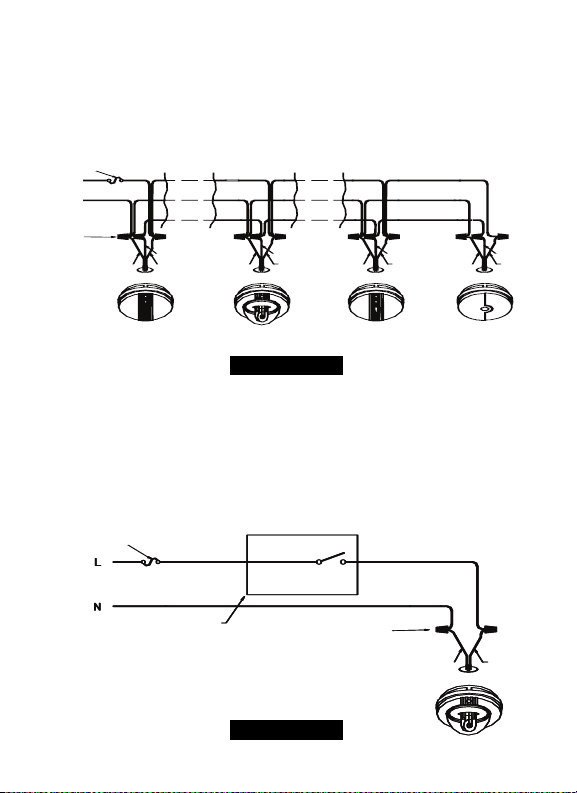
5. Figure 1 illustrates interconnection wiring. Improper connection will result in
damage to the strobe light or alarms, failure to operate, or a shock hazard.
6. Make certain that all devices in the interconnect system are wired to a contin-
uous (non-switched, non-GFI or GCFI protected) power line.
FIGURE 1
FIGURE 1: INTERCONNECT WIRING DIAGRAM FOR SL177i.
WIRE ON STROBE LIGHT HARNESS CONNECTED TO:
BLACK . . . . . . . . . .HOT SIDE OF AC LINE
WHITE . . . . . . . . . .NEUTRAL AC LINE
RED . . . . . . . . . . . .INTERCONNECT LINES (RED WIRES) OF THE OTHER UNITS
IN THE MULTIPLE STATION SET UP
FIGURE 2
Page 7

FIGURE 2: MODEL SL177 WIRING INSTRUCTIONS FOR AC QUICK
CONNECT 2-WIRE HARNESS.
Figure 2 illustrates the proper SL177 wiring. Improper connection will result in
damage to the strobe light or alarms, failure to operate, or a shock hazard.
WIRE ON STROBE LIGHT HARNESS CONNECTED TO:
BLACK . . . . . . . . . .HOT SIDE OF AC LINE
WHITE . . . . . . . . . .NEUTRAL AC LINE
MOUNTING INSTRUCTIONS:
• A trim ring is provided on the back of the strobe light. This trim ring is
installed on the electrical box between the electrical box and the strobe light.
• Remove the trim ring from the back of the strobe light by holding the trim
ring and twisting the strobe light in the direction indicated by the "OFF"
arrow on the cover.
CAUTION THIS UNIT IS SEALED. THE COVER IS NOT REMOVABLE! After selecting
the proper strobe light location as described in section 3, and wiring the AC
QUICK CONNECT harness as described in the WIRING INSTRUCTIONS, attach the
trim ring to the electrical box (see fig. 3).
Rectangular
Plaster Ring
Circular
Plaster Ring
FIGURE 3
Octagonal
Electrical Box
FIGURE 3: SELECT PROPER MOUNTING HOLES ON THE TRIM RING
• Use a screwdriver to punch out only the pair of holes in the trim ring that
match your type of electrical box or plaster ring. Mount the trim ring to the
electrical box using the appropriate holes. NOTE: Use the circle, square, and
octagon markings near each mounting hole in the trim ring to help you select
the correct mounting holes (see fig. 3).
Page 8

• Pull the AC QUICK CONNECTOR through the center hole in the ring and
mount the ring, making sure that the mounting screws are positioned in the
small ends of the keyholes before tightening the screws (see fig. 3).
• Plug the AC QUICK CONNECTOR into the back of the strobe light, (see fig. 4)
making sure that the locks on the connector snap into place.
To remove AC
connector,
squeeze
locking
arm and
pull.
Alignment Marks
Install
Remove
Tamper resistant
locking pin
FIGURE 4 FIGURE 5 FIGURE 6
• If you have finished all the WIRING AND TRIM RING MOUNTING STEPS, you
can install the strobe light on the trim ring. Alignment marks are provided on
the side of the strobe light and on the Install the strobe light on the trim ring
with the indicating marks aligned and rotate the detector in the direction of
the ON arrow on the cover until the strobe light snaps in place. (See fig. 5)
• Turn on the AC power, The model SL177i strobe light has a green AC power
on indicator which should be lit when the strobe is operating from AC power.
TAMPER RESIST LOCKING PIN: To make your strobe light tamper resistant a locking pin has been provided with your strobe light. Using this pin will help deter
individuals from removing the strobe light from the trim ring. To use the pin
insert it into the hole in the side of the strobe light after the strobe light has
been installed on the trim ring (see fig. 6). NOTE: The tamper resist pin will have
to be removed in order to remove the strobe light. This can be done easily with
a long nose pliers. Using the long nose pliers, pull the pin out of the hole, it is
now possible to remove the strobe light from the trim ring.
After installation TEST your strobe light by following the test procedure outlined
in section 6.
CAUTION! Early warning fire detection and visual notification is best achieved by
the installation of fire detection and visual notification equipment in all rooms
and areas of the household as follows: A smoke alarm and visual notification
Page 9

device installed and interconnected in each separate sleeping area, and visual
notification equipment interconnected with heat, smoke, or CO alarms in the living rooms, dining rooms, kitchens, hallways, attics, furnace rooms, closets, utility
storage rooms, basements, and attached garages.
6. TESTING AND OPERATION
WARNING! THIS STROBE LIGHT IS EXTREMELY BRIGHT. DO NOT LOOK
DIRECTLY AT THE LIGHT OR TOUCH THE LENS WHEN THE LIGHT IS FLASHING.
TESTING: Test by pushing the test button on one of the controlling alarms and
hold it down for a minimum of 5 seconds after the alarms sounds. This will
allow the controlling device to sound an alarm if all the electronics, circuitry, and
horn are working. The controlling alarm will also send an activation signal
through the interconnecting wiring to the strobe light, and cause the strobe
light to flash if strobe light and the interconnection wiring are working properly.
If no alarm sounds check the fuse or circuit breaker supplying power to the
alarm circuit.
If the alarm sounds but the strobe light does not activate, refer to section 5 to
insure that the strobe light is wired properly.
TEST THE STROBE LIGHT AND YOUR ALARMS WEEKLY TO ENSURE PROPER
OPERATION.
OPERATION: The strobe light is operating once AC power is applied, and testing
is complete. When the strobe light is activated, it will flash for as long as the
controlling alarm remains active.
7. MAINTENANCE
STROBE LIGHT REMOVAL:
IF TAMPER RESIST PIN HAS BEEN USED, REFER TO “TAMPER RESIST LOCKING
PIN” IN SECTION (5) FOR PIN REMOVAL INSTRUCTIONS.
CLEANING YOUR STROBE LIGHT:
To clean your Strobe light remove it from the mounting bracket and disconnect
the AC Quick Connect power harness as outlined in section 5.
You can clean dust from your strobe light by using a vacuum cleaner hose and
vacuuming around the cover and lens openings on the strobe light.
The outside of the strobe light can be wiped with a damp cloth.
Page 10

AFTER CLEANING, REINSTALL YOUR STROBE LIGHT AND TEST YOUR
STROBE LIGHT BY ACTIVATING ONE OF THE CONTROLLING ALARMS.
8. LIMITATIONS OF ALARM CONTROLLED VISUAL SIGNALING
DEVICES
VISUAL SIGNALING DEVICES CAN PROVIDE EARLY WARNING TO HEARING
IMPAIRED INDIVIDUALS AT A REASONABLE COST; HOWEVER, IN ORDER FOR
THE VISUAL SIGNALING DEVICE TO FUNCTION, IT MUST BE ACTIVATED BY AN
OPERATING ALARM. ALARMS CANNOT PROVIDE AN ACTIVATION SIGNAL TO
THE VISUAL SIGNALING DEVICE IF SMOKE, HEAT OR CARBON MONOXIDE DO
NOT REACH THE SPECIFIC ALARM. THEREFORE, ALARMS MAY NOT SENSE A
CONDITION ON A DIFFERENT FLOOR, OR ON THE OTHER SIDE OF A CLOSED
DOOR. ALARMS DO HAVE LIMITATIONS. AC POWERED ALARMS WILL NOT
OPERATE IF AC POWER HAS BEEN CUT OFF BY AN ELECTRICAL FIRE OR AN
OPEN FUSE.
HOME EMERGENCIES DEVELOP IN DIFFERENT WAYS AND ARE OFTEN UNPREDICTABLE. NO ONE TYPE OF CONTROLLING ALARM; HEAT, FIRE (IONIZATION OR
PHOTOELECTRIC) OR CARBON MONOXIDE IS ALWAYS BEST. FOR MAXIMUM
PROTECTION, ALARMS MUST BE INSTALLED IN EACH SLEEPING AREA, AND ON
EVERY LEVEL OF A HOME. ALARMS MUST BE INTERCONNECTED WITH EACH
OTHER AND THE SIGNALING DEVICES AND BE TESTED REGULARLY TO INSURE
THE ALARMS AND INTERCONNECTING CIRCUITS ARE IN GOOD OPERATING
CONDITION.
IN A UNDERWRITERS LABORATORIES STUDY, THIS TYPE OF VISUAL SIGNALING
APPLIANCE WAS ONLY SUCCESSFUL IN WAKING 92% OF THE SLEEPING
RESPONDENTS.
HEARING IMPAIRED INDIVIDUALS MAY NOT SEE THE VISUAL WARNING DEVICE
IF WALLS, DOORS, DISTANCE, HIGH AMBIENT LIGHT, OR OTHER OBSTRUCTIONS
BLOCK THE STROBE LIGHT. IF THE STROBE LIGHT IS LOCATED OUTSIDE THE
BEDROOM OR ON A DIFFERENT FLOOR, IT WILL NOT WAKE UP A SOUND
SLEEPER. THE USE OF ALCOHOL OR DRUGS MAY ALSO IMPAIR ONES ABILITY
TO RESPOND TO THE VISUAL SIGNAL.
ALTHOUGH VISUAL SIGNALING DEVICES CAN HELP SAVE LIVES BY PROVIDING
AN EARLY WARNING OF AN EMERGENCY SITUATION, THEY ARE NOT A SUBSTITUTE FOR AN INSURANCE POLICY. HOME OWNERS AND RENTERS SHOULD
HAVE ADEQUATE INSURANCE TO PROTECT THEIR LIVES AND PROPERTY.
Page 11

9. GOOD SAFETY HABITS
DEVELOP AND PRACTICE A PLAN OF ESCAPE
• Install and maintain Fire extinguishers on every level of the home and in the
kitchen, basement and garage. Know how to use a fire extinguisher prior to
an emergency.
• Make a floor plan indicating all doors and windows and at least two (2)
escape routes from each room. Second story windows may need a rope or
chain ladder.
• Have a family meeting and discuss your escape plan, showing everyone what
to do in case of fire.
• Determine a place outside your home where you all can meet if a fire occurs.
• Familiarize everyone with the sound of the smoke alarm and train them to
leave your home when they hear it.
• Practice a fire drill at least every six months, including fire drills at night.
Ensure that small children hear the alarm and wake when it sounds. They
must wake up in order to execute the escape plan. Practice allows all occupants to test your plan before an emergency. You may not be able to reach
your children. It is important they know what to do.
• Current studies have shown smoke alarms may not awaken all sleeping individuals, and that it is the responsibility of individuals in the household that are
capable of assisting others to provide assistance to those who may not be
awakened by the alarm sound, or to those who may be incapable of safely
evacuating the area unassisted.
WHAT TO DO WHEN THE ALARM SOUNDS
• Alert small children in the home.
•
Leave immediately by your escape plan. Every second counts, so don’t waste
time getting dressed or picking up valuables.
• In leaving, don’t open any inside door without first feeling its surface. If hot,
or if you see smoke seeping through cracks, don’t open that door! Instead,
use your alternate exit. If the inside of the door is cool, place your shoulder
against it, open it slightly and be ready to slam it shut if heat and smoke rush
in.
• Stay close to the floor if the air is smoky. Breathe shallowly through a cloth,
wet if possible.
Page 12

• Once outside, go to your selected meeting place and make sure everyone is
there.
• Call the fire department from your neighbor’s home - not from yours!
• Don’t return to your home until the fire officials say that it is all right to do so.
There are situations where a smoke alarm may not be effective to protect
against fire as stated in the NFPA Standard 72. For instance:
a) smoking in bed
b) leaving children home alone
c) cleaning with flammable liquids, such as gasoline
10. NFPA REQUIRED PROTECTION
For your information the National Fire Protection Association's Standard 72, provides information regarding the fire detection equipment required within the
family living unit. And reads as follows:
Smoke Detection. Where required by applicable laws, codes, or standards for the
specified occupancy, approved single- and multiple-station smoke alarms shall be
installed as follows: (1) In all sleeping rooms Exception: Smoke alarms shall not
be required in sleeping rooms in existing one- and two-family dwelling units. (2)
Outside of each separate sleeping area, in immediate vicinity of the sleeping
rooms. (3) On each level of the dwelling unit, including basements Exception: In
existing one- and two-family dwelling units, approved smoke alarms powered by
batteries are permitted.
Smoke Detection - Are More Smoke Alarms Desirable? The required number of
smoke alarms might not provide reliable early warning protection for those areas
separated by a door from the areas protected by the required smoke alarms. For
this reason, it is recommended that the householder consider the use of additional smoke alarms for those areas for increased protection. The additional
areas include the basement, bedrooms, dining room, furnace room, utility room,
and hallways not protected by the required smoke alarms. The installation of the
smoke alarms in the kitchen, attic (finished or unfinished), or garage is normally
not recommended, as these locations occasionally experience conditions that
can result in improper operation.
This equipment should be installed in accordance with the National Fire
Protection Association’s Standard 72 (NFPA, Batterymarch Park, Quincy, MA
02269).
Page 13

NOTIFY YOUR LOCAL FIRE DEPARTMENT AND INSURANCE COMPANY OF YOUR
SMOKE ALARM INSTALLATION.
11. SERVICE AND WARRANTY
If after reviewing this manual you feel that your Visual Signaling Device is defective in any way, do not tamper with the unit. Return it for servicing to: KIDDE
SAFETY, 1016 Corporate Park Dr., Mebane, NC. 27302 (See Warranty for in-warranty returns).
Page 14

FIVE YEAR LIMITED WARRANTY
KIDDE Safety warrants the original purchaser that the enclosed Visual signaling Device
will be free of defects in material and workmanship or design under normal use and
service for a period of five years from the date of purchase. The obligation of KIDDE
Safety under this warranty is limited to repairing or replacing the Visual Signaling Device
or any part which we find to be defective in material, workmanship or design, free of
charge to the customer, upon sending the Visual Signaling Device with proof of date of
purchase, postage and return postage prepaid to: Warranty Service Department, Kidde
Safety, 1016 Corporate Park Dr., Mebane, NC 27302.
This warranty shall not apply to the Visual Signaling Device if it has been damaged,
modified, abused, or altered after the date of purchase or if it fails to operate due to
inadequate AC electrical power.
THE LIABILITY OF KIDDE SAFETY OR ANY OF ITS PARENT OR SUBSIDIARY CORPORATIONS ARISING FROM THE SALE OF THIS VISUAL SIGNALING DEVICE OR UNDER THE
TERMS OF THIS LIMITED WARRANTY SHALL NOT IN ANY CASE EXCEED THE COST OF
REPLACEMENT OF THE VISUAL SIGNALING DEVICE, AND IN NO CASE SHALL KIDDE
SAFETY OR ANY OF ITS PARENT OR SUBSIDIARY CORPORATIONS BE LIABLE FOR CONSEQUENTIAL LOSS OR DAMAGE RESULTING FROM THE FAILURE OF THE VISUAL SIGNALING DEVICE OR THE BREACH OR THIS OR ANY OTHER WARRANTY, EXPRESSED OR
IMPLIED, EVEN IF THE LOSS IS CAUSED BY THE COMPANIES NEGLIGENCE OR FAULT.
Since some states do now allow limitations on the duration of an implied warranty or do
now allow the exclusion of limitations or incidental or consequential damages, the above
limitation or exclusions may not apply to you. While this warranty gives you specific legal
rights, you may also have other rights which vary from state to state.
The above warranty may not be altered except in writing signed by both parties hereto.
QUESTIONS OR FOR MORE INFORMATION
Call our Consumer Hotline at 1-800-880-6788 or contact
us at our website at www.kidde.com
Kidde, 1016 Corporate Park Drive, Mebane, NC 27302
Page 15

Luz
For models: SL 177i and SL 177
estroboscópica
Guía del usuario de la luz estroboscópica
¡ATENCIÓN! Los modelos de luz estroboscópica SL177 y SL 177i están diseñados para avisar a las personas con
discapacidad auditiva del peligro inminente;estas luces no cuentan con ningún medio de detección y DEBEN ser
usadas conjuntamente con alarmas de monóxido de carbono,térmicas,o contra humo.
El modelo SL177i con luz estroboscópica cableada para CA puede interconectarse directamente a las alarmas de
CO,térmicas y contra humo de 3 hilos de Kidde Safety.La unidad prenderá una luz intermitente (titilará aproximadamente 4 veces,y luego se apagará durante 5 segundos) cuando sea activada por la alarma de monóxido de
carbono,y prenderá una luz permanente cuando sea activada por la alarma contra humo o térmica.
El modelo SL177 es un dispositivo de 2 hilos que puede usarse para añadir la particularidad de la luz estroboscópica a los sistemas de detección existentes y fabricados por otros fabricantes.Se necesitará un modulo relé o conmutador adecuado (no se incluye), compatible con el sistema de detección para activar la luz estroboscópica. Consulte
con el fabricante de la alarma para obtener el conmutador adecuado para su modelo de alarma específico.
Gracias por comprar esta luz estroboscópica.Forma una parte importante en el plan de seguridad de su
hogar.Puede confiar que KIDDE Safety brinda los productos de seguridad de mayor calidad. Sabemos
que no puede esperar menos cuando la vida de su familia está en juego.
Para su conveniencia,escriba la siguiente información. Si llama a nuestra
línea de ayuda al cliente, estas son las primeras preguntas .
Número del modelo de la luz estroboscópica
ubicado en la parte posterior de la alarma
(
Código de fecha (ubicado en la parte
posterior de la alarma): La Asociación
Nacional de Protección contra Incendios
(NFPA) y el fabricante recomiendan reemplazar esta alarma en diez años contados
desde el código de la fecha.
Fecha de compra:
Lugar de compra
:
:
SL 177 SL 177i
):
P/N 810-1779 Rev.B
Page 16

¡IMPORTANTE! LEA TODAS LAS INSTRUCCIONES ANTES DE INSTALAR LA
UNIDAD Y GUARDE ESTE MANUAL PARA REFERENCIAS FUTURAS
¡ADVERTENCIA! ESTE DISPOSITIVO DE SEÑALIZACIÓN VISUAL NO CUENTA CON MECANISMOS DE DETECCIÓN. IT MUST BE USED IN CONJUNCTION WITH OPERATING ALARMS.DEBE USARSE CONJUNTAMENTE CON
LAS ALARMAS EN FUNCIONAMIENTO.
¡ADVERTENCIA! NO INTENTE REPARAR LA LUZ ESTROBOSCÓPICA USTED
MISMO. ESTE DISPOSITIVO CONSTA DE NIVELES ENERGÉTICOS DE ALTO
VOLTAJE LO CUAL PUEDE MATARLO. CONSULTE LAS INSTRUCCIONES EN
LA SECCIÓN 11 SOBRE REPARACIONES.
¡ADVERTENCIA! LA DESCONEXIÓN O PERDIDA DE ALIMENTACIÓN DE CA
AFECTARÁ EL DISPOSITIVO DE SEÑALIZACIÓN.
¡ADVERTENCIA! ESTA LUZ ESTROBOSCÓPICA ES EXTREMADAMENTE
BRILLANTE. NO MIRE DIRECTAMENTE A LA LUZ NI TOQUE LOS LENTES
CUANDO LA LUZ ESTÉ TITILANDONG
CONTENIDO DE ESTE MANUAL
1 -- ESPECIFICACIONES
2 -- USOS
3 -- USOS RECOMENDADOS PARA LA LUZ ESTROBOSCÓPICA
4 -- ÁREAS A EVITAR
5 -- INSTRUCCIONES DE INSTALACIÓN
6 -- FUNCIONAMIENTO Y PRUEBA
7 -- MANTENIMIENTO
8 -- RESTRICCIONES DE LOS DISPOSITIVOS DE SEÑALIZACIÓN PARA LAS
PERSONAS CON DISCAPACIDAD AUDITIVA
9 -- BUENOS HÁBITOS DE SEGURIDAD
10 -- NORMA DE PROTECCIÓN 72 DE LA NFPA (ASOCIACIÓN NACIONAL
DE PROTECCIÓN CONTRA INCENDIOS)
11 -- SERVICIO TÉCNICO Y GARANTÍA
1. ESPECIFICACIONES
Número del modelo: SL177i (UNIDAD INTERCONECTADA DE 3 HILOS)
Régimen eléctrico: Aplicación especial 110—130 VCA
Corriente máxima de funcionamiento RMS 420 mA
Page 17

Nota: Este dispositivo fue probado sólo sobre un alcance de 110-130 VAC.No considere el
80% ni el 110% de estos alcances durante la instalación ya que el dispositivo no fue probado
para usarse con los mismos.
La unidad de inter
ta directamente con Kidde Safety:
Modelos de alarmas contra 1235,1235CA, 1275, 1275CA, 1276, 1276CA, 1285,
humo/de ionización:
Alarmas contra humo PE120,PE120CA,
fotoeléctricas:
Alarmas contra humo PI12000,PI2000CA
fotoeléctricas/de ionización:
Modelos de alarmas térmicas: HD135F,HD135FCA
Modelos de alarmas contra KN-COSM-I,KN-COSM-IB,
humo CO/de ionización: KN-COSM-ICA, KNCOSM-IBCA
Modelos de alarmas de monóxido KN-COB-IC,KN-COB-IC-CA,
de carbono: KN-COB-ICB-CA, KN-COP-IC, KN-COP-IC-CA
Frecuencia de la luz intermitente 1 luz intermitente constante por segundo nominal
(en caso de activación de la
alarma contra humo):
Frecuencia de la luz intermitente 1 luz intermitente por segundo nominal (titila
(encaso de activación de la alarma aproximadamente 4 veces,y luego permanece
de CO): APAGADA durante 5 segundos)
Número del modelo: SL177 (UNIDAD DE CONEXIÓN DIRECTA tipo 2 HILOS)
Régimen eléctrico: Aplicación especial 110—130 VCA
Nota: Este dispositivo fue probado sólo sobre un alcance de 110-130 VAC.No considere el
80% ni el 110% de estos alcances durante la instalación ya que el dispositivo no fue probado
para usarse con los mismos.
Frecuencia de la luz intermitente:
Número del modelo: SL177i y SL177
Límites de la temperatura: De 32˚F (0˚C) a 120˚F (49˚C)
Montaje: Pared o techo
Usos: Primario directo o indirecto y suplementario
Salida de la luz: Candela mínima 177 (en medida axial)
El siguiente diagrama muestra como la intensidad de la luz disminuye gradualmente a medida
que aumenta el ángulo visual. Use esta información para determinar la mejor ubicación de la
luz estroboscópica.
conexión para estaciones múltiples (24), se interconec-
1285CA, 1296, i12020, i12020CA, i12040, i12040CA,
i12060, i12060CA, i12080, RF-SM-ACDC
Corriente máxima de funcionamiento RMS 389 mA
1 luz intermitente constante por segundo nomina
l
Page 18

2. USOS
WALL
CEILING
25 90
25 85
30 80
30 75
35 70
35 65
40 60
45 55
55 50
75 30-45
90 5-25
100 0
(LIGHT INTENSITY) (IN DEGREES)
PERCENT ANGLE
90°
90°
90° 90°
0°
0°
45°
45°
45° 45°
SOURCE
LIGHT
SOURCE
LIGHT
WALL
CEILING
25 90
25 85
30 80
30 75
35 70
35 65
40 60
45 55
55 50
75 30-45
90 5-25
100 0
(LIGHT INTENSITY) (IN DEGREES)
PERCENT ANGLE
90°
90°
90° 90°
0°
0°
45°
45°
45° 45°
SOURCE
LIGHT
SOURCE
LIGHT
SEÑAL VISUAL PRIMARIA DIRECTA E INDIRECTA
Ubique la luz estroboscópica en el techo del cuarto,en la parte central del cuarto o en
la pared a una distancia mínima de 80 in. (2 m) sobre el piso. Para los cuartos con
una dimensión superior a los 250 pies cuadrados (14 ft.x 16 ft. - 4.27 m x 4.88 m) el
aviso del dispositivo debe colocarse a 16 ft. (4.88 m) de la almohada.
SEÑAL VISIBLE SUPLEMENTARIA
La luz estroboscópica debe ubicarse a menos de 80 in. (2 m) de distancia del piso.
3. ÁREAS RECOMENDADAS PARA UBICAR LOS DISPOSITIVOS DE
SEÑALIZACIÓN VISUAL
• Coloque la primera luz estroboscópica en el dormitorio designado para la persona con discapacidad auditiva.Si la puerta del dormitorio permanece cerrada durante la noche,se debe
instalar una alarma contra humo interconectada con ese dormitorio.
Ubique las luces estroboscópicas adicionales en cualquier cuarto donde la persona con incapaci-
•
dad auditiva necesite ser notificada sobre el alerta de una alarma.
4. ÁREAS A EVITAR
• En áreas donde se percibe la luz directa del sol o en las áreas demasiado iluminadas ya que
la luz brillante puede impedir que una persona vea la luz estroboscópica
• En áreas donde la temperatura puede disminuir por debajo de los 32°F (4.4°C) o aumentar
por encima de los 100°F (37.8°C).
• En áreas con mucha humedad.
•
5. INSTRUCCIONES DE INSTALACIÓN
LEA CUIDADOSAMENTE – REQUERIMIENTOS PARA EL CABLEADO
• Esta alarma contra humo debe instalarse en una caja de conexiones registrada o UL
En las áreas exteriores (este dispositivo no está calificado para usarse en exteriores).
homologada.
do debe realizarse de acuerdo a lo establecido en los artículos 210 y 300.3 (B) del Código
Todas las conexiones deben realizarse por un electricista calificado y el cablea-
de Electricidad Nacional de EE.UU.ANSI/NFPA 70,NFPA 72 y/o cualquier otro código aplicable en su área. El cableado para interconectar estaciones múltiples a las alarmas debe pasar
Page 19

por el mismo conducto eléctrico o cable que el cableado de alimentación de CA.Además, la
resistencia del cableado de interconexión será de 10 ohms como máximo.
• El generador adecuado es un monofásico de 110-130 voltios para CA abastecido por un circuito no conmutado,el cual no está protegido por un interruptor de pérdida a tierra.
INSTRUCCIONES PARA EL CABLEADO DEL MODELO SL 177I Para MAZO DE 3 HILOS DE CONEXIÓN
RÁPIDA DE CA
ADVERTENCIA:Esta alarma no puede operarse desde un generador derivado de un inversor de
onda cuadrada,onda cuadrada modificada u onda senoidal. Estos tipos de inversores a veces
se utilizan para suministrar energía al sistema de paneles fotovoltaicos,como fuentes de
energía solar y eólica. Estas fuentes de energía producen voltajes máximos que dañarán la
alarma.
¡PRECAUCIÓN! APAGUE EL SUMINISTRO DE ENERGÍA PRINCIPAL DEL CIR-
CUITO ANTES DE REALIZAR EL CABLEADO DE LA LUZ
ESTROBOSCÓPICA.
Cuando las alarmas y las luces estroboscópicas estén interconectadas,todos los dispositivos
1.
interconectados deben quedar alimentados por el mismo circuito.
2. Se puede interconectar un máximo de 24 dispositivos Kidde Safety en un sistema de esta-
ciones múltiples.El sistema interconectado no debe exceder los límites de interconexión de 12
alarmas contra humo y/o 18 alarmas en total,según lo establece el NFPA (contra humo,térmica, monóxido de carbono, etc.). Con 18 alarmas interconectadas, es posible interconectar
hasta un total de 6 módulos relé y/o dispositivos de señalización a control remoto.
NOTA: CUANDO SE MEZCLAN LOS MODELOS CON PILA DE EMERGENCIA (1275, 1275CA,
1276, 1276CA, 1285, 1296, i12040, i12040CA, i12060, i12060CA, i12080, PE120, PE120CA,
PI2000, PI2000CA, KN-COSM-IB, KN-COSM-IBCA,RFSM- ACDC, HD135F,HD135FCA, KNCOB-IC,KN-COB-IC-CA, KN-COP-IC,KNCOP- IC-CA) CON LOS MODELOS SIN PILA DE EMERGENCIA (1235, 1235CA, i12020, i12020CA, KN-COSM-I, KN-COSM-ICA, KN-COB-ICB-CA,
CO120X, SM120X Y SL177i),TENGA EN CUENTA QUE LOS MODELOS SIN PILA DE EMERGENCIA NO FUNCIONARÁN DURANTE UN CORTE DE ENERGÍA.
4. El recorrido máximo del cable entre el primer y el último dispositivo en un sistema inter-
conectado es de 1000 pies (300 m).
5. La figura 1 ilustra el cableado de interconexión. Una conexión inadecuada dañará la luz
estroboscópica o las alarmas,impedirá el funcionamiento de la unidad u ocasionará una
descarga eléctrica.
Asegúrese de que todos los dispositivos del sistema interconectado estén cableados a una línea
6.
continua de alta tensión (sin interruptor, sin protección GFI o GCFI).
Page 20

FIGURA 1: DIAGRAMA DE CABLEADO INTERCONECTADO DEL MODELO SL177i:
N
L
BLANCO
NEGRO
ROJO
Fusible o circuito del interruptor
Alarma contra humo
Luz estroboscópica
Alarma de calor
Alarma contra
monóxido de carbono
BLANCO
NEGRO
ROJO
BLANCO
NEGRO
ROJO
BLANCO
NEGRO
ROJO
NEGRO
BLANCO
Interruptor aparato
controlar el SL177
luz estroboscópica
Fusible o circuito del interruptor
FIGURA 1
EL CABLE EN EL CABLEADO DE LA LUZ ESTROBOSCÓPICA ESTÁ CONECTADO A:
NEGRO . . . . . . . . LADO CALIENTE DE LA LÍNEA DE CA
BLANCO . . . . . . . .LÍNEA DE CA NEUTRA
ROJO ..........
LÍNEAS INTERCONECTADAS (CABLES ROJOS) DE LAS DEMÁS UNIDADES
FIGURA 2: INSTRUCCIONES DE CABLEADO DEL MODELO SL177 PARA
MAZO DE 2 HILOS DE CONEXIÓN RÁPIDA DE CA.
a 2 se ilustra el cableado correcto del modelo SL177.Una conexión inadecuada
En la figur
FIGURE 2
dañará la luz estroboscópica o las alarmas,impedirá el funcionamiento de la unidad u ocasionará una descarga eléctrica.
EL CABLE EN EL CABLEADO DE LA LUZ ESTROBOSCÓPICA ESTÁ CONECTADO A:
NEGRO . . . . . . . . LADO CALIENTE DE LA LÍNEA DE CA
BLANCO . . . . . . . . LÍNEA DE CA NEUTRA
Page 21

INSTRUCCIONES PARA EL MONTAJE:
• La luz estroboscópica incluye un anillo de ajuste en la parte tr
asera.Este anillo de ajuste se
instala en la caja eléctrica entre esta última y la luz estroboscópica.
• Quite el anillo de ajuste ubicado en la parte trasera de la luz estroboscópica,sosteniendo el
anillo de ajuste y girando la luz en la dirección que indica la flecha “OFF”en la tapa.
PRECAUCIÓN:ESTA UNIDAD ESTÁ SELLADA. ¡NO SE PUEDE QUITAR LA TAPA! Luego de elegir
la ubicación apropiada de la luz estroboscópica, según se describe en la sección 3, y luego de
haber realizado el cableado del mazo de CONEXIÓN RÁPIDA DE CA, según se describe en las
INSTRUCCIONES DE CABLEADO,fije el anillo de ajuste a la caja eléctrica (vea la fig. 3).
FIGURA 3: ELIJA LOS AGUJEROS DE MONTAJE CORRESPONDIENTES EN EL
ANILLO DE AJUSTE
• Use el destornillador para ahuecar sólo el par de agujeros en el anillo de ajuste que correspondan a su tipo de caja eléctrica o anillo de yeso
trica usando los agujeros correspondientes.NOTA:Use las marcas octogonales, cuadradas y
. Monte el anillo de ajuste a la caja eléc-
circulares cerca de cada agujero de montaje del anillo de ajuste para elegir los agujeros de
montaje correspondientes (vea la fig. 3).
Hale el CONECTOR RÁPIDO PARA CA a través del agujero central del anillo y monte este último,
•
asegurándose de que los tornillos de montaje estén ubicados en los extremos pequeños de los
orificios antes de ajustar los tornillos (vea la fig. 3).
Anillo de yeso
rectangular
Anillo de yeso
circular
FIGURA 3
Caja eléctrica
octagonal
• Enchufe el CONECTOR RÁPIDO PARA CA en la parte trasera de la luz estroboscópica (vea la
fig. 4), asegurándose de que las trabas del conector enganchen en el lugar.
• Si ha finalizado con los PASOS DE MONTAJE DEL AÑILLO DE AJUSTE Y EL CABLEADO,puede
instalar la luz estroboscópica en el anillo de ajuste.Las marcas de alineación se encuentran a
los costados de la luz estroboscópica y el anillo de ajuste.Instale la luz estroboscópica con
las marcas de indicación alineadas y gire la alarma en la dirección que va la flecha “ON”,
ubicada en la tapa, hasta que la luz estroboscópica enganche en el lugar. (Vea la fig. 5)
• Encienda el sistema de alimentación de CA. El modelo de luz estroboscópica SL177i cuenta
con un indicador verde de alimentación de CA en el que se encenderá cuando la luz esté
funcionando mediante el suministro de CA.
Page 22

CLAVIJA DE SEGURIDAD A PRUEBA DE MANIPULACIÓN:Para que la luz estroboscópica sea a
prueba de manipulación se le ha incluido una clavija de seguridad. El usar esta clavija
impedirá que ciertas personas quiten la luz estroboscópica del anillo de ajuste.Para usar la
clavija, insértela en el agujero ubicado al costado de la luz estroboscópica luego de que ésta
haya sido instalada en el anillo de ajuste (vea la fig.6). NOTA:La clavija a prueba de manipulación debe quitarse para poder quitar la luz estroboscópica.Esto puede realizarse fácilmente
con alicates de punta larga. Con el alicate de punta larga, hale la clavija del agujero, y luego
quite la luz estroboscópica del anillo de ajuste.Luego de la instalación, PRUEBE la luz estroboscópica aplicando el procedimiento de prueba detallado en la sección 6.
Para retirar el
conector de
CA, apriete
los brazos de
cierre y tire
Marcas de alineación
Instale
Remueva
Pasador de seguridad
contra la manipulación
indebida
FIGURA 4 FIGURA 5 FIGURA 6
¡PRECAUCIÓN! Una detección y aviso visual de incendio anticipado es más efectivo si se
instala un equipo de detección de incendio y aviso visual en todas las habitaciones y las áreas
de la vivienda. Se debe proceder a la instalación de la siguiente manera: Una alarma contra
humo y aviso visual para instalados e interconectados en cada dormitorio,y el equipo de aviso
visual interconectado con la alarma contra humo,térmica o CO en el living, comedor, cocina,
pasillos,áticos, cuartos de calefacción, lavaderos, sótanos y garajes anexos.
6. PRUEBA Y FUNCIONAMIENTO
¡ADVERTENCIA! ESTA LUZ ESTROBOSCÓPICA ES EXTREMADAMENTE BRILLANTE. NO MIRE DIRECTAMENTE A LA LUZ NI TOQUE LOS LENTES CUANDO
LA LUZ ESTÉ TITILANDO.
PRUEBA: Realice la prueba presionando el botón de prueba ubicado en uno de las alarmas de
control y manténgalo apretado durante un mínimo de 5 segundos después de que la alarma
a sonado.Esto permitirá al dispositivo de control que suene la alarma si todos los elec-
hay
trónicos,circuitos y pitillos funcionan. La alarma de control enviará una señal de activación a
través de los cables de interconexión a la luz estroboscópica,haciendo que esta última titile,
siempre y cuando el cableado de interconexión y la luz estén funcionando correctamente.Si no
suena la alarma, revise el fusible o el disyuntor que suministra energía al circuito de la alarma.
Si la alarma suena pero la luz estroboscópica no se activa,consulte la sección 5 para asegurarse de que el cableado de esta última esté correctamente realizado.
PRUEBE LA LUZ ESTROBOSCÓPICA YLA ALARMA CADA SEMANA PARA ASEGURARSE DE
QUE ESTÉN FUNCIONANDO BIEN.
Page 23

FUNCIONAMIENTO:La luz estroboscópica comienza a funcionar una vez que se suministra la
tensión de CA, y se completa la prueba. Cuando la luz estroboscópica se activa, ésta titilará
siempre y cuando la alarma de control permanezca activa.
7. MANTENIMIENTO
CÓMO QUITAR LA LUZ ESTROBOSCÓPICA:
SI SE HA UTILIZADO UNA CLAVIJA A PRUEBA DE MANIPULACIÓN,CONSULTE LA SECCIÓN
(5):“CLAVIJA DE SEGURIDAD A PRUEBA DE MANIPULACIÓN”PARA INFORMARSE SOBRE
LAS INSTRUCCIONES DE CÓMO QUITAR LA CLAVIJA.
COMO LIMPIAR LA LUZ ESTROBOSCÓPICA:
Para limpiar la luz estroboscópica quítela del soporte de montaje y desconecte el mazo de
conexión rápida para CA según se detalla en la sección 5.Puede desempolvar la luz estroboscópica usando una manguera de aspiradora y aspirar alrededor de la tapa y las aberturas
de los lentes de la luz estroboscópica. La parte externa de la luz estroboscópica puede
limpiarse con un paño húmedo.
LUEGO DE LIMPIAR LA UNIDAD, VUELVA A INSTALAR LA LUZ
ESTROBOSCÓPICA Y PRUÉBELA ACTIV
CONTROL.
ANDO UNO DE LAS ALARMAS DE
8. RESTRICCIONES DE LAS ALARMAS CONTROLADAS POR DIS-
POSITIVOS DE SEÑALIZACIÓN VISUAL
LOS DISPOSITIVOS DE SEÑALIZACIÓN VISUAL,DE COSTO RAZONABLE, PUEDEN ALERTAR DE
ANTEMANO A LAS PERSONAS CON INCAPACIDADES AUDITIVAS;SIN EMBARGO,PARA QUE
EL DISPOSITIVO DE SEÑALIZACIÓN VISUAL FUNCIONE,DEBE SER ACTIVADO POR LA ALARMA
DE FUNCIONAMIENTO. LAS ALARMAS NO PUEDEN EMITIR UNA SEÑAL DE ACTIVACIÓN AL
DISPOSITIVO DE SEÑALIZACIÓN VISUAL SI EL HUMO,CALOR O MONÓXIDO DE CARBONO NO
ES DETECTADO POR LA ALARMA CORRESPONDIENTE. POR LO TANTO, LAS ALARMAS NO
PUEDEN DETECTAR UNA SITUACIÓN ESPECÍFICA EN UN PISO DIFERENTE DE DONDE OCURRE
EL HECHO,O AL OTRO LADO DE UNA PUERTA CERRADA. LAS ALARMAS TIENEN RESTRICCIONES.LAS ALARMAS ALIMENTADAS POR CA NO FUNCIONARÁN SI SE CORTÓ LA
ALIMENTACIÓN DE CA DEBIDO A UN INCENDIO ELÉCTRICO O FUSIBLE DE TIPO DESCUBIERTO.
LAS EMERGENCIAS HOGAREÑAS OCURREN POR DIFERENTES RAZONES Y GENERALMENTE
SON IMPREDECIBLES.NINGÚN TIPO DE ALARMA DE CONTROL,YASEA TÉRMICA, CONTRA
INCENDIO O MONÓXIDO DE CARBONO (FOTOELÉCTRICA O DE IONIZACIÓN) ES EL MÁS
APROPIADO.PARA OBTENER UNA MÁXIMA PROTECCIÓN, SE DEBEN INSTALAR LAS ALARMAS EN CADA DORMITORIO,Y EN CADA PISO DE LA VIVIENDA.LAS ALARMAS DEBEN ESTAR
INTERCONECTADAS ENTRE SÍ Y LOS DISPOSITIVOS DE SEÑALIZACIÓN Y LOS MISMOS DEBEN
SER PROBADOS REGULARMENTE PARA ASEGURARSE DE QUE LAS ALARMAS Y LOS CIRCUITOS INTERCONECTADOS ESTÉN FUNCIONANDO BIEN.
IEN UN ESTUDIO LLEVADO A CABO POR UNDERWRITERS LABORATORIES,SE DETERMINÓ
QUE ESTE TIPO DE SEÑALIZACIÓN VISUAL LOGRÓ DESPERTAR SÓLO AL 92% DE LOS PARTICIPANTES DORMIDOS.
Page 24

LAS PERSONAS CON INCAPACIDAD AUDITIVA PUEDEN NO VER EL DISPOSITIVO DE PELIGRO
SI HAY OBSTRUCCIONES COMO:PAREDES,PUERTAS,DISTANCIA,AMBIENTES DEMASIADO
ILUMINADOS U OTROS OBJETOS QUE IMPIDAN VER LA LUZ ESTROBOSCÓPICA.SI LA LUZ
ESTROBOSCÓPICA ESTÁ UBICADA FUERA DEL DORMITORIO O EN UN PISO DIFERENTE,NO
DESPERTARÁ A UNA PERSONA PROFUNDAMENTE DORMIDA.EL USO DE ALCOHOL O DROGAS PUEDE AFECTAR LA CAPACIDAD DE LA PERSONA PARA RESPONDER A LA SEÑAL VISUAL.
A PESAR DE QUE LOS DISPOSITIVOS DE SEÑALIZACIÓN VISUAL PUEDEN AYUDAR A SALVAR
VIDAS YA QUE BRINDAN UN AVISO DE PELIGRO ANTICIPADO, NO PUEDE USÁRSELOS COMO
SUSTITUTOS DE UNA PÓLIZA DE SEGURO. LOS PROPIETARIOS DE VIVIENDAS E INQUILINOS
DEBEN POSEER UN SEGURO APROPIADO PARA PROTEGER LA PROPIEDAD Y SUS VIDAS.
9. BUENOS HÁBITOS DE SEGURIDAD
DESARROLLO Y PRÁCTICA DE UN PLAN DE EVACUACIÓN
• Instale y mantenga los matafuegos en cada piso de la vivienda y en la cocina, sótano y
aje.Aprenda como usar un matafuego antes de que ocurra una emergencia.
gar
• Haga un plano del lugar donde se indiquen todas las puertas y ventanas y al menos dos (2)
vías de evacuación desde cada cuarto.Las ventanas del segundo piso pueden requerir el uso
de una soga o escalera de cadena.
• Haga una reunión familiar, hable sobre el plan de evacuación y demuestre a cada uno lo
que debe hacer en caso de incendio.
• Establezca un lugar fuera de la casa donde se pueden reunir en caso de incendio.
• Familiarice a los integrantes con el sonido de la alarma contra humo y entrénelos para que
salgan de la vivienda cuando lo escuchen.
• Practique un simulacro de incendio al menos cada seis meses,incluyendo simulacros de
incendio durante la noche. Asegúrese de que los niños pequeños escuchen la alarma y se
despierten con el sonido.Deben despertarse para poder ejecutar el plan de evacuación. La
práctica permite a los ocupantes probar el plan implementado antes de que ocurra la emergencia. Puede que no tenga tiempo de socorrer a sus niños. Es importante que sepan que
hacer.
• Estudios actuales han demostrado que las alarmas contra humo no despertarán a todas las
personas dormidas,y que es responsabilidad de los habitantes de la vivienda ayudar a los
demás que no se hayan despertado con el sonido de la alarma,o aquellos que no puedan
evacuar de manera segura el área sin la asistencia de otra persona
QUE HACER CUANDO SUENA LA ALARMA
• Alerte a los niños pequeños de la casa.
• Deje la vivienda de inmediato implementando su plan de ev
no pierda tiempo vistiéndose o tratando de llevar objetos de valor.
• Al salir de la vivienda, no abra ninguna puerta interna sin primero palpar la superficie. Si
está caliente,o si ve que sale humo de las hendiduras, ¡no abra la puerta! En cambio, use la
salida alternativa.Si la parte interna de la puerta está fría, apoye su hombre contra la
misma, abra ligeramente y esté listo para cerrarla rápidamente si se viene una ola de calor o
humo.
acuación. Cada segundo cuenta,
Page 25

• Manténgase cerca del suelo si hay humo en el aire.Respire a través de un paño, mojado si
es posible..
• Una vez afuera,diríjase a su lugar de reunión y asegúrese de que todos estén ahí.
• Llame al departamento de bomberos desde la vivienda de su vecino - ¡nunca desde la suya!
• No regrese a su hogar hasta que los bomberos se lo permitan.
Hay situaciones en que la alarma contra humo no es efectiva en la protección contra incendios,según lo establece la norma 72 de la NFPA. Por ejemplo:
a) el fumar en una cama
b) dejar los niños solos en el hogar
c) limpiar con líquidos inflamables como la gasolina
10. PROTECCIÓN REQUERIDA POR LA NFPA
Para su información,la norma 72 de la Asociación Nacional de Protección contra Incendios,
proporciona información referente a los equipos de detección de incendios requeridos en las
viviendas familiares.Dicha información establece lo siguiente:
Detección de humo.Donde lo requiera la ley,las normas o los códigos aplicables a la ocupación específica de una vivienda, se deberán instalar las alarmas contra humo con estación
múltiple y simple aprobada de la siguiente manera:(1) En todos los dormitorios, excepto: No
se requerirá la instalación de alarmas contra humo en los dormitorios de una y dos viviendas
unifamiliares.(2) Afuera de cada dormitorio,y próximo a los mismos.(3) En cada nivel de la
vivienda unifamiliar, incluyendo el sótano, excepto: Se permite el uso de alarmas contra humo
accionadas con pilas y aprobadas en viviendas unifamiliares existentes.
Detección de humo - ¿Desea colocar otros alarmas contra humo? El número de alarmas contra
humo requerido puede no proporcionar un aviso de protección anticipado y confiable en las
áreas que se encuentran separadas por una puerta de las áreas protegidas por las alarmas
contra humo requeridas.Por esta razón,se recomienda que el propietario de la vivienda considere el uso de alarmas contra humo adicionales para las áreas que requieran mayor protección. Las áreas adicionales incluyen el sótano, dormitorios,comedor,cuarto de calefacción,
lavadero,y pasillos no protegidos por las alarmas contra humo requeridas.No se recomienda
la instalación de las alarmas contra humo en la cocina,ático (acabado o no), o garaje ya que
en estas áreas ocasionalmente se experimentan condiciones que pueden resultar en el funcionamiento incorrecto de la unidad.
Se debe instalar este equipo según la norma 72 de la Asociación Nacional de Protección contra Incendios (NFPANFPA, Batterymarch Park, Quincy, MA 02269).
NOTIFIQUE ASU DEPARTAMENTO DE BOMBEROS LOCAL Y COMPAÑÍA DE SEGUROS DE LA
INSTALACIÓN DE LA ALARMA CONTRA HUMO.
Page 26

11. SERVICIO TÉCNICO Y GARANTÍA
Si luego de leer este manual usted cree que su dispositivo de señalización visual presenta
algún tipo de defecto,no interfiera con la unidad. Devuélvala para su reparación a:KIDDE
SAFETY, 1016 Corporate Park Dr., Mebane, NC.27302 (Vea la garantía para las devoluciones
bajo la garantía).
FIVE YEAR LIMITED WARRANTY
KIDDE Safety warrants the original purchaser that the enclosed Visual signaling Device will be free of
defects in material and workmanship or design under normal use and service for a period of five years
from the date of purchase.The obligation of KIDDE Safety under this warranty is limited to repairing or
replacing the Visual Signaling Device or any part which we find to be defective in material,workmanship
or design, free of charge to the customer,upon sending the Visual Signaling Device with proof of date of
purchase,postage and return postage prepaid to:Warranty Service Department,Kidde Safety,1016
Corporate Park Dr., Mebane,NC 27302.
This warranty shall not apply to the Visual Signaling Device if it has been damaged, modified, abused, or
altered after the date of purchase or if it fails to operate due to inadequate AC electrical power.
THE LIABILITY OF KIDDE SAFETY OR ANY OF ITS PARENT OR SUBSIDIARY CORPORATIONS ARISING
FROM THE SALE OF THIS VISUAL SIGNALING DEVICE OR UNDER THE TERMS OF THIS LIMITED WARRANTY SHALL NOT IN ANY CASE EXCEED THE COST OF REPLACEMENT OF THE VISUAL SIGNALING
DEVICE,AND IN NO CASE SHALL KIDDE SAFETY OR ANY OF ITS PARENT OR SUBSIDIARY CORPORATIONS BE LIABLE FOR CONSEQUENTIAL LOSS OR DAMAGE RESULTING FROM THE FAILURE OF THE
VISUAL SIGNALING DEVICE OR THE BREACH OR THIS OR ANY OTHER WARRANTY, EXPRESSED OR
IMPLIED,EVEN IF THE LOSS IS CAUSED BY THE COMPANIES NEGLIGENCE OR FAULT.
Since some states do now allow limitations on the duration of an implied warranty or do now allow the
exclusion of limitations or incidental or consequential damages,the above limitation or exclusions may
not apply to you.While this warranty gives you specific legal rights,you may also have other rights
which vary from state to state.
The above warranty may not be altered except in writing signed by both parties hereto.
QUESTIONS OR FOR MORE INFORMATION
Call our Consumer Hotline at 1-800-880-6788 or contact
us at our website at www.kidde.com
Kidde,1016 Corporate Park Drive,Mebane, NC 27302
 Loading...