

Page 1
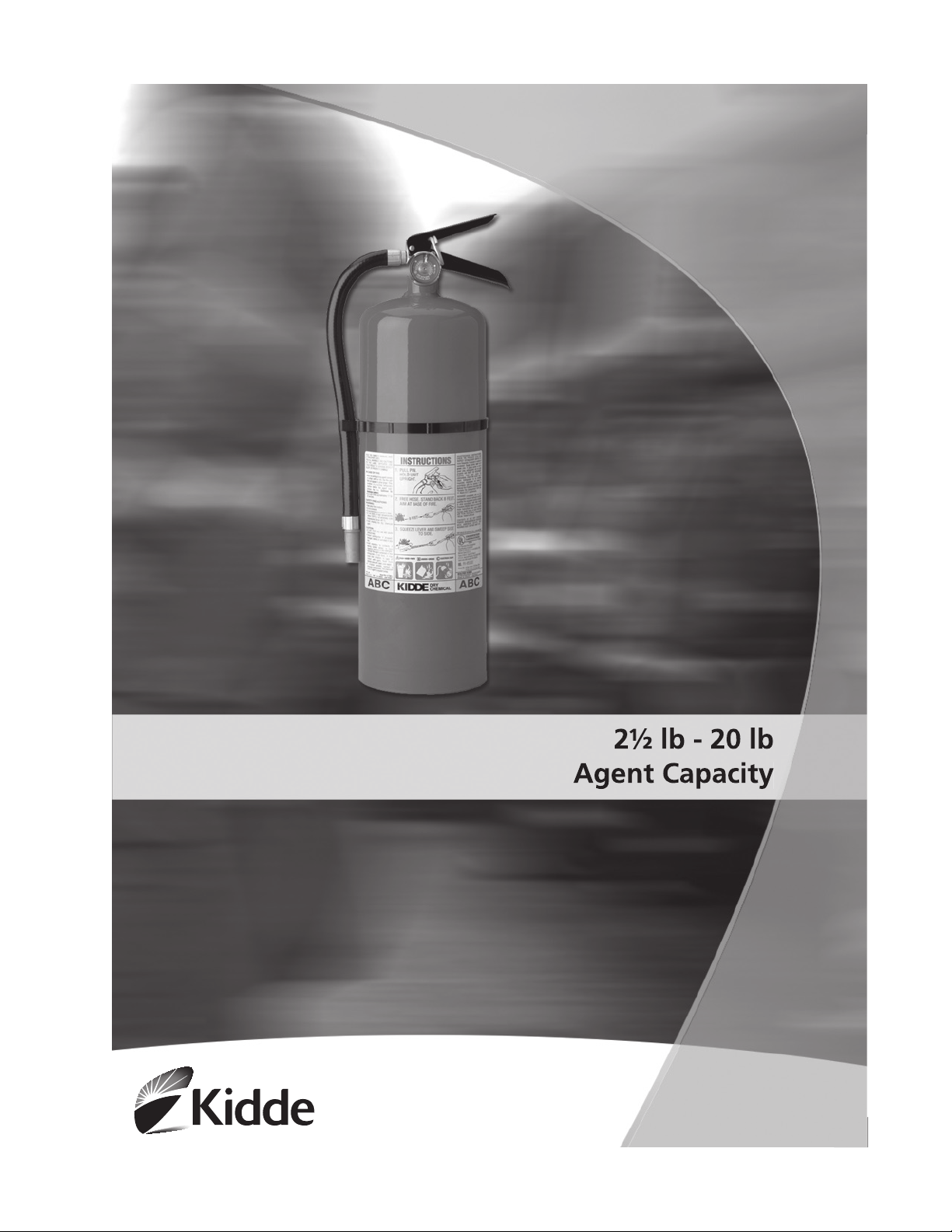
Pro Line
Service Manual
Stored Pressure
Dry Chemical
Hand Portable
Fire Extinguishers
Page 2
General Information
Descriptions
Page 3
www.nfpa.org www.bookstore.gpo.gov www.cganet.
the contents of the dry chemical charge.
- contains the dry chemical agent and expellant
charge.
Page 4
- consists of the operating lever, carrying
handle, valve stem, pressure gauge and discharge outlet that
permits the actuation and discharge of the dry chemical extinguishing
agent.
the means for the extinguishing agent to be drawn up from the
bottom of the cylinder to the discharge valve.
that the extinguisher has not been activated, charged or subjected to
tampering.
-provides a flexible means of agent
delivery from the discharge valve to the nozzle.
- provides the agent discharge stream shaping
characteristics necessary for optimum fire fighting performance.
position upwind of the fire.
while keeping the extinguisher in a vertical position, aim the nozzle
at the base of the fire.
the front edge of the fire.
initiate the agent discharge.
manner, being careful not to splash or scatter the fuel. Operators may
advance closer as control of the fire is gained however, they should
avoid stepping into the fuel or fire area.
re-flash.
removed and disposed of in accordance with any local handling
requirements.
Page 5

safe direction, squeeze the operating lever valve to clear hose and
vent all remaining pressure from the extinguisher.
extinguisher can be immediately recharged or a replacement
obtained.
that the extinguisher is fully charged and operable. This is done by
When circumstances require, more frequent intervals may be necessary.
is unobstructed.
instructions” face outward.
intact.
operable pressure range.
it is clear and unobstructed.
10 and local requirements.
Page 6

the maintenance or service of Kidde fire extinguishers. Refer to the
trouble shooting section of this manual for additional information on
WARNING:
readily accessible. Most Kidde dry chemical extinguisher models are
approved for temperature ranges between -40° F to +120° F.
mounting hardware is properly installed, secure and in good
operating condition.
service or dictate the need for any special maintenance/repair
procedures.
checked. The maximum periodic interval for Kidde dry chemical
stored pressure hand portable fire extinguishers is 12 years.
from the cylinder valve assembly and visually ensure it is not plugged
or obstructed. Closely examine the discharge nozzle, and/or hose
assembly (including hose crimp couplings) for any damage, wear or
conditions which might effect their proper function. Verify that the
Page 7

discharge nozzle, and/or hose assembly is correct for the model.
(Newer Kidde models indicate this information on their nameplates)
thread wear, corrosion, obstructions or accumulations of any foreign
material.
and replace if necessary. (For corrective action refer to the trouble
shooting section in this manual.)
(a) Ensure the gauge pressure needle indicates within the green
operable area.
(b) Visually ensure there is no external gauge damage, deformation,
dents or cracks.
(c) Verify gauge charge pressure properly correlates with charge
pressure on nameplate.
(d) Ensure gauge indicates proper compatibility for dry chemical
extinguishing agent.
(e) Ensure gauge indicates proper compatibility for use with either
aluminum or plated brass valve material.
damage or deformation, and ensure the rivets are secure.
and remove the ring pin breaking the visual inspection seal, to ensure
the ring pin functions freely and is not bent, damaged or corroded.
Re-install proper ring pin through the proper lever and valve ports,
then install a new visual inspection tamper seal through the pull pin
loop and around the carrying handle.
valve stem shaft is not bent, damaged or corroded. (The top of the
stem should extend from the valve body approximately 1/4 of an inch.)
nameplate operating instructions should face outward and be
orientated within 30 degrees of the pressure gauge face. Check to
ensure HMIS information is present and legible.
the discharge valves outlet port. Adjust and secure the hose nozzle
into the retention band clip (if equipped).
any damage and ensure it is properly adjusted to accommodate the
hose assembly nozzle.
weight falls within the tolerance limitations specified on the
nameplate instructions.
Page 8

dirt or contaminants that may have accumulated.
properly tag, label and record the procedure in accordance with
NFPA-10 and any local requirements.
that only the dry chemical extinguishing agent specified on the
in a safe direction, squeeze the operating valve lever to remove all
remaining pressure from the extinguisher. Check the extinguisher
gauge pressure reading to verify all pressure is removed.
corrosion or other conditions which might prohibit the unit from
being recharged.
the valve assembly.
WARNING:
Page 9

Disassemble the siphon tube and remove the spring and discharge
valve stem.
cracked or worn. Remove the O-ring and replace. Re-lubricate o-ring
with a light coat of silicone grease such as Vislox-V711 or equivalent.
O-ring and re-lubricate with a light coat of silicone grease such as
Vislox-V711 or equivalent.
stem, spring and siphon tube are correctly installed and securely
tightened.
and externally for any damage, thread wear, dents, repairs, corrosion,
discoloration or contaminants. If necessary remove extinguisher
from service and replace.
specified on the extinguisher nameplate recharge instructions.
the valve is properly snugged down and the pressure gauge is
properly orientated perpendicular to the front of the extinguisher.
discharge valve outlet port. Using a regulated source of dry nitrogen
containing a calibrated pressure gauge, depress operating lever
and slowly pressurize the extinguisher to pressure indicated on the
nameplate. Reference the calibrated pressurization gauge for proper
charge.
Page 10

shut off and remove the pressure source, then install the ring pin
into the valve assembly. Verify that the extinguisher gauge operating
pressure is also properly reading within the green operable area and
then install a visual inspection tamper seal through the ring
pin pull loop and around the top operating lever. Remove the
pressurization charge adapter from the extinguisher valve assembly.
leak check of the valve assembly, gauge and cylinder collar to ensure
no pressure leakage is occurring. Upon successful completion of the
leak check, properly clean and dry all extinguisher surfaces.
is not loose, damaged, worn or obstructed. Reinstall and secure the
nozzle and/or hose assembly into the discharge valves outlet
port. Adjust and secure the hose nozzle into the retention band clip if
equipped.
weight falls within the tolerance.
dirt or contaminates that may have accumulated.
accordance with NFPA-10 and all local requirements.
Page 11

thread wear, corrosion, cylinder repairs or physical damage as detailed
testing equipment, facilities and information.
has been weakened due to corrosion, cuts, dents, digs, etc.
then be flushed clean, dried and visually re-examined after testing.
testing of the cylinder. (Refer to Note in Step 5 of Recharge
instructions.)
utilize the proper type of record labels per NFPA-10 requirements.
additives or mediums other than that specified on the nameplate, it
should be removed from service and properly disposed at the owner’s
direction.
observed, the extinguisher should be removed from service and
properly disposed at the owner’s direction.
Page 12
Problem Corrective Suggestion
Wall hook/bracket loose or damaged Secure, repair or replace
Valve discharge port obstructed/dirty Clean or empty and replace
correlation.
recharge or replace*
dispose of in accordance with
NFPA-10
Page 13

Dry Chemical Extinguisher Parts Diagram - Aluminum Valve
excludes o-ring)
assembly, stem assembly spring)
Page 14

Dry Chemical Extinguisher Parts Diagram - Aluminum Valve
excludes o-ring)
assembly, stem assembly spring)
Page 15

Dry Chemical Extinguisher Parts Diagram - Aluminum Valve
excludes o-ring)
assembly, stem assembly spring)
Page 16

 Loading...