

Page 1
LHS™ Linear Heat Sensor
Installation Instructions
73-202
DESCRIPTION
The LHS™ Linear Heat Sensor cable is a flexible, durable
and cost-effective fixed-temperature fire detector, suitable
for protecting a wide range of commercial and industrial
fire applications.
LHS is a small diameter cable capable of detecting heat
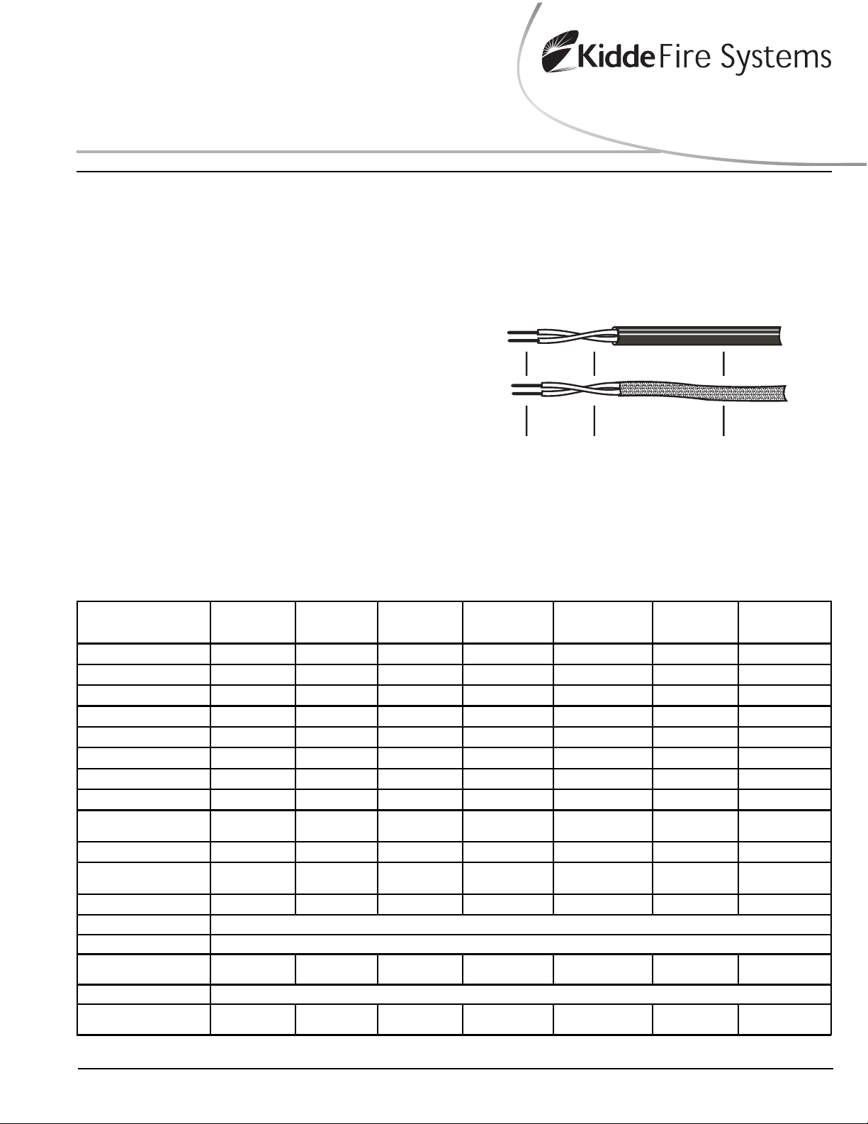
from a fire over its entire length. The sensor cable consists
of a twisted pair of 19 AWG copper coated steel conductors
covered by a temperature sensitive insulation, and protected
by either a plastic braid or jacket for various environmental
applications (see Figure 1).
LHS is designed for open area as well as proximity detection. A wide range of jackets and operating temperatures
(see Table 1) are available for proper system design, including confined areas or harsh environments which prohibit the use of other forms of detection. LHS cable is
compatible with any Fire Control Panel that is capable of
accepting contact closure type initiating devices.
The LHS linear heat detector is Factory Mutual Approved.
An FM Approved installation requires the LHS cable to be
connected to an FM Approved Fire Control Panel.
Effective: June 2006
OPERATION
The heat from a fire causes the LHS cable’s special insulation to melt at a specific temperature, allowing the two conductors to short together, thus creating an alarm condition
on the Fire Control Panel. The LHS cable may also be used
as a stand-alone contact device. The LHS normal operating state is an open circuit.
Conductor
Tinned
copper-covered
steel
Insulation
Temperature-sensitive
thermoplastic or
fluoropolymer
Figure 1. Cable Construction
Jacket
Thermoplastic strip
braid, PVC, nylon, or
fluoropolymer
Table 1. LHS Sensor Cable Specification
Part Number:
656 ft (200 m) length roll
3,280 ft (1000 m) length roll
Alarm Temperature
Ambient Storage Te mp. *
Min. Installatio n Temp.
Min. Operating Temp. **
Application
Approved Spacing
Flame Detection
Outer Jacket Materia l
Outer Jacket Color
Conductor Insulation
Conductor Color
External Diameter
Electrical Rating
Conductor Resistance
Conductor Capacitance
Insu la tio n Rat in g
Weight
* Do not store in direct sunlight. ** When not subjected to vibration.
73-200000-001
73-201000-001
155°F (68° C) 155°F (68° C) 185°F (8 5°C) 185°F (85 °C ) 220°F (105° C) 350°F (17 6° C) 465° F (24 0° C)
Up to 113°F (45° C) Up to 113°F (45° C) Up to 113° F (45° C) Up to 113°F (45° C) Up to 158° F (70° C) Up to 221° F (105° C) Up to 39 2° F (200° C)
5°F (-15° C) 5°F (-15° C) 5°F (-15°C) 5°F (-15° C) 32°F (0° C) 32°F (0° C) -4°F (-2 0°C)
-40°F (-40° C) -40°F (-40°C) -40°F (-40°C) -40°F (-40° C) -22°F (-30° C) -40°F (-40° C) -58° F (-50° C)
Indoor Only Indoor/Outdoor Indoor Only Indoor/Outdoor Indoor/Outdoor Indoor/Outdoor Indoor/Outdoor
20 ft. (6 m) maximum 20 ft. (6 m) maximum 20 ft. (6 m) maximum 20 ft. (6 m) maximum 20 ft. (6 m) maximum Proximity Detection Proximity Detectio n
5 seconds (max) 5 seconds (max) 5 seconds (max) 5 seconds (max ) 12 seconds (max) 20 seconds (max) 20 seconds (max)
Polypropylene Braid Nylon Polypropylene Braid Nylon PVC PVC FEP
Red/Green Tracer
EVA EVA EVA EVA Polythene Polypropylene FEP
1 Black
1 Red
0.146 in ch (3. 7 mm) 0.132 inc h (3. 35 mm) 0.146 inc h (3.7 m m) 0.132 inch (3. 35 mm) 0.1 67 inc h (4.25 m m) 0. 171 inc h (4. 35 mm) 0.138 in ch (3.5 mm)
20.2 1 pF/ft.
(66.32 pF/m)
11.29 lb./1000 ft.
(16.8 kg/km)
73-200000-011
73-201000-011
Black
Marke d H804 0N
1 Black
1 Red
20.21 pF/ft.
(66.32 pF/m)
10.65 lb./1000 ft.
(15.85 kg/km)
1000 megohm per 3280 ft. (1000 m) afte r 1 minute @ 500 Vdc Minimum
73-200000-002
73-201000-002
Red /B lac k Trace r
1 Blac k
1 Red
30.48 ohms/1000 ft. @ 68°F (1 0 0 o hms/1 0 0 0 m) @ 2 0 °C
25.42 pF/ft.
(83.41 pF/m)
11.29 lb./1000 ft.
(16.8 kg/km)
73-200000-012
73-201000-012
Black
Marke d H8045N
1 Blac k
1 Red
1 Amp maximum, 110 Vdc maximum
25.4 2 p F /ft.
(83.41 pF/m)
10.65 lb./10 00 ft.
(15.85 kg/km)
73-200000-003
73-201000-003
19.9 6 pF/ft.
(65.48 pF/m)
15.25 lb./1 000 ft.
(22.7 kg/km)
Black Red White
1 Blac k
1 Red
73-200000-004
73-201000-004
1 Black
1 Blac k /Whi te
17.52 pF/ft.
(57.48 pF/m)
12.67 lb./1000 ft.
(18.85 kg/km)
73-200000-005
73-201000-005
1 Black
1 White
19.22 pF/ft.
(63.07 pF/m)
14.65 lb./1000 ft.
(21.8 kg/km)
Page 2
DESIGN CONSIDERATIONS
The system design and installation must follow accepted
principles of fire protection engineering, as well as comply
with applicable codes and standards:
• NFPA-72, National Fire Alarm Code
• NEC 760, National Electric Code
• Any local installation requirements
• Requirements of the Authority Having Jurisdiction
(AHJ)
1. Selection of the appropriate part number for a specific
application must take into consideration the temperature of the hazard, the ambient temperature, and the
environment where the sensor is installed.
2. For open area protection, LHS must be mounted at the
ceiling, using the FM Approved spacing between p arallel runs. Distances from walls are half the spacing
shown. The thermal path to the LHS sensor must not
be obstructed. Maintain a 1” (25 mm) distance from the
ceiling for fastest detection.
3. For proximity detection, the LHS sensor must be tight
against the object being protected, to insure good thermal transfer. Exercise care to insure that vibration and
sharp edges do not cause abrasions to the cable, which
could result in a false activation.
4. Outdoor applications may need to be shielded from direct sunlight to prevent the LHS sensor’s operating temperature and/or maximum ambient temperature from
being exceeded, which may cause a false activation.
5. To use LHS sensor in hazardous locations (Class 1
Groups A,B,C,D; and Class 2 Groups E,F,G), FM Approved intrinsic safety barriers must be used to isolate
the sensor from the control panel.
INITIA TING CIRCUIT WIRING
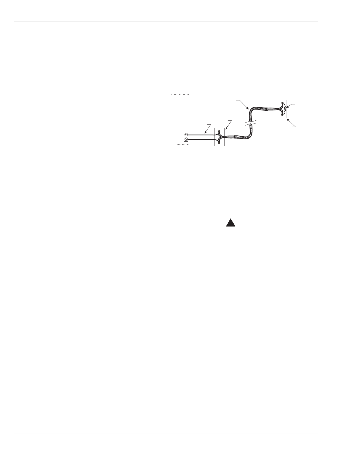
The LHS sensor connects to any Fire Control Panel (FCP)
as a dry-contact initiating device. Follow the installation instructions of the FCP for specific electrical requirements of
the initiating circuit (see figure 2).
1. The LHS sensor can be run as a Class B or Class A
circuit loop, with no T -t ap s.
2. The maximum LHS sensor zone length is determined
by the electrical characteristics of the FCP initiating circuit. Use the LHS resistance and capacitance as shown
in Table 1 to calculate the maximum length. For example, a FCP with input loop resistance of 50 ohms will
allow 820 feet (=50/(2 x 0.03048)) of LHS sensor.
3. If the FCP is some distance away from the protected
space, install LHS sensor only in the protected space,
and use lead-in cable to connect the LHS sensor to the
FCP. The lead-in cable can be any copper wiring approved for fire alarm use.
4. The LHS sensor in the protected space does not need
to be contiguous. Copper wiring approved for fire alarm
use may be used to connect the separate lengths of
LHS sensor.
5. If the initiating circuit is run as Class B (2 wire), then an
end-of-line device compatible with the FCP must be
installed at the end of the LHS sensor cable.
6. If allowed by the AHJ, other initiating devices (smoke
detectors, manual stations, etc.) may be installed on
the same zone as the LHS sensor. The LHS sensor
cable can be wired directly between these other devices.
Fire
Control
Panel
Initiating
Circuit
Lead-In
Cable
LHS Sensor
Cable
Junction
Box
End-of-Line
Device
Junction
Box
Figure 2. FCP with LHS Sensor Cable
SENSOR CABLE MOUNTING
The LHS sensor cable must be mounted in a professional
manner, in accordance with any applicable codes and requirements. The recommended mounting techniques described below do not preclude the use of alternate means
that are more suitable for a specific installation so long as
such means are acceptable to the local AHJ.
CAUTION
!
Where subject to mechanical damage, the
sensor cable should be protected to prevent
damage which could result in false activation.
> When designing the LHS layout, sensor cables
should be located where they will not be subject
to physical damage.
> If metal fasteners are used, non-metallic
bushings must be used to prevent chafing or
crushing of the sensor cables.
1. The cable should be adequately supported to prevent
sagging. It is not necessary to tension the cable, however on straight runs it is recommended that the cable
is supported every 3 feet (1 m). Reduced spacing may
be employed to suit local codes or conditions such as
around corners and transition points. Tension on the
sensor cable cannot exceed 50 Newtons. The sensor
cable can be bent around a radius no smaller than 2”
(50 mm)
2. Wherever possible, the sensor cable should be installed
in a continuous run with as few splices as possible.
3. The sensor cable should be the last item installed on a
project. If not installed last, it should be temporarily supported by cable ties to minimize the risk of damage.
Care should be taken to prevent damage due to foot
traffic, mechanical impact, kinking or any external heat
sources.
2
Page 3

4. Weather-Tight Connector, P/N 73-117068-027 is used
CAUTION
!
to provide appropriate strain-relief where the sensor
cable enters an electrical box or enclosure. It is recommended to secure tension on the end of a long sensor
cable run. The connector is designed to thread into a
standard 3/4" cast electrical box opening (3/4” NPT).
Nylon
Cable
Clamp
Sensor Cable
Sensor
Cable
Figure 3. Weather-Tight Connector
5. The sensor cable should be protected from mechanical
damage in non-detecting exposed areas by running it
in electrical metallic tubing (EMT). The sensor cable
should also be run in short pieces of EMT where the
sensor cable must pass through walls or partitions. The
ends of the EMT must have non-metallic bushings to
prevent damage to the sensor cable.
6. Selection of the mounting hardware that best suits the
application will depend upon the equipment or support
structures in the area being protected. Environmental
conditions and the practicality of mounting the clips
needs to be taken into consideration. The sensor cable
should always be attached to a support that permits the
least amount of movement, without crushing the cable
insulation. Three types of standard mounting hardware
(master clamp, flange clamp, nylon cable tie) permit
safe, secure sensor cable installation in most
applications.
7. The Master Clamp, P/N 73-1 17068-022 (box of 100), is
a multi-purpose fastener that fits all beam flanges up to
½” (13 mm) thick and resists vibration. Use the Nylon
Cable Clamp, P/N 73-117068-025 (box of 100) to fasten the sensor cable to the master clamp.
Nylon Cable
Clamp
Sensor Cable
Figure 4. Master Clamp
8. The Flange Clip is available in two sizes. P/N 73-117068-
023 (box of 100) fits up to 3/16" (4 mm) thick metal.
P/N 73-117068-024 (box of 100) fits 3/16" (4 mm) to ¼”
(6 mm) thick metal. They are easily hammered onto
metal flanges on roof trusses and shelving for secure
mounting which resists vibration. Use the Nylon Cable
Clamp, P/N 73-117068-025 (box of 100) to fasten the
sensor cable to both sizes of flange clips.
Figure 5. Flange Clip
9. The Nylon Cable Tie, P/N 73-117068-020 (box of 100),
is a heavy duty mounting tab cable tie that is strapped
to sprinkler or other fire protection pipes up to 8" (20
cm) in diameter. This method of mounting the LHS
sensor may be used if acceptable to the local AHJ. Use
the Nylon Cable Clamp, P/N 73-117068-025 (box of 100)
to fasten the sensor cable to nylon cable tie.
Pipe
Nylon Cable
Tie
Nylon Cable
Clamp
Sensor Cable
Figure 6. Nylon Cable Tie
When the LHS sensor cable is installed in below
freezing environments, special precautions
should be taken to avoid contact with or
movement of the sensor cable. At temperatures
below 32OF (0OC), the Nylon Cable Tie may break
as a result of jarring or physical contact.
10. Messenger cable must be used if the LHS sensor cable
needs to be suspended for some distance over an object
or an area, without a ceiling to attach the cable to. Commercially available stainless steel cable of a suitable size
should be used as messenger cable, tensioned appropriately . The sensor cable can be attached to the messenger
cable using cable ties, approximately every 3 feet (1 m).
SENSOR CABLE SPLICING
The LHS sensor cable must be spliced or electrically connected in a professional manner, in accordance with any
applicable codes or requirements. The recommended splicing techniques described below do not preclude the use of
alternate means that are more suitable for a specific installation. Because of the heat-sensitive nature of the sensor
cable insulation, soldering or heat-shrink tubing should never
be used when splicing LHS sensor cable.
Preferred Method - Using a junction box:
The preferred method for joining two lengths of sensor cable,
or for connecting sensor cable to copper lead-in wire, inter-
3
Page 4
-
h
.
-
L
connecting cable, or an end-of-line device, is to make the
connection inside a junction box.
1. The sensor cable can be joined using any industry standard method for connecting copper conductors. Positive, compression type connectors must be used, such
as wire nuts (3M/Highland H-30 or equal), butt splices
(Panduit BSN18 or equal), or a 2-position terminal block
(Molex/Beau C1502-151 or equal), following the
manufacturer’s installation instructions.
2. Any standard electrical junction box with a cover may
be used. In wet or damp locations, a waterproof box
must be used. The P/N 73-117068-027 Weather-Tight
Connector (or equivalent) must be used to provide strain
relief on the sensor cable where it enters the box. Do
not use “Romex” style cable clamps, as they may crush
the cable, possibly causing a false alarm.
Alternate Method – In-line Splice:
Where permitted by the AHJ, in-line splicing of two lengths
of sensor cable may be permitted. In-line splicing is not recommended for connecting sensor cable to copper lead-in
wire, interconnecting cable, or an end-of-line device. In-line
splicing is also not recommended if the sensor cable is under any significant tension.
When used for proximity detection, loop the sensor cable,
as the splice area does not provide detection coverage.
1. The sensor cable must be joined using nylon insulated
compression butt splices (Panduit BSN18 or equal).
Offset the two butt splices from each other.
2. Strip the jacket and insulation from each cable as shown
in figure 7.Trim the two conductors with the offset as
shown.
1 1/4” (30 mm)
1/4” (6.4 mm)
1/4” (6.4 mm)
4” (100 mm)
Figure 7. Strip the Sensor Cable
3. Crimp on the two butt splices as shown in figure 8, using an approved crimp tool (Panduit CT-1550 or equal).
Butt Splice
Figure 8. Crimp the Sensor Cable
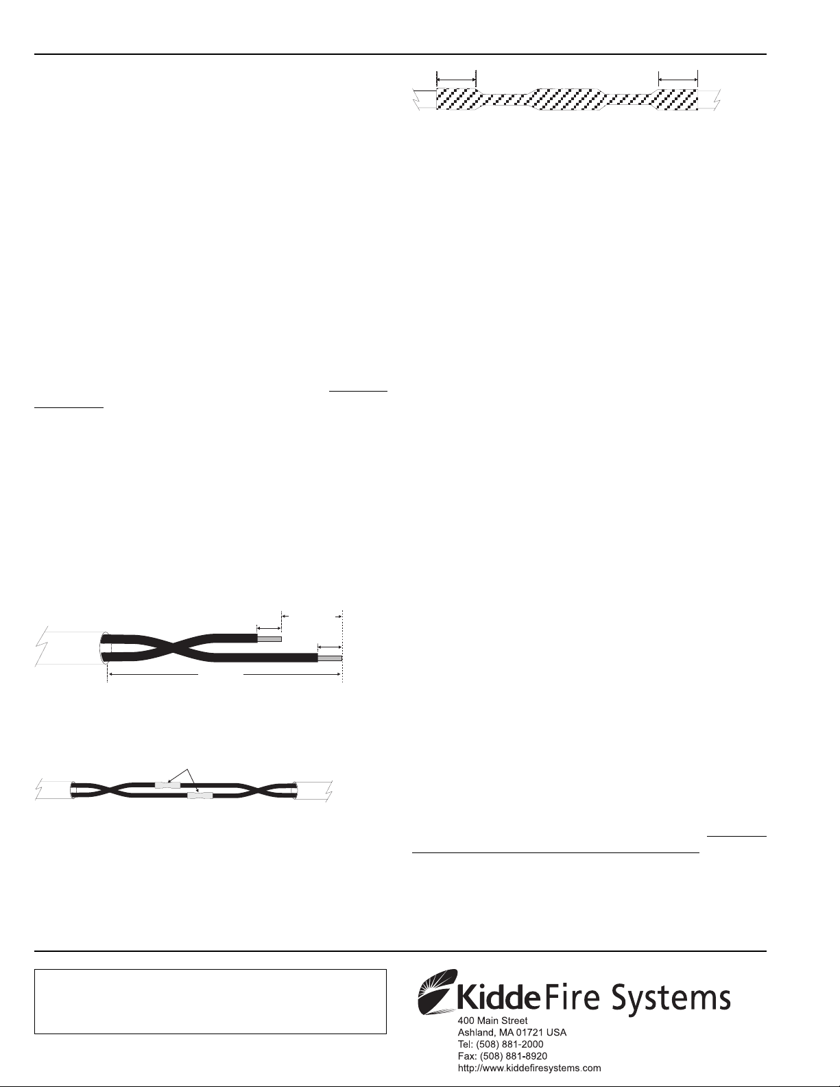
4. For dry locations, seal the splice by wrapping electrical
tape (3M/Scotch Super 33+ or equal) around the splice,
following the manufacturer’s instructions. Stretch and
overlap each turn of the tape by about 1/2 its width. The
tape should extend 2” (50 mm) beyond the ends where
the sensor cable jacket was cut. See figure 9.
2” (50mm)2” (50mm)2” (50mm)2” (50mm) 2” (50mm)2” (50mm)
Wrap over
Butt Splice
Figure 9. Seal the Splice
5. For damp or wet locations, seal the splice by wrapping
silicon fusion tape (Tyco Electronics/Amp 608036-1 or
equal) around the splice, following the manufacturer’s
instructions. The tape should extend 2” (50 mm) beyond the ends where the sensor cable jacket was cut.
See figure 9.
TESTING
Functional testing of the LHS sensor cable should follow
the guidelines for fixed-temperature non-restorable line type
heat detectors in Chapter 7 of NFP A-72, National Fire Alarm
Code. Consult with the AHJ for additional testing requirements that may apply to your specific installation. Functional
testing verifies the electrical operation of the sensor cable
and does not require a heat source.
1. Place a short across the end-of-line (EOL) device for
an LHS zone, and verify that the zone goes into alarm.
2. (If required by the AHJ) Remove one leg of the EOL for
an LHS zone, and verify that the zone goes into trouble.
3. (If required by the AHJ) Disconnect both conductors of
the LHS zone from the FCP. Place a short across the
EOL. At the FCP end of the zone, measure and record
the total loop resistance of the sensor cable. Compare
it to the acceptance test value.
MAINTENANCE
The LHS sensor cable requires no maintenance, other than
visual inspection to insure the integrity of the installation.
Damage To The Sensor Cable:
If the sensor cable is physically damaged, the conductors
may short together, causing an alarm. Locate the short circuit by visual inspection, by using an ohmmeter (comparing
to the value obtained during the acceptance test), or by using a tone generator & probe set. Splice in a new piece of
sensor cable. Replace at least 3 ft. (1 m) of the sensor cable
on both sides of the damaged piece.
After A Fire Event:
As the LHS sensor cable is non-restoring, it must be replaced after detecting a fire. If the entire zone is not being
replaced, splice in a new piece of sensor cable, extending
at least 10 ft. (3 m) beyond the affected section.
LHS is a trademark of Kidde-Fenwal, Inc.
These instructions do not purport to cover all the details or variations in the equipment de
scribed, nor do they provide for every possible contingency to be met in connection wit
installation, operation and maintenance. All specifications subject to change without notice
Should furhter information be desired or should particular problems arise which are not cov
ered sufficiently for the purchaser’s purposes, the matter should be referred to KIDDE-FENWA
INC., Ashland, MA 01721. Telephone: (508) 881-2000
06-236279-003 Rev AC ©2006 Kidde-Fenwal Inc. Printed in U.S.A.
 Loading...