

Page 1
Kidde Engineered Fire
Suppression System
Designed for use with 3M™ Novec 1230™ Fire Protection Fluid
Explosion Proof Solenoid,
Electric Control Head Data Sheet
FEATURES
• Explosion Proof:
– UL Listed as Suitable for Hazardous Locations
Class I Div 1 Groups C and D
Class II Div 1 Groups E, F and G
• FM Approved
• Compatible with UL Listed and FM Approved
Suppression Systems:
®
– FM-200
– Carbon Dioxide Systems
–FE-13
Systems, Including the ADS
™
Systems
P/N: 81-100000-001
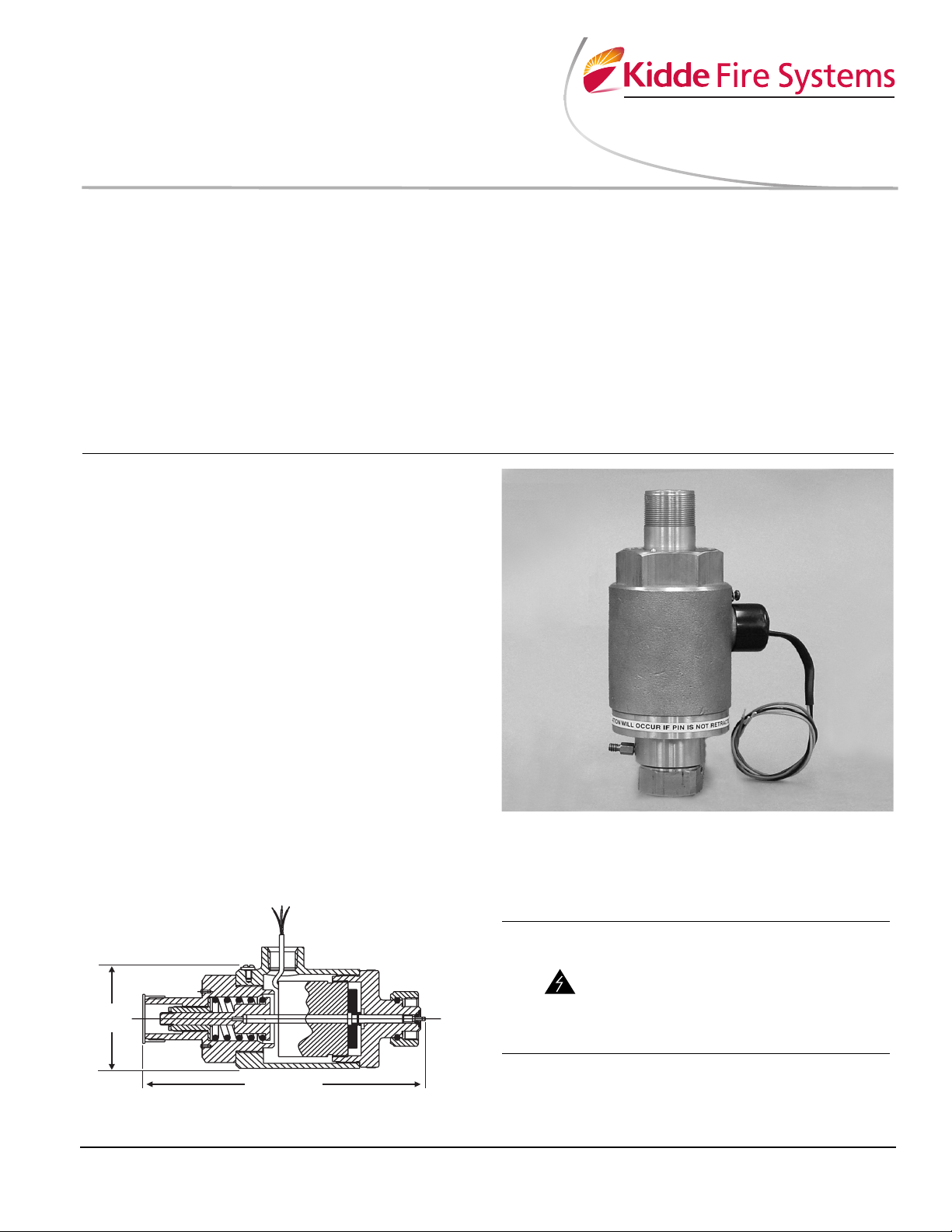
DESCRIPTION
The Explosion Proof Control Head is designed to operate
FM-200
valves, stop valves and directional valves. The Explosion
Proof Control Head can be operated electronically from
the Detection and Control system, or by local manual
operation via an affixed manual control head. The Explosion Proof Control Head has a continuous current draw,
which must be accommodated for at the Control Panel.
The actuating pin latches in the released position and
must be mechanically reset prior to re-arming the system.
A suitable Control Panel, Listed and/or Approved for use
with the Explosion Proof Control Head, shall be provided
for supervision of the releasing circuit per NFPA requirements.
®
, ADS, Carbon Dioxide and FE-13™ cylinder
•Operated By:
– Control Panel
– Mechanical Manual Actuator
• Nominal 24 Vdc Operation
• Low Current Consumption
• Operates:
– Cylinder Valves
–Stop Valves
– Directional Valves
• Wide Operating Temperature Range
• Rugged Brass Body
A UTC Fire & Security Company
Effective: April 2008
K-45-9049
The Explosion Proof Control Head is designed and rated
for use in the following hazardous areas: Class I Division
1 Group C and D and Class II Division 1 Group E, F and
G.
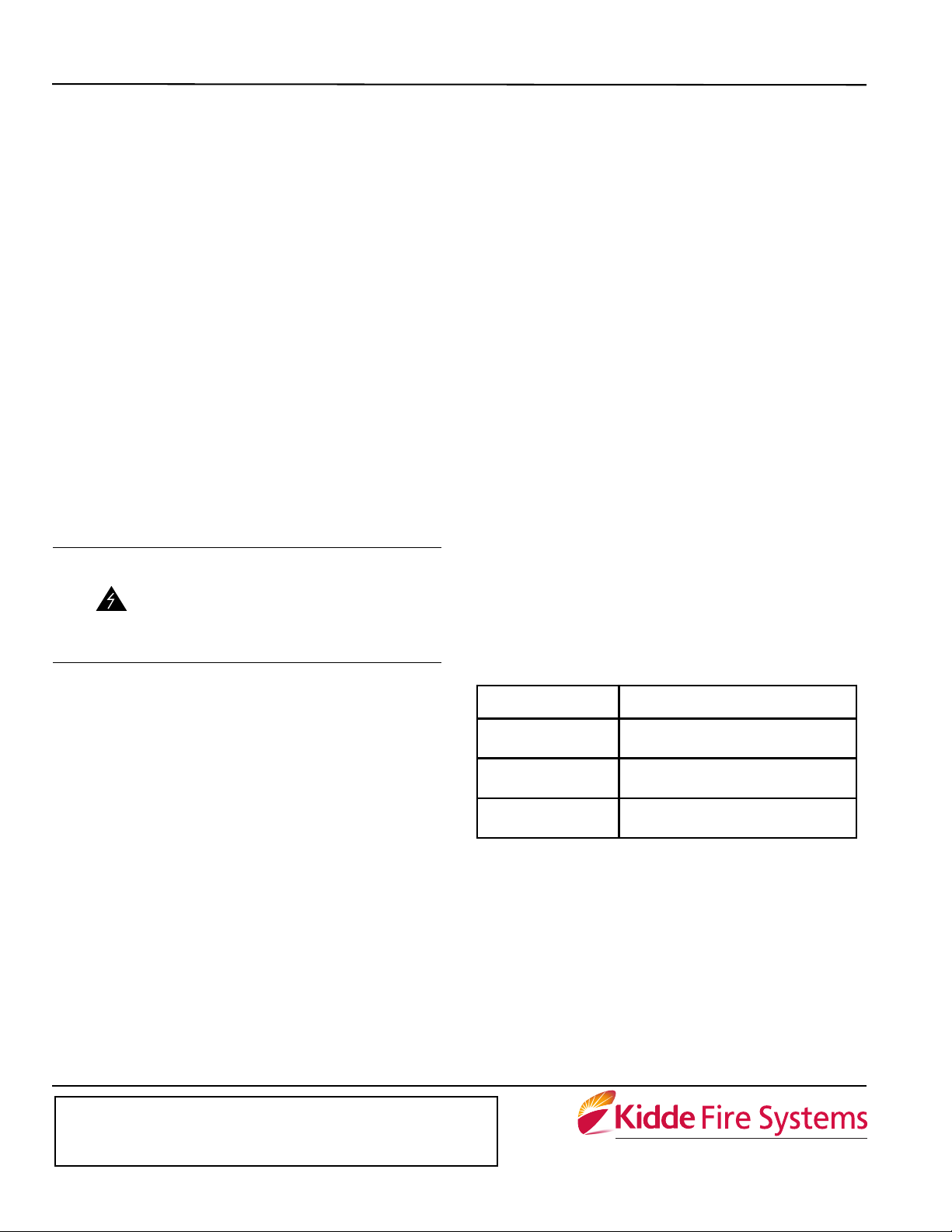
3.0 in.
(76 mm)
7.8 in. (198 mm)
Figure 1. Assembly Drawing
INSTALLATION
The Explosion Proof Control Head can be mounted
directly on either the cylinder valve, stop/directional
valve.
Care should be taken to ensure that
the actuating pin is in the set position
when attaching the control head to the
cylinder or the stop/directional valve.
WARNING
Tighten the swivel nut securely in place.
Accidental system discharge could
occur, which could cause property
damage, personal injury and/or death.
Page 2
When installing the Explosion Proof Control Head in hazardous locations, wiring connections must be terminated
in explosion proof junction boxes.
The lead wires must be connected using the indicated
polarity (red to positive, black to negative) in order to
obtain correct operation.
MAINTENANCE
Regular scheduled maintenance should be performed on
the Explosion Proof Control Head to ensure that the unit
operates correctly if and when required.
MONTHLY
The Explosion Proof Control Head should be inspected
for any signs of physical damage, deterioration, corrosion, distortion, cracks, dirt ingress and loose couplings.
Tighten any loose couplings. Replace damaged or missing caps. Replace control head if damage is found.
Ensure that all explosion proof control heads are in the
“set” position.
SEMI-ANNUALLY
The Explosion Proof Control Head should be tested for
proper operation.
All Explosion Proof Control Heads
should be removed from agent cylinders (Carbon Dioxide, FM-200 or FE-
WARNING
Remove control heads from all master cylinders within
the hazard area being tested. Let the Explosion Proof
Control Head hang freely from the flexible electrical conduit connections. Operate the Explosion Proof Control
Head, either by actuation at the system control panel or
via manual operation of an electric pull station. Ensure
that the control head has operated. Observe that the
actuating pin has moved to the fully released position. If
any control heads have not operated, check circuit for
electric continuity. Replace all damaged control heads.
Repeat operation test if any control heads have been
replaced. Replace any damaged control head, which fails
to reset properly. Make certain that electric control heads
are in the set position before reconnecting to agent cylinders. Reattach all control heads to threaded ports on cylinder valves and tighten swivel nuts securely.
13) to avoid accidental system discharge, which could cause property
damage, personal injury and/or death.
SPECIFICATIONS
Part Number: 81-100000-001
Applications: FM-200, ADS, Carbon Dioxide
and FE-13 Suppression Systems
Approval/Listing:
Releasing Device– UL, FM
HazLoc– UL, FM
HazLoc Ratings: Class I Division 1 Group C
and D
Class II Division 1 Group E, F
and G
Operating Voltage: 18 Vdc @ 0.20 A to
30 Vdc @ 0.50 A
Current Draw:
At 24 Vdc– 270 mA continuous
At 30 Vdc– 500 mA continuous
Wiring Connections:
Wire Size– 18 AWG
Lead Length– 36 in. (914 mm)
Ambient Temperature: -40°F to 130°F (-40°C to 55°C)
Construction:
Material– Brass body
Weight– 8.1 lb. (3.7 kg)
Dimensions: 3 in. D x 7.8 in. L
(76 mm D x 198 mm L)
ORDERING INFORMATION
Part Number Description
81-100000-001
870652 Mechanical Manual Actuator
81-129958-001 Reset Tool Assembly
Explosion Proof Solenoid
(Electric Control Head)
This literature is provided for informational purposes only. KIDDE-FENWAL, INC.
assumes no responsibility for the product’s suitability for a particular application. The
product must be properly applied to work correctly.
If you need more information on this product, or if you have a particular problem or question, contact KIDDE-FENWAL, INC., Ashland, MA 01721. Telephone: (508) 881-2000.
K-45-9049 Rev AC © 2008 Kidde-Fenwal Inc. Printed in USA
A UTC Fire & Security Company
400 Main Street
Ashland, MA 01721
Ph: 508.881.2000
Fax: 508.881.8920
www.kiddefiresystems.com
 Loading...