


HART XL

HART XL
INSTALLATION
OPERATION &
COMMISSIONING
MANUAL
MANUAL NO. TM0042

Installation, Operation and Maintenance Manual
FOREWORD
This manual is intended to clearly and accu rately reflect the High-Sensitivity Smoke Detector system with
the Modular Control Equipment. This manual is to be used by trained distributors only. This publication
describes the installation, operation and maintenance for the High-Sensitivity Smoke Detector system.
TERMS AND ABBREVIATIONS
AC/a.c.- Alternating Current
AH Amperes per Hour
CPU- Central Processing Unit
DC/d.c.- Direct Current
DIA- Diameter
ESC- Escape
ESP- Extended Sampling Point
FT- Feet or Foot
FT/S- Feet per Second
GND- Ground
HSSD®- High Sensitivity Smoke Detector
HVAC- Heat, Ventilation and Air-Conditioning
IIM- Intelligent Interface Module
ISOL- Isolate
Km Kilometre
LCD- Liquid Crystal Display
LED- Light Emitting Diode
mA- Milliamperes
mm Millimetres
m/s Metres per Second
PC- Personnel Computer
PCB Printed Circuit Board
P/N - Part Number
Sq. Ft.- Square Feet
TBA To Be Advised
VVolts
VAC- Voltage Alternating Current
VDC - Voltage Direct Current
VS.- Versus
%/m Percent Per Metr e
%/ft Percent per Feet
Issue 1 Page i
February 2001

Installation, Operation and Maintenance Manual
TABLE OF CONTENTS
Para Page
1 INTRODUCTION........................................................................................................................1-1
1.1 Features ................................................................................................................................1-1
2 SYSTEM FUNCTIONAL DESCRIPTION...................................................................................2-1
2.1 General..................................................................................................................................2-1
2.2 Overall Functional Description ..............................................................................................2-1
2.3 Detector.................................................................................................................................2-5
2.3.1 Detector Head ..................................................................................................................2-7
2.3.2 Termination Board............................................................................................................2-9
2.3.3 Fan Module ....................................................................................................................2-11
2.4 Display Module....................................................................................................................2-11
2.5 Intelligent Interface Module.................................................................................................2-12
2.5.1 PC Port...........................................................................................................................2-13
2.5.2 RS-485 Connection........................................................................................................2-13
2.5.3 Telephone Port (with optional modem) ..........................................................................2-13
2.6 Power Su pplies ..............................................................................................................2-14
2.6.1 Self Contained Power Supply ........................................................................................2-14
2.6.2 Battery Calculation .........................................................................................................2-14
2.7 Use of the Elutriator.............................................................................................................2-16
3 CONTROLS AND INDICATORS................................................................................................3-1
3.1 Status Indicator......................................................................................................................3-1
3.2 Termination Board Indicator..................................................................................................3-1
3.3 Display Module......................................................................................................................3-1
3.4 Sounder.................................................................................................................................3-6
3.5 LaserNET Software...............................................................................................................3-7
4 INSTALLATION..........................................................................................................................4-1
4.1 Introduction............................................................................................................................4-1
4.2 Locating the Detector ............................................................................................................4-1
4.3 Installing the Detector............................................................................................................4-2
4.4 Termination Board Field Wiring.............................................................................................4-5
4.5 Installing the Display Module.................................................................................................4-6
4.5.1 Installing the Remote Display Module..............................................................................4-7
4.6 Installing Self Contained Power Supply ................................................................................4-9
4.7 Installing the Intelligent Interface Module............................................................................4-12
4.7.1 Wiring the RS-485 Network............................................................................................4-12
4.7.2 Installing the Stand Alone Intelligent Interface Module.................................................4-12
4.7.3 Setting Detector Address ...............................................................................................4-16
4.7.4 Installation Checks .........................................................................................................4-17
4.7.5 Installing Telephone Line to the Intelligent Interface Module.........................................4-17
4.7.6 Software Configuration...................................................................................................4-17
4.8 Programming.......................................................................................................................4-17
4.9 Installation Method for the Elutriator....................................................................................4-17
Page ii Issue 1
February 2001

Installation, Operation and Maintenance Manual
TABLE OF CONTENTS (Continued)
Para Page
5 SYSTEM DESIGN ......................................................................................................................5-1
5.1 Introduction ............................................................................................................................5-1
5.2 Selecting the Correct Detector...............................................................................................5-1
5.2.1 Ultra Detector....................................................................................................................5-1
5.2.2 Standard Detector.............................................................................................................5-2
5.3 Air Sampling Pipe Network Design........................................................................................5-2
5.4 Pipe Network Design Terms and Details...............................................................................5-2
5.5 Air Velocity.............................................................................................................................5-3
5.6 Branch Point ..........................................................................................................................5-3
5.7 Elutriator.................................................................................................................. ...............5-3
5.8 Elbow, Standard 90 degree ...................................................................................................5-3
5.9 Sweep Elbow......................................................................................................................... 5-3
5.9.1 Equivalent Feet.................................................................................................................5-4
5.9.2 Extended Sampling Point (ESP).......................................................................................5-4
5.9.3 Sampling Point (SP) .........................................................................................................5-4
5.10 Pipe Segment ........................................................................................................................5-4
5.11 Sampling Hole........................................................................................................................5-4
5.12 System Transport Time..........................................................................................................5-5
5.13 Suction Pressure ....................................................................................................................5-7
5.14 Zones of Varying Static Press ure ..........................................................................................5-7
5.15 Distributed Pipe Network Sampling -
Symmetrical and Non-Symmetrical Balanced Systems ........................................................5-7
5.16 Return Air Grill Sampling .......................................................................................................5-7
5.17 Return Air Duct Sampling ......................................................................................................5-7
5.18 Selecting a Sampling Method................................................................................................5-7
5.18.1 Telephone Central Offices................................................................................................5-8
5.18.2 Computer Rooms..............................................................................................................5-8
5.18.3 Clean Rooms....................................................................................................................5-8
5.18.4 Atriums..............................................................................................................................5-8
5.18.5 Office Areas......................................................................................................................5-8
5.18.6 Warehous e Stora ge..........................................................................................................5-8
5.19 Computer Balanced System Design using “SNIFF“ Version 3.0 Software............................5-9
5.19.1 Parameters for Computer Balanced Systems..................................................................5-9
5.20 Using the “SNIFF“ Version 3.0 Software ...............................................................................5-9
5.21 Return Air Duct Detection Design........................................................................................5-10
5.22 Sampling Pipe Requirements ..............................................................................................5-11
5.23 Return Air Grill Sampling Design.........................................................................................5-12
5.24 Installing the Air-Sampling Pipe Network.............................................................................5-13
5.25 Final touches........................................................................................................................5-14
5.25.1 Air-Samp li ng Pipe Labe ls ...............................................................................................5-14
5.25.2 Sample Port Labels ........................................................................................................5-14
5.25.3 Sample Point Labels.......................................................................................................5-14
5.25.4 Mini Sample Point Labels ...............................................................................................5-14
6 SYSTEM COMMISSIONING ......................................................................................................6-1
6.1 Introduction ............................................................................................................................6-1
6.2 System Checkout...................................................................................................................6-1
6.3 Monitoring and Testing Systems ...........................................................................................6-1
6.4 Transport-Time Testing..........................................................................................................6-2
6.4.1 Commissioning Sheet.......................................................................................................6-2
6.5 Suction Pressure Testing.......................................................................................................6-2
6.6 Gross Smoke Test .................................................................................................................6-3
6.6.1 Burning Wire Test.............................................................................................................6-3
Issue 1 Page iii
February 2001

Installation, Operation and Maintenance Manual
TABLE OF CONTENTS (Continued)
Para Page
7 ROUTINE MAINTENANCE ........................................................................................................7-1
7.1 Introduction............................................................................................................................7-1
7.2 Scheduled Maintenance........................................................................................................7-1
7.3 Maintenance Procedures ......................................................................................................7-1
7.3.1 Visual Check ....................................................................................................................7-1
7.3.2 Battery-Status Check .......................................................................................................7-1
7.3.3 Gross Smoke Test............................................................................................................7-1
7.3.4 Sampe-Hole Airflow Verificat ion Test...............................................................................7-2
7.3.5 Detector Sensitivity Test...................................................................................................7-2
7.3.6 Clean Detector .................................................................................................................7-2
7.3.7 Clean Elutriator.................................................................................................................7-3
8 TROUBLE SHOOTING AND CORRECTIVE MAINTENANCE..................................................8-1
8.1 Introduction............................................................................................................................8-1
8.2 Standard Fault Isolation Techniques.....................................................................................8-1
8.2.1 Visual Inspection ...................................................................................................................8-1
8.2.2 Power Checks .......................................................................................................................8-1
8.3 Troubleshooting.....................................................................................................................8-2
8.4 Replacement .........................................................................................................................8-8
8.4.1 Replacing the Detector.....................................................................................................8-8
8.4.2 Replacing the Detector Head...........................................................................................8-9
8.4.3 Replacing the Termination Board...................................................................................8-11
8.4.4 Replacing the Fan Module .............................................................................................8-14
8.4.5 Replacing the Display Module........................................................................................8-15
8.4.6 Replacing the Intelligent Interface Module.....................................................................8-17
8.4.7 Replacing the Single Zone Power Supply......................................................................8-17
9 PARTS LIST...............................................................................................................................9-1
APPENDIX...................................................................................................................................A1
LIST OF ILLUSTRATIONS
Figure Page
1.1
2.1
2.2 Typical System with Stand Alone Intelligent Interface Module...................................................2-4
2.3 Detector Block Diagram..............................................................................................................2-6
2.4 Detector Head Views..................................................................................................................2-8
2.5 Termination Board Internal Wiring Diagram.............................................................................2-10
2.6 Self Contained Power Supply Diagram....................................................................................2-15
2.7 Elutriator Cut-Away View..........................................................................................................2-16
4.1
4.2
4.3
4.4
4.5a Connecting the Internal Power Supply.....................................................................................4-10
4.5b Installing the Single Zone Power Supply..................................................................................4-11
4.6 Intelligent Interface Module Stand Alone Mounted (4-Wire) ....................................................4-14
4.7 Intelligent Interface Module Stand Alone Mounted (2-Wire) ....................................................4-15
Detector......................................................................................................................................1-3
Typical Stand Alone System.......................................................................................................2-3
Detector Installation Diagram.....................................................................................................4-4
Termination Board External Wirin g Diagra m..............................................................................4-5
Installing the Display Module......................................................................................................4-6
Installing the Remote Display Module........................................................................................4-8
Page iv Issue 1
February 2001

Installation, Operation and Maintenance Manual
LIST OF ILLUSTRATIONS (continued)
Figure Page
5.1 Anemometer................................................................................................................................5-3
5.2 Return Air Grill Sampling Method .............................................................................................5-12
5.3 Mini Sample Point Kit................................................................................................................5-13
6.1 Magnehelic Test Set-Up .............................................................................................................6-3
8.1 Paddle Lever...............................................................................................................................8-9
8.2 Replacing the Detector Head....................................................................................................8-10
8.3 Replacing the Termination Board .............................................................................................8-12
8.4 Termination Board Internal Wiring Diagram .............................................................................8-13
8.5 Replacing the Fan Module........................................................................................................8-14
8.6 Replacing the Display Module ..................................................................................................8-15
8.7 Replacing the Remote Display Module.....................................................................................8-16
8.8 Replacing the Single Zone Power Supply ................................................................................8-18
LIST OF TABLES
Table Page
1.1 Detector Technical Specifications...............................................................................................1-2
2.1 Detector Specifications ...............................................................................................................2-5
2.2 Display Module Specifications..................................................................................................2-12
2.3 Intelligent Interface Module Specifications ...............................................................................2-13
2.4 Self Contained Power Supply Assembly ..................................................................................2-14
4.1 Detector Address Switch Settings ............................................................................................4-16
5.1 Elbow Equivalent Measurements ...............................................................................................5-4
5.2 Minimum Detector Sensitivity Se tti ng .........................................................................................5-6
8.1 Troubleshooting Guide................................................................................................................8-2
8.2 Intelligent Interface Module to Computer Com mun ic at ions Faults.............................................8- 3
8.3 General System Faults ...............................................................................................................8-4
8.4 Intelligent Interface Module to Termination Board Communications Problems..........................8-5
8.5 Faults Indicated on the Display Module or LaserNET Graphic Display......................................8-6
Issue 1 Page v
February 2001

Installation, Operation and Maintenance Manual
SAFETY SUMMARY
Installation Precautions
reliability:
Several different sources of power can be connected to this High Sensitivity Smoke Detection system.
Disconnect all sources of power before servicing. The High Sensitivity Smoke Detector (HSSD) system and
associated equipment may be damaged by removing and/or inserting cards, modules, or interconnecting cables while
the unit is energised. Do not attempt to install, service, or operate this unit until this manual is read and understood.
Application of the system:
the HSSD system must be monitored before final commissioning. Special attention should be given to systems
installed where elevated levels of background ambient smoke or particulate concentrations are present within the
protected area. Examples of such applications would be: kitchens, boiler rooms, manufacturing or other processes
where open flames or unprotected heating surfaces are present.
This monitoring must be conducted for a minimum of two weeks and be conducted during all normal
situations which may cause an elevated level of smoke or particulate to occur in the protected area. This
monitoring process will determine the most appropriate detector sensitivity, alarm threshold and delay
settings for the application.
Use with fire suppression systems:
-
the release of a fire suppression system
should provide one initiation signal of a cross zo ned detection system.
Static Electricity:
-
When handling these components or modules, wear an antistatic wrist strap or grounding device.
Electronic components and modules can be damaged by small amounts of static electricity.
To reduce the possibility of inadvertent alarms caused by “normal” ambient conditions,
GENERAL SAFETY NOTICES
The following general safety notices supplement specific warnings and cautions appearing in the manual. The safety
precautions in this section must be underst ood and app lied during operation and maintenance.
Adherence to the following will aid in problem-free installation with long-term
Under no circumstances should the detector be used to directly initiate
. When used as detection for a fire suppression system, the detector
The following must be observed to maintain personnel safety.
TEST EQUIPMENT
Make certain test equipment is in good operating condition. Do not touch live equipment or personnel working on live
equipment while holding a test meter. Some types of measuring devices should not be grounded; these devices
should not be held when taking measurements.
FIRST AID
Any injury, no matter how slight, should never go unattended. Always obtain first aid or medical attention
immediately.
GENERAL PRECAUTIONS
The following general safety precautions are to be observed at all times:
1. All electrical components associated with equipment shall be installed and grounded in accordance with local
regulation requirements.
2. Special precautionary measures are essential to prevent applying power to equipment at any time maintenance
work is in progress.
3. Before working on electrical equipment, use a voltmeter to ensure that system is not energised.
4. When working near electricity, do not use metal rules, flashlights, metallic pencils, or any other objects having
exposed conductive material.
5. When connecting a meter to terminals for measurement, use range higher than expected voltage.
Page vi Issue 1
February 2001


Installation, Operation and Maintenance Manual
1 INTRODUCTION
This manual contains operation, installation, maintenance, trouble shooting and parts list information for
the High Sensitivity Smoke Detection (HSSD) system.
The HSSD system is designed to provide high sensitivity smoke detection for an area up to 2000 sq/m
(20,000 sq/ft). Detection of smoke is achieved by using a fan to draw air from the protected area through
sampling pipe network back to a Detector. The Detector will analyse the air for the presence of smoke.
The Detector uses laser based particle counting technology to achieve the highest levels of performance.
The unique design ensures that only smoke particles that pass through a focused laser beam are
detected. Consequently, the Detector’s performance will not be affected by the build up of dirt within the
detection head chamber. Therefore no filters are required and system maintenance is minim al.
Air is continuously sampled from risk areas along a pipe network to the Detector. The standard Detector
has a dynamic sensitivity range from 0.005%/m to 1%/m (0.0015% to 0.3%/ft) obscuration. Alternatively
an ultra Detector has an increased sensitivity range 0.001%/m to 0.1% to (0.0003% to 0.03%/ft) for use
in very clean applications. The Detector sensitivity can be set to accommodate varying background
levels.
A Display Module provides a visual indication of the system status, smoke level, alarm and trouble
conditions of the Detector. Software conditions in the Display Module are condition specific i.e. when the
system is in quiescent “Normal” is displayed with the company logo and time and date information.
Should an alarm or trouble condition be activated then the relevant condition will be displayed. The
Display Module can be fitted into the Detector or remotely mounted.
A termination board located within the Detector provides micro processor control of the HSSD system.
The termination board provides the inter fac e betw een the det ec tor head, the RS4 85 network, the Display
Module and the PC Port. An on board memory stores configuration details, history events and system
information.
1.1 Features
The following is a list of major features of the HSSD system.
Laser based particle counting technology.
No particle filters required.
Service port located on the side of the Detector to allow ease of commissioning.
Attachable 1 amp Self Contained Power Supply and battery back up unit.
On site sensitivity selection, to meet specific application requirements.
Four individual alarm levels (Pre-Alarm levels 1 and 2/Alarm levels 1 and 2).
Lasernet network options, 1 to 127 Detectors per system. Using RS485 communications.
Modular design for fast and easy servicing.
Smoke history and event log storage and battery back-up.
Issue 1 Page 1-1
February 2001

Installation, Operation and Maintenance Manual
Table 1.1 Detector Technical Specification
DESCRIPTION SPECIFICATION
Weight 3.4 kg (7.5 lbs)
Finish Polycarbonate Light Grey Material
Input Voltage 18 to 30 V DC (24 V DC nominal)
Standard Detector Ultra D etect or
Detector Sensitivity Range
Input Current (With Standard Head) 315 mA 345/445 mA *
Input Current (With Ultra Head) 395 mA 425/525 mA *
Operating Temperature
Operating Humidity (With Standard Head) 10 to 95% non condensing
Operating Humidity (With Ultra Head) TBA
Enclosure IP31
Dimensions 320 mm wide by 228 mm high by 108 mm deep
Alarm Relay(s) Normally open contacts, 2 Amp @ 28 V DC, resistive
Pre-Alarm Relay(s) Normally open contacts, 2 Amp @ 28 V DC, resistive
Isolate Relay Normally open contacts, 2 Amp @ 28 V DC, resistive
Trouble Relay Normally closed contacts, 2 Amp @ 28 V DC, resistive
Electrical Connection Up to 18 GA field wiring to removeable terminal blocks
Service Port Connection RJ12 – RS232 communications
Network Connection 2 pair – RS485 communications
Remote Display Connection RS485 communications ( 4 core including power)
Air Inlet Port 0.75 inch threaded
Exhaust Port 1 inch
0.005%/m to 1%/m
(0.0015% to 0.3%/ft)
Stand Alone With Display Module
0° to 52° C (32° to 125° F)
0.001%/m to 0.1%/m
(0.0003% to 0.03%/ft)
* Back-light off/Back-light on
Page 1-2 Issue 1
February 2001
Installation, Operation and Maintenance Manual
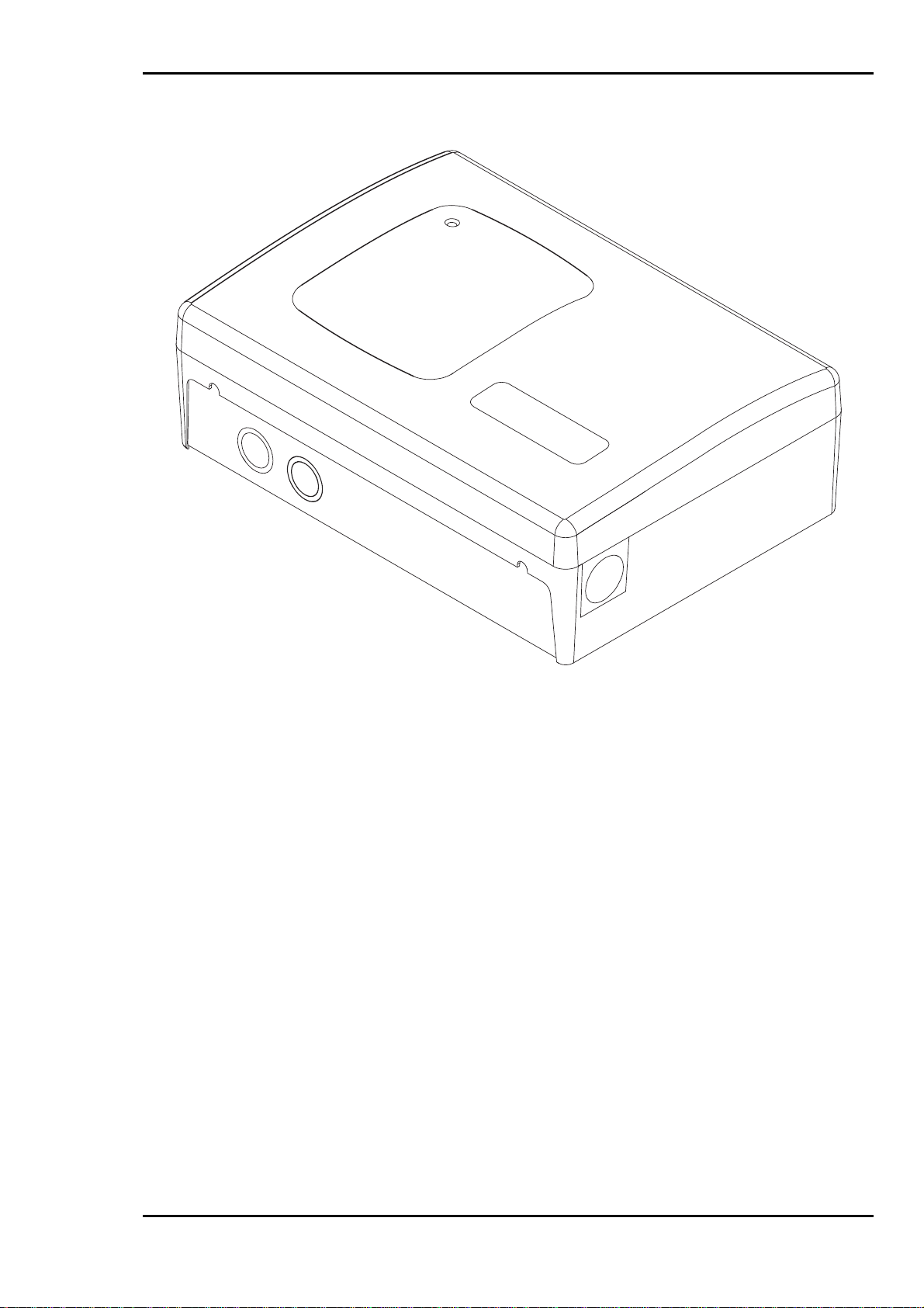
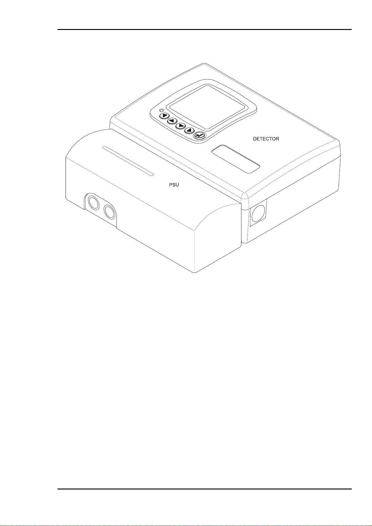
Figure 1.1 Detector
Issue 1 Page 1-3
February 2001

Installation, Operation and Maintenance Manual
This Page Intentionally Left Blank
Page 1-4 Issue 1
February 2001

Installation, Operation and Maintenance Manual
2 SYSTEM FUNCTIONAL DESCRIPTION
2.1 General
The following paragraphs pr ovide a functional description of the overall operation of the system, as well
as functional descriptions of the major components that together make up the High Sensitivity Smoke
Detection (HSSD) system.
2.2 Overall Functional Description
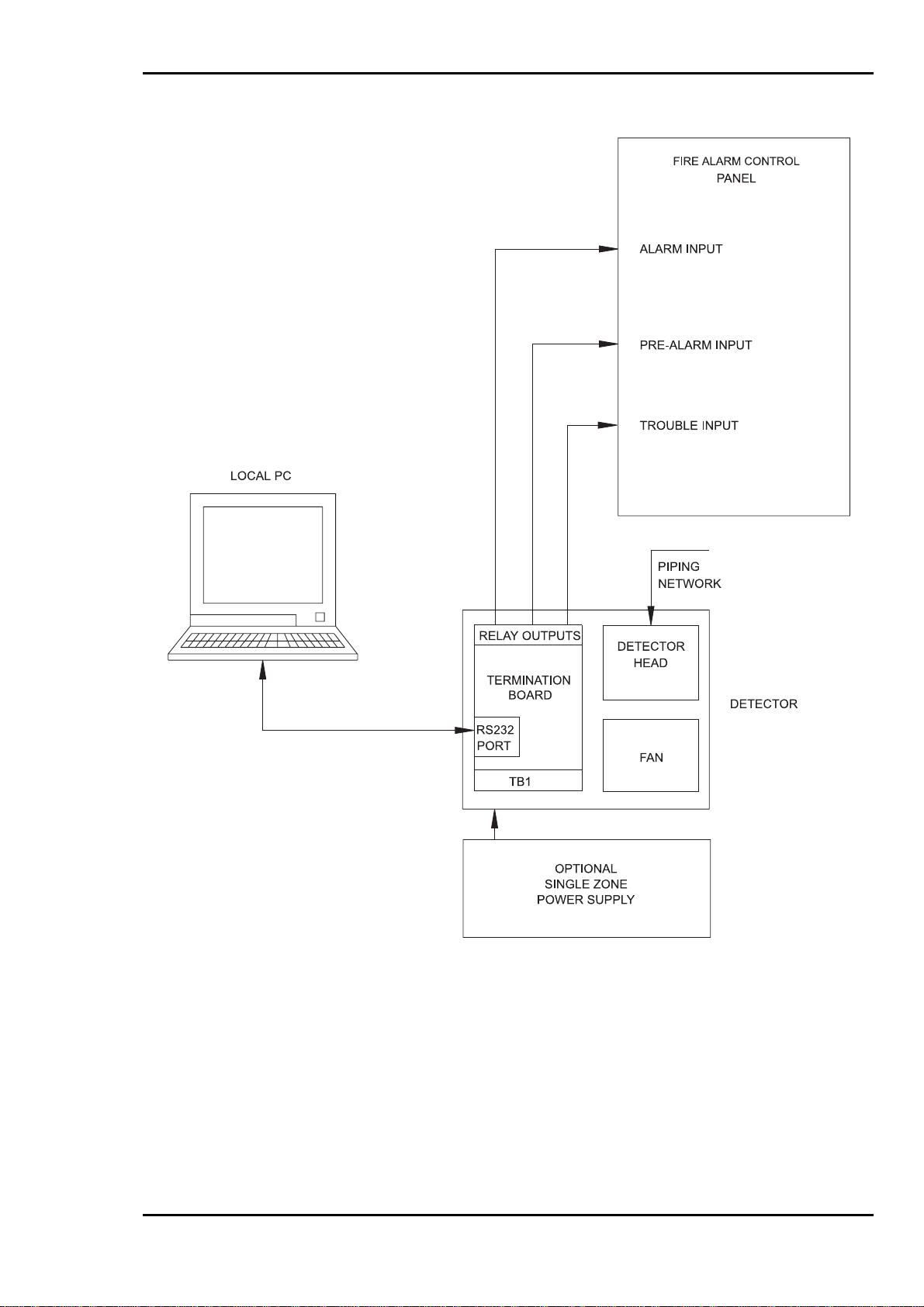
The High Sensitivity Smoke Detection system comprises a number of major components. Figures 2.1 to
2.2, show how these components are interconnected. These Figures also show the options available for
configuring the system depending on the application in which it i s to be used. The options available are
connecting the Detector via an Intelligent Interface. The system will support up to 127 Detectors. Each
Detector contains the following items:
termination board
detector head
fan module
Display module (optional)
This system is designed to provide high sensitivity smoke detection for an area up to 2000 sq-m (20,000
sq.ft). Smoke detection is accomplished by using a fan, mounted in the Detector, to draw in air from a
protected area through sampling pipe network back to the detector where the air is analysed for the
presence of smoke. The sensitivity of the Detector is programmable over a wide range to meet virtually
any application. In addition, an “Ultra” version of the detector is available with even higher sensitivity,
exclusively for clean room applications.
A three-colour light emitting diode (LED) mounted in the fascia plate of the Detector provides a visual
indication of the current status of the system. Current system conditions are indicated by this LED as
follows:
Continuous Green Normal
Flashing Green Auto Setup
Continuous Yellow Fault/Isolate
Flashing Red Pre-Alarm
Continuous Red Alarm
System status data collated on the termination board is transmitted via an RS-485 serial communications
link to the Display Module. The Display Module is an optional user interface which provides a display on
a back-lit mono LCD. The display provides a visual indication of the system status, smoke level, alarm
and trouble conditions of the Detector. By use of the control keys (4 cursor and 1 enter) an operator is
capable of viewing the information via a password protected menu function. The system status is also
indicated by a three colour LED providing the same functionality as described above.
Connections to a PC via an RS-232 network allow site-specific settings such as pre-alarm and alarm
levels to be loaded into a non-volatile RAM fitted on the termination board. The termination board
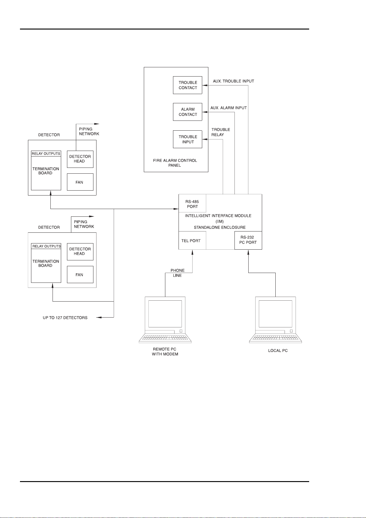
connects to the RS-485 network at an address set on a 7 way DIL switch. The Intelligent Interface
Module (IIM) is an optional user interface which serves as a communications controller, networking up to
127 termination boards. The IIM is linked via the RS-232 to a computer, running LaserNET version 3.0
software, situated on site. Alternatively, the IIM can be connected via a modem to a computer, which is
located at a remote site. Connection of the PC to the termination boards allows the system to be
configured and monitored from either a local or remote location. The IIM can also be programmed to dial
out to a remote PC should any alarm or trouble condition occur.
Issue 1 Page 2-1
February 2001

Installation, Operation and Maintenance Manual
In addition to the detector, a sampling pipe network is required to carry the sampled air from the protected
area to the detector. Overall perf ormance of the High Sensitivity Smoke Detection system is dependent
upon the layout of the air sampling pipe network. Use of the “SNIFF” computerised program balances the
piping network to provide for an equal intake of air at each sampling hole. For a detailed description on
how to design a pipe network reference should be made to the SNIFF Manual (Version 3.0).
The sampling pipe network is normally constructed from ½ inch, ¾ inch, or 1-inch internal-diameter
smooth bore pipe. The type of pipe is not critical because of the low operating pressures. Any smooth
bore pipe will be satisfactory provided it is rigid enough so that it does not sag between supports and it
meets all code requirements. Some commonly used types are PVC, ABS, CPVC, EMT and copper
tubing. Flexible tubing can be used for sampling hole drops.
Page 2-2 Issue 1
February 2001
Installation, Operation and Maintenance Manual
Figure 2.1 Typical Stand Alone System
Issue 1 Page 2-3
February 2001
Installation, Operation and Maintenance Manual
Figure 2.2 Typical System with Stand Alone Intelligent Interface Module
Page 2-4 Issue 1
February 2001

Installation, Operation and Maintenance Manual
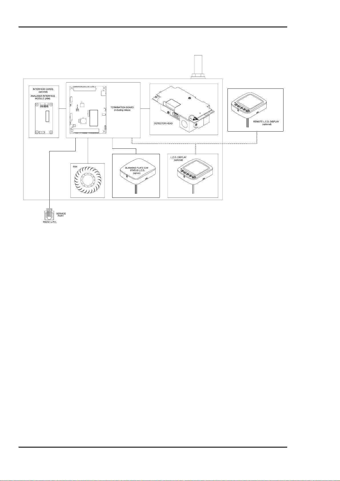
2.3 Detector
The Detector consists of a backbox with a removable cover, incorporated within the Detector are a
detector head, termination board and a fan. These three items are the major elements of the Detector,
refer to Figure 2.3 detailing the detector block diagram. The design of the Detector allows surface
mounting, thus providing ease of installation and maintenance. Replacement of any of the detector’s
main elements can be achieved without the need to remove the backbox, conduit, inlet or exhaust pipe.
The fan is mounted in a plenum within the Detector and is controlled via the termination board, thus
ensuring optimal fan speed. An LED located on the front panel of the Detector provides a visual
indication of the current system status. Two types of Detector are available; standard and ultra sensitive.
The ultra sensitive version is recommended for use in clean room applications only.
Table 2.1 Detector Specifications
DESCRIPTION SPECIFICATION
Part Number (With Standard Head) 53836-K183
Part Number(With Ultra Head) 53836-K186
Weight 3.4 kg (7.5 lbs)
Finish Polycarbonate Light Grey Material
Input Voltage 18 to 30 V DC (24 V DC nominal)
Stand Alone With Display Module
Input Current (With Standard Head) 315 mA 345/445 mA *
Input Current (With Ultra Head) 395 mA 425/525 mA *
Operating Temperature
Operating Humidity (With Standard Head) 10 to 95% non condensing
Operating Humidity (With Ultra Head) 10 to 70% non condensing
Alarm Relay Normally open contacts, 2 Amp @ 28 V DC, resistive
Pre-Alarm Relay Normally open contacts, 2 Amp @ 28 V DC, resistive
Isolate Relay Normally open contacts, 2 Amp @ 28 V DC, resistive
Trouble Relay Normally closed contacts, 2 Amp @ 28 V DC, resistive
Electrical Connection Up to 18 GA field wiring to removable terminal blocks
Service Port Connection RJ12 – RS232 communications
Network Connection 2 pair – RS485 communications
Remote Display Connection RS485 communications (4 core including power)
Air Inlet Port 0.75 inch threaded
Exhaust Port 1 inch
0° to 52° C (32° to 125° F)
* Back-light off/Back-light on
Issue 1 Page 2-5
February 2001
Installation, Operation and Maintenance Manual
Figure 2.3 Detector Block Diagram
Page 2-6 Issue 1
February 2001

Installation, Operation and Maintenance Manual
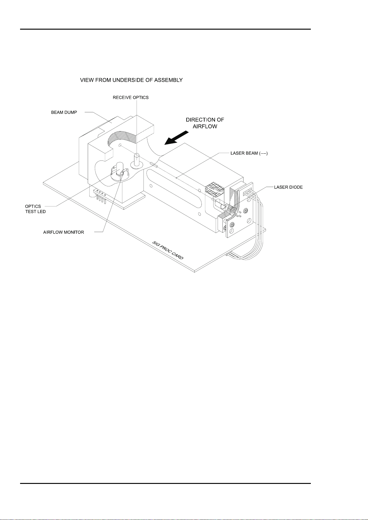
2.3.1 Detector Head
Located within the Detector, the detector head is a highly sensitive detector utilising a laser, focussed to a
narrow beam. The laser beam exits a sample chamber into an attached beam dump area which monitors
the laser intensity. A receive optics assembly is mounted on the sample chamber with its optical axis
normal to the laser beam axis (see Figure 2.4).
A particle-size discriminator inhibits the detector from responding to large particles, thus preventing
occasional large particles (dust, pollen, soot, etc.) from generating an alarm. As the smoke particulate
passes into the sampling element a sensor electronically counts each particle. Particle counting HSSD
devices are much more sensitive to the prevailing concentration of small particulate (the tell tale sign of
early combustion) than conventional devices. Although larger particulate such as dust does not
significantly affect the signal recorded (number of particles) from either a background or a prevailing
smoke environment. Most particulate with a diameter greater than 10Pm is electronically recognised and
thus not added to the smoke count register. This ensures a true and clear measurement of the absolute
real time concentration. Electronic circuitry within the detector head ensures that no change in sensitivity
occurs with changes in air flow. The Detector is calibrated so that it will not respond to particle sizes
smaller than 0.01 or greater than 10 microns. The intensity of the laser is monitored by a photocell. If the
intensity of the laser begins to vary from the factory set level, a feedback circuit automatically
compensates the laser drive circuit accordingly. This circuit arrangement virtually eliminates any change
in laser energy output which in turn keeps the detector sensitivity stable.
An airflow measuring circuit monitors the flow of air through the detector. Should the air flow vary or stop,
a status signal is transmitted to the termination board.
One of the features of the detector head signal processing that provides the dynamic sensitivity range.
The sensitivity range can be adjusted via LaserNET software to meet with system requirements. A
processor located on the signal processing board controls communications between the detector head
and the termination board. Information recorded by the detector head is continually communicated to the
termination board.
Two types of detector head are available; the standard detector head which has a dynamic sensitivity
range of 0.005% to 1%/m (0. 0015% to 0.3%/ft) and an ultra sensitive detector head specifically designed
for the clean-room applications. The ultra sensitive detector head incorporates an avalanche photon
detector and has a dynamic sensitivity range of 0.001% to 0.1%m (0.0003% to 0.03%/ft) for use in very
clean applications. Detector sensitivity can be programmed to accommodate varying background levels.
Issue 1 Page 2-7
February 2001
Installation, Operation and Maintenance Manual
Figure 2.4 Detector Head Views
Page 2-8 Issue 1
February 2001

Installation, Operation and Maintenance Manual
2.3.2 Termination Board
The termination board is micro processor controlled providing the interface between the detector head,
the RS-485 network, the Display module and the PC Port. A seven position DIP switch on the termination
board allows the network address to be set, enabling 127 Detectors to be connected. An on board
memory stores configuration details, history events and system information. In the event of a power
failure, information can be retained for up to a period of approximately 90 days by a battery back-up. An
on board LED, when lit, provides indication of power.
An adjustable switching regulator, located on the termination board, ensuring optimal supply voltage to
the fan.
The termination board provides 6 relays with volt free change-over contact rated at 2 amp, 30 V DC. Each
relay has its own operation as detailed below:
Pre-alarm level 1
Pre-alarm level 2
Alarm level 1
Alarm level 2
Trouble
Isolated
It should be noted that the Trouble relay is energised in its normal condition so it will transfer when power
is lost.
The termination board can communicate to an external PC, running LaserNET software, via an RS-232
output. Connection will be by a standard RJ12 connector. Communications will allow for the up/down
load of configuration and history data. Both configuration and history data are stored within an on board
non-volatile memory. The system will retain the configuration and history data following a CPU reset or
extended periods of power down only when the termination board battery link LK3 is installed.
The termination board provides connections for a supervised power supply unit, Intelligent Interface
Module (IIM) and a remotely mounted Display Module (optional). Ease of installation and maintenance is
achieved by using the removable terminals.
Issue 1 Page 2-9
February 2001
Installation, Operation and Maintenance Manual
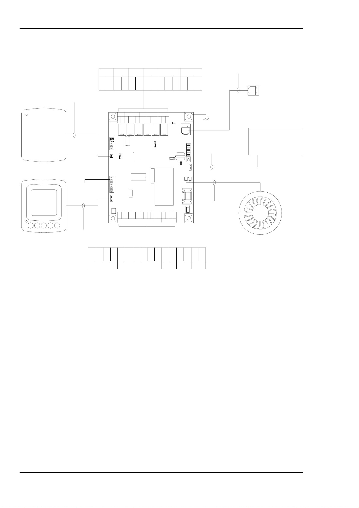
CABLE ASSEMBLY
TERM BOARD / TRI-COLOUR LED
BLANKING PLATE
C/W STATUSLED
FRONT PANEL OPTIONS
(LCD DISPLAY OR STATUS LED)
DISPLAY
MODULE
43682-K157
ANALASER
INTERFACEMODULE
(OPTIONAL)
CABLE ASSEMBLY
TERM BOARD / LCD DISPLAY
43682-K156
INTERNAL WIRING
PRE PREALARM1 ALARM2 ALARM 2ALARM 1 TROUBLE ISOLATE
CM CMNO NO CM NO CM NO NCCM NO CM NC NO
1
ALARM1
TROUBLE
CM NC NO
RL4
RL5
PROGRAM
LK2
P2
++++
PSU
STATUS POWER OUT
-
+
ISOLATE
POWERON
TB2
CM NC NO
LED
RL6
LK4
BAT1
REG1
TB1
1
---
POWERIN
+
--
-
-
++
PRE 2PRE ALARM2ALARM1ALARM
NO CM NO
CM NO CM NO
CM
1
RL1
RL2 RL3
P6
IC5
RELAYEXP/LOCALASER
LK1
P1
STATUSLED
P4
INTERFACE
P9
INTERNALDISPLAY
M/TERM
ON
1
SW2
HSSD
++
MAINLOOP
0V +24V
-
TERMINATION
CARD
P3
0V
IC9
IC7
+24V
EXTERNALDISPLAY
-
-+-
+
1
+
P5
LK3
P7
IC4
F2
-+
TB2
CHASSIS
GROUND
PC
CABLE ASSEMBLY
TERM BOARD / DETECTOR
43682-K155
MAINLOOP ADDRESS
SW1
DET.HEAD RESET
FAN AD J
FAN
1
CABLE SUPPLIED
F1
WITH FAN ASSEMBLY
TB1
1
+
CABLE ASSEMBLY
RJ12 / RJ12
43682-K158
RJ12 SOCKET
LOCATED ON LHS
OF UNIT
DETECTOR
H300/UHSSD
FAN
MAIN LOOP
PSU
STATUSEXTERNAL DISPLAY
POWER OUT
POWER IN
Figure 2.5 Termination Board Internal Wiring Diagram
Page 2-10 Issue 1
February 2001

Installation, Operation and Maintenance Manual
2.3.3 Fan M odule
The fan module contains a highly efficient radial fan that has been specifically designed for use within the
Detector. The fan draws air from the sampling pipe network through the detector head and then exhausts
the air through a port on the side of the unit or by an alternative optional rear exhaust port. In addition, an
adapter port returns the sampled air to the protected area. A regulated voltage is supplied to the fan
module from the termination board.
2.4 Display Module
The Display Module is an optional item that can be either mounted within the Detector or alternatively, it is
possible to mount remotely. Remote mount can be achieved by use of a back box or a rack mount
option. Maximum distance of up to 1 km from the Detector to the remote Display Module is allowed. In
either application, RS-485 communication and 28 V DC is supplied via terminals located upon the
termination board. Recommended cable type being Mineral Insulated Copper Cable (MICC).
Various facilities are provided by the Display Module that include the following:
Operator Visual Interface
Internal Audible Sounder alar m
Status LED
Control Keys (4 cursor and 1 enter)
The cursor control keys allow an operator to navigate through the displayed menu and password screens
by operating the Up, Down, Left or Right keys and the Enter key.
Real time system data is displayed which includes the current smoke level and airflow, all alarm
conditions, all trouble conditions and the current system status.
An internal sounder provides an audible indication that an alarm or trouble condition exists on the system.
If a trouble condition exists the sounder alarm operates intermittently. Upon the activation of an event the
sounder will provide an audible indication. The audible indication will continue until the operator silences
the sounder using the control keys.
The conditions that activate the sounder are:
Any Alarm Condition
Any Pre-Alarm Condition
Any Trouble Condition
A multi coloured LED that is controlled via the Display Module provides a visual indication of the current
system status.
Continuous Green Normal
Flashing Green Auto Setup
Continuous Yellow Fault/Isolate
Flashing Red Pre-Alarm
Continuous Red Alarm
Control keys are used to navigate through the menu selections.
Issue 1 Page 2-11
February 2001

Installation, Operation and Maintenance Manual
The Display Module incorporates a removable adapter plate, which permits the module to be mounted to
the wall.
Table 2.2 Display Module Specifications
DESCRIPTION SPECIFICATION
Part Number 53836-K182
Input Voltage 18 to 36 V DC (24 V DC nominal)
Maximum Input Current 30 mA (normal); 104 mA with Back-light ON
Operating Temperature 0° to 52° C (32° to 125° F)
Operating Humidity 10 to 95% non-condensing
2.5 Intelligent Interface Module
The Intelligent Interface Module (IIM) is an optional item, which can be mounted in a stand alone
enclosure. The IIM allows service and maintenance functions to be undertaken on the Detectors. The
IIM is a communications link networking up to 127 Detectors. A computer running LaserNET software
Version 3.0 can communicate with the IIM either with a local PC or remote PC connected by an optional
modem. This allows the Detectors to be completely configured and monitored from a central location with
the connection of an optional modem, allowing interrogation of the system with a remote PC.
The IIM stores all field-programmed parameters in non-volatile memory, thus ensuring that no
programming will be lost during a complete power failure. Field programmable parameters consist of the
following:
Three telephone numbers for auto-dial sequence
Twenty character owner location mess ag e
Installation engineer’s password
Owner’s password
Dial tone supervision enable/disable
FenwalNET interface port enab le/ dis ab le
AutoDial function enable and disable
Configuration of RS485 Network for style 6 or style 4
Trouble report delay
Security call back scheme enable/disable
Call back phone number
Page 2-12 Issue 1
February 2001

Installation, Operation and Maintenance Manual
2.5.1 PC Port
The PC Port is used for programming and may be used to provide ancillary on premises one way
communication of alarms and troubles to a PC (using LaserNET software).
2.5.2 RS485 Connection
Up to 127 Detectors can be connected via the RS-485 network with the maximum bus length of 1 kM
(4000 feet). This connection is capable of being wired for either Style 4 (Class B) or Style 6 (Class A)
supervised operation.
2.5.3 Telephone Port (with optional modem)
For a HSSD system using a PC running LaserNET software, located at a remote site, a telephone port on
the IIM allows off premises communication through a standard telephone line. The Telephone Port
provides communication via a modem and standard telephone line, and will provide ancillary off-premises
transmittal of Detector alarms and troubles.
Table 2.3 Intelligent Interface Module Specifications
DESCRIPTION SPECIFICATION
IIM with Modem Part Number 53836-K189
IIM without Modem Part Number 53836-K190
Input Voltage 20.4 V DC to 28 V (24 V DC Nominal)
Maximum Input Current
Operating Temperature 0° to 52° C (32° to 125° F)
Operating Humidity 10 – 95% non-condensing
70 mA (Max) Standby
80 mA (Max) Alarm
Issue 1 Page 2-13
February 2001

Installation, Operation and Maintenance Manual
2.6 Power Supplies
An optional self-contained assembly supplies power to a single HSSD system.
2.6.1 Self Contained Power Supply
The self contained power supply powers a single Detector, with or without a Display Module including 4
hours of battery backup.
Table 2.4 Self Contained Power Supply Assembly
DESCRIPTION SPECIFICATION
Part Number 53836-K185
Weight (including batteries) 3.1 kg (7 lbs)
Finish Polycarbonate Material Light Grey Cover with painted steel backbox
Input Voltage 90 to 260 V AC 50/60 Hz
Maximum Input Current 1 A
Operating Temperature
Operating Humidity 10 to 95% non condensing
Output Voltage 28.75 V DC
Output Current Maximum 1 A
Battery Charging Voltage 27.3 V DC
Battery Charge Circuit Fuses 500 mA
Trouble Relay Normally closed contacts, 1 Amp @ 28 V DC., resistive
Batteries Yuasa NP2-12 (12V 2.0 AH) x2
0°C to 52°C with no de-rating
2.6.2 Battery Calculation
The calculation used for determining the battery requirements for the Detector is detailed as follows:
Minimum Battery Capacity (Amps Per Hour) = 1.25 x ((S x A) + (1.75 x ((A + B)/2)))
Where S = standby period in hours.
A = quiescent current in amps.
B = alarm current in amps.
Page 2-14 Issue 1
February 2001
Installation, Operation and Maintenance Manual
Figure 2.6 Self Contained Power Supply Diagram
Issue 1 Page 2-15
February 2001
Installation, Operation and Maintenance Manual
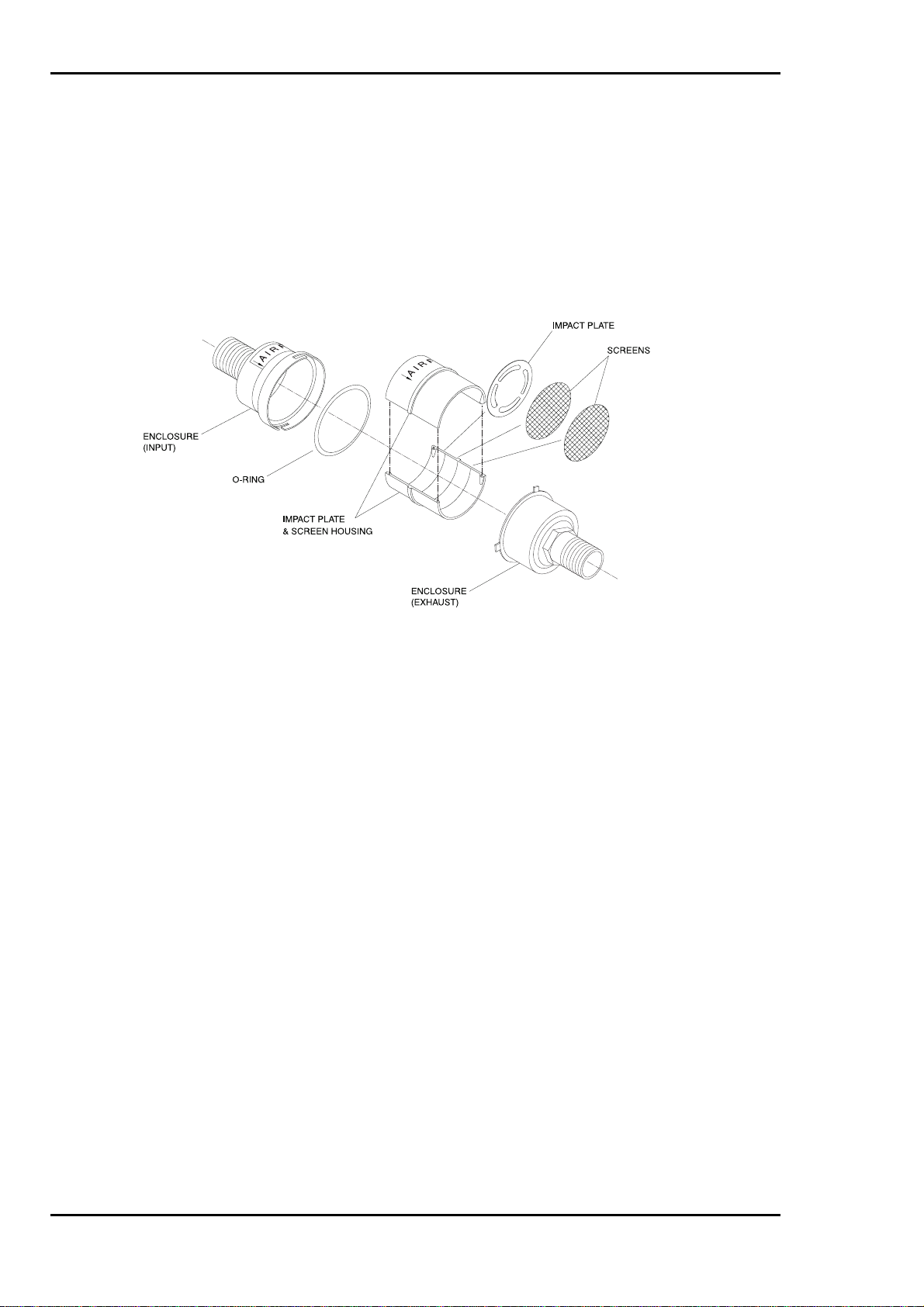
2.7 Use of the Elutriator
The Elutriator is an optional item and can be used if the protected area is expected to have heavy
amounts of non-combustion part icula te. An Elutr iator sho uld be inst al led to pr event bui ld- up of mat erial
within the Detector. The elutriator is an inertial particle separator that allows air to flow freely through it
while separating out large particulates by allowing them to accumulate on an impact plate. Refer to
Figure 2.8
Figure 2.7 Elutriator Cut-Away View
Page 2-16 Issue 1
February 2001

Installation, Operation and Maintenance Manual
3 CONTROLS AND INDICATORS
3.1 Status Indicator
A three-colour light emitting diode (LED) mounted in the fascia plate of the Detector provides a visual
indication of the current status of the system. A similar LED is also provided on the Display Module. The
LED changes colour to indicate the system status. System conditions that are indicated by this LED, are
as follows:
Continuous Green Normal
Flashing Green Auto Setup
Continuous Yellow Fault/Isolate
Flashing Red Pre-Alarm
Continuous Red Alarm
3.2
The termination board provides a Power On LED indicator. This is located in the top right corner of the
board and displays, when lit, that power is present.
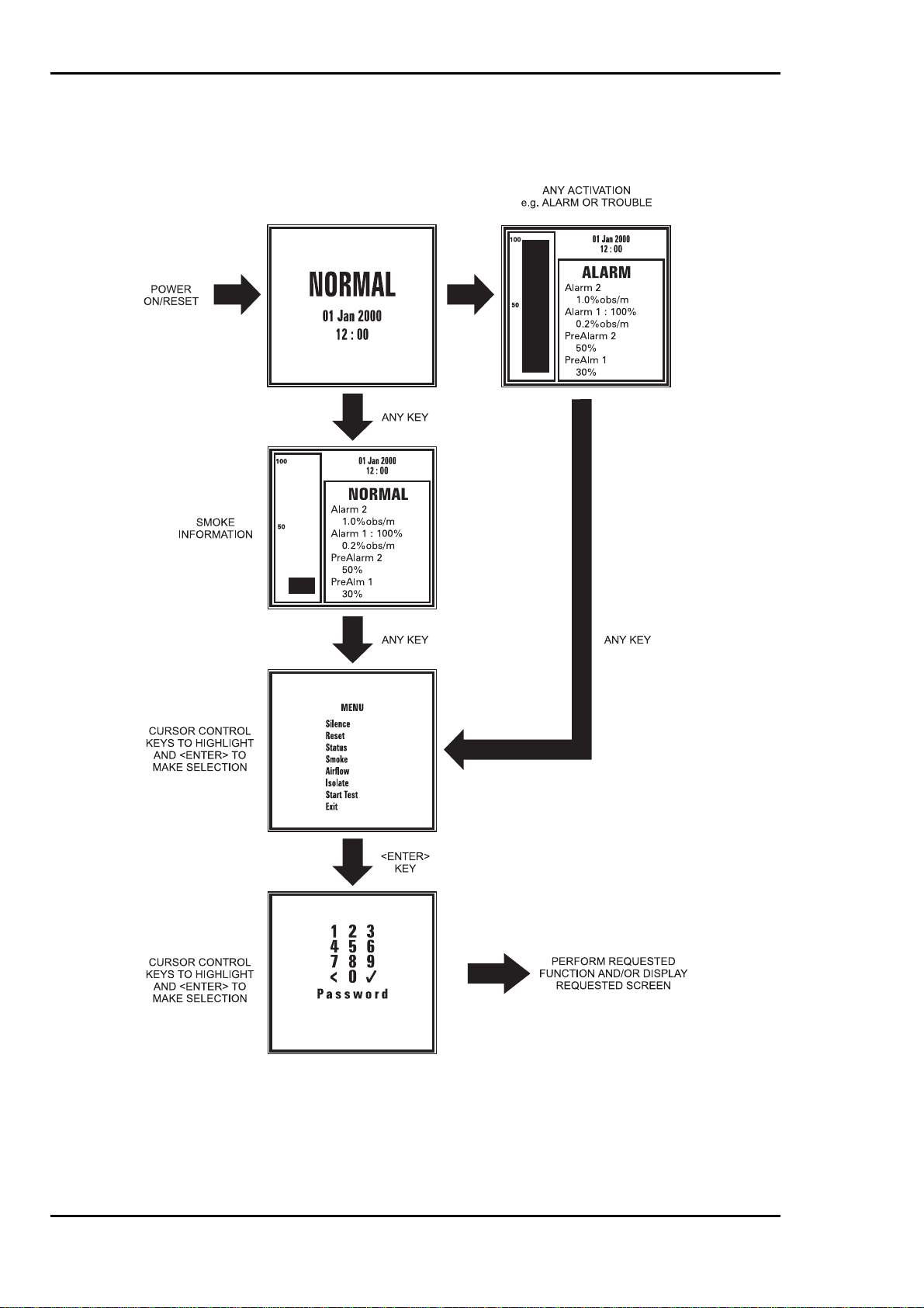
3.3 Display Module
The Display Module is an optional item, which provides a back-lit mono Liquid Crystal Display (LCD).
The main functi on is to provide a visual indication of the system status, these being smoke level, airflow,
alarm and trouble conditions of the Detector. The back-light of the Display Module operates upon
activation of any condition or by use of the control keys. If there are no further activations or operation of
any control key for one minute, the back-light will return to its normal state.
The Display Module allows an operator to request certain functions to be performed by selecting options
from a displayed menu list. The functions are as follows:
The above functions are available to an operator and are dependent upon the current status of the
system. Selected functions are only accessed provided a password is correctly entered.
Termination Board Indicator
Silence Cancels the internal audible sounder.
Reset Reset the Detector.
Status Allows viewing of the current status of the unit.
Smoke Allows viewing of Alarm sensitivity settings, Pre-Alarm settings and current
smoke levels.
Airflow Allows viewing of the airflow thresholds and settings.
Isolate Allows the Detector to be isolated and De-isolated.
Start Test Enables the Sensitivity Test of the detector head.
The following is an illustration showing the hierarchy of the display structure. Additionally the key presses
needed to access the required screen are also shown. Subsequent paragraphs in this part of the manual
provide detail information on each screen.
Issue 1 Page 3-1
February 2001
Installation, Operation and Maintenance Manual
Page 3-2 Issue 1
February 2001
 Loading...