

Page 1

HD135F
For model: HD135F
Heat Alarm User’s Guide
AC Wire-in Single and/or Multiple Station (up to 24 Devices) Heat Alarm
with 9 Volt Battery Back Up, 135ºF fixed temperature.
Thank you for purchasing this heat alarm. It is an important part of your family’s
home safety plan. You can trust this product to provide the highest quality safety protection. We know you expect nothing less when the lives of your family
are at stake. Kidde alarms and accessories CAN ONLY BE interconnected with
other Kidde alarms and accessories as well as specified brands and models of
interconnect compatible alarms. Connection of Kidde products to a non-specified manufacturer’s interconnect system, or connection with non-specified
equipment from another manufacturer into an existing Kidde system could result
in nuisance alarming, failure to alarm, or damage to one or all of the devices in
the interconnect system. Refer to the User’s Guide supplied with each Kidde
product for interconnect compatible models, brands, and devices. Refer to the
wiring instructions in section 3 for NFPA initiating device limits
For your convenience, write down the following information. If you call
our Consumer Hotline, these are the first questions you will be asked.
Heat Alarm Model Number
(located on back of alarm):
Date Code (located on back of alarm): The
National Fire Protection Association (NFPA)
and the manufacturer recommend replacing
this alarm ten years from the date code.
Date of Purchase:
Where Purchased:
820-0917 Rev. B
11/2006
Page 2

WARNING! BATTERY DOOR WILL NOT CLOSE UNLESS A BATTERY IS PRESENT. REMOVAL OF THE HEAT ALARM BATTERY AND DISCONNECTING
OR LOSS OF AC POWER WILL RENDER THE HEAT ALARM INOPERATIVE.
ELECTRICAL RATING: 120 VAC, 60HZ, 80mA maximum per alarm (maximum
80mA for originating unit with 24 devices interconnected).
IMPORTANT! READ ALL INSTRUCTIONS BEFORE INSTALLATION AND KEEP
THIS MANUAL NEAR THE ALARM FOR FUTURE REFERENCE.
WARNING! THIS HEAT ALARM IS NOT DESIGNED TO PROTECT LIFE SAFETY AGAINST FIRE AND SMOKE.
SEE LIMITATIONS OF ALARMS IN SECTION 8 FOR DETAILS.
CONTENTS OF THIS MANUAL
1 SPECIFICATIONS
2 RECOMMENDED LOCATIONS OF ALARMS
3 LOCATIONS TO AVOID
4 INSTALLATION INSTRUCTIONS
5 OPERATION AND TESTING
6 FALSE ALARMS
7 MAINTENANCE
8 LIMITATIONS OF HEAT ALARMS
9 GOOD SAFETY HABITS
10 NFPA PROTECTION STANDARD 72
11 SERVICE AND WARRANTY
Do not try to repair this heat alarm yourself. Refer to the instructions in
Section 11 for service.
1. SPECIFICATIONS
Model Number . . . . . . . . . . . . . . . . . . . . . . . . . .HD135˚F
AC 120 VAC, 60HZ, 80 mA max, 9 V battery backup, Multiple station (up to
24), compatible with Kidde/Lifesaver smoke alarms (see section 3 for a complete
list of compatible devices).
U.L. Temperature rating . . . . . . . . . . . . . . . . . . .135ºF Fixed temperature only
U.L. Maximum ambient temperature at ceiling . .100ºF
U.L. Recommended coverage . . . . . . . . . . . . . . .2500 Square Feet (Note "A")
U.L. recommended spacing . . . . . . . . . . . . . . . . .50 Feet
Maximum distance from wall . . . . . . . . . . . . . . .25 Feet (Note"B")
Page 3
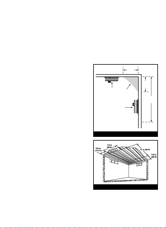
Note A: Maximum coverage established by U.L. is based on providing equal
(10 cm)
4"
MINIMUM
(10 cm)
4"
CEILING
DEAD AIR
SPACE
SIDE
WALL
MINIMUM
(30.5 cm)
12"
MAXIMUM
BEST
HERE
NEVER
HERE
ACCEPTABLE
HERE
response time as sprinkler devices spaced at 10-Ft intervals (100 Sq/Ft) on a
smooth ceiling approximately 15 feet high. Higher ceilings may adversely affect
response time and earlier response time may be obtained by reducing the spacing between alarms.
Note B: Maximum distance is from any wall or ceiling projection extending
down more than 12 inches.
2. RECOMMENDED LOCATION OF ALARMS
• The most favorable mounting location
for a heat alarm is on the ceiling in the
center of the room. At this location the
alarm is closest to all areas of the room
(see figure 3).
EXCEPTION: When the mounting surface
might become considerably warmer or
cooler than the room, such as a poorly
insulated ceiling, below an unfinished attic,
or an exterior wall. In these cases the alarm
should be mounted on an inside wall.
• If the alarm cannot be located in the
center of the room, an off-center location
can be used on the ceiling. When off cen-
FIGURE 1
ter mounting an alarm on the ceiling,
locate it at a minimum of 4" (10 cm) from
the side wall (see figure 3).
• If a ceiling mounting location is not feasible the next logical location for mounting
heat alarms is on the side wall. When
mounting the alarm on the wall, use an
inside wall with the top edge of the alarm
at a minimum of 4" (10 cm) and a maximum of 12" (30.5 cm) below the ceiling
(see figure 1).
• Install Heat Alarms on sloped, peaked or cathedral ceilings at or within 3 ft
(0.9m) of the highest point (measured horizontally). NFPA 72 states: “Smoke
alarms in rooms with ceiling slopes greater than 1 ft in 8 ft (.3m in 2.4m) hori-
FIGURE 2
zontally shall be located on the high side of the room.” NFPA 72 states: “A row
Page 4
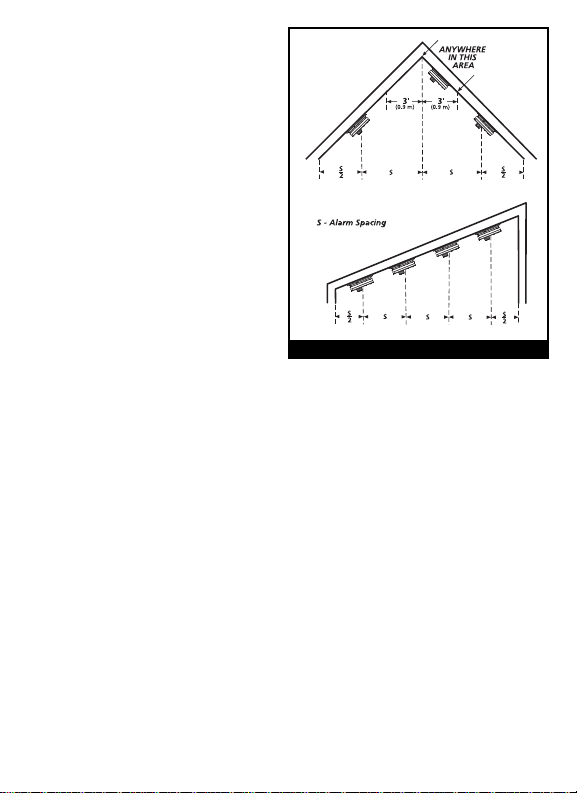
of alarms shall be spaced and located
within 3 ft (0.9m) of the peak of the
ceiling measured horizontally” (see
figure 3).
• In rooms with open joists or
beams, all ceiling mounted alarms
shall be located on the bottom of
such beams (see figure 2).
• Alarms installed on an open-joisted
ceiling shall have their smooth ceiling
spacing reduced to no more than half
of the listed spacing when measured
at right angles to the solid joist (See
figure 2).
MOBILE HOME INSTALLATION
Modern mobile homes have been
FIGURE 3
designed and built to be energy efficient. Install heat alarms as recommended above (refer to RECOMMENDED LOCATIONS and FIGURE 1).
In older mobile homes that are not well insulated compared to present standards, extreme heat or cold can be transferred from the outside to the inside
through poorly insulated walls and roof. This may create a thermal barrier
which can prevent the heat from reaching an alarm mounted on the ceiling. In
such units, install the heat alarm on an inside wall with the top edge of the
alarm at a minimum of 4” (10 cm) and a maximum of 12” (30.5 cm) below the
ceiling (see figure 1).
If you are not sure about the insulation in your mobile home, or if you notice
that the outer walls and ceiling are either hot or cold, install the alarm on an
inside wall.
WARNING: TEST YOUR HEAT ALARM OPERATION AFTER RV OR MOBILE
HOME VEHICLE HAS BEEN IN STORAGE, BEFORE EACH TRIP AND AT
LEAST ONCE A WEEK DURING USE.
3. LOCATIONS TO AVOID
• In front of forced air supply ducts used for heating and air conditioning, near
ceiling fans, or other high air flow areas.
Page 5

• In an area where the temperature may fall below -20ºF or rise above 100ºF.
• Near fluorescent lights – electronic "noise" may cause nuisance alarms.
• Heat alarms are not to be used with detector guards unless the combination
(alarm and guard) have been evaluated and found suitable for that purpose.
4. INSTALLATION INSTRUCTIONS
WIRING REQUIREMENTS
• This smoke alarm should be installed on a U.L. listed or recognized junction
box. All connections should be made by a qualified electrician and all wiring
used shall be in accordance with articles 210 and 300.3(B) of the U.S. National
Electrical Code ANSI/NFPA 70, NFPA 72 and/or any other codes having jurisdiction in your area. The multiple station interconnect wiring to the alarms must
be run in the same raceway or cable as the AC power wiring. In addition, the
resistance of the interconnect wiring shall be a maximum of 10 ohms.
• The appropriate power source is 120 Volt AC Single Phase supplied from a
non-switchable circuit which is not protected by a ground fault interrupter.
• WARNING:This alarm cannot be operated from power derived from a square
wave or modified square wave inverter. These type of inverters are sometimes
used to supply power to the structure in off grid installations, such as solar or
wind derived power sources. These power sources produce high peak voltages
that will damage the alarm.
WIRING INSTRUCTIONS FOR AC QUICK CONNECT HARNESS
CAUTION! TURN OFF THE MAIN POWER TO THE CIRCUIT BEFORE WIRING
THE ALARM.
• For alarms that are used as single station, DO NOT CONNECT THE RED WIRE
TO ANYTHING. Leave the red wire insulating cap in place to make certain that
the red wire cannot contact any metal parts or the electrical box.
• When alarms are interconnected, all interconnected units must be powered
from a single circuit.
• A maximum of 24 Kidde/Lifesaver devices may be interconnected in a multiple
station arrangement. The interconnect system should not exceed the NFPA
interconnect limit of 12 smoke alarms and/or 18 alarms total (smoke, heat,
carbon monoxide, etc.). With 18 alarms interconnected, it is still possible to
interconnect up to a total of 6 remote signaling devices and/or relay modules.
Page 6

• When mixing models which have battery backup (1275, 1276, 1285, 1296,
FUSE OR CIRCUIT BREAKER
RE DBLACK
WH ITE
B
LACK
WH ITE
RE D
CO NN ECTOR
CO NN ECTOR
First
Alarm
Add itional
Alarm
Kidde
Relay Module
SM120X
Add itional
Alarm
Optional Accessory
i12040, i12060, i12080, PE120, PI2000, KN-COSM-IB, HD135F, KN-COB-IC,
KN-COP-IC) with models without battery backup, (1235, i12020, KN-COSM-I,
120X, SM120X, CO120X, SL177i) be advised that the models without battery
backup will not respond during an AC power failure.
• The maximum wire run distance between the first and last unit in an intercon-
nected system is 1000 feet.
• Figure 4 illustrates interconnection wiring. Improper connection will result in
damage to the alarm, failure to operate, or a shock hazard.
• Make certain alarms are wired to a continuous (non-switched) power line.
NOTE: Use standard UL listed household wire (as required by local codes) available at all electrical supply stores and most hardware stores.
Smoke
Alarm
HD135F
Heat
Alarm
Optional
Accessory
Smoke
Alarm
FIGURE 4 INTERCONNECT WIRING DIAGRAM
WIRES ON ALARM HARNESS CONNECTED TO
Black Hot Side of AC Line
White Neutral Side of AC Line
Red Interconnect Lines (Red Wires) of Other
Units in the Multiple Station Set up
BATTERY INSTALLATION
See MAINTENANCE (section 7) for battery installation.
CAUTION! IF THE BATTERY REMINDER FINGER IS NOT HELD DOWN IN
THE BATTERY COMPARTMENT BY THE BATTERY, THE BATTERY DOOR
WILL NOT CLOSE, THE AC QUICK CONNECTOR WILL NOT ATTACH TO THE
ALARM, AND THE ALARM WILL NOT ATTACH TO THE TRIM RING (SEE
SECTION 7, FIGURE 9).
Page 7

MOUNTING INSTRUCTIONS
CAUTION: THIS UNIT IS SEALED. THE COVER IS NOT REMOVABLE!
1. Remove the trim ring from the back of the alarm by holding the trim ring and
twisting the alarm in the direction indicated by the “OFF” arrow on the alarm
cover.
2. After selecting the proper smoke alarm location as described in Section 2 and
wiring the AC QUICK CONNECT harness as described in the WIRING INSTRUCTIONS, attach the trim ring to the electrical box (see figure 5).
3. Use a screwdriver to punch out only the pair of holes in the trim ring that
match your type of electrical box or plaster ring. Mount the trim ring to the
electrical box, using the appropriate holes. NOTE: Use the circle, square and
octagon markings near each mounting hole in the trim ring to help you select
the correct mounting holes (see figure 5).
Rectangular
Plaster Ring
Figure 5 SELECT CORRECT MOUNTING HOLES ON TRIM RING
Circular
Plaster Ring
Octagonal
Electrical Box
4. Pull the AC QUICK CONNECTOR through the center hole in the trim ring and
mount the ring, making sure that the mounting screws are positioned in the
small ends of the keyholes before tightening the screws (see figure 5).
5. Plug the AC QUICK CONNECTOR into the back of the alarm (see figure 6),
making sure that the locks on the connector snap into place. Then push the
excess wire back into the electrical box through the hole in the center of the
trim ring.
6.If you have finished all the WIRING, BATTERY INSTALLATION AND TRIM RING
MOUNTING STEPS, you can install the alarm on the trim ring. Alignment marks
are provided on the side of the alarm and on the trim ring (see figure 7).
Page 8

7. Install the alarm on the trim ring with the indicating marks aligned and rotate
the alarm in the direction of the “ON” arrow on the cover until the alarm
snaps in place (see figure 7).
8. Turn on the AC power. The green AC Power On Indicator should be lit when
the alarm is operating from AC power.
TAMPER RESIST LOCKING PIN: To make your heat alarm tamper resistant, a
locking pin has been provided with your alarm. Using this pin will help deter
children and others from removing the alarm from trim ring. To use the pin,
insert it into the hole in the side of the alarm after the alarm has been installed
on the trim ring (see figure 8).
NOTE: The tamper resist pin will have to be removed in order to change the batteries. Use long nose pliers to pull the pin out of the hole. It is now possible to
remove the alarm from the trim ring.
To remove AC
connector,
squeeze
locking
arms and
pull.
Alignment Marks
Install
Remove
Tamper resistant
locking pin
FIGURE 6 FIGURE 7 FIGURE 8
After installation, TEST your alarm by pressing and holding the test button for
several seconds. You can also use a hand held hair dryer to test your heat alarm.
Complete details on this procedure are outlined in section 5.
CAUTION! Early warning fire detection is best achieved by the installation of
fire detection equipment in all rooms and areas of the household as follows: A
smoke alarm installed in each separate sleeping area (in the vicinity of - but outside of the bedroom) and heat or smoke alarms in the living rooms, dining
rooms, kitchens, hallways, attics, furnace rooms, closets, utility storage rooms,
basements, and attached garages.
Page 9

5. OPERATION AND TESTING
OPERATION: The heat alarm is operating once AC power is applied, fresh batteries are installed and testing is complete. When the heat alarm senses temperatures above 135ºF (plus or minus a few degrees), the horn will sound a loud (85
db) pulsating alarm until the temperature drops below 135ºF.
LED INDICATORS: This heat alarm is equipped with red and green LED indicators.
The red LED is located under the test button and has two modes of operation.
Standby Condition: The red LED will flash every 30-40 seconds to indicate that
Alarm Condition: When the unit detects heat and goes into alarm, the red
WHEN UNITS ARE INTERCONNECTED, only the red LED of the originating alarm
or alarm being tested will flash rapidly. All other units in the interconnect system will sound an alarm but their red LED’s will NOT flash rapidly.
The green LED is located under the other button.
Standby Condition: The green LED will be steady on, indicating the presence
TESTING: Test by pushing the test button on the cover and hold it down for a
minimum of 5 seconds. This will sound the alarm if all the electronic circuitry,
horn, and battery are working. THE TEST SWITCH MAY NOT CAUSE A TEST SIGNAL IF THE AMBIENT TEMPERATURE IS BELOW 32ºF, IN THIS CASE TEST THE
UNIT BY BLOWING HOT AIR AT THE ALARM SENSING ELEMENT WITH A HAIR
DRYER HELD ABOUT 1 FOOT FROM THE UNIT.
If no alarm sounds, check the fuse or circuit breaker supplying power to the
alarm circuit, if the alarm still does not sound the unit may have defective batteries or other failure.
TEST THE ALARM WEEKLY TO ENSURE PROPER OPERATION.
Erratic or low sound coming from your alarm may indicate a defective alarm,
and it should be returned for service (see section 12).
the smoke alarm is operating properly.
LED will flash rapidly (one flash per second). The rapid
flashing LED and pulsating alarm will continue until the
temperature drops below 135 ºF.
of AC power.
Page 10

6. FALSE ALARMS
To avoid false alarms,DO NOT USE WHERE ROOM TEMPERATURES WILL EXCEED
100º F.
Heat alarms respond only to heat. They do not detect smoke. If the unit does
alarm, check for fires first. If a fire is discovered, get out of the house and call
the fire department. If no fire is present check to see if one of the reasons listed
in section 3 may have caused the alarm.
7. MAINTENANCE
ALARM REMOVAL
IF TAMPER RESIST PIN HAS BEEN USED, REFER TO TAMPER RESIST LOCK-
ING PIN IN SECTION 4 FOR PIN REMOVAL INSTRUCTIONS.
To replace the battery, remove the alarm from the trim ring by rotating the alarm
in the direction of the “OFF” arrow on the cover (see section 4, figure 7). To disconnect the AC power harness, squeeze the locking arms on the sides of the
Quick Connector while pulling the connector away from the bottom of the
alarm (see section 4, figure 6).
BATTERY INSTALLATION AND REMOVAL
To replace or install the batteries, you must
first remove the alarm from the trim ring
by following the ALARM REMOVAL instructions at the beginning of this section. After
alarm has been removed, you can open the
battery door and install or replace the battery. Battery installation instructions are
provided on the inside of the battery door.
When installing the battery, press the battery reminder finger down into the battery
compartment and install the battery (see
FIGURE 9
figure 9).
CAUTION! IF THE BATTERY REMINDER FINGER IS NOT HELD DOWN IN THE
BATTERY COMPARTMENT BY THE BATTERY, THE BATTERY DOOR WILL
NOT CLOSE, THE AC QUICK CONNECTOR WILL NOT ATTACH TO THE
ALARM, AND THE ALARM WILL NOT ATTACH TO THE TRIM RING.
Page 11

This smoke alarm uses a 9V carbon backup battery (alkaline and lithium batteries
may also be used). A fresh battery should last for one year under normal operating conditions.
This alarm has a low/missing battery monitor circuit which will cause the alarm
to “chirp” approximately every 30-40 seconds for a minimum of seven (7) days
when the battery gets low. Replace the battery when this condition occurs.
USE ONLY THE FOLLOWING 9 VOLT BATTERIES FOR SMOKE ALARM
REPLACEMENT.
Carbon-zinc type EVEREADY 216 OR 1222; GOLD PEAK 1604P OR 1604S
Alkaline type ENERGIZER 522; DURACELL MN1604, MX1604; GOLD
Lithium type ULTRALIFE U9VL-J
NOTE: WEEKLY TESTING IS REQUIRED!
WARNING! BE SURE TO FOLLOW BATTERY INSTALLATION INSTRUCTIONS
PRINTED ON THE INSIDE OF THE BATTERY DOOR AND USE ONLY THE
BATTERIES SPECIFIED. USE OF DIFFERENT BATTERIES MAY HAVE A DETRIMENTAL EFFECT ON THE SMOKE ALARM.
PEAK 1604A; PANASONIC 6AM6, 6AM-6, 6AM-6PI,
6AM6X, and 6LR61(GA)
CLEANING YOUR ALARM
YOUR ALARM SHOULD BE CLEANED AT LEAST ONCE A YEAR
To clean your alarm, remove it from the mounting bracket as outlined in the
beginning of this section. You can clean the interior of your alarm (sensing
chamber) by using compressed air or a vacuum cleaner hose and blowing or vacuuming through the openings around the temperature sensor located on the
top of the alarm. The outside of the alarm can be wiped with a damp cloth.
After cleaning, reinstall your alarm and test your alarm by using the test button.
If cleaning does not restore the alarm to normal operation the alarm should be
replaced.
After cleaning, reinstall your alarm. Test your alarm by using the test button and
check that the green LED is on.
Page 12

8. LIMITATIONS OF HEAT ALARMS
WARNING: PLEASE READ CAREFULLY AND THOROUGHLY
• HEAT ALARMS ARE NOT DESIGNED TO PROTECT LIFE SAFETY AGAINST
FIRE AND SMOKE. IN MOST FIRES, HAZARDOUS LEVELS OF TOXIC
GASES, SMOKE AND HEAT CAN BUILD UP BEFORE A HEAT ALARM WILL
OPERATE. IN CASES WHERE LIFE SAFETY IS AN ISSUE, HEAT ALARMS
SHOULD ONLY BE USED TO PROVIDE AN ADDED SOURCE OF INFORMATION AND AS A SUPPLEMENT TO THE SMOKE ALARM INSTALLATION.
HEAT ALARMS DO NOT ALWAYS DETECT FIRES, THE FIRE MAY BE A
SLOW SMOLDERING (SMOKE PRODUCING) LOW HEAT PRODUCING
TYPE, THE FIRE MAY BE IN A DIFFERENT ROOM THAN THE ALARM, OR
THE HEAT FROM THE FIRE MAY BYPASS THE ALARM. THIS ALARM WILL
NOT DETECT SMOKE, GASES OR FLAMES.
• HOME FIRES DEVELOP IN DIFFERENT WAYS AND ARE OFTEN UNPREDICTABLE.
NO ONE TYPE OF ALARM (HEAT, PHOTOELECTRIC OR IONIZATION) IS
ALWAYS BEST, AND A GIVEN ALARM MAY NOT ALWAYS PROVIDE WARNING
OF A FIRE. ALSO ALARMS DO HAVE LIMITATIONS. FOR A BATTERY POWERED
ALARM THE BATTERY MUST BE OF THE SPECIFIED TYPE, IN GOOD CONDITION AND INSTALLED PROPERLY. AC POWERED ALARMS WILL NOT OPERATE
IF AC POWER HAS BEEN CUT OFF SUCH AS BY AN ELECTRICAL FIRE OR AN
OPEN FUSE. ALARMS MUST BE TESTED REGULARLY TO MAKE SURE THE BATTERIES AND THE ALARM CIRCUITS ARE IN GOOD OPERATING CONDITION.
• HEAT ALARMS CANNOT PROVIDE AN ALARM IF HEAT DOES NOT REACH THE
ALARM. THEREFORE, HEAT ALARMS MAY NOT SENSE FIRES STARTING IN
CHIMNEYS, WALLS, ON ROOFS, ON THE OTHER SIDE OF A CLOSED DOOR OR
ON A DIFFERENT FLOOR. IF THE ALARM IS LOCATED OUTSIDE THE BEDROOM
OR ON A DIFFERENT FLOOR, IT MAY NOT WAKE UP A SOUND SLEEPER. THE
USE OF ALCOHOL OR DRUGS MAY ALSO IMPAIR ONES ABILITY TO HEAR THE
ALARM. FOR MAXIMUM PROTECTION HEAT ALARMS SHOULD ONLY BE USED
AS A SUPPLEMENT TO SMOKE ALARMS. SMOKE ALARMS SHOULD BE
INSTALLED IN EACH SLEEPING AREA ON EVERY LEVEL OF A HOME AND BE
INTERCONNECTE WITH EACH OTHER AND THE HEAT ALARMS.
• ALTHOUGH HEAT ALARMS WHEN COMBINED WITH SMOKE ALARMS, CAN
HELP SAVE LIVES BY PROVIDING AN EARLY WARNING OF A FIRE, THEY ARE
NOT A SUBSTITUTE FOR AN INSURANCE POLICY. HOME OWNERS AND
RENTERS SHOULD HAVE ADEQUATE INSURANCE TO PROTECT THEIR LIVES
AND PROPERTY.
Page 13

9. GOOD SAFETY HABITS
DEVELOP AND PRACTICE A PLAN OF ESCAPE
• Install and maintain Fire extinguishers on every level of the home and in the
kitchen, basement and garage. Know how to use a fire extinguisher prior to
an emergency.
• Make a floor plan indicating all doors and windows and at least two (2)
escape routes from each room. Second story windows may need a rope or
chain ladder.
• Have a family meeting and discuss your escape plan, showing everyone what
to do in case of fire.
• Determine a place outside your home where you all can meet if a fire occurs.
• Familiarize everyone with the sound of the smoke alarm and train them to
leave your home when they hear it.
• Practice a fire drill at least every six months, including fire drills at night.
Ensure that small children hear the alarm and wake when it sounds. They
must wake up in order to execute the escape plan. Practice allows all occupants to test your plan before an emergency. You may not be able to reach
your children. It is important they know what to do.
• Current studies have shown smoke alarms may not awaken all sleeping
individuals, and that it is the responsibility of individuals in the household that
are capable of assisting others to provide assistance to those who may not be
awakened by the alarm sound, or to those who may be incapable of safely
evacuating the area unassisted.
WHAT TO DO WHEN THE ALARM SOUNDS
• Leave immediately by your escape plan. Every second counts, so don’t waste
time getting dressed or picking up valuables.
• In leaving, don’t open any inside door without first feeling its surface. If hot, or
if you see smoke seeping through cracks, don’t open that door! Instead, use
your alternate exit. If the inside of the door is cool, place your shoulder against
it, open it slightly and be ready to slam it shut if heat and smoke rush in.
• Stay close to the floor if the air is smoky. Breathe shallowly through a cloth,
wet if possible.
• Once outside, go to your selected meeting place and make sure everyone is
there.
Page 14

• Call the fire department from your neighbor’s home - not from yours!
• Don’t return to your home until the fire officials say that it is all right to do so.
There are situations where a smoke alarm may not be effective to protect
against fire as stated in the NFPA Standard 72. For instance:
a) smoking in bed
b) leaving children home alone
c) cleaning with flammable liquids, such as gasoline
10. NFPA REQUIRED PROTECTION
The National Fire Protection Association’s Standard 72 provides the following
information:
Smoke Detection - Where required by applicable laws, codes, or standards for
the specified occupancy, approved single- and multiple-station smoke alarms
shall be installed as follows: (1) In all sleeping rooms Exception: Smoke alarms
shall not be required in sleeping rooms in existing one- and two-family dwelling
units. (2) Outside of each separate sleeping area, in immediate vicinity of the
sleeping rooms. (3) On each level of the dwelling unit, including basements
Exception: In existing one- and two-family dwelling units, approved smoke
alarms powered by batteries are permitted.
Smoke Detection - Are More Smoke Alarms Desirable? The required number of
smoke alarms might not provide reliable early warning protection for those areas
separated by a door from the areas protected by the required smoke alarms. For
this reason, it is recommended that the householder consider the use of additional smoke alarms for those areas for increased protection. The additional
areas include the basement, bedrooms, dining room, furnace room, utility room,
and hallways not protected by the required smoke alarms. The installation of
the smoke alarms in the kitchen, attic (finished or unfinished), or garage is normally not recommended, as these locations occasionally experience conditions
that can result in improper operation.
This equipment should be installed in accordance with the National Fire
Protection Association’s Standard 72 (NFPA, Batterymarch Park, Quincy, MA
02269).
Page 15

11. CAUTION (AS REQUIRED BY THE CALIFORNIA STATE FIRE
MARSHAL)
“Early warning fire detection is best achieved by the installation of fire detection
equipment in all rooms and areas of the household as follows. A smoke alarm
installed in each separate sleeping area (in the vicinity of, but outside of the bedrooms), and heat or smoke alarms in the living rooms,dining rooms, bedrooms,
kitchens, hallways, attics, furnace rooms, closets, utility and storage rooms, basements and attached garages.”
12. SERVICE AND WARRANTY
If after reviewing this manual you feel that your smoke alarm is defective in any
way, do not tamper with the unit. Return it for servicing to: KIDDE Safety, 1016
Corporate Park Dr., Mebane, NC 27302.
1-800-880-6788 (See Warranty for in-warranty returns).
Page 16

FIVE YEAR LIMITED WARRANTY
KIDDE Safety warrants to the original purchaser that the enclosed heat alarm (but not
the battery) will be free from defects in material and workmanship or design under normal use and service for a period of five years from the date of purchase. The obligation
of KIDDE Safety under this warranty is limited to repairing or replacing the heat alarm or
any part which we find to be defective in material, workmanship or design, free of
charge to the customer, upon sending the heat alarm with proof of date of purchase,
postage and return postage prepaid, to Warranty Service Department, KIDDE Safety,
1016 Corporate Park Dr., Mebane, NC 27302.
This warranty shall not apply to the heat alarm if it has been damaged, modified,
abused or altered after the date of purchase or if it fails to operate due to improper
maintenance or inadequate AC or DC electrical power.
THE LIABILITY OF KIDDE SAFETY OR ANY OF ITS PARENT OR SUBSIDIARY CORPORATIONS ARISING FROM THE SALE OF THIS HEAT ALARM OR UNDER THE TERMS OF THIS
LIMITED WARRANTY SHALL NOT IN ANY CASE EXCEED THE COST OF REPLACEMENT
OF THE HEAT ALARM AND, IN NO CASE, SHALL KIDDE SAFETY OR ANY OF ITS PARENT
OR SUBSIDIARY CORPORATIONS BE LIABLE FOR CONSEQUENTIAL LOSS OR DAMAGES
RESULTING FROM THE FAILURE OF THE HEAT ALARM OR FOR BREACH OF THIS OR ANY
OTHER WARRANTY, EXPRESS OR IMPLIED, EVEN IF THE LOSS OR DAMAGE IS CAUSED
BY THE COMPANY’S NEGLIGENCE OR FAULT.
Since some states do not allow limitations on the duration of an implied warranty or do
not allow the exclusion or limitation of incidental or consequential damages, the above
limitations or exclusions may not apply to you. While this warranty gives you specific
legal rights, you may also have other rights which vary from state to state.
Also, KIDDE Safety makes no warranty, express or implied, written or oral, including that
of merchantability or fitness for any particular purpose, with respect to the battery.
The above warranty may not be altered except in writing signed by both parties hereto.
QUESTIONS OR FOR MORE INFORMATION
Call our Consumer Hotline at 1-800-880-6788 or contact
us at our website at www.kidde.com
Kidde, 1016 Corporate Park Drive, Mebane, NC 27302
 Loading...