

Page 1

FireBeta XT+
Extinguishing Coincidence Unit
Part No’s: 23911-K086
Operation and
Maintenance Manual
TM206 1 of 35 Issue 1.0
Page 2

TM206
Contents
1. Introduction 4
2. Safety 5
3. Mounting 5
4. Technical specification 7
5. Front panel layout 8
6. Removing the equipment chassis 9
7. System diagrams 10
8. Connecting to the circuit board 11
8.1 Sounder circuit wiring 11
8.2 Connecting to extinguishing output 12
8.2.1 Solenoid wiring 12
8.2.2 Igniting actuator wiring 12
8.3 Connecting to activation inputs 13
9. Setting up extinguishant monitoring circuit 14
10. Aux 24VDC supply outputs 14
11. Connection to relay contacts 15
11.1 Fault relay 15
st
11.2 1
11.3 2
11.4 Released relay 16
11.5 Aborted relay 16
11.6 Extract relay 16
12. Connection and configuration of status units and ancillary boards 16
12.1 Adding new status units/ancillary boards 17
12.2 Removing status units/ancillary boards 18
13. Wiring to status units/ancillary boards 19
14. Configuration 20
14.1 Extinguishing output mode 20
14.2 Configuring the activation mode 20
14.3 Reset inhibit time 21
14.4 Pre-release delay timer 21
14.5 Extinguishing release time 22
14.6 2
14.7 Released condition 22
14.8 Delay on manual release 23
14.9 Pre-release delay reset disabled 23
14.10 Release timer 24
14.11 R0V not removed on reset 24
14.12 Disable earth fault monitoring 25
14.13 Disable fault output 25
14.14 Invert low pressure switch input 25
14.15 Extinguishing output monitoring levels 26
15. Panel operation – access levels 1 & 2 27
15.1 Normal condition 27
15.2 Access level 2 27
stage alarm relay 15
nd
stage alarm relay 15
nd
stage alarm pulsing/continuous 22
15.2.1 Disable extinguishing release outputs 27
15.2.2 Disable manual release 27
15.2.3 Disable 1
st
stage output 28
TM206 2 of 35 Issue 1.0
Page 3

15.2.4 Disable 2nd stage output 28
15.2.5 Disable released output 28
15.2.6 Disable extract output 29
15.2.7 Turn on extract output 29
15.3 Single input activation 29
15.4 Double input activation 29
15.5 Reset 30
15.6 Sounder fault 30
15.7 Power fault 30
15.8 System fault 30
15.9 Lamp test 30
15.10 Hold condition 31
15.11 Released condition 31
15.12 Low pressure switch 31
15.13 Manual only mode 31
15.14 Manual release 31
15.15 Abort input 31
16. Internal controls 32
16.1 Watchdog reset 32
16.2 Processor reset 32
16.3 Terminate extinguishing 32
16.4 Write enable switch 32
17. Internal indications 33
17.1 Watchdog 33
17.2 System fuse 33
17.3 Man. Release 33
18. Power supply 33
19. Maintenance 34
20. CE Mark 34
21. Commissioning instructions 35
TM206 3 of 35 Issue 1.0
Page 4

1 Introduction
The FireBeta XT+ Extinguishant Coincidence Unit is designed in accordance with European standards
EN12094-1 Fixed fire fighting systems - Components for gas extinguishing systems - Part 1:
Requirements and test methods for electrical automatic control and delay devices.
The FireBeta XT+ ECU is a self contained extinguishing release control unit that can receive
activation signals at supervised inputs via volt free contacts from a fire detection control panel
or addressable output modules
The ECU has an integral, mains powered, EN54-4 compliant battery charger and power
supply.
In addition to the requirements of EN12094-1 the ECU has the following facilities:
…………Delay of extinguishing signal of up to 60 seconds. EN12094-1 Section 4.17
option with requirements.
…………Signal representing the flow of extinguishing agent to indicate the released
condition. EN12094-1 Section 4.18 option with requirements.
…………Monitoring of the status of components by way of a low pressure switch input.
EN12094-1 Section 4.19 option with requirements.
………….Emergency hold device to enable the extinguishing delay time to be
extended. EN12094-1 Section 4.20 option with requirements.
………….Contro l of flooding time to deactivate the releasing output after a set period of
time. EN12094-1 Section 4.21 option with requirements.
…………Manual only mode to disable the release of Extinguishing via
automatic detection devices. EN12094-1 Section 4.23 option with requirements.
…………Triggering of equipment outside the system by way of first and
second stage contacts, extract fan output etc. EN12094-1 Section 4.26 option with
requirements.
…………Activation of alarm devices with different signals to indicate pre-
discharge and released warnings using d ifferent sounds. EN12094-1 Section 4.30 option with
requirements.
……….Emergency Abort device to inhibi t the extinguishing signal until the emergency abort
device has been deactivated and the panel has been reset. EN12094-1 Section 4.27 option with
requirements.
TM206 4 of 35 Issue 1.0
Page 5

2 Safety
Suppliers of articles for use at work are required under section 6 of the Health and Safety at
Work act 1974 to ensure as reasonably as is practical that the article will be safe and without
risk to health when properly used.
An article is not regarded as properly used if it is used ‘without regard to any relevant
information or advice’ relating to its use made available by the supplier.
This product should be installed, commissioned and maintained by trained service personnel
in accordance with the following:
(i) IEE regulations for electrical equipment in buildings
(ii) Codes of practice
(iii) Statutory requirements
(iv) Any instructions specifically advised by the manufacturer
According to the provisions of the Act you are therefore requested to take such steps as are
necessary to ensure that you make any appropriate information about this product available
to anyone concerned with its use.
This equipment is designed to operate from 230V 50Hz mains supplies and is of class 1
construction. As such it must be connected to a protective earth conductor in the fixed wiring
of the installation and a readily accessible double pole disconnect device meeting the
requirements of EN60950/IEC950 which disconnects live and neutral simultaneously shall be
incorporated in the fixed wiring. Switch disconnect devices such as MK Sentry 63A or similar
are suitable for this.
WARNING:
adequately bonded to the protective earth will render the equipment unsafe.
This control panel is environmental class A and is designed for indoor use only at
temperatures between -5
95%.
The IP rating for the enclosure is IP30.
Operation outside of these limits may render the equipment unsafe.
Failure to ensure that all conductive accessible parts of this equipment are
0
C (+/- 3) and +400C (+/- 2) and with a maximum relative humidity of
3 Mounting
The ECU should be mounted on a dry, flat surface, at eye height to the displays and in a level
position such that the enclosure is not distorted.
Screws or bolts of a minimum of 5mm diameter must be used to mount the enclosure in all
four mounting positions.
It should be positioned in an accessible place as agreed with the end user.
Suitable fixings should be used at all fixing points such that the unit is securely mounted and
is not liable to move once fixed.
The ECU should not be mounted in another enclosure or near sources of excessive heat.
Cables should be connected using suitable cable glands fitted to the knockouts provided. If
additional cable entry points are required, all swarf and debris caused by drilling of additional
cable entries must be cleared before power is applied to the panel.
TM206 5 of 35 Issue 1.0
Page 6

Cables should not be installed in the bottom of the enclosure. This space must be kept free
for batteries
.
Side view Front view
5mm diameter screws
Fix to flat surface using suitable wall plugs
TM206 6 of 35 Issue 1.0
Page 7

TM206 7 of 35 Issue 1.0
4 Technical specification
Table 1 - Electrical specifications
ITEM ELECTRICAL RATING COMMENT COMMUNICATION
PARAMETERS
Mains supply 230V AC, 50Hz +10% - 15% (100 Watts maximum) Standard European mains
connection
Mains supply fuse T2A L250V Replace only with similar type
Power supply rating 4 Amps including battery charge 28V +/- 2V
Maximum ripple current 200 millivolts
Battery type (Yuasa NP) 2 x 12 Volt sealed lead acid in series
Battery charge voltage 27.6VDC nominal (temperature compensated) Modulated DC
Battery charge current 1,5A maximum Modulated DC
Current draw in mains fail condition 60 milliamps quiescent – 107 milliamps full alarm
Maximum current draw from
batteries
4 Amps With main power source disconnected
Aux 24V output Fused at 500mA with electronic fuse 200 milliamp maximum continuous load
1st and 2nd stage Sounder outputs 21 to 28V DC Fused at 1A with electronic fuse 1.0 Amp total load over all circuits Voltage reversing DC
Fault relay contact rating 5 to 30VDC 1A Amp maximum for each Maximum ratings not to be exceeded Volt free changeover contact
Fire relay contact rating 5 to 30VDC 1A Amp maximum for each Maximum ratings not to be exceeded Volt free changeover contact
First stage contact rating 5 to 30VDC 1A Amp maximum for each Maximum ratings not to be exceeded Volt free changeover contact
Second stage contact rating 5 to 30VDC 1A Amp maximum for each Maximum ratings not to be exceeded Volt free changeover contact
Extract contact rating 5 to 30VDC 1A Amp maximum for each Maximum ratings not to be exceeded Volt free changeover contact
Terminal capacity 0.5mm2 to 2.5mm
2
solid or stranded wire
Number of sounders per circuit Dependent on type and current consumption See table 2 for sounder types
Monitored input end of line 6K8 +/- 5% ½ Watt resistor Supplied in terminals
Sounder circuit end of line 10K +/- 5% ¼ Watt resistor Supplied in terminals
Extinguishing output end of line 1N4004 Diode Supplied in terminals
No. of sounder circuits (2) 21 to 28V DC 1 x 1st stage and 1 x 2nd stage
Extinguishing release outputs (2) 21 to 28V DC. Fused at 1 Amp 1 Amp maximum load –for 5 minutes
3 Amps for 20 milliseconds
Voltage reversing DC with
calibration facility
Extinguishing release delay Adjustable 0 to 60 seconds (+/- 10%) 5 second steps
Extinguishing release duration Adjustable 60 to 300 seconds 5 second steps
Cabling FP200 or equivalent (Maximum capacitance 1µF, max
inductance 1Mh)
Metal cable glands must be used
Monitored inputs normal threshold
(Allowable EOL)
10K ohm to 2K ohm
Monitored inputs alarm threshold 2K ohms to 150 ohms +/-5%
Monitored inputs s/c threshold 140 ohms to 0 ohms +/-5%
Status unit/Ancillary board
connection
Two wire RS485 connection (EIA-485 specification) Maximum of 7 units per area- RS485
data cable.
(EIA-485 specification)
Status unit power output 21 to 28V DC, Fused at 500mA with electronic fuse 300 milliamp maximum load
Page 8

Table 2 - Compatible sounders
Model Type Manufacturer Comments
BANSHEE ELECTRONIC VIMPEX
WAFER ELECTRONIC VIMPEX
FIRECRYER RANGE ELECTRONIC VOICE VIMPEX
KOBELL MOTORISED VIMPEX
ASKARI ELECTRONIC FULLEON
ROSHNI ELECTRONIC FULLEON
SQUASHNI ELECTRONIC FULLEON
SYMPHONI ELECTRONIC FULLEON
ELECTRONIC BELL ELECTRONIC FULLEON
CFB BELLS MOTORISED FULLEON
B6 AND B8 BELLS SOLENOID FULLEON
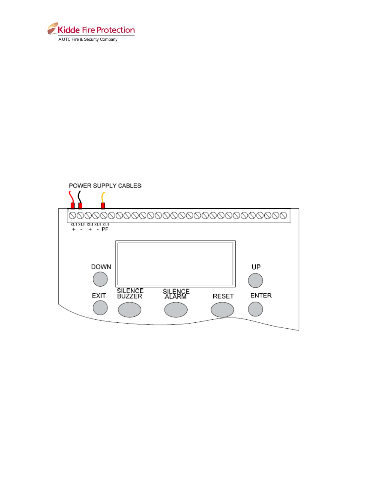
5 Front panel layout
TM206 8 of 35 Issue 1.0
Page 9
6 Removing the equipment chassis
Open the control panel lid using the two 801 lock key.
Before the chassis can be removed it will be necessary to disconnect the power cables from the
connector terminal block on the left hand side of the PCB.
The chassis is held in place by two screws. Undo the two screws and lift the chassis gently away from
the box towards you.
With the chassis removed, there is much more room inside the panel for making off and dressing cables.
When cabling work is complete, the chassis can be re-fitted and the power cables reconnected.
Important! Ensure the power cables are connected correctly.
TM206 9 of 35 Issue 1.0
Page 10

TM206 10 of 35 Issue 1.0
7 System diagrams
Any number of ECU connected to addressable panel
Any number of ECU connected to conventional fire panel using zonal volt free contacts
Page 11

8 Connecting to the circuit board
All connections for field wiring are to rows of terminals along the top and bottom of the circuit board.
Shielded fire alarm cable such as FP200 and metal cable glands must be used for all connections to the
panel.
The shield of the cable must be bonded securely to the enclosure earth via a metal cable gland.
The resistance of any core of any cable must not exceed 25 ohms. The shield of the cable must be
bonded securely to the enclosure via the metal gland.
Wiring should enter the enclosure at the top or back of the panel using the knockouts provided and be
formed tidily to the appropriate terminals.
Terminals are capable of accepting wires of up to 2.5mm
Wiring must not go across the front of the circuit board. If cable entries need to be in positions other than
at the knockouts provided, wiring must be fed behind and well away from the surface of the circuit board.
The space at the bottom of the enclosure is largely occupied by the standby batteries so this must be
borne in mind when considering cable entries.
8.1 Sounder circuit wiring
All sounders must be of the polarised type. If non-polarised sounders are used the control panel will
permanently show a fault condition. See table 2 for a list of compatible sounder types.
Sounder circuits are monitored for open and short circuit faults by placing a 10K 0.25W end of line
monitoring resistor across the last device on the circuit.
Sounder circuits must be wired as a single, radial circuit with no spurs or T junctions to enable the
monitoring circuit to work correctly.
POLARISED
SOUNDER
2
.
POLARISED
SOUNDER
SOUNDER
OUTPUT
TERMINALS
+ IN
-IN
See manufacturers
details for detailed
connection information
+ OUT
-OUT
+ IN
-IN
See manufacturers
details for detailed
connection information
+ OUT
-OUT
Sounder circuit wiring through an MTL778ac I.S. barrier
TM206 11 of 35 Issue 1.0
10K end of
line resistor
Page 12

8.2 Connection to extinguishing output
The Extinguishing output is capable of supplying up to 1 Amp for the maximum duration to a solenoid or
3 Amps for 20 milliseconds to an igniting actuator or Metron.
The wiring for solenoids and igniting actuators is different as shown below. Igniting actuators of different
types or from different manufacturers should not be mixed on the same circuit.
8.2.1 Solenoid wiring
Solenoids must have a resistance of greater than 28 ohms to ensure that the maximum current rating of
the Extinguishing output is not exceeded.
Solenoids should be fitted with a suppression diode to prevent EMF generated by the solenoid when it
de-energises from upsetting the operation of the control panel.
Only polarised solenoids (i.e. solenoids fitted with an internal polarising diode) should be used.
Example of wiring a solenoid
8.2.2 Igniting actuator wiring
A maximum of four igniting actuators can be wired in series. If only one or two actuators are fitted, a 2R2,
2.5 Watt resistor must be wired in series with them to provide the correct monitoring resistance. The end
of line diode can be discarded when igniting actuators are used.
To guarantee firing under all conditions, the total resistance of actuators, monitoring resistor and cable
should not exceed 7 ohms.
EXTING
+
-
EXTING
+
-
TM206 12 of 35 Issue 1.0
3 OR 4 ACTUATORS
WIRED IN SERIES
(MAXIMUM OF 4)
M
M M M
1 OR 2 ACTUATORS
WIRED IN SERIES
M M
FIT 2R2 2.5W RESISTOR
IN SERIES WITH
ACTUATORS IF ONLY 1 OR
2 ACTUATORS ARE USED
Page 13

8.3 Connecting to activation inputs
The ECU has two monitored activation inputs which can be used for activating the extinguishing system.
Each input must have 6k8 0.5W end of line resistor fitted (supplied in terminals) and be triggered by a
470R 1W resistor.
Wiring from volt free contacts from conventional fire panels or addressable modules are shown below.
Activation input 1 –
Volt free contact from addressable
module or conventional fire panel.
Activation input 2 –
Volt free contact from addressable
module or conventional fire panel.
470R 1 Watt Trigger resistor
6k8 0.5 Watt End of Line resistor
TM206 13 of 35 Issue 1.0
Page 14

9 Setting up extinguishing monitoring circuit
The extinguishing output circuit is factory set to monitor the end of line diode that is fitted to the terminals
and will normally show a value of around 270.
If the parameters of the Extinguishing output change e.g. by connecting a solenoid in parallel with the
monitoring diode or removing the diode and fitting igniting actuators, then the extinguishing output
monitoring level will need to be “learnt”. See section 14.16 for details. To do this, operate the ENABLE
CONTROLS keyswitch to put the system into access level 2.
The LCD will show:
Operate the WRITE ENA BLE switch by gently sliding it to the right. The LCD will show:
Press the ENTER button and then the UP button repeatedly until the LCD displays:
The XXX displayed here is the previous (factory level) to which the monitoring level had been sent.
Press the ENTER button. The LCD will now show:
The XXX shown here is the current monitoring level detected on the extinguishing input. Press the
ENTER button to learn the new monitoring level.
Press the UP button to set the monitoring level for output 2 in the same way if it is being used, otherwise
switch the WRITE ENABLE slide switch to the left and check that an open or short circuit fault on the
extinguishing output(s) is detected and shown on the control panel.
10 Aux 24V DC supply output
The terminals for the Aux 24V supply are labelled Aux 24V + and ROV. The ROV terminal is the negative
terminal.
It is possible to have the Aux24V supply outputs removed for a few seconds when the panel is reset.
Aux 24V not removed upon reset is set as default on the ECU. To change this, switch the system to
access level 2 by operating the ENABLE CONTROL keyswitch and then operate the WRITE ENABLE
switch by gently sliding it to the left.
The LCD will show:
Press the ENTER button and then the UP repeatedly until the LCD displays:
TM206 14 of 35 Issue 1.0
Page 15

Press the ENTER button. The LCD will show:
Press the ENTER button. The LCD will show:
Press the exit button.
The Aux 24V supply outputs are fitted with an electronic, self resetting fuse rated at 0.5 Amps to protect
the control panel’s 24V supply in the event of a wiring fault.
Any standing load on the Aux 24V supply outputs must be taken into account when calculating battery
standby times. Standby times will be significantly affected by even modest standing loads on these
outputs. It is recommended that the Aux 24V outputs are NOT used to power standing loads.
Where the Aux 24V supply outputs are used to power electromechanical devices such as relays or door
retainers it is imperative that a suppression diode is fitted across the coil of the device to prevent the
generation of high voltage transients back to the control panel power supply.
11 Connection to relay contacts
Volt free changeover relay contacts are provided for local control and signalling if required. These
contacts are rated for switching signalling circuits only and the maximum ratings listed in Table 1 –
Electrical speci f ic at ions, should not be exceeded under any circumstances.
Typically, the Aux 24V output of the control panel is switched through these relays and used to control
other systems.
11.1 Fault relay
The fault relay is normally energised and will de-energise upon any fault condition on the detection part
or the extinguishing part of the control panel including total loss of power.
11.2 1
The first stage alarm relay will operate upon activation of one of the two monitored activation inputs and
will de-activate only when the panel is reset.
This relay will also operate upon activation of the panel mounted or remote manual release switch.
The stage 1 relay output can be disabled at access level 2 via the menus on the ECU.
11.3 2nd stage alarm relay
Second stage alarm relays will operate when the panel enters the activated condition (i.e. the release
countdown timer has started) and will de-activate only when the panel has been reset from the released
condition.
The stage 2 relay output can be disabled at access level 2 via the menus on the ECU.
st
stage alarm relay
TM206 15 of 35 Issue 1.0
Page 16

11.4 Released relay
The released relay will operate when the module enters the released condition, triggered by activation of
the monitored activation inputs. The released relay will also operate if the panel enters the released
condition via the released pressure switch input.
The Released relay can be disabled at access level 2 via the menus on the ECU.
11.5 Abort relay
The Abort relay will operate when the panel is in the aborted condition, activated via an abort switch
input.
11.6 Extract relay
The extract relay will operate when selected at access level 2. This provides a means to vent a room of
extinguishing gases but prevents the gases from being vented during a discharge.
To switch on the extract relay, operate the ENABLE CONTROL keyswitch and then press ENTER on the
ECU on which the required extract relay is fitted.
The LCD will show:
Press the DOWN button until the display shows:
Press ENTER to turn the extract output on.
The LCD will change to the following:
Pressing ENTER again will turn the extract off.
12 Connection and configuration of Status indicators and Ancillary boards
Important!
The ECU should not be powered during the connection of status indicators or ancillary boards.
Status indicators and ancillary boards require a four-wire connection from the associated ECU to the
corresponding data and power, in and out terminals. Two of the cables carry power to the units (24V)
and the other two carry data.
A four core cable suitable for carrying RS485 data should be used. If this is a twisted pair cable then one
twisted pair should be used for the data connections and the second pair used for the power
connections.
Each status indicator and ancillary board has a 3-bit DIL switch and must be allocated a unique address
between 1 and 7.
The ECU is able to distinguish between status indicators and ancillary boards so it is possible to have a
status indicator set to address 1 and an ancillary board set to address 1 if desired.
TM206 16 of 35 Issue 1.0
Page 17

ADDRESS SWITCH POSITIONS
1
2
3
4
5
6
7
The address switch is located on the bottom left hand corner of the status indicator or ancillary PCB.
Note:
The address is only read when the boards are first powered or if the processor reset switch on the
ancillary board or status indicator is pressed, so address switches should not be altered on a system that
has power applied.
It is important that each individual status indicator and each ancillary board is allocated a unique address
in the range 1 to 7. Units of the same type with the same address will cause intermittent faults to be
displayed.
NOTE:
10 lamp status indicators (Part no’s 23911-K077, 23911-K078 and 23911-K082) are not compatible with
FireBeta XT+ ECU.
12.1 Adding new Status indicators/Ancillary boards
When the system is powered, it will search for connected status indicators and/or ancillary boards
connected to ECU.
If status indicators or ancillary boards are fitted and detected by the ECU, the LCD will display:
X = the number of faults
Press ENTER on the module to which the status indicators or ancillary boards are connected with the
ENABLE CONTROL switch keyswitch off and use the UP button on the module to view the faults. If
status indicators and/or ancillary boards are detected the LCD will display:
X = the address of the status unit found
Or
X = the address of the ancillary board found
TM206 17 of 35 Issue 1.0
Page 18

To accept the status indicators and/or ancillary boards found, turn the ENABLE CONTROL keyswitch on
and slide the WRITE ENABLE switch on the module to which the status indicators or ancillary boards
are connected gently to the left.
The LCD will then display:
X = the address of the status unit found
Or
X = the address of the ancillary board found
When the ENTER button is pressed on the module to which the status indicators or ancillary boards are
connected, the selected status indicator or ancillary board will be added to the system and the next unit
to be added will be displayed. Press the ENTER button on the ECU until all of the units have been
accepted then gently slide the WRITE ENABLE switch on the module to the right.
All of the status indicators and ancillary boards found by the ECU have now been added and
disconnection of any of them will be displayed as a fault on the ECU. If any status indicators are
disconnected, a HOLD activated indication will also be displayed on the ECU and all ancillary boards or
status indicators that remain connected.
With the ENABLE CONTROLS keyswitch off, the LCD will display:
When additional status indicators or ancillary boards are added to the system, these will be shown on the
LCD of the ECU when the system is powered up or the processor reset switch is pressed on the module
to which the status indicators or ancillary board is connected and can be added to the system by
following the procedure above.
12.2 Removing Status indicators/Ancillary boards
If a status indicator or ancillary board needs to be removed from the system, disconnect the status
indicator or ancillary board taking care not to short power supply or data cables. The ECU will display:
Press the processor reset button on the ECU, when the ECU has re-started, it will display:
X = the address of the disconnected status indicator.
Or
TM206 18 of 35 Issue 1.0
Page 19

X = the address of the disconnected ancillary board.
Turn the ENABLE CONTROLS keyswitch on and gently slide the WRITE ENABLE switch to the left.
The LCD will then display:
X = the address of the remaining status indicators
X = the address of the remaining ancillary boards
When the ENTER button is pressed on the module to which the status indicators or ancillary boards are
connected, the selected status indicator or ancillary board will be added to the system and the next unit
to be added will be displayed. Press the ENTER button on the ECU until all of the units have been
accepted then gently slide the WRITE ENABLE on the ECU switch to the right.
Full details of status units and ancillary boards can be found in TM202, TM203 and TM205.
13 Wiring to status units and ancillary boards
The ECU has terminals for data and power connections to FireBeta XT status indicator units and/or
ancillary boards. These terminals are labelled STATUS SERIAL and STATUS POWER. It is important to
wire these terminals with the correct polarity for both the serial data and power wiring.
FireBeta XT+ ECU
TM206 19 of 35 Issue 1.0
To next ancillary
board/Status
indicator
Page 20

Up to seven status indicators and seven ancillary boards can be connected to each ECU. Consideration
must be given to the power consumption of status units and ancillary boards when calculating the
standby battery requirements for the ECU.
The last status unit or ancillary board connected to the ECU must have a terminating link fitted.
Terminating links must be removed from all preceding status units and ancillary boards.
For details of link settings and location, refer to manuals TM203 and TM205.
14 Configuring the ECU
14.1 Extinguishing output mode
The FireBeta XT+ ECU has two extinguishing outputs. These can be configured to operate together at
the same time (common) or be configured as main and reserve outputs.
The factory default setting for the extinguishing outputs is common.
To change this, switch on the ENABLE CONTROL keyswitch and slide the WRITE ENABLE switch on
the module to be configured gently to the left. Press the ENTER button on the ECU. The display will
show:
Press the ENTER button and the display will show:
Press the ENTER button to select main/reserve.
To save the settings, slide the WRITE ENABLE switch gently to the right.
When the ECU is activated, only extinguishing output 1 operate.
There is an additional menu item at access level 2 to allow the reserve extinguishing output to be
selected.
14.2 Activation mode
It is possible to configure the ECU to be activated by coincidence i.e. any 2 zones from a range of zones
or a single zone from a range of zones. The activation mode is factory set to coincidence.
To change this, switch on the ENABLE CONTROLS keyswitch and slide the WRITE ENABLE switch on
the module to be configured gently to the left. Press the ENTER button on the ECU then press the UP
button. The display will show:
Press the ENTER button and the display will show:
Press the ENTER button to select single zone activation mode.
TM206 20 of 35 Issue 1.0
Page 21

To save the settings, slide the WRITE ENABLE switch gently to the right.
Operation of any of detection zone in the range of zones selected to trigger the ECU will put the ECU into
the activated condition.
14.3 Reset inhibit time
It is a requirement of the Extinguishing control panel standard EN12094-1 to inhibit reset of the system
after it has been activated until there is a signal representing the end of the discharge (a released input)
or for an adjustable time period of up to 30 minutes. The factory default for the reset inhibit time is 0.
To change the reset inhibit time, switch on the ENABLE CONTROLS keyswitch and slide the WRITE
ENABLE switch on the module to be configured gently to the left. Press the ENTER button on the ECU
then press the UP button until the display shows:
Press the ENTER button and the display will show:
To change the reset inhibit time, press UP or DOWN buttons until the time required is displayed and then
press ENTER.
To save the settings, slide the WRITE ENABLE switch gently to the right.
Resetting of the ECU after it has been activated will now be prohibited until the reset inhibit time has
elapsed.
14.4 Pre-release delay time
The extinguishing control panel standard EN12094-1 allows for a time delay to be set from activation of
the ECU to operation of the Extinguishing release output. This time may be between 0 and 30 seconds
with a maximum of 5 second steps.
The factory default time delay on the ECU is 30 seconds.
To change the pre-release delay time, switch on the ENABLE CONTROLS keyswitch and slide the
WRITE ENABLE switch on the module to be configured gently to the left. Press the ENTER button on
the ECU then press the UP button until the display shows:
Press the ENTER button and the display will show:
To change the time, press the UP or DOWN buttons until the required time is displayed.
To save the settings, slide the WRITE ENABLE switch gently to the right.
The pre-release delay time will now be set to the chosen value.
TM206 21 of 35 Issue 1.0
Page 22

14.5 Extinguishing release time
The time that the Extinguishing output is active for can be set between 60 and 300 seconds. The factory
default time for this is 60 seconds. It is also possible to disable this timer such that the Extinguishing
outputs remain active until the module is reset. See Release timer menu option section 14.11.
To change the Extinguishing release time, switch on the ENABLE CONTROL keyswitch and slide the
WRITE ENABLE switch on the module to be configured gently to the left. Press the ENTER button on
the ECU then press the UP button until the display shows:
Press the ENTER button and the display will show:
To change the time, press the UP or DOWN buttons until the required time is displayed
To save the settings, slide the WRITE ENABLE switch gently to the right.
The Extinguishing release time will now be set to the chosen value.
14.6 2
nd
stage alarm
The second stage alarm output can be configured to be steady or pulsing at about 1 second on, 1
second off to suit the desired application. The factory default for the second stage alarm is pulsing.
To change the operation of the second stage sounders, switch on the ENABLE CONTROLS keyswitch
and slide the WRITE ENABLE switch on the module to be configured gently to the left. Press the ENTER
button on the ECU then press the UP button until the display shows:
Press the ENTER button and the display will show:
To change to steady second stage alarms, press the ENTER button.
To save the settings, slide the WRITE ENABLE switch gently to the right.
The second stage alarm output will operate in steady mode when the module is activated.
14.7 Released indication
It is possible to select whether the released indication on a module is operated at the same time as the
extinguishing release output operates or by operation of a pressure switch connected to the released,
pressure switch input.
The factory default setting is for the released indication to be operated by operation of a pressure switch
connected to the released, pressure switch input.
To change the operation of the released indication, switch on the ENABLE CONTROLS keyswitch and
slide the WRITE ENABLE switch on the module to be configured gently to the left. Press the ENTER
button on the ECU then press the UP button until the display shows:
TM206 22 of 35 Issue 1.0
Page 23

Press the ENTER button and the display will show:
To change setting, press the ENTER button.
To save the settings, slide the WRITE ENABLE switch gently to the right.
The released indicator will now be lit when the Extinguishing output operates.
14.8 Delay on manual release
The manual release function (panel mounted and remote) can be configured to have a pre-release time
delay (as per the set pre-release time) or to have no pre-release delay allowing immediate operation of
the Extinguishing output when a manual release is operated.
The factory default setting for this is for the manual release to have a delay time the same as the prerelease delay.
To configure the module to have no delay when a manual release is operated, switch on the ENABLE
CONTROLS keyswitch and slide the WRITE ENABLE switch on the module to be configured gently to
the left. Press the ENTER button on the ECU then press the UP button until the display shows:
Press the ENTER button and the display will show:
To change to this, press the ENTER button.
To save the settings, slide the WRITE ENABLE switch gently to the right.
Operation of a manual release will now operate the Extinguishing outputs with no time delay.
14.9 Pre-release delay reset disabled
Once activated, an ECU can not be reset until after the reset inhibit time has expired and the
Extinguishing release timer has expired. It is possible to configure the module such that it can be reset
during the pre-release delay.
The factory default setting is for the pre-release delay reset to be disabled.
To configure the module such that it may be reset during the pre-release delay, switch on the ENABLE
CONTROLS keyswitch and slide the WRITE ENABLE switch on the module to be configured gently to
the left. Press the ENTER button on the ECU then press the UP button until the display shows:
Press the ENTER button and the display will show:
TM206 23 of 35 Issue 1.0
Page 24

To change to this, press the ENTER button.
To save the settings, slide the WRITE ENABLE switch gently to the right.
It will now be possible to reset the module during the pre-release delay but not while the extinguishing
outputs have operated or until after expiry of the reset inhibit time.
Note:
Disabling the Pre-release delay reset does not comply with the requir3ements of EN12094-1.
14.10 Release timer
The release timer can be disabled such that once the Extinguishing output has operated; it remains
operated until the system is reset.
To disable the release timer, switch on the ENABLE CONTROLS keyswitch and slide the WRITE
ENABLE switch on the module to be configured gently to the left. Press the ENTER button on the ECU
then press the DOWN button until the display shows:
Press the ENTER button and the display will show:
To disable the release timer, press the ENTER button.
To save the settings, slide the WRITE ENABLE switch gently to the right.
With the release timer disabled, the Extinguishing outputs will remain operated until the system is reset.
14.11 R0V not removed on reset
It is possible to configure the AUX24V output on the ECU to be removed for a few seconds when the
system is reset.
The factory default setting is for the Aux24V output not to be removed when the system is reset.
To configure the module such that Aux24V output is removed for a few seconds when the system is
reset, switch on the ENABLE CONTROLS keyswitch and slide the WRITE ENABLE switch on the
module to be configured gently to the left. Press the ENTER button on the ECU then press the DOWN
button until the display shows:
Press the ENTER button and the display will show:
To select this option, press the ENTER button.
To save the settings, slide the WRITE ENABLE switch gently to the right.
With the release module configured to remove the R0V output on system reset, the Aux 24V output will
be removed for a few seconds when the reset button is pressed.
TM206 24 of 35 Issue 1.0
Page 25

14.12 Disable earth fault monitoring
The earth fault monitoring facility can be disabled on each module individually.
The factory default setting is for the earth fault monitoring facility to be enabled.
To disable the earth fault monitoring, switch on the ENABLE CONTROL keyswitch and slide the WRITE
ENABLE switch on the module to be configured gently to the left. Press the ENTER button on the ECU
then press the DOWN button until the display shows:
Press the ENTER button and the display will show:
To select this option, press the ENTER button.
To save the settings, slide the WRITE ENABLE switch gently to the right.
The earth fault monitoring facility on the module will now be disabled.
14.13 Disable Fault output
The fault output relay can be disabled on each module individually.
The factory default setting is for the fault output relay to be enabled.
To disable the fault output relay, switch on the ENABLE CONTROL keyswitch and slide the WRITE
ENABLE switch on the module to be configured gently to the left. Press the ENTER button on the ECU
then press the DOWN button until the display shows:
Press the ENTER button and the display will show:
To select this option, press the ENTER button.
To save the settings, slide the WRITE ENABLE switch gently to the right.
The fault output relay on the module will now be disabled.
Note:
Disabling the fault output does not comply with the requirements of EN54-2.
14.14 Invert low pressure switch input
To enable low pressure switches to be used which have normally closed rather than normally open
contacts, it is possible to invert the low pressure switch input.
The factory default setting is for the low pressure switch input to use a normally open contact.
TM206 25 of 35 Issue 1.0
Page 26

To invert the low pressure switch input, switch on the ENABLE CONTROL keyswitch and slide the
WRITE ENABLE switch on the module to be configured gently to the left. Press the ENTER button on
the ECU then press the DOWN button until the display shows:
Press the ENTER button and the display will show:
To select this option, press the ENTER button.
To save the settings, slide the WRITE ENABLE switch gently to the right.
The low pressure switch input will now require a normally closed contact via a 470R trigger resistor and
6K8 end of line resistor for correct supervision.
14.15 Extinguishing output monitoring levels
The Extinguishing outputs are able to monitor both solenoid and igniting actuator releasing devices. To
do this the outputs must be calibrated with the releasing device and the cable, fitted as it will be in the
working system.
The Extinguishing outputs are fitted with a 1N4004 diode at the factory and the default monitoring level
will be set at approximately 206 but may be between 204 and 208.
To change the monitoring level for extinguishing output 2, switch on the ENABLE CONTROL keyswitch
and slide the WRITE ENABLE switch on the module to be configured gently to the left. Press the ENTER
button on the ECU then press the DOWN button until the display shows:
Press the ENTER button and the display will show:
The XXX here will be the actual monitoring level read by the module.
To save this setting press the ENTER button.
To set the monitoring level for extinguishing output 1, press the DOWN button. The display will show:
Press the ENTER button and the display will show:
The XXX here will be the actual monitoring level read by the module.
To save this setting press the ENTER button.
TM206 26 of 35 Issue 1.0
Page 27

To save the settings, slide the WRITE ENABLE switch gently to the right.
The extinguishing output levels will now be set and any significant variation detected in the monitoring
levels will be announced as an EXTING. O/P fault.
15 Panel operation – Access levels 1 and 2
15.1 Normal condition
Under normal conditions and in Manual & Auto mode, the ECU will have only the green Power On LED
lit. With the ENABLE CONTROL keyswitch off the LCD on the ECU will show:
In Manual only mode the ECU will have an additional, Manual only yellow LED lit and the LCD will show:
The ECU has 3 access levels. Access level 1 is available at all times and allows operation of SILENCE
BUZZER and the Lamp test function (hold down EXIT button for more than 2 seconds). Access level 2 is
enabled after operation of the front panel mounted ENABLE CONTROL keyswitch. Access level 3 allows
configuration options to be set on the ECU following operation of the WRITE ENABLE while in access
level 2 (ENABLE CONTROLS keyswitch operated).
15.2 Access level 2
When the ENABLE CONTROLS keyswitch is operated the LCD on the ECU will show:
Press the ENTER button to view the following menu options.
15.2.1 Disable Extinguishing release outputs.
To disable both of the Extinguishing release outputs, press the UP button on the module while at access
level 2.
The display will show:
Press the ENTER button to select this function. The display will show:
The yellow disabled LED on the ECU will be lit.
Turn the ENABLE CONTROL keyswitch off to leave the disablement active. To re-enable the
extinguishing outputs repeat the procedure above.
15.2.2 Disable Manual release
To disable all Manual release inputs (front panel mounted and remotely connected); press the UP button
on the module while at access level 2 until the module displays:
TM206 27 of 35 Issue 1.0
Page 28

Press the ENTER button to select this function. The yellow disabled LED will be lit and the display will
show:
Turn the ENABLE CONTROL keyswitch off to leave the disablement active. To re-enable the manual
release facility, repeat the procedure above.
15.2.3 Disable Stage 1 output
To disable the 1
st
Stage relay output, press the UP button on the module while at access level 2 until the
display shows:
Press the ENTER button to select this function. The display will show:
The yellow disabled LED will be lit.
Turn the ENABLE CONTROL keyswitch off to leave the disablement active. To re-enable the Stage 1
relay output repeat the procedure above.
15.2.4 Disable Stage 2 output
To disable the 2
nd
Stage relay output, press the UP button on the module while at access level 2 until the
display shows:
Press the ENTER button to select this function. The display will show:
The yellow disabled LED will be lit.
Turn the ENABLE CONTROL keyswitch off to leave the disablement active. To re-enable the Stage 2
relay output repeat the procedure above.
15.2.5 Disable Released output
To disable the Released relay output, press the UP button on the module while at access level 2 until the
display shows:
Press the ENTER button to select this function. The display will show:
The yellow disabled LED will be lit.
TM206 28 of 35 Issue 1.0
Page 29

Turn the ENABLE CONTROL keyswitch off to leave the disablement active. To re-enable the Released
relay output repeat the procedure above.
15.2.6 Disable Extract output
To disable the Extract relay output, press the UP button on the module while at access level 2 until the
display shows:
Press the ENTER button to select this function. The display will show:
The yellow disabled LED will be lit.
Turn the ENABLE CONTROL keyswitch off to leave the disablement active. To re-enable the Extract
relay output repeat the procedure above.
15.2.7 Turn on Extract output
To turn on the extract relay output, press the DOWN button on the module while at access level 2 until
the display shows:
Press the ENTER button to select this function. The display will show:
The yellow disabled LED on the module that has been disabled will be lit.
Turn the ENABLE CONTROL keyswitch off to leave the Extract output active. To turn off the Extract
output, repeat the procedure above.
Note:
The extract output does not turn off when the module is reset.
15.3 Single input activation
Upon activation of a single monitored activation input, the activated LED will flash, the 1
contact will operate, the 1
st
stage sounder will operate and the LCD will show:
Pressing the Silence alarm button on the detection module will turn off the 1
st
stage sounder output.
15.4 Double input activation
Upon activation of a second monitored activation input with the ECU in Automatic/Manual mode with the
Hold inputs inactive and where the Disable Extinguishing function has not been invoked, the ECU will
respond as follows:
TM206 29 of 35 Issue 1.0
st
stage relay
Page 30

a) The 2
b) The 2
c) The Activated indicator will illuminate.
d) The display will indicate:
nd
stage alarm output will operate.
nd
stage relay contact will operate.
and show the time remaining until release in seconds.
e) The Extinguishing output will operate after the configured delay time and for the configured
duration.
f) The display will show :
for the duration of the release time.
When the ECU is activated (i.e. the Activated indicator is lit) it shall not be possible to reset until the
Reset Inhibit timer has elapsed.
15.5 Reset
To reset the ECU, insert the ENABLE CONTROL key, turn to the right then press the RESET button.
The ECU will reset only after the Reset Inhibit timer has expired once the activated condition has been
established.
15.6 Sounder fault
A fault on the wiring to the detection module sounder circuits will cause the general Fault LED to
illuminate and the LCD to display.
or
15.7 Power fault
Failure of the mains power or disconnection of the standby battery supply will cause the general Fault
LED to illuminate and the LCD to display:
15.8 System fault
The System Fault and general fault LEDs will illuminate if the configuration memory has not been set or
has become corrupted.
15.9 Lamp test
Indicators on the ECU can be tested by holding down the EXIT button for more than 2 seconds.
TM206 30 of 35 Issue 1.0
Page 31

15.10 Hold condition
Activation of the Hold input or a fault on the monitored wiring of the Hold circuit will cause the Hold
Activated indicator to illuminate on the module and any status units or ancillary boards connected to it.
If the ECU is in the activated condition and the pre-release timer is running then the extinguishing
release sequence will be halted and the pulsing 2
seconds off.
nd
stage sounders shall change to 1 second on, 2
Release of the Hold input will re-start the pre-release timer from the beginning.
15.11 Released co ndition
The released pressure switch input will be connected to a pressure switch mounted on the extinguishing
cylinder which operates when the extinguishing gas has been released. This will activate the released
indicator on the ECU. If the extinguishing gas has been released by mechanical means i.e. the ECU is
not in the activated condition, operation of the released pressure switch input will establish the Released
condition.
15.12 Low pressure switch
The low pressure switch input will be connected to a pressure switch on the extinguishing cylinder and
will operate if the pressure in the cylinder falls below a set point. This will happen after the extinguishing
gas has been released or because of a leak. The fault LED on the ECU will illuminate and the panel
buzzer will sound.
15.13 Manual only mode
The mode of the system can be toggled between Manual Only and Automatic & Manual by operating the
Mode select keyswitch on the ECU.
When a module is in Manual only mode, the extinguishing gas cannot be released by the operation of
automatic detectors.
The mode can also be changed to manual by the external mode select input or by a keyswitch on a
status unit. Any mode select input that is switched to Manual only mode will override any keyswitches
switched to Automatic and Manual mode. All inputs must be switched to Manual and Automatic mode for
a module to be in Automatic and Manual mode.
15.14 Manual Release
ECU may be manually activated by one of the following:
• The manual release control on the front of the ECU
• A remotely mounted Manual release callpoint connected to the monitored manual release inputs
• A manual release control mounted on a status indicator.
Activation of any of these Manual release controls will immediately activate the ECU and begin the prerelease timer if configured to have a time delay for Manual release inputs.
15.15 Abort input
The ECU has the facility for connection of an Abort control. Operation of the Abort input during the prerelease delay time will cancel the extinguishing release timer i.e. the Extinguishing will not be released.
The module can be immediately reset from this condition.
Activation of the Abort input in a non-alarm condition will indicate an abort circuit fault and disable the
gas extinguishing release circuit
TM206 31 of 35 Issue 1.0
Page 32

16 Internal controls
16.1 Watchdog reset
If the microprocessor on the ECU fails to carry out its operation correctly it will attempt to restart. The
ECU will show the general Fault and System Fault LEDs on the front panel, the CPU fault inside the
panel will illuminate and the buzzer will sound. This fault can only be cleared by pressing the
WATCHDOG RESET button located inside the control panel. The control panel buzzer will continue to
sound until the watchdog activation is reset.
16.2 Processor reset
If the microprocessor on the ECU fails to run correctly it can be reset by pressing the PROCESSOR
RESET button inside the control panel.
16.3 Terminate Extinguishing
Once the extinguishing outputs have been operated they can not be switched off until after the reset
inhibit timer has elapsed. For test purposes a terminate Extinguishing button is provided which will
terminate operation of the extinguishing outputs and allow the system to be reset.
16.4 Write enable switch
It is necessary to protect the configuration memory of the ECU while the system is running normally. To
do this a memory WRITE ENABLE switch is provided on each module. This switch must be in the on
position before any changes can be made to the configuration. The switch can be fragile and should be
operated with care.
Internal controls on ECU
Exting.Term.
Proc.
W/dog ResetReset
.
Address
Write Enable
TM206 32 of 35 Issue 1.0
Page 33

17 Internal indications
17.1 Watchdog
Indicates that the processor has failed to correctly execute code and has been re-started by the
watchdog circuit. The WATCHDOG RESET switch must be pressed to clear the Watchdog fault
condition.
If the fault does not clear the ECU is probably damaged and needs the circuit board replacing.
17.2 System fuse
Indicates that the ECU main fuse has been overloaded and the ECU has shut down. Remove and review
all loads then re-connect one at a time.
17.3 Man. Release
Indicates that either the front panel mounted or a remotely connected Manual release control has been
operated. This indication can only be cleared by power cycling the module or pressing the processor
reset switch.
18 Power supply
The ECU requires a 230V (+10%/-15%), 50/60Hz, AC mains power supply which connects to the fused
terminal block labelled “230V”.
The ECU has a 20mm T2A L250V mains fuse.
The fuse should only be replaced with fuses of the same or similar types.
The maximum loading on the power supply must be carefully considered when connecting externally
powered equipment such as sounders and solenoids
Exceeding the maximum power supply rating may cause a fuse or other protective device to
operate and render the equipment inoperative until the fuse is replaced or protective devices are
reset.
The table below can be used to calculate the loading of the ECU.
Current in milliamps
ECU Max alarm load 105
ECU total sounder load
ECU Extinguishing output load
ECU Aux 24V supply
TOTAL LOAD (must be less than 3A)
The output voltage of the power supply is 28V DC +/- 2V and the total current rating is 4A.
The incoming mains cable should be routed well away from other lower voltage wiring by a distance of at
least 50mm.
Mains wiring should include an earth conductor, which is securely bonded to the building earth and
should enter the enclosure as close as possible to the mains terminal block. Mains wires should be kept
very short inside the enclosure and secured together close to the mains terminal block with a cable tie.
The maximum capacity batteries that should be fitted are 7Ah.
The maximum current drawn from the batteries when the main power source is disconnected is 4 Amps.
TM206 33 of 35 Issue 1.0
Page 34

Battery leads are supplied wired to the power supply along with a link to connect the two batteries
together.
Important!
The polarity of the batteries must be carefully observed when connecting. Wrongly connected
batteries could cause damage to the control panel.
19 Maintenance
The ECU does not require any specific maintenance but should the control panel become dirty it can be
wiped over with a barely damp cloth. Detergents or solvents should not be used to clean the ECU and
care must be taken that water does not enter the enclosure.
The control panel contains sealed lead acid batteries to provide standby power in the event of mains
failure. These batteries have a life expectancy of around 4 years and should be tested in accordance
with the battery manufacturer’s recommendations annually to determine their suitability for continued
standby applications.
Testing of the Extinguishing system should only be carried out by trained personnel and must be done
with appropriate isolation measures in place to ensure that accidental discharge of the Extinguishing
agent is avoided.
Should the control panel become faulty the complete electronic assembly and front plate can be
replaced.
Before replacing any parts the configured options should be noted and both mains and battery power
must be removed before the work is started.
The field wiring should be carefully labelled and removed from the terminals.
The faulty PCB plate assembly can now be taken out of the panel by removing the 2 screws.
Fitting the new PCB is the reverse of the procedure for removing the board.
20 CE Mark
All control panels have a label affixed to the inside of the lid which displays the CE mark as well as other
information relating to the panel.
This label should not be removed under any circumstances.
TM206 34 of 35 Issue 1.0
Page 35

21 Commissioning instructions
Before applying power to the panel, any solenoids or igniting actuators must be physically isolated from
the panel by disconnecting both wires, this will prevent any accidental release of extinguishing gas.
When power is applied and if all connections are correct, only the green Power On and either the
Automatic/Manual or Manual Only indicators should be illuminated.
If any fault indicators are illuminated the wiring to the appropriate input or output should be checked an all
faults cleared before proceeding.
Once the ECU is fault free, it can be configured with the desired options.
Once the ECU has been configured the system should be thoroughly tested to ensure that it responds as
expected and required.
After satisfactory testing, any final connections should be made (such as to the extinguishing release
actuator).
A record of the configuration options that have been set should be recorded in the tables below and
provided as part of the documentation recommended by BS5839:Part 1:2002 section 40.2 b).
CONFIGURATION OPTION WRITE SETTING
EXTINGUISHING OUTPUT MODE =
ACTIVATION MODE =
FIRST ACTIV. ZONE =
LAST ACTV. ZONE =
RESET INHIBIT TIME =
PRE-REL. DELAY TIME =
EXTING. RELEASE TIME =
PULSED ACTIV. ALARMS ?
STEADY ACTIV. ALARMS ?
RELEASED IND. ON RELEASE INPUT ?
RELEASED IND. ON EXTING RELEASE ?
DELAY ON MANUAL RELEASE ?
NO DELAY ON MANUAL RELEASE ?
PRE-REL DELAY RESET ENABLED ?
PRE-REL DELAY RESET DISABLED ?
RELEASE TIMER ENABLED ?
RELEASE TIMER DISABLED ?
R0V NOT REMOVED ON SYSTEM RESET ?
R0V REMOVED ON SYSTEM RESET ?
EARTH FAULT ENABLED ?
EARTH FAULT DISABLED ?
FAULT OUTPUT ENABLED ?
FAULT OUTPUT DISABLED ?
LOW PRESS. I/P NORMAL ?
LOW PRESS. I/P INVERTED ?
EXTING. O/P 1 LEVEL ?
EXTING. O/P 2 LEVEL ?
TM206 35 of 35 Issue 1.0
 Loading...