

Page 1
A UTC Fire & Security Company
Argonite
System Description
FEATURES
®
Effective: July 2012
K-38-1000
• Inert Gas Clean Agent Fire Suppression
• Safe for Personnel and Equipment
• Leaves No Residue
• Environmentally Friendly
DESCRIPTION
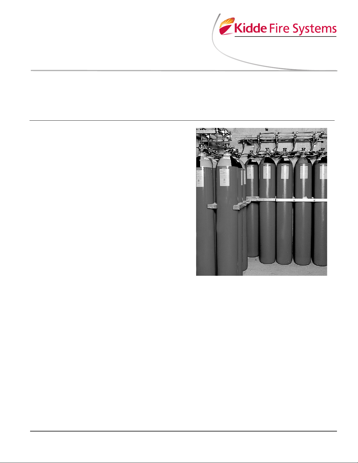
Kidde Argonite® Fire Protection Systems are clean
agent, automatic extinguishing systems that use Argonite
(IG-55) and consist of four basic components and their
associated accessories:
• Argonite Cylinders and Components,
• Completer Kits,
• Control Panels,
• Detection and Alarm Devices.
Argonite is an inert gas mixture, in equal parts, of Nitrogen and Argon. Both substances are naturally occurring
and present in the atmosphere. Argonite is safe for use in
occupied spaces and poses no threat to the environment.
1. Argonite Components consist of the agent cylinders,
cylinder racking and the agent discharge nozzles.
2. The Completer Kits provide all the basic components necessary to operate the Argonite cylinders.
The kits consist of hoses, connection fittings, pressure gauges, actuation devices required to operate
the cylinder valve and warning signs to be displayed
in the area(s) protected by an Argonite fire extinguishing system.
3. The Control Panels vary in features and complexity
but in all cases are used to monitor the detection,
actuate the alarms, initiate the agent discharge and
control auxiliary functions such as shut down of vital
equipment and ventilation dampers.
4. The Detection and Alarm devices provide fire detection by means of thermal or smoke detectors, audible and visual pre-alarm warnings and annunciation
of the Argonite discharge.
• Actuation by Solenoid or Manual Actuator
• Three Available High-pressure
(2900 PSI [200 bar]) Cylinder Sizes
• FM Approved/ULC Listed
AGENT DESCRIPTION
Argonite is a mixture of 50% pure Nitrogen and 50% pure
Argon. Argonite contains only naturally occurring substances, and as such, has no ozone depletion potential
and no direct global warming potential.
Argonite extinguishes by means of reducing the oxygen
content within a room to the point at which fire can no
longer burn, but without compromising the safety of individuals present. There are no toxicological factors associated with the use of Argonite. Argonite will not
decompose or produce any by-products when exposed
to a flame from a fire condition.
Most Argonite systems are designed to extinguish fires
with a minimum agent concentration of 37.9% achieved
within one minute. This results in extinguishment of the
fire and an oxygen concentration of 13%.
Argonite is stored as a gas within the cylinder assembly.
It is available at a storage pressure of 2900 PSI (200
bar).
Page 2
USABLE CYLINDER CAPACITY
Siz e Fill
English Metric at 2900 PSI at 200 Bar
972 cu. in.
15.9 L
*
9.57 lb. 4.34 kg
4079 cu. in.
66.7 L
*
40.15 lb. 18.21 kg
4893 cu. in. 80.0 L 48.13 lb. 21.83 kb
Cylinder
Area Covera ge @
38% Concentration/70°F (21°C)
15.9 L
*
228.8 ft.3 (6.47 m3)
66.7 L
*
959.8 ft.3 (27.17 m3)
80.0 L 1150.6 ft.
3
(32.58 m3)
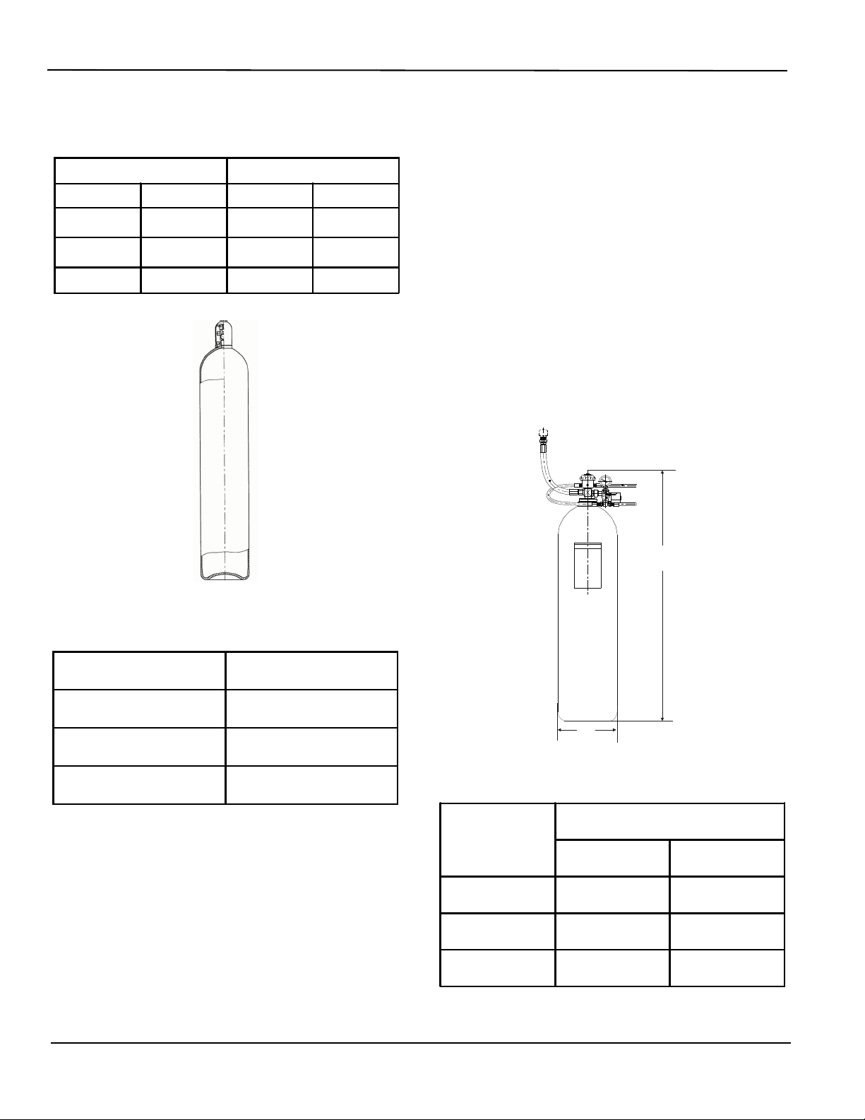
A
B
Cylinder Size
Dimension
A
B
(Diameter)
15.9 L
*
39.07 in.
(992.38 mm)
7.00 in.
(177.80 mm)
66.7 L
*
64.41 in.
(1636.10 mm)
10.49 in.
(266.45 mm)
80.0 L
68.81 in.
(1747.77 mm)
11.25 in.
(285.75 mm)
Three cylinder sizes are available (see Table 1).
Table 1. Cylinder Capacity
CYLINDER AND VALVE ASSEMBLY
Argonite cylinders are available in three different sizes.
The 2900 PSI (200 bar) cylinders are uniquely color
coded to allow for quick and easy identification. The cylinders are red with yellow-green at the cylinder shoulder.
Because Argonite is stored as a gas, the cylinders have
no dip tube and can be mounted in either the vertical or
horizontal position.
The cylinder valve, required for all system cylinders,
allows for connection of the cylinders into the system.
The valve provides connections for electric, pneumatic
and manual release of the cylinder contents, as well as a
discharge outlet, connected by a discharge hose, to the
distribution piping.
The actuator operates on a 1 to 10 ratio requiring only
300 PSI (21 bar) for the 2900 PSI (200 bar) system to
operate the valve. The following are the connections provided on the valve.
Figure 1. Argonite Cylinder
Table 2. Argonite cylinder Area Coverage
EQUIPMENT DESCRIPTION
The Kidde Fire Systems Argonite Fire Protection System
can be released electrically, manually or pneumatically.
The following is a description of the various components
associated with the systems.
* DISCONTINUED
Figure 2. Cylinder Dimensions
Table 3. Cylinder Dimensions
- 2 -
Page 3
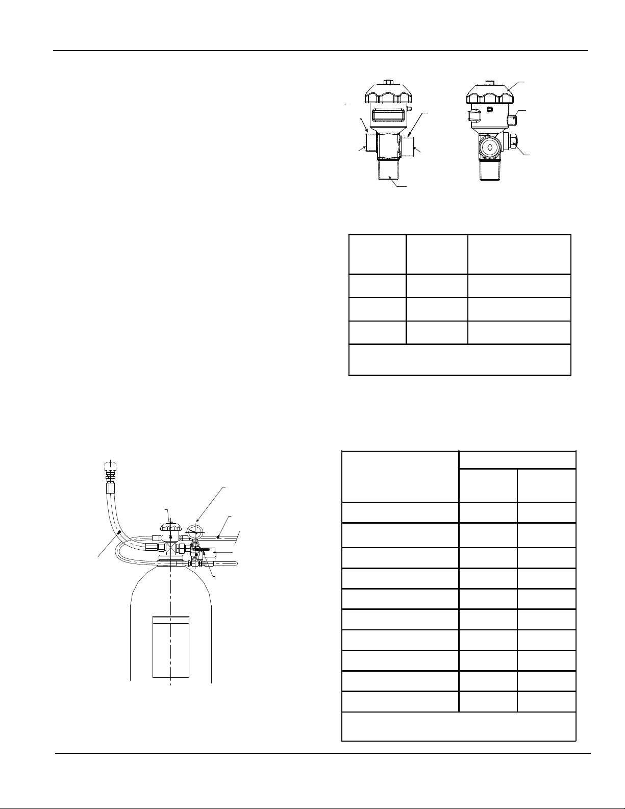
1. Manual/Pneumatic Actuator Connection:
DISCHARGE
HOSE
CYLINDER
VALV E
PRESSURE GAUGE
WITH SUPERVISORY
PRESSURE SWITCH
PILOT HOSE
(TO SLAVE CYLINDERS)
SOLENOID, 24 VDC
MANUAL ACTUATOR
M25 x 1.5
FRONT VIEW
M25 x 1.5
SIDE VIEW
FILLING
OUTLET
FILLING
GAUGE PORT
CONNECTION TO
ARGONITE CYLINDER
HANDLE FOR
FILLING ONLY
1/4” BSP
PILOT CONNECTION
BURST DISC
(21 PSI [300 BAR]
SETPOINT)
Part Number
Cylin der
Assembly
(Filled
Cylinder/Valve)
Description
38-100159-001
15.9 L
*
200 bar; DOT and TC versions
38-100667-001
66.7 L
*
200 bar; DOT and TC versions
38-100800-001 80.0 L 200 bar; DOT and TC versions
Note:
DOT=Department of Transportation (US)
TC=Transport Canada
Description
Completer Kits
Primary (Qty.)
P/N
38-109802-001
Slave (Qty.)
P/N
38-109803-001
Solenoid Valve 1 0
Pressure Gauge with
Supervisory Pressure Switch
11
Manual Release 1 0
Pilot Hose #1 1 0
Pilot Hose #2 1 0
Pilot Hose #3 0 1
Bleeder Valve 1 0
Tee piece for hose connection 2 1
Discharge Hose 1 1
Inle t St e m A sse m b ly 1 1
Note: If cylinders are used in a Main/Reserve system, use decal
P/N 31033 (Main Decal) and P/N 31034 (Reserve Decal).
Each cylinder valve must be fitted with either a Pilot or
Slave type actuator.
The Pilot actuator provides a manual (pull pin turn handle) actuator and connections from an electrical solenoid
and pressure switch assembly. The pilot actuator also
has connections to adjacent slave cylinder actuators to
discharge entire groups of cylinders virtually simultaneously.
The Slave actuator is purely pneumatic; it receives pressure from the pilot actuator and opens its associated cylinder valve.
2. Solenoid Valve, Pressure Gauge and Supervisory
Pressure Switch Connection:
This is a threaded port that serves for the connection of
one of the following:
• Solenoid Valve, Pressure Gauge and Supervisory Pressure Switch for pilot actuator connections.
• Pressure Gauge and Supervisory Pressure
Switch for slave actuator connections.
3. Discharge Outlet:
The cylinder valve outlet is connected to the distribution
piping by a flexible hose with 1/2-inch steel fittings.
Additional features of the valve include a Burst Disc,
designed to rupture upon excessive internal pressure,
and an external Bleeder Valve with indicator that acts as
a pressure relief valve.
Figure 4. Argonite Cylinder Valve
Table 4. Argonite Cylinder and Valve Assembly Data
* DISCONTINUED
COMPLETER KIT COMPONENTS
Either a pilot or a slave completer kit is required to complete the installation of each Argonite cylinder.
Table 5. Completer Kit Data
Figure 3. Argonite Cylinder and Valve Assembly
- 3 -
Page 4

SOLENOID AND PRESSURE GAUGE ASSEMBLY
TEE FITTING, 19 MM HEX
(CONNECTION TO VALVE)
P/N 38-509816-001
TOP VIEW
(SHOWN ON CYLINDER)
SOLENOID, 24 VDC
P/N 38-509834-001
GAUGE WITH
SUPERVISORY
PRESSURE SWITCH
P/N 38-109891-001
MANUAL
PNEUMATIC ACTUATOR
P/N 38-509841-001
SOLENOID,
24 VDC
BLEEDER VALVE
P/N 38-509840-001
CONNECTION
TO CYLINDER VALVE
36 MM HEX
FRONT VIEW SIDE VIEW
HIGH-PRESSURE
REINFORCED RUBBER HOSE
1/4 IN. (6.4 MM); 60° FLARE
SWIVEL NUT
1/4 IN. (6.4 MM) CONNECTOR
15¾ IN. (400 MM) LONG
TO TEE PIECETO TEE PIECE
PRESSURE
INLET
PRESSURE
INLET
WITH SUPERVISORY PRESSURE SWITCH
The solenoid/pressure gauge assembly provides an electrical means (24 Vdc) of actuating the system as well as a
visual means to determine the pressure within the pilot
cylinder.
This unit includes an integral supervisory pressure switch
and is supplied with a pilot flex hose #1. The supervisory
pressure switch consists of one normally open (N.O.)
contact that changes state upon loss of cylinder pressure.
PILOT FLEX HOSE #1, P/N 38-509818-001
This 1/4-inch ID reinforced rubber flex hose has threaded
connections to allow interface between the pilot cylinder
solenoid/pressure gauge assembly and pilot manual/
pneumatic actuator. It is supplied with the pilot solenoid
assembly.
Figure 6. Pilot Flex Hose #1
MANUAL/PNEUMATIC ACTUATOR,
P/N 38-509841-001
The manual/pneumatic actuator supplied with the pilot
completer kit is required on the pilot cylinder to manually
actuate the cylinder valve as well as to supply pressure
to actuate any slave cylinders. Interconnection between
cylinders is by means of high-pressure flex hoses.
Figure 5. Solenoid and Pressure Switch Gauge
PRESSURE GAUGE ASSEMBLY
WITH SUPERVISORY PRESSURE SWITCH,
P/N 38-109891-001
This unit is required for the slave cylinders to provide a
local visual means to determine the pressure within the
slave cylinder.
The pressure gauge assembly includes an integral
supervisory pressure switch, consisting of one N.O. contact that changes state upon loss of cylinder pressure.
Assembly with Supervisory Pressure Switch
Figure 7. Manual/Pneumatic Actuator
- 4 -
Page 5

TEE PIECE FOR HOSE CONNECTIONS,
TO CYLINDER
VALVE ACTUATION
OUTLET TO
ACTUATE CYLINDER
INLET FROM
SOLENOID OR
PRIMARY CYLINDER
1/4 IN. (6.4 MM); 60° FLARE
SWIVEL NUT
HIGH-PRESSURE
REINFORCED RUBBER HOSE
1/4 IN. (6.4 MM) CONNECTOR
LENGTH
Part Number Description Length
38-509817-001
Pilot Hose #3 between cylinder
actuation pieces
10-5/8 in.
(270 mm)
38-509820-001
Pilot Hose #2 between actuator and
cylinder valve
17-3/4 in.
(450 mm)
1/2 IN. (12.7 MM)
SWIVEL NUT
HIGH-PRESSURE
REINFORCED RUBBER HOSE
3/8 IN. (9.5 MM); 60° FLARE
SWIVEL NUT
3/8 IN. (9.5 MM) CONNECTOR
15¾ IN. (406 MM) LONG
CONNECTION FOR
MANIFOLD
3/4” NPT
0.79 in.
(20 mm)
2.24 in.
(57 mm)
0.59 in.
(15 mm)
1/2” BSP
CONNECTION FOR
DISCHARGE HOSE
1.06
HEX
60°
P/N 38-509816-001
The tee piece is supplied with each of the completer kits.
It provides the interface with the pilot assembly (through
a high pressure flex hose) to simultaneously operate the
slave cylinder pneumatically.
Figure 8. Tee Piece
BLEEDER VALVE FOR ACTUATOR,
P/N 38-509840-001
A bleeder valve is included with the Pilot Completer Kit to
prevent an accidental accumulation of pressure within
the pilot lines, which, if not bled to atmosphere, could
cause a false discharge. Connection requires a copper
gasket between the bleeder valve and pneumatic actuator.
DISCHARGE FLEX HOSE, P/N 38-509819-001
This flex hose has 1/2-inch threaded connections to allow
interface between the cylinder valves and the discharge
manifold (if applicable). Where more than one cylinder is
connected to a common manifold, check valves are
required at the end of each discharge flex hose.
Figure 10. Discharge Flex Hose
CHECK VALVE ASSEMBLY, P/N 38-509833-001
To prevent accidental discharge of the Argonite into unintended areas, a check valve is required for each discharge hose in all multi-cylinder systems. All Kidde Fire
Systems manifolds are constructed of threaded pipe with
welded check valve connections and include
pre-installed check valves. All customer connections are
via threaded pipe.
Note: For single cylinder systems, a 1/2-inch BSP x
1/2-inch FNPT adapter is required to connect the
discharge hose (BSP) to the Schedule 160 pipe
(NPT).
PILOT FLEX HOSES
This 1/4-inch ID reinforced rubber flex hose has threaded
connections to allow interface between components.
Figure 9. Pilot Flex Hose
Table 6. Pilot Flex Hose Data
Figure 11. Check Valve Assembly
- 5 -
Page 6

FLOW RESTRICTOR
FLOW
BOLT*
CLASS 1500#
FLANGE*
NUT*
GASKET*
ORIFICE PLATE
RESTRICTOR
* PROVIDED BY
INSTALLER
STAMPED WITH
ORIFICE DIA.
STAMPED WITH
PART NUMBER
CONNECTION FOR
DISTRIBUTION
PIPE WORK
NPT
NPT
38-XX0003-XXX
The restrictor assembly reduces the initial Argonite pressure from the discharge manifold to between 174 and
870 PSI (12 and 60 bar) before entering the discharge
piping. The size of the orifice within the restrictor is determined through calculations based upon the required flow
and discharge time.
Larger diameter restrictors, up to 4 in. (102 mm) connection, are available for very large system requirements. An
orifice plate is custom drilled to the specific requirements
of the project as determined by computerized flow calculations.
Note: Flanged restrictor for large system requirements.
Only the orifice plate is provided.
Figure 13. Restrictor Female NPT/Female NPT,
Sizes 1/2-inch to 2 inches
Table 8. Flow Restrictor Data
Figure 12. Flow Restrictor
Table 7. Flow Restrictor Sizes
Part Number Description
38-250001-xxx 2-1/2 in. Flow Restrictor
38-300001-xxx 3 in. Flow Restrictor
38-400001-xxx 4 in. Flow Restrictor
Part Number
Flow Restrictor FNPT x FNPT Pipe Diameter
(NPT)
38-050003-xxx 1/2 in. (13 mm) Brass, Code 035 to 075
38-100003-xxx 1 in. (25 mm) Brass, Code 050 to 130
38-150003-xxx 1-1/2 in. (38 mm) Brass, Code 085 to 220
38-200003-xxx 2 in. (51 mm) Stainless Steel, Code 115 to 270
- 6 -
Page 7

SELECTOR VALVES
REDUCING BUSHING*
PRESSURE RELIEF DEVICE,
P/N 38-509836-001
SELECTOR VALVE,
1/2” TO 2” NPT
RESTRICTOR
1/2” TO 2” NPT
OUTLET FROM
RESTRICTOR TO
HAZARD #2
OUTLET FROM
RESTRICTOR TO
HAZARD #1
*NOTE: ALL FITTINGS, NIPPLES AND HOSES ARE PROVIDED BY INSTALLER
HANDLE FOR
MANUAL OPERATION
CYLINDER MANIFOLD
OUTLET
FITTING TYPICAL
3000# MIN.
NIPPLE TYPICAL
SCH. 160 MIN.
REDUCING BUSHING*
PRESSURE REGULATOR
WITH VENTED ELBOW,
P/N 38-509803-001
ACTUATION HOSE
TYPICAL,
120 PSI (8 BAR)
NORMAL WORKING PRESSURE*
H
R
W
Argonite systems are particularly suited to the use of
selector valves, where one central storage of agent is
used to provide protection to two or more hazard areas.
Selector valves are available in six sizes, and are pneumatically operated. One common pressure regulator and
vented elbow are also required to reduce the actuation
pressure to each set of selector valves.
NOZZLES
The brass discharge nozzles are available in four basic
sizes 1/2-inch, 3/4-inch, 1-inch and 1-1/2-inch. Each is fitted with a drilled orifice to assure proper flow rates, agent
quality and proper discharge timing as determined by
flow calculations. Maximum nozzle spacing for room
mounted nozzles should not exceed 18.8 feet (5.7 m)
square. Nozzle height should not exceed 16 feet (4.9 m)
from a single layer of nozzles.
Figure 14. Selector Valve System
Table 9. Selector Valves and Components
Part Number Description
38-609800-001 1/2 in. (13 mm) Pipe Diameter
38-609800-002 3/4 in. (19 mm) Pipe Diameter
38-609800-003 1 in. (25 mm) Pipe Diameter
38-609800-004 1-1/4 in. (32 mm) Pipe Diameter
38-609800-005 1-1/2 in. (38 mm) Pipe Diameter
38-609800-006 2 in. (52 mm) Pipe Diameter
38-509803-001 Pressure regulator kit with relief
120 PSI (8.3 bar) preset for selector
valves
Figure 15. Nozzles (37 mm)
Table 10. Argonite Discharge Nozzle Data
Argonite Discharge Nozzle
Part Number
Size (R)
NPT
38-300502-xxx 1/2 in.
(13 mm)
38-300752-xxx 3/4 in.
(19 mm)
38-301002-xxx 1 in.
(25 mm)
38-301502-xxx 1-1/2 in.
(38 mm)
1
An orifice plate within the nozzle is custom drilled to the specific
requirements of the project as determined by computerized flow
calculations.
Orifice
Dia.
3 to
10 mm
7 to
14 mm
10 to
18 mm
15 to
26 mm
1
Height
(H)
1-9/16 in.
(40 mm)
1-7/8 in.
(48 mm)
2-3/8 in.
(60 mm)
3-3/16 in.
(81 mm)
Width
(W)
7/8 in.
(22 mm)
1-1/8 in.
(29 mm)
1-7/16 in.
(37 mm)
2 in.
(51 mm)
- 7 -
Page 8

Figure 16. Typical Argonite Pilot Completer Kit
1/2” DISCHARGE
HOSE
PILOT HOSE #2
TEE FITTING
PRESSURE GAUGE
PRESSURE SWITCH
WITH 1/2” FLEX CONDUIT
PILOT HOSE #1
MANUAL
ACTUATOR
TEE FITTING
PILOT LINE
BLEEDER VALVE
24 VDC SOLENOID
FRONT REAR
PRESSURE GAUGE
WITH SUPERVISORY
PRESSURE SWITCH
PILOT HOSE #3
DISCHARGE HOSE
PILOT LINE
BLEEDER VALVE
Figure 17. Typical Argonite Pilot and
Slave Completer Kit
Kidde is a registered trademark of Kidde-Fenwal, Inc.
Argonite is a registered trademark of Ginge Kerr.
This literature is provided for informational purposes only. KIDDE-FENWAL, INC.
assumes no responsibility for the product’s suitability for a particular application.
The product must be properly applied to work correctly.
If you need more information on this product, or if you have a particular problem or
question, contact KIDDE-FENWAL, INC., Ashland, MA 01721. Telephone: (508)
K-38-1000 Rev AC © 2012 Kidde-Fenwal Inc.
A UTC Fire & Security Company
400 Main Street
Ashland, MA 01721
Ph: 508.881.2000
Fax: 508.881.8920
www.kiddefiresystems.com
 Loading...