

Page 1

Alarmline II Digital Linear
Heat Sensor Cable
Technical Manual
P/N 20-8501-509-DL03-04 • ISS 09APR18
Page 2

Copyright
©
2018 UTC Fire & Security. All rights reserved.
Trademarks and
patents
Alarmline and
Technical Manual
UTC
Other trade names used in this document may be trademarks or
registered trademarks of the manufacturers or vendors of the
respective products.
Manufacturer
Thermocable Flexible Elements Ltd.,
Pasture
Authorized EU manufacturing representative:
UTC Fire & Security B.V.
Kelvinstraat 7, 6003 DH Weert, Netherlands
Revision
04
20
cannot be disposed of as unsorted municip al was te in the Europ ean
Union. For proper recycling, return this product to your local supplier
upon the purchase of equivalent new equipment, or dispose of it at
designated collection points. For more
www.recyclethis.info.
Contact information
For contact information, see:
Technical helpline:
Sales enquiries:
e
Alarmline II Digital Linear Heat Sensor Cable
name and logo are trademarks of
Fire & Security.
Lane, Clayton, Bradf or d BD14 6LU.
.
.
12/19/EU (WEEE directive): Products marked with this symbol
information see:
firesecurityproducts.com.
+44 (0) 1908 281981
+44 (0) 1908 281981
-mail: kidde_airsense_techsupport@kiddeuk.co.uk
Page 3

Content
Important information ii
Chapter 1 Introduction 1
Overview 2
Regulatory information 4
Technical specifications 5
Chapter 2 Design and installation 9
Design guidelines 10
Installation 12
Chapter 3 Commissioning 19
Passive checks 20
Functional testing 20
Chapter 4 Application guidelines 23
Overview 24
Conveyor belts 25
Escalators and moving walkways 27
Cable trays and racks 28
Floating roof storage tanks and bund areas 29
Cold storage and freez er war ehous es 31
Index 33
Alarmline II Digital Linear Heat Sensor Cable Technical Manual i
Page 4

Important information
Limitation of liability
To the maximum extent permitted by applicable law, in no event will UTCFS be
liable for any lost profits or business opportunities, loss of use, business
interruption, loss of data, or any other indirect, special, incidental, or
consequential damages under any theory of liability, whether based in contract,
tort, negligence, product liability, or otherwise. Because some jurisdictions do not
allow the exclusion or limitation of liability for consequential or incidental
damages the preceding limitation may not apply to you. In any event the total
liability of UTCFS shall not exceed the purchase price of the product. The
foregoing limitation will apply to the maximum extent permitted by applicable law,
regardless of whether UTCFS has been advised of the possibility of such
damages and regardless of whether any remedy fails of its essential purpose.
Installation in accordance with this manual, applicable codes, and the instructions
of the authority having jurisdiction is mandatory.
While every precaution has been taken during the prepar ati on of this man ual to
ensure the accuracy of its contents, UTCFS assumes no responsibility for errors
or omissions.
Product warnings and disclaimers
THESE PRODUCTS ARE INTENDE D FOR SALE TO AND INSTALLATION BY
QUALIFIED PROFESSIONALS. UTC FIRE & SECURITY CANNOT PROVIDE
ANY ASSURANCE THAT ANY PERSON OR ENTITY BUYING ITS
PRODUCTS, INCLUDING ANY “AUTHO RIZED DEALER” OR “AUTHORIZED
RESELLER”, IS PROPERLY TRAINED OR EXPERIENCED TO CORRECTLY
INSTALL FIRE AND SECURITY RELATED PRODUCTS.
For more information on warranty disclaimers and product safety information,
please check https://firesecurityproducts.com/policy/product-warning/ or scan the
QR code:
ii Alarmline II Digital Linear Heat Sensor Cable Technical Manual
Page 5

Advisory messages
Advisory messages alert you to conditions or practices that can cause unwanted
results. The advisory messages used in this document are shown and described
below.
WARNING: Warning messages advise you of hazards that could result in injury
or loss of life. They tell you which actions to take or to avoid in order to prevent
the injury or loss of life.
Caution: Caution messages advise you of possible equipment damage. They tell
you which actions to take or to avoid in order to prevent the damage.
Note: Note messages advise you of the possible loss of time or effort. They
describe how to avoid the loss. Notes are also used to point out important
information that you should read.
Note: Kidde Products Ltd. has taken every care to ensure that Alarmline II Digital
Linear Heat Detection systems are as simple to install as possible but in case of
difficulty, please contact our Help Line to ensure trouble free installation and
operation. Kidde Produ c ts Ltd. takes no responsibility for damage or injury
occasioned as a result of failing to install or operate the equipment in accordance
with these instructions.
Alarmline II Digital Linear Heat Sensor Cable Technical Manual iii
Page 6

iv Alarmline II Digital Linear Heat Sensor Cable Technical Manual
Page 7

Chapter 1
Introduction
Summary
This chapter provides an introduction to the product.
Content
Overview 2
Operation 2
Product range 3
Regulatory information 4
UL/ULC listings 4
FM approvals 5
Technical specifications 5
Alarmline II Digital Linear Heat Sensor Cable Technical Manual 1
Page 8
Chapter 1: Introduction
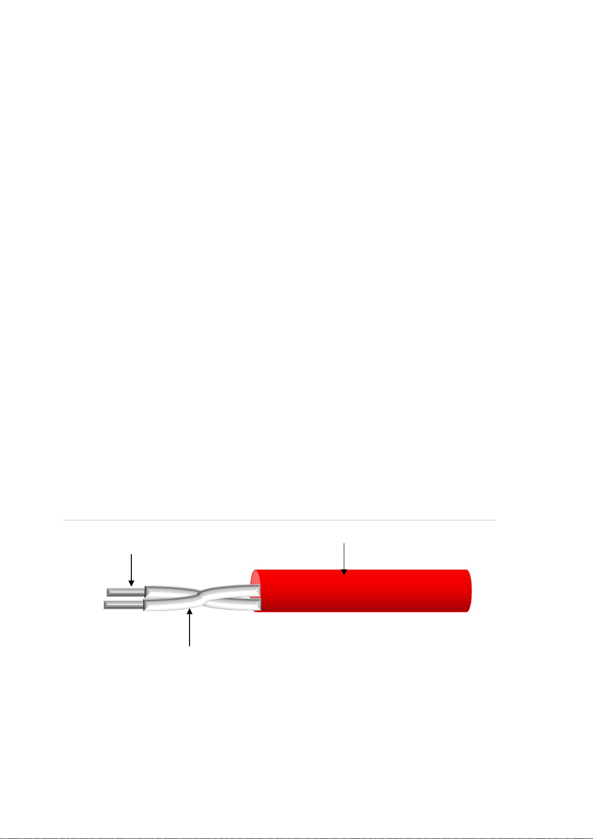
Tri-metallic cores
Protective coating
Advanced temperature-sensitive polymer
Overview
Alarmline II Digital Sensor Cables are a flexible durable and cost-effective form of
fire detection, suitable for protecting a wide range of commercial and industrial
applications.
They provide flexibility in installation enabling them to be used for general area
protection or proximity detection close to a specific point of risk. A wide range of
alarm temperatures, protective coatings, and installation fixings ensure system
design and installation is specific to the risk. Alarmline II Digital Sensor Cables
are especially suited for use in confined areas or areas with harsh environmental
conditions where the use of other forms of detection is limited.
Alarmline II Digital Sensor Cables can be easily integrated to any fire control
panel through a moni to r ed inp ut (a conventional detection zone, zone monitor
unit, or switch monitor unit, etc.). The Digital Location Control Unit provides
additional functionality to the Alarmline II Digital Sensor Cable system by being
able to determine the alarm location along extended lengths of digital sensor
cable (up to 3000 m).
This manual provides technical information, installation guidelines, and design
recommendations for a selection of typical applications (it does not cover all
possible applications – contact Kidde Prod uc t s Ltd. technical support for further
design and installation advice).
Operation
Alarmline II Digital Sensor Cables are constructed from a twisted pair of trimetallic conductors covered with an advanced temperature-sensitive polymer. A
protective outer coating is then extruded over the twisted pair.
Figure 1: Cable construction
2 Alarm l i ne II Digital Li near Heat Sensor Cable T echnical Manual
Page 9

Chapter 1: Introduction
Part
AD68
AD68N
AD68P
AD68SS
AD88
AD88N
AD88P
AD88SS
AD105
AD105N
AD105P
AD105SS
AD185N
AD185SS
The two inner cores of the sensor cable are tightly twisted together to provide a
mechanical tension bet ween them. When the temperature-sensi ti ve polymer
reaches a specified temperature it begins to soften, the tension between the two
inner cores forces the two conductors together creating a short circuit.
The simplistic operation of the Alarmline II Digital Sensor Cable makes it
compatible with any control equipment capable of accepting contact closure type
initiating devices.
Product range
The Alarmline II Digital S ensor Cable range consists of five fixed-temperature
alarm cables, each with a range of protective coatings.
Table 1: Alarmline II Digital Sensor Cable product range
number Description Comments
Alarmline II Digital Sensor Cable – 68°C
(155°F) PVC
Alarmline II Digital Sensor Cable – 68°C
(155°F) Nylon
Alarmline II Digital Sensor Cable – 68°C
(155°F) Polypropylene
Alarmline II Digital Sensor Cable – 68°C
(155°F) Stainless Steel over PVC
Alarmline II Digital Sensor Cable – 88°C
(190°F) PVC
Alarmline II Digital Sensor Cable – 88°C
(190°F) Nylon
Alarmline II Digital Sensor Cable – 88°C
(190°F) Polypropylene
Alarmline II Digital Sensor Cable – 88°C
(190°F) Stainless Steel over PVC
Alarmline II Digital Sensor Cable – 105°C
(221°F) PVC
Alarmline II Digital Sensor Cable – 105°C
(221°F) Nylon
Interior applications, general area
coverage
Chemical/UV protection, exterior
applications
Increased chemical protection in
caustic environments
Increased mechanical protection
Interior applications, general area
coverage
Chemical/UV protection, exterior
applications
Increased chemical protection in
caustic environments
Increased mechanical protection
Interior applications, general area
coverage
Chemical/UV protection, exterior
applications
Alarmline II Digital Sensor Cable – 105°C
(221°F) Polypropylene
Alarmline II Digital Sensor Cable – 105°C
(221°F) Stainless Steel over PVC
Alarmline II Digital Sensor Cable – 185°C
(365°F) Nylon
Alarmline II Digital Sensor Cable – 185°C
(365°F) Stainless steel over Nylon
Alarmline II Digital Linear Heat Sensor Cable Technical Manual 3
Increased chemical protection in
caustic environments
Increased mechanical protection
Chemical/UV protection, exterior
applications
Chemical/UV and mechanical
protection
Page 10

Chapter 1: Introduction
Part
AD2
AD2
Cable
AD68
AD68N
AD88
AD88N
AD105
number Description Comments
18 Alarmline II Digital Sensor Cable – 218°C
(424°F) Silicon e
18SS Alarmline II Digital Sensor Cable – 218°C
(424°F) Stainless steel over Silicone
Chemical/UV protection, exterior
applications
Chemical/UV and mechanical
protection
Additional coated cables are available for special applications:
• Polypropylene outer coating: Provides increased chemical protection within
caustic environments.
• Stainless steel outer braid: Provides increased mechanical protection.
For further information regarding the specialist coatings, contact your local sales
representative.
Regulatory information
UL/ULC listings
The sensor cables listed below have been tested and approved by UL and ULC
to UTHV Heat actuated devices for special application and UQGS Heatautomatic fire detectors.
UL and ULC listed, file number S35630. Categories UTHV, UTHV7, UQGS, and
UQGS7: "Heat activated devices for Special applications”.
Table 2: UL/ULC listings
Alarm temperature Outer coating Spacing
68°C (155°F) PVC Maximum spacing 10.6 m (35 ft.)
between sensor cable runs for
general area coverage
68°C (155°F) Nylon Maximum spacing 4.5 m (15 ft.)
between sensor cable runs for
general area coverage
88°C (191°F) PVC Maximum spacing 10.6 m (35 ft.)
between sensor cable runs for
general area coverage
88°C (191°F) Nylon Maximum spacing 4.5 m (15 ft.)
between sensor cable runs for
general area coverage
105°C (221°F) PVC Maximum spacing 10.6 m (35 ft.)
between sensor cable runs for
general area coverage
4 Alarm l i ne II Digital Li near Heat Sensor Cable T echnical Manual
Page 11

Chapter 1: Introduction
Cable
AD105N
AD185N
AD2
Cable
AD68
AD88
AD105
AD218
Alarm
temperature
Outer coating
Outer colour
Outer diameter
Ambient
temperature
Installation
temperature
Alarm temperature Outer coating Spacing
105°C (221°F) Nylon Maximum spacing 4.5 m (15 ft.)
between sensor cable runs for
general area coverage
185°C (365°F) Nylon Proximity detection only
18 218°C (424°F) Silicone Proximity detection only
FM approvals
The sensor cables listed below have been tested and approved by FM (Fire
Detection, Heat Activated).
Table 3: FM approvals
Alarm temperature Outer coating Spacing
68°C (155°F) PVC Maximum spacing 9 m (30 ft.)
between sensor cable runs for
general area coverage
88°C (191°F) PVC Maximum spacing 9 m (30 ft.)
between sensor cable runs for
general area coverage
105°C (221°F) PVC Maximum spacing 7.6 m (25 ft.)
between sensor cable runs for
general area coverage
235°C (455°F) Silicone Proximity detection only
Technical specifications
Table 4: AD68 range
AD68 AD68N AD68P AD68SS
Red Black Red Red
PVC Nylon Polypropylene
68°C (155°F)
Stainless steel
over PVC
3.6 mm
(±0.12 mm)
0.142 in.
(±0.005 in.)
2 × tri-metallic conductors Ø 0.912 mm (0.036 in.)
Alarmline II Digital Linear Heat Sensor Cable Technical Manual 5
4.44 mm
(±0.12 mm)
(0.175 in.
(±0.005 in.)
45°C (113°F) max.
−10°C (14°F) min.
4.5 mm
(±0.12 mm)
(0.177 in.
(±0.005 in.)
4.1 mm
(±0.12 mm)
(0.161 in.
(±0.005 in.)
Page 12

Chapter 1: Introduction
Operating
temperature
Bend radius
Voltage rating
Insulation rating
Resistance
Capacitance
Inductance
Alarm
temperature
Outer coating
Outer colour
Outer diameter
Ambient
temperature
Installation
temperature
Operating
temperature
Bend radius
Voltage rating
Insulation rating
Resistance
Capacitance
Inductance
AD68 AD68N AD68P AD68SS
50 mm (2 in.) min., extended to 100 mm (4 in.) for low temperature
30 VAC, 42 VDC max.
1 kV tested protective outer coat
90.5 Ω/km (27.6 Ω/1000 ft.) max. per conductor at 20°C
<120 pF/m (<37 pF/ft.)
<1.6 µH/m (<0.49 µH/ft.)
Table 5: AD88 range
White Black White White
3.6 mm
−40°C (−40°F) min.
environments
AD88 AD88N AD88P AD88SS
88°C (190°F)
PVC Nylon Polypropylene
(±0.12 mm)
0.142 in.
(±0.005 in.)
4.44 mm
(±0.12 mm)
(0.175 in.
(±0.005 in.)
4.5 mm
(±0.12 mm)
(0.177 in.
(±0.005 in.)
Stainless steel
over PVC
4.1 mm
(±0.12 mm)
(0.161 in.
(±0.005 in.)
2 × tri-metallic conductors Ø 0.912 mm (0.036 in.)
69°C (156°F) max.
−10°C (14°F) min.
−40°C (−40°F) min.
50 mm (2 in.) min., extended to 100 mm (4 in.) for low temperature
environments
30 VAC, 42 VDC max.
1 kV tested protective outer coat
89.5 Ω/km (27.3 Ω/1000 ft.) max. per conductor at 20°C
<85 pF/m (<26 pF/ft.)
<1.72 µH/m (<0.52 µH/ft.)
6 Alarm l i ne II Digital Li near Heat Sensor Cable T echnical Manual
Page 13

Chapter 1: Introduction
Alarm
temperature
Outer coating
Outer colour
Outer diameter
Ambient
temperature
Installation
temperature
Operating
temperature
Bend radius
Voltage rating
Insulation rating
Resistance
Capacitance
Inductance
Alarm
temperature
Outer coating
Outer colour
Outer diameter
Ambient
temperature
Installation
temperature
Operating
temperature
Bend radius
Table 6: AD105 range
AD105 AD105N AD105P AD105SS
PVC Nylon Polypropylene
105°C (221°F)
Stainless steel
over PVC
White Black White White
3.6 mm
(±0.12 mm)
0.142 in.
(±0.005 in.)
4.44 mm
(±0.12 mm)
(0.175 in.
(±0.005 in.)
4.5 mm
(±0.12 mm)
(0.177 in.
(±0.005 in.)
4.1 mm
(±0.12 mm)
(0.161 in.
(±0.005 in.)
2 × tri-metallic conductors Ø 0.912 mm (0.036 in.)
69°C (156°F) max.
−10°C (14°F) min.
−40°C (−40°F) min.
50 mm (2 in.) min., extended to 100 mm (4 in.) for low temperature
environments
30 VAC, 42 VDC max.
1 kV tested protective outer coat
91 Ω/km (27.7 Ω/1000 ft.) max. per conductor at 20°C
<73 pF/m (<22 pF/ft.)
<1.65 µH/m (<0.5 µH/ft.)
Table 7: AD185 range
Nylon Stainless steel over PVC
Red White
4.44 mm (±0.12 mm)
AD185N AD185SS
185°C (365°F)
5 mm (±0.12 mm)
(0.175 in. (±0.005 in.)
(0.197 in. (±0.005 in.)
2 × tri-metallic conductors Ø 0.912 mm (0.036 in.)
125°C (257°F) max.
−10°C (14°F) min.
−40°C (−40°F) min.
50 mm (2 in.) min., extended to 100 mm (4 in.) for low temperature
environments
Alarmline II Digital Linear Heat Sensor Cable Technical Manual 7
Page 14

Chapter 1: Introduction
Voltage rating
Insulation rating
Resistance
Capacitance
Inductance
Alarm
temperature
Outer coating
Outer colour
Outer diameter
Ambient
temperature
Installation
temperature
Operating
temperature
Bend radius
Voltage rating
Insulation rating
Resistance
Capacitance
Inductance
30 VAC, 42 VDC max.
1 kV tested protective outer coat
91 Ω/km (27.7 Ω/1000 ft.) max. per conductor at 20°C
<90 pF/m (<27 pF/ft.)
<1.62 µH/m (<0.49 µH/ft.)
Table 8: AD218 range
Silicone rubber Stainless steel over silicone
Green Green
AD185N AD185SS
AD218 AD218SS
UL/ULC approval at 2 18° C ( 424°F)
FM approval at 235°C (455°F)
5 mm (±0.1 mm)
(0.196 in. (±0.004 in.)
5.5 mm (±0.11 mm)
(0.216 in. (±0.04 in.)
2 × tri-metallic conductors Ø 0.912 mm (0.036 in.)
170°C (338°F) max.
−10°C (14°F) min.
−40°C (−40°F) min.
63.5 mm (2.5 in.) min., extended to 127 mm (5 in.) for low temperature
environments
70 VAC, 100 VDC max.
5 kV tested protective outer coat
90 Ω/km (27.4 Ω/1000 ft.) max. per conductor at 20°C
<85 pF/m (<26 pF/ft.)
<2.00 µH/m (<0.61 µH/ft.)
8 Alarm l i ne II Digital Li near Heat Sensor Cable T echnical Manual
Page 15

Chapter 2
Design and installation
Summary
This chapter provides design guidelines and installation information for your
product.
Content
Design guidelines 10
Proximity detection 10
Area coverage 11
Installation 12
Jointing 14
Connecting sensor cable to a monitored input 14
Interposing or leader cable 16
Digital Location Control Unit 16
Hazardous area installation 17
Alarmline II Digital Linear Heat Sensor Cable Technical Manual 9
Page 16

Chapter 2: Design and installation
Design guidelines
The design and installation of an Alarmline II Digital Linear Heat Detection
system is unique to every site and application, therefore it is recommended that
this work is only undertaken by trained and competent persons following the
guidelines in this chapter.
There are two main types of protection that can be provided by the Alarmline II
Digital Sensor Cable:
Proximity detection: The sensor cable is installed close to the point of risk,
generally around the equipment to be protected. There is no specific design
criteria for these applications but there are guidelines to be considered.
Area coverage: The sensor cable is distributed throughout the risk area allowing
protection of the general area as opposed to specific points. Alarmline II Digital
Sensor Cable offers an alternative to point type heat detectors in this type of
application.
Proximity detection
• Selection of the appropriate sensor cable type is critical to ensure correct
performance of the system. The cable selection will be based on the
maximum possible ambient temperature within the risk area and the required
alarm temperature.
• The sensor cable should be installed close enough to the point of risk to give
an acceptable response, but not in a position where it can be damaged or
obstruct any moving parts. The location of the sensor cable should not restrict
access to any parts of the equipment which require maintenance.
• The thermal path to the sensor cable should not be obstructed an d a
minimum distance of 25 mm should be left between the sensor cable and any
surface it is being mounted to.
• In outdoor applications, shield the sensor cable from direct sunlight to control
the ambient temperature around the cable and to prevent the risk of false
alarms.
• In hazardous areas, galvanic isolators or intrinsically safe (IS) barriers are
required to provide an IS circuit.
• Fixing of the cable will be determined by the application and the location at
which the cable is installed. Support the cable to prevent sagging. The
environmental conditions and clips to be used must considered.
10 Alarmline II Digital Linear Heat Sensor Cable Technical Manual
Page 17

Chapter 2: Design and installation
Standard
BS
UL/ULC
FM
d2
d1
Area coverage
In applications where the sensor cable is installed for general area coverage (as
an alternative to point type heat detectors), the positioning of the sensor cable
typically follows the applicable local standards or approvals. The sensor cable is
typically installed at ceiling height and laid out so that sufficient coverage is
provided (see Figure 2 below).
Maximum spacing between cable runs typically follows the same limits as normal
point type heat detectors and as defined by applicable local standards, as shown
in the table below.
Table 9: Maximum spacing between cable runs
Maximum spacing
5839 7.5 m (24.5 ft.)
9 m (30 ft.)
9 m (30 ft.)
Figure 2: Distributed sensor cable for general area coverage
d1 – Spacing of sensor cable from the wall (d1 = (d2/2))
2
– Spacing between sensor cable runs
d
Other design recommendations for general area coverage systems:
• Selection of the appropriate sensor cable type is critical to ensure correct
performance. The selection of the cable will be based on the maximum
possible ambient temperature within the risk area and the alarm temperature
of the cabl e.
• The recommended total area coverage for a single Alarmline II Digital
detection zone shall be no more than 2000 m2 (21,528 ft2).
Alarmline II Digital Linear Heat Sensor Cable Technical Manual 11
Page 18

Chapter 2: Design and installation
• The cable should be installed no closer than 25 mm and no further than
150 mm from the fixing sur face.
• Fixing of the cable will be determined by the application and the installation
location. The cable must be supported at 1 m intervals (min.), with additional
supports where there are bends in the cable. The environmental conditions
and clips to be used must considered.
• The minimum bend radius when installing AD68, AD88, AD105, and AD185
sensor cables in ambient conditions of 0°C (32°F) and above is 50 mm (2 in.)
or 63.5 mm (2.5 in.) for AD218 sensor cables.
For areas where ambient conditions are likely to be less than 0°C (32°F) the
minimum bend radius for AD68, AD88, AD105, and AD185 sensor cables is
100 mm (4 in.) or 127 mm (5 in.) for AD218 sensor cables.
In hazardous areas, galvanic isolators or intrinsically safe (IS) barriers are
required to provide an IS circuit.
Installation
Caution: This product must be installed and maintained by qualified personnel
adhering to all local or national installation requirements and any other applicable
regulations.
As well as the installation of the sensor cable within the risk area this section also
provides details on interfacing the sensor cable into the fire alarm monitoring
equipment.
Installation guidelines
Note: Perform a continuity test on the reeled cable prior to installation to ensure
that no damage has occurr ed dur ing transit.
It is not possible to provide definitive installation instructions as each application
will be uniquely different. The following points outline general requirements for
installation.
• Sensor cable must only be installed in the area to be protected. If the
equipment monitoring the sensor cable is not installed within the risk area
then a suitable interposing/leader cable can be connected between the
sensor cable and the monitoring equipment.
• Sensor cables can be provided with various outer sheaths to suit the
environment (PVC, nylon, polypropylene, and stainless steel braid). Be sure
to select the correct protective outer sheath to suit the environment.
• Sensor cables should be terminated in junction boxes that are suitable to the
environment.
12 Alarmline II Digital Linear Heat Sensor Cable Technical Manual
Page 19

Chapter 2: Design and installation
Ammonia liquid
Butane
Copper nitrate
Fuel oils
Gasoline
Hydrofluoric acid
Kerosene
Diesel fuel
Acetic acid
• Sensor cable fixing clips should be suitable for the environment and the
surface they are being fitted to. There is no requirement for the sensor cable
to be tensioned, however on straight runs it is recommended to support the
cable at a distance of 1 m to prevent sagging.
• When using metal fixing clips, protect the cable at the fixing points by using
the silicone sleeve around the sensor cable.
• The minimum bend radius for AD68, AD88, AD105, and AD185 sensor cables
is 50 mm (2 in.) or 63.5 mm (2.5 in.) for AD218 sensor cables.
For areas where ambient conditions are likely to be less than 0°C (32°F) the
minimum bend radius for AD68, AD88, AD105, and AD185 sensor cables is
100 mm (4 in.) or 127 mm (5 in.) for AD218 sensor cables.
• Sensor cable is supplied on drums o f 100 m, 500 m, and 1000 m and can be
easily jointed to create the required sensor cable length.
• Do not paint the sensor cable.
• Where possible, fixing of the sensor cable should be the last stage in the
installation to prevent any damage to the cable during other installation tasks.
• Pull the sensor cable from the reel using a reel stand. D o not pull the cable off
the reel vertically as this may damage the cable.
Chemical resistance
Table 10: Chemical resistance comparison
PVC coating Nylon coating Polypropylene
coating
∗∗∗∗∗ ∗∗∗ ∗∗∗∗∗ ***
∗∗∗∗∗ ∗∗∗∗∗ ∗ **
∗∗∗∗∗ ∗∗∗∗∗ *****
∗∗∗∗∗ ∗∗∗∗∗ ∗∗∗ ***
∗∗ ∗∗∗∗∗ ∗∗ ***
∗ ∗ ∗∗∗∗∗ *
∗∗∗∗∗ ∗∗∗∗∗ ∗ ***
∗∗∗∗∗ ∗∗∗∗∗ ∗∗∗∗ ***
∗∗ ∗ ∗∗∗∗∗ ****
Silicone coating
Alarmline II Digital Linear Heat Sensor Cable Technical Manual 13
Page 20

Chapter 2: Design and installation
Jointing
One of the advantages of the Alarmline II Digital Sensor Cable is that damaged
sections of cable can be cut out and replaced without having to replace the entire
cable run. When a cable has been acti v at ed or has been damaged, the section of
the cable can be cut away and a new section of cable can be jointed into the
existing cable run.
Joint the cable using suitable junction boxes and ensure that it is jointed correctly
to prevent any problems from bad connections, etc.
Connecting sensor cable to a monitored input
Caution: Before connecting the sensor cable to any control equipment, consult
the technical documentation provided by the equipment manufacturer.
The sensor cable can be connected directly to any control equipment with a
monitored input which can detect the operation of a switch changeover. The most
common types of system would be either a conventional fire alarm control panel
or an addressable fire alar m contr ol panel.
For a conventional fire alarm panel, the sensor cable can be connected directly
to a detection zone input. Any detection zone used would be specific to the
Alarmline II Digital Sensor Cable with no other detection devices attached to the
zone.
For an addressable fire alarm panel, the sensor cable can be connected to the
control panel:
• Via the control panel monitored inputs (if available), or
• As a device on the addressable loop using a suitable loop interface (for
example, a Zone Monitor Unit or Switch Monitor Unit)
Regardless of whether the sensor cable is fitted to a conventional detection zone
or a loop interface on an addressable fire alarm control panel, the configuration is
the same (see Figure 3 on page 15).
14 Alarmline II Digital Linear Heat Sensor Cable Technical Manual
Page 21

Chapter 2: Design and installation
1
2
3
4
5
6
Figure 3: Connecting to a fire alarm contro l panel
1. Connection terminals for monitored input (whether this is a conventional
detection zone or a loop interface two terminals are provided). This input will
monitor for changes in the resistance of the circuit to determine the presence
of an open circuit or an alarm condition (short circuit).
2. Interposing or leader cable (the sensor cable must be installed only in the
area that it is to prot ect). If the control equipment or interface is to be mounted
remotely to the protected area, then a suitable two-core fire-rated cable can
be used to make the connection between the two locations (“Interposing or
leader cable” on page 16).
3. Suitable junction boxes should be used when terminating the sensor cable
(for example, Ex junction boxes for hazardous areas). The diameter of the
sensor cables range from 3.6 to 4.5 mm – be sure to select the correct size
glands for junction boxes.
4. Alarm resistor. Monitored inputs will monitor for changes in the resistance of
the circuit connected to it and different resistance values will indicate different
events.
Conventional fire alarm panels and loop interfaces will have a specified alarm
resistor value which must be fitted in series with the sensor ca bl e for the
system to activate an alarm condition. The alarm resistor value will vary
dependent on the control equipment/interface and will be specified by the
equipment manufacturer.
Alarmline II Digital Linear Heat Sensor Cable Technical Manual 15
Page 22

Chapter 2: Design and installation
C
0.8
1.3
2.0
3.3
The position of the alarm resistor in the circuit is critical – it must be located at
the start of the sensor cable. If using an interposing cable this allows the
interposing cable to be monitored for open and short circuit faults only. Only
when the sensor cable operates (short circuits) will the alarm resistor be
introduced to the circuit activating an alarm at the control equipment.
5. The sensor cable must be installed only in the protected area and will be
monitored for open circui t faul ts (short circuit on the sensor cable indicates an
alarm). The correct temperature sensor cable must be selected for the
application to prevent false alarms.
6. End-of-line monitoring device. This allows the control panel to monitor the
integrity of the circuit completing the circuit and allowing sufficient current flow
from the positive to negati ve terminals. The end-of-line monitoring device
must be located at the end of the sensor cable and the value will be specified
by the control equipment manufacturer. In the majority of cases the end-ofline devices will be supplied with the control panel.
Interposing or leader cable
The sensor cable must be installed only in the area that it is protecting. In some
applications, you’ll need to use an interposing or leader cable to connect the
sensor cable to the monitoring equipment.
An approved fire-rated interposing or leader cable should be used and, when
connecting the interposing or leader cable to the sensor cable, an IP66/67 rated
junction box should be used. The maximum length of the interposing/leader cable
will vary based on the cross-sectional area, as shown below.
The following maximum lengths of interposing or leader cable are bas ed on the
maximum length of sensor cable (3000 m or 9842 ft.).
Table 11: Maximum length of interposing or leader cable
able cross section Maximum length
mm2 (18 AWG) 2,500 m (8,200 ft.)
mm2 (16 AWG) 3,500 m (11,500 ft.)
mm2 (14 AWG) 6,000 m (20,000 ft.)
mm2 (12 AWG) 9,500 m (31,000 ft.)
Digital Location Control Unit
For applications where long lengths of sensor cable are installed such as cable
tunnels, road tunnels, and conveyor belts use a Digital Location Control Unit to
detect the location of the al ar m acti vation along a length of cable. A max i mum of
3 km of Alarmline II Digital Sensor Cable can be attached to the Digital Location
Control Unit.
16 Alarmline II Digital Linear Heat Sensor Cable Technical Manual
Page 23

Chapter 2: Design and installation
Hazardous area installation
Note: When installing equipment in hazardous areas close liaison with the
responsible site perso nnel is ess ential.
Alarmline II Digital Sensor Cable is classified as “simple apparatus” when it
comes to Hazardous areas and does not require certification. The sensor cable
can be installed within a hazardous area provided suitable safety barriers are
used between the sensor cable and the control equipment.
The type of safety barrier shall be determined by the control equipment and
therefore close liaison with the control equipment manufacturer is required to
ensure the correct safety barrier is used. The safety barrier will be installed along
with the control equipment in a safe area.
The relevant manufacturer’s documentation should be consulted for wiring details
of barriers, configuration of monitoring equipment, etc.
To ensure that the system complies with hazardous area requirements, it is
important to consider t he el ectrical characteristics. Each safety barrier specifies
the maximum resistance, capacitance, inductance, and L/R ratio of any
device/cable that is attached to it (these details are provided in the specification
tables in “Technical specifications” on page 5).
These characteristics may have a significant impact on the design of the system
and may limit the length of sensor cable that can be used dependent on the
safety barrier.
All terminations and connections on a hazardous area installation must be done
in suitably approved junction boxes for the type of area.
Alarmline II Digital Linear Heat Sensor Cable Technical Manual 17
Page 24

Chapter 2: Design and installation
18 Alarmline II Digital Linear Heat Sensor Cable Technical Manual
Page 25

Chapter 3
Commissioning
Summary
This chapter provides information on commissioning.
Content
Passive checks 20
Functional testing 20
Alarmline II Digital Linear Heat Sensor Cable Technical Manual 19
Page 26

Chapter 3: Commissioning
Ensure that the installed sensor cable is fully tested and inspected prior to
handover. Use the following guidelines to ensure that this is done correctly.
Passive checks
• Visually inspect the cable to ensure correct installation in accordance with the
specification and system design.
• Check that the correct cable (alarm temperature) has bee n installed.
• Check each cable for mechanical damage, that all clips are securely held in
place, and that the cable is correctly installed within the clips.
• Inspect all joints and terminations to ensure that they are correctly installed
and appropriate for the application and environment .
• Ensure that the correct end-of-line device is fitted for the monitoring
equipment used.
• Ensure that the correct value alarm resistor is installed and that it is in the
correct location.
• Check that insulation resistance between conductors (excluding end-of-line
devices) is 1000 MΩ per km (minimum).
• Check that the conductor resistance per km/ft. does not exceed that listed in
“Technical specifications” on page 5.
Functional testing
Alarmline II Digital Sensor Cable is non-restorable and it is ther e fore not pos si bl e
to test the cable by applying heat without damaging it. Simulated tests are
recommended.
Simulated fault tes t
The sensor cable is monitored for open circ uit fault only.
To perform the test:
1. To trigger a fault condition, remove any connection between the monitoring
equipment and the sensor cable.
2. Confirm that the monitoring equipment registers a fault condition for the
sensor cable.
20 Alarmline II Digital Linear Heat Sensor Cable Technical Manual
Page 27

Chapter 3: Commissioning
Simulated alarm test
Testing of the cable will trigger an alarm at the monitoring equipment – isolate
the monitoring equipment outputs as required.
To perform the test:
1. Ensure that the cable is connected to the monitoring equipment and that no
faults are present.
2. Place a short circuit across the end of the sensor cable.
3. Hold the short circuit in place until the relevant alarm condition appears on the
control panel.
4. Once the test has bee n completed, remove the short circuit and return all
control units to normal status.
Functional alarm test
If required a functional alarm test can be performed by attaching a spare length
of sensor cable to the end of the installed cable. This can then be heated to
generate an alarm conditi on.
Testing of the cable will trigger an alarm at the monitoring equipment – isolate
the monitoring equipment outputs as required.
To perform the test:
1. Fix a short length of cable (1 m, 3 ft.) between the end of the installed sensor
cable and the end-of-line device.
2. Using a suitable heat source subject the cable to sufficient heat to reach the
alarm temperature.
3. Confirm that the cable indicates the relevant alarm condition.
4. Remove the length of test cable and connect the end-of-line device to the
sensor cable before resetting the monitoring equipment.
Alarmline II Digital Linear Heat Sensor Cable Technical Manual 21
Page 28

Chapter 3: Commissioning
22 Alarmline II Digital Linear Heat Sensor Cable Technical Manual
Page 29

Chapter 4
Application guidelines
Summary
This chapter provides g ui deli nes for typical applications.
Content
Overview 24
Conveyor belts 25
Escalators and moving walkways 27
Cable trays and racks 28
Floating roof storage tanks and bund areas 29
Cold storage and freezer w ar ehous es 31
Alarmline II Digital Linear Heat Sensor Cable Technical Manual 23
Page 30

Chapter 4: Application guidelines
Overview
Alarmline Digital Sensor Cables have been successfully installed in a wide range
of applications. Each application is different and a thorough risk assessment
must be carried out to determine the best type of system and design. This
section of the manual provides guidance on typi cal applic ati ons.
The following list includes applications where sensor cables have been used:
• Cable trays and risers
• Boilers
• Conveyors
• Transformers
• Control room and computer
suites – floor voids
• Cooling towers
• Alternator pits
• Control cubicle protection
• Ducting and pipework
• Radar
• Missile storage
• Engine bay protection
• Chemical and fuel storage tanks
– fixed roof
• Fuel storage tanks – floating roof
• Well heads
• Power units and pumps
• Cold-storage warehousing
• Service ducts
• Rolling stock
• Road and rail tunnels
• Dust extraction ducts
• Storage racking
• Grain silos and dryers
• Switchgear
• Cottages – thatched roof
• Paint spray booths
• Paint storage
• Reactor vessels
• Extraction and ventilation
systems
• Wet bench application s
• Food processing and preparation
areas
• Car parks
• Passenger walkways
• Distilleries
• Baggage conveyors
• Escalators
• Industrial kitchens – canopy
protection
This list is for guidance only and other applications may exist which have not
been included.
24 Alarmline II Digital Linear Heat Sensor Cable Technical Manual
Page 31

Chapter 4: Application guidelines
Assessment
Location
Accessibility
then a system which requires little or
Key risk areas
Fuel type
reas. The fuel
Interaction
Conveyor belts
Conveyor belts are used on many sites to transport materials/product around the
facility which can be anything ranging from coal, chemicals, luggage, minerals, or
grain, etc.
The main causes of fires on conveyor belts are as follows:
• Friction (misaligned belts or seized rollers)
• Overheating (drive motors)
• Burning material (combustible material being carried on conveyor)
The effect of a fire on a conveyor can be significant as a moving conveyor could
assist with the spread of fire over a larger area.
A number of important issues need to be considered when carrying out the risk
assessment of the conveyor belt:
Table 12: Conveyor belt risk assessment
Considerations
If the conveyor belt is located outdoors and is not covered, then the
detection system must be able to withstand being exposed to the
elements without any effect on performance or causing false alarms.
If accessibility is likely to be an issue,
no maintenance once installed is a signif icant adv ant a ge. Acc es sibi lity will
become more of an issue on covered conveyors.
Many of the key risk areas may be out of sight (roller bearings underneath
the belt, drive motor, cabinets, etc.).
The type of material being carried on the conveyor – is it combustible, is
there the potential for a dust explosion, etc. It may be necessary to
provide a detection system which is suitable for hazardous a
type would also help determine the requirement for any automatic firefighting equipment and which type.
Should the detection system trigger an alarm, what actions are to be
taken (automatic shutdowns, visual/aud ib le warni ngs , ac tivati on of
automatic firefighting equipment, etc.).
Alarmline II Digital Sensor Cable can provide a highly effective detection solution
for the protection of conveyor belts. The flexibility of the sensor cable allows it to
be installed very close to the point of risk (in close proximity to the belt and the
rollers). Once installed the cable should require no maintenance unless it has
been activated (and then only the damaged section of cable needs to be
replaced). As it is a heat sensor, the cable is unaffected by the potential harsh
environmental conditions providing the correct temperature cable is selected
based on the maximum ambient.
Figure 4 on page 26 shows the recommended areas for installing Alarmline II
Digital Sensor Cable on a conveyor belt.
Alarmline II Digital Linear Heat Sensor Cable Technical Manual 25
Page 32

Chapter 4: Application guidelines
Location
Roller bearings
Above the belt
Underneath
underneath
Three locations are recom me nde d for the sen sor cable t o provide complete
detection on the conveyor belt.
Table 13: Recommended locations
Problems with friction from a misaligned belt or a seized bearing will
cause an overheat – by placing the sensor cable as close as possible to
the roller bearings the earlier a potential incident can be detected. A
controlled shutdown can be implemented preventing a potential fire
incident. It is recommended that cable is run down both sides of the
conveyor.
If the conveyor is covered it is recommended that sensor cable is fixed to
the canopy above the conveyor belt to detect for any fires on the belt,
enabling a controlled shutdown preventing potential fire spread by the
moving escalator.
It is a recommendation that sensor cable can also be installed
the conveyor to detect any fires that may occur due to trash or
combustible fuel that may have fallen from the conveyor belt.
Figure 4: Sensor cable installation for covered conveyor
The sensor cable should be installed in such a way as to not interfere with
maintenance and to prevent mechanical damage. Fixing clips should be selected
based upon fixing location and available fixing surfaces (most commonly edge
clips have been used to fit to the metal framework of the conveyor).
26 Alarmline II Digital Linear Heat Sensor Cable Technical Manual
Page 33

Chapter 4: Application guidelines
Escalators and mov ing walkways
Escalators and moving walkways can be found in many buildings such as
shopping centres, airports, train stations, etc. Underneath the escalator there are
many mechanical moving parts which can overheat due to friction i f t hey become
seized or damaged. Due to the confined space under the escalator and the harsh
operating conditions (dust, oil, grease), it is a very difficult environment to install
any fire detection equipment.
Alarmline II Digital Sensor Cable is flexible enough to be installed close to the
main points of risk and be unaffected by the environment. Once the cable has
been installed there is no need to access it for maintenance pur p os e s .
Due to the number of moving parts within the escalator, it may be advantag eous
to use the stainless steel braided version of the cable which provides additional
mechanical protection. The recommended clip type for this application is the
edge clip (making installation easier and quicker).
There are three key areas of an escalator that should be considered when
providing detection:
• Bearings
• Trash collector tray s
• Drive motor housings
Sensor cable can be used to protect all of these areas.
Figure 5 below shows the principle of protecting an escalator or moving walkway
with sensor cable. A co ntinuous run of cable around the bearings and the trash
collecting trays at either end provides significant coverage.
Figure 5: Sensor cable installation for escalators and moving walkways
Alarmline II Digital Linear Heat Sensor Cable Technical Manual 27
Page 34

Chapter 4: Application guidelines
Cable trays and racks
In applications such as petrochemical plants, pow er gener at ion pl an ts, etc., miles
and miles of cables are used transporting high voltages around the plant. These
can be external cable trays exposed to the elements or can be underground
cable trays hidden out of sight either way overheating in a high voltage cable
can cause significant damage. Alarmline II Digital Sensor Cable is a recognised
solution for being able to protect these cables close to the point of risk.
As shown in Figure 6 on page 29, sensor cable is run above the cable tray to be
able to detect an increase in temperature from the cables being protected.
Generally one length of sensor cable is run down the cable tray but this may
depend on the width of the cable tray. Where multiple cable trays exist it is
recommended that sensor cable is run above each cable tray.
In power generation plants and large industrial installations the general principle
of applying sensor cable to cable tray and racks follows the recommendations of
the electricity generation companies in the United King dom.
• A single sensor cable can be used to protect cable trays up to 600 mm wide.
• Cable trays over 600 mm wide will require multiple runs of sensor cable to
provide adequate coverage (cable trays up to 1200 mm wide requir e two
sensor cable runs, cable trays up to 1800 mm wide would require three
sensor cable runs, etc.)
• Sensor cable should be installed between 150 and 250 mm above the cable
tray it’s protecting.
The sensor cable is supported at 1 m spacing at a height of between 150 and
250 mm above each tray. This provides maximum operating sensitivity without
obstructing access to power cables, etc. mounted on tray work. It is
recommended to install sensor cable on the underside of the bottom tray or rack
to further protect again s t "rub bis h" fir es.
28 Alarmline II Digital Linear Heat Sensor Cable Technical Manual
Page 35

Chapter 4: Application guidelines
Figure 6: Sensor cable installation for cable trays
‘V’ clips are designed to support cables underneath layers of cable trays (this is a
spring steel clip designed to fit the standard holes on a cable tray).
Floating roof storage tanks and bund areas
Floating roof storage tanks are a high risk application and liaison with
experienced site personnel with regards to the design and installation
requirements is essential.
Floating roof storage tanks are specifically designed for the safe storage of
petroleum products such as crude oil or concentrates and the roof is designed to
move up and down as the liquid content of the tank changes so there is no
vapour space. A rim seal system is provided between the tank shell and the roof
which prevents rim evaporation.
Alarmline II Digital Sensor Cable can be installed to detect an overheat condition
or fire around the rim seal and can be used to provide a control signal to an
automatic firefighting system (such as a foam system).
Sensor cable is installed close to the upper edge of the weather seal, using the
roof’s steel straps or the edge of the foam dam, where provided, as anchor
points. Alternatively, support clips may be provided to suit. Sensor cable (or its
interconnection wire) should be installed with consideration for the rise and fall of
the floating roof, preferably using an approved retractable cable system (see
Figure 8 on page 30).
Alarmline II Digital Sensor Cable is classified as a simple device and therefore
requires no certificat ion for use in hazardous areas, al though suitable safety
Alarmline II Digital Linear Heat Sensor Cable Technical Manual 29
Page 36

Chapter 4: Application guidelines
barriers MUST be installed between the sensor cable and the control equipment
located in a safe area of the site. The type of safety barrier will be determined by
the monitoring equipment – this information should be readily available from the
manufacturer of the monitoring equipment (see Figure 7 and Figure 8 below).
Figure 7: Sensor cable installation for floating roof tank
Figure 8: Detail of floating roof tank installation
30 Alarmline II Digital Linear Heat Sensor Cable Technical Manual
Page 37

Chapter 4: Application guidelines
Cold storage and freezer warehouses
Cold storage areas and freezer warehouses provide a difficult environment for
many types of fire detection due to the sub-zero operating temperatures of such
areas. With its minimum operating temperature of −40°C (−40°F) Alarmline II
Digital Sensor Cable can provide an acceptable solution, allowing it to be
installed in the risk area without being effected by the environment.
There are two ways the sensor cable c a n be used t o pr ov i de fir e det ec ti on in
such an application:
• General area coverage, or
• In-rack detection
General area coverage follows the requirements detailed in “Area coverage” on
page 11.
The alternative type of installation for these applications is storage rack
detection. As with other applications, a significant advantage of using sensor
cable is the flexibility to install it close to the point of risk. In storage areas by
being able to install the cable within the storage racking itself it is closer to the
risk and therefore able to detect an overheat or fire condition considerably
quicker than general area heat sensors. This system also allows more accurate
location of where the condition occurs.
Installation of the sensor cable can be done quickly and easily by using edge
clips to fix the cable to the framew or k of the racking. Ensure that the cable is
installed in a position where it is not likely to be damaged by loading and
unloading of the storage racks.
The following precautionary measures must be considered when installing the
sensor cable:
• Installation should not occur in temperatures lower than −11°C (12°F) as this
can make the cable less flexible and more prone to damage. It may be
necessary to raise the temperature of the area during installation an d then
return to the normal operating temperature after installation.
• Electronic interfaces and monitoring equipment must be installed outside the
low temperature area – therefore interposing/leader cables and IP66/67
junction boxes will be required.
• The minimum bend radius at low temperatures is increased to 100 mm.
Alarmline II Digital Linear Heat Sensor Cable Technical Manual 31
Page 38

Chapter 4: Application guidelines
32 Alarmline II Digital Linear Heat Sensor Cable Technical Manual
Page 39

Index
A
applications
cable trays and racks, 28
cold storage and freezer warehouses, 31
conveyer belts, 25
escalators and moving walkways, 27
floating roof storage tanks and bund areas,
29
approvals
FM, 4
UL/ULC, 4
C
chemical resistance, 13
commissioning
functional alarm test, 21
passive checks, 20
simulated alarm test, 21
simulated fault test, 20
G
guidelines
area coverage, 11
design, 10
installation, 12
proximity detection, 10
typical applications, 24
S
sensor cable
operation, 2
product range, 3
T
technical specifications
AD105 range, 7
AD185 range, 7
AD218 range, 8
AD68 range, 5
AD88 range, 6
testing
functional alarm test, 21
simulated alarm test, 21
simulated fault test, 20
I
installation
connecting to a monitored input, 14
hazardous area, 17
interposing or leader cable, 16
jointing, 14
maximum length of interposing or leader
cable, 16
maximum spacing between cable runs, 11
R
regulatory information, 4
Alarmline II Digital Linear Heat Sensor Cable Technical Manual 33
Page 40

Index
34 Alarmline II Digital Linear Heat Sensor Cable Technical Manual
Page 41

Index
Alarmline II Digital Linear Heat Sensor Cable Technical Manual 35
Page 42

 Loading...