

Page 1
Kidde ADS
Actuation Assembly Kit for 225-lb and 395-lb.
Cylinders and Nitrogen Driver Manifolds
P/N: 06-129882-001
FEATURES
• Reduces the Number of Control Heads
• Allows Cylinders to Actuate Simultaneously
• Safe and Easy to Install
DESCRIPTION
Each Kidde ADS must be equipped with the actuation
assembly in order for the nitrogen driver to pneumatically
actuate the agent cylinder. The nitrogen driver is set up to
act as the master cylinder. Actuation of the nitrogen
driver is initiated by use of a control head; it initiates the
nitrogen system discharge by opening the pilot check on
the cylinder valves. This allows the nitrogen to pressurize
the discharge head piston, which opens the main check
in the valve and discharges the contents of nitrogen
through the transfer hose. From the transfer hose, the
nitrogen splits in two directions. The first path the nitrogen takes is through the orifice fitting were the nitrogen
pressure is regulated into the agent cylinder. At the same
time, the nitrogen travels through the actuation assembly
to the pressure operated control head. The pressure
operated control head actuates the FM-200 cylinder
valve by releasing the pressure off the top of the piston,
thereby allowing the FM-200 to be driven out by the nitrogen.
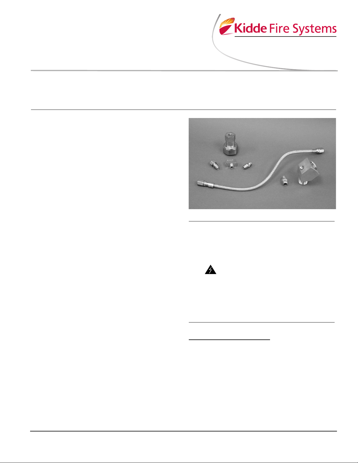
The actuation assembly kit for the 225-lb. and 395-lb.
ADS (P/N 06-129882-001) consists of seven parts (see
Table 1). The nitrogen fitting threads into the orifice fitting.
The 1/8-in. flare allows for the connection of the actuation
hose, which is then fitted into the 1/8-in. branch tee for
operation of the pressure operated control head. A
Schrader valve and cap is then added to the 1/8-in. tee
as a safety for venting off residual pressure after discharge and before decommissioning of the system.
INSTALLATION
Once the nitrogen driver cylinder and the agent storage
cylinder are safely secured and attached to system piping, the actuation assembly can be connected using the
following procedure. Inspect and assemble the kit components separately, prior to attaching to the agent storage cylinder.
A UTC Fire & Security Company
Effective: April 2007
K-90-103
• Pressure Relief Device Included for Safe Disassembly
• UL Listed
• FM Approved
The agent storage cylinder must be
permanently connected into the system piping. Never attach the control
head to the cylinder valve until the cylinders are secured in brackets or racking and the hose is attached to the
agent cylinder. Under no circumstances should the control head
WARNING
remain attached to the cylinder valve
after removal from service or during
shipment, handling, storage or filling.
In the event of inadvertent discharge,
failure to follow these instructions
could result in death, serious bodily
injury and/or property damage.
ASSEMBLY:
Assembly of Kit Components
1. Apply thread tape to male thread of nitrogen transfer
fitting.
2. Apply thread tape to the NPT male thread of the first
1/8-in. x 1/4-in. flared fitting, thread NPT male into
the nitrogen transfer fitting and tighten.
3. Take the two assembled components and thread
into orifice fitting already attached to the nitrogen diffuser assembly, then tighten.
4. Apply thread tape to the male end of 1/8-in. branch
tee and thread into the pressure operated control
head (P/N 878737). Tighten the branch tee.
Page 2
5. Apply thread tape to the NPT male thread of the
second 1/8-in. x 1/4-in. flared fitting and thread into
one side of the 1/8-in. branch tee. Tighten the flared
fitting.
6. Apply thread tape to the male end of the Schrader
valve. Securely threading the male end into the
open end of the 1/8-in. branch tee. Apply Schrader
cap to Schrader fitting.
7. Connect 1/4-in. actuation hose to flare fitting that
was applied to the 1/8-in. branch tee.
8. Connect the other end of the 1/4-in. actuation hose
into the flare fitting that was connected in the busing
in Step 3.
9. Remove the protection cap from the cylinder valve.
10. Using a suitable wrench, assemble control head to
cylinder valve and tighten swivel nut securely.
MAINTENANCE
MONTHLY:
Inspect components for cracks, corrosion, grime, etc.
Ensure that the assembled fittings are tightly secured at
each of their respective connections and to the agent cylinder. If any defects are found during the monthly inspection, immediately contact a Kidde Distributor to service
the systems. Please refer to the Design, Installation,
Operation and Maintenance Manual for more details (P/N
90-FM200M-030).
ORDERING INFORMATION
Table 1: Actuation Assembly Kit Part Numbers
Item
No.
Qty. Part Number Description
1 1 06-236124-001 NitrogenTransfer Fitting
3
4
3
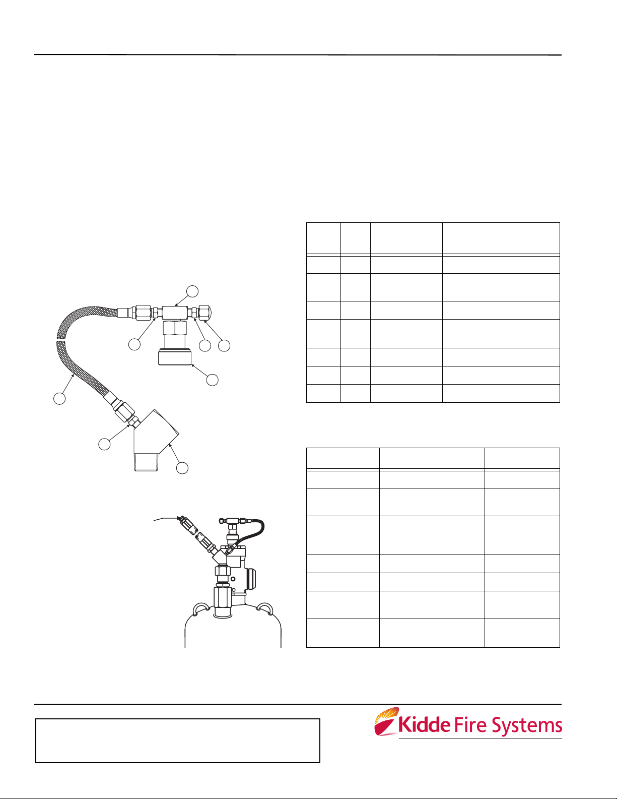
Figure 1. Actuation Kit Assembly
CONNECT TO NITROGEN DRIVER
FOR NITROGEN MANIFOLD SYSTEMS,
USING P/N 06-118207-00X
USE HOSE P/N 06-118324-001*
PIPING MANIFOLD, REFER TO THE DESIGN,
MAINTENANCE MANUAL, P/N 90-FM200M-030.
*NOTE: TO CONNECT INTO
INSTALLATION,OPERATION AND
5
7
6
2
1. FITTING–NITROGEN TRANSFER
2. VALVE–PNEUMATIC ACTUATOR
3. FITTING–FLARED 1/8" x 1/4”
4. HOSE–FLEXIBLE 3/16”
5. TEE–1/8" BRANCH
6. VALVE–SCHRADER
7. CAP–SCHRADER VALVE
1
2 1 878737 Pressure Operated Control
Head
3 2 06-118191-001 Fitting flared 1/8-in. x 1/4-in.
4 1 06-118193-001 3/16-in. Flexible Actuation
Hose, 16-in. length
5 1 06-118192-001 1/8-in. Branch Tee
6 1 WK-263303-000 1/8-in. Schrader Valve
7 1 WK-263304-000 1/8-in. Schrader Valve Cap
SPECIFICATIONS
Table 2: Materials Specifications
Part Number Description Material
06-236124-001 Nitrogen Transfer Fitting Brass
06-118191-001 1/8-in. x 1/4-in.
Flared Fittings
06-118193-001 3/16-in. Flexible
Actuation Hose
06-118192-001 1/8-in. Branch Tee Brass
WK-263303-000 1/8-in. Schrader Valve Brass
Brass
Stainless Steel
Braiding, Brass
Fittings
Figure 2. Cylinder and Valve Assembly
with Assembled Actuation Components
This literature is provided for informational purposes only. KIDDE-FENWAL, INC.
assumes no responsibility for the product’s suitability for a particular application. The
product must be properly applied to work correctly.
If you need more information on this product, or if you have a particular problem or question, contact KIDDE-FENWAL, INC., Ashland, MA 01721. Telephone: (508) 881-2000.
K-90-103 Rev AB © 2007 Kidde-Fenwal Inc. Printed in USA
WK-263304-000 1/8-in. Schrader Valve
Cap
878737 Pressure Operated
Control Head
A UTC Fire & Security Company
400 Main Street
Ashland, MA 01721
Ph: 508.881.2000
Fax: 508.881.8920
www.kiddefiresystems.com
Brass
Brass
 Loading...